以下の例示的な複数の実施形態には、同様の構成要素が含まれている。よって、以下では、同様の構成要素には共通の符号が付されるとともに、重複する説明が部分的に省略される。また、各図では、便宜上、方向(X方向、Y方向、Z方向)が示されている。X方向は、表示画面4aに対する正面視での長手方向、Y方向は、表示画面4aに対する正面視での短手方向、Z方向は表示画面4aに対する正面視での前後方向(奥行方向、筐体3Aの厚さ方向)である。X方向、Y方向、およびZ方向は、相互に直交している。
The following exemplary embodiments include similar components. Therefore, below, the same code | symbol is attached | subjected to the same component, and the overlapping description is partially abbreviate | omitted. Moreover, in each figure, the direction (X direction, Y direction, Z direction) is shown for convenience. The X direction is the longitudinal direction when viewed from the front with respect to the display screen 4a, the Y direction is the lateral direction when viewed from the front with respect to the display screen 4a, and the Z direction is the front and rear direction when viewed from the front with respect to the display screen 4a (depth direction, housing) 3A thickness direction). The X direction, the Y direction, and the Z direction are orthogonal to each other.
また、以下の実施形態では、電子機器がテレビジョン受像機またはパーソナルコンピュータとして構成された場合が例示されるが、本実施形態にかかる電子機器は、これらには限定されない。本実施形態にかかる電子機器は、例えば、スマートフォンや、スマートブック、携帯電話機、PDA(personal digital assistant)、映像表示装置、テレビ電話機等の種々の電子機器として構成することができる。
Moreover, in the following embodiment, the case where an electronic device is comprised as a television receiver or a personal computer is illustrated, However, The electronic device concerning this embodiment is not limited to these. The electronic device according to the present embodiment can be configured as various electronic devices such as a smartphone, a smart book, a mobile phone, a PDA (personal digital assistant), a video display device, and a video phone.
<第1実施形態>
本実施形態では、一例として、図1,2に示されるように、電子機器の一例であるテレビジョン受像機1Aは、支持部2A(支部、台、スタンド)と、筐体3Aと、を備える。具体的に、支持部2Aは、机や、棚、台等の載置部(載置面、図示されず)上に載置され、筐体3Aを起立された状態に支持する。支持部2Aは、筐体3Aを固定的に支持してもよいし、移動可能(回動可能、スライド可能)に支持してもよい。筐体3Aの支持部2Aに対する移動形態(回動形態)としては、例えばチルトや、スイベル、ピボット等がある。
<First Embodiment>
In the present embodiment, as an example, as illustrated in FIGS. 1 and 2, a television receiver 1 </ b> A that is an example of an electronic device includes a support portion 2 </ b> A (a support portion, a stand, a stand) and a housing 3 </ b> A. . Specifically, the support portion 2A is placed on a placement portion (a placement surface, not shown) such as a desk, shelf, or table, and supports the housing 3A in an upright state. The support portion 2A may support the housing 3A in a fixed manner, or may be movably supported (turnable and slidable). Examples of the movement form (rotation form) of the housing 3A with respect to the support portion 2A include tilt, swivel, and pivot.
また、本実施形態では、一例として、図1からわかるように、筐体3Aは、正面視および背面視では矩形状(本実施形態では一例として長方形状)の外観を呈している。また、図2に示されるように、筐体3Aは、前後方向(筐体3Aの厚さ方向、Z方向)に薄い偏平な直方体状に構成されている。筐体3Aは、前面3a(正面、面、面部)とその反対側の後面3b(背面、面、面部)と、を有する。前面3aと後面3bとは略並行して(本実施形態では一例として平行に)設けられている。また、図1に示されるように、筐体3Aは、正面視では、四つの端部3c〜3f(辺部、縁部)と、四つの角部3g〜3jと(尖部、曲部、端部)、を有する。また、端部3c,3eは、長辺部の一例である。端部3d,3fは、短辺部の一例である。
In the present embodiment, as an example, as can be seen from FIG. 1, the housing 3 </ b> A has a rectangular appearance (in the present embodiment, a rectangular shape as an example) in front view and rear view. Further, as shown in FIG. 2, the housing 3 </ b> A is configured in a flat rectangular parallelepiped shape that is thin in the front-rear direction (the thickness direction of the housing 3 </ b> A, the Z direction). The housing 3A has a front surface 3a (front surface, surface, surface portion) and a rear surface 3b (back surface, surface, surface portion) on the opposite side. The front surface 3a and the rear surface 3b are provided substantially in parallel (in the present embodiment, as an example, in parallel). Further, as shown in FIG. 1, the housing 3 </ b> A has four end portions 3 c to 3 f (side portions and edge portions) and four corner portions 3 g to 3 j (points, curved portions, End). The ends 3c and 3e are examples of long sides. The ends 3d and 3f are examples of short sides.
また、筐体3Aは、前面3aを有する壁部3k(部分、プレート、フレーム、前壁部、表壁部、天壁部)と、後面3bを有する壁部3m(部分、プレート、後壁部、裏壁部、底壁部、第二壁部)と、を有する。壁部3k,3mは、矩形状(本実施形態では一例として長方形状)である。また、壁部3kは枠状であり、壁部3mは板状である。また、筐体3Aは、壁部3kと壁部3mとの間に亘った側面3p(面、周面)を有する四つの壁部3n(部分、プレート、側壁部、端壁部、立壁部、亘部、第一壁部)を有する。壁部3kには、矩形状の開口部3rが設けられている。
The housing 3A includes a wall 3k (part, plate, frame, front wall, front wall, top wall, top wall) having a front surface 3a and a wall 3m (part, plate, rear wall) having a rear surface 3b. , Back wall part, bottom wall part, second wall part). The walls 3k and 3m are rectangular (in the present embodiment, rectangular as an example). Moreover, the wall part 3k is frame shape, and the wall part 3m is plate shape. Further, the housing 3A includes four wall portions 3n (parts, plates, side wall portions, end wall portions, standing wall portions, side surfaces 3p (surfaces, peripheral surfaces) extending between the wall portions 3k and 3m. Cross section, first wall section). The wall 3k is provided with a rectangular opening 3r.
さらに、筐体3Aは、複数の部品(分割体、部材)が組み合わせられて構成されている。筐体3Aは、一例としては、少なくとも壁部3kを含む第一部材3Fr(第一部分、前側部材、カバー、ベゼル、フレーム)と、少なくとも壁部3mを含む第二部材3Rr(第二部分、後側部材、ベース、ボトム、プレート)とを有する。また、壁部3nは、本実施形態では、第一部材3Frの一部として構成されている。壁部3nは、筐体3Aの厚さ方向の開口部3rが設けられた側の端部3n1(一端部、前端部、前面3a)とその反対側の端部3n2(他端部、後端部、後面3b)とに亘り、表示装置4の周縁部(側面4b、図3,4参照)を覆っている。
Further, the housing 3A is configured by combining a plurality of parts (divided bodies, members). As an example, the housing 3A includes a first member 3Fr (first portion, front member, cover, bezel, frame) including at least a wall 3k and a second member 3Rr (second portion, rear) including at least a wall 3m. Side member, base, bottom, plate). Further, the wall 3n is configured as a part of the first member 3Fr in the present embodiment. The wall 3n includes an end 3n1 (one end, front end, front surface 3a) on the side where the opening 3r in the thickness direction of the housing 3A is provided and an end 3n2 (other end, rear end) on the opposite side. And the rear surface 3b), the peripheral portion of the display device 4 (see the side surface 4b, see FIGS. 3 and 4) is covered.
また、本実施形態では、一例として、第一部材3Frは、合成樹脂材料で構成され、第二部材3Rrは、金属材料で構成される。上述したように、第一部材3Frは、壁部3nを含む。よって、この第一部材3Frが合成樹脂材料より比重が大きい金属材料で構成されると、筐体3Aが重くなりやすい。また、第二部材3Rrは、壁部3nを含まない。よって、この第二部材3Rrが金属材料より柔らかい(曲がりやすい、撓みやすい)合成樹脂材料で構成されると、筐体3Aの剛性が低くなりやすい。この点、本実施形態では、一例として、第一部材3Frは合成樹脂材料で構成され、第二部材3Rrは金属材料で構成されるため、筐体3Aの軽量化と剛性および強度の向上とが両立されやすい。なお、このような材料(材質)の組み合わせはあくまで一例であって、他の材料の組み合わせでも構わない。
In the present embodiment, as an example, the first member 3Fr is made of a synthetic resin material, and the second member 3Rr is made of a metal material. As described above, the first member 3Fr includes the wall 3n. Therefore, if the first member 3Fr is made of a metal material having a specific gravity greater than that of the synthetic resin material, the housing 3A tends to be heavy. The second member 3Rr does not include the wall 3n. Therefore, when the second member 3Rr is made of a synthetic resin material that is softer (easily bent or easily bent) than the metal material, the rigidity of the housing 3A is likely to be lowered. In this regard, in the present embodiment, as an example, the first member 3Fr is made of a synthetic resin material, and the second member 3Rr is made of a metal material. Therefore, the weight reduction of the housing 3A and the improvement in rigidity and strength are achieved. It is easy to be compatible. Note that such a combination of materials (materials) is merely an example, and a combination of other materials may be used.
また、本実施形態では、一例として、図3,4に示されるように、筐体3A内には、表示装置4(表示部、ディスプレイ、パネル、表示部品)が収容されている。具体的には、表示装置4の、前面3a側に位置した表示画面4aは、開口部3rを介して筐体3Aの前方(外方)に露出している。使用者は、前方側から開口部3rを介して表示画面4aを視認することができる。表示装置4は、正面視では矩形状(本実施形態では一例として長方形状)の外観を呈している。また、表示装置4は、前後方向に薄い偏平な直方体状に構成されている。表示装置4は、例えば、液晶ディスプレイ(LCD,liquid crystal display)や、有機ELディスプレイ(OELD,organic electro-luminescent display)、プラズマディスプレイ(PDP,plasma display panel)等である。
In the present embodiment, as an example, as shown in FIGS. 3 and 4, a display device 4 (display unit, display, panel, display component) is accommodated in the housing 3 </ b> A. Specifically, the display screen 4a located on the front surface 3a side of the display device 4 is exposed to the front (outward) of the housing 3A through the opening 3r. The user can visually recognize the display screen 4a from the front side through the opening 3r. The display device 4 has a rectangular appearance in a front view (in this embodiment, a rectangular shape as an example). Further, the display device 4 is configured in a flat rectangular parallelepiped shape that is thin in the front-rear direction. The display device 4 is, for example, a liquid crystal display (LCD), an organic EL display (OELD), a plasma display (PDP), or the like.
また、本実施形態では、一例として、図3,4に示されるように、表示装置4の前側(表側、壁部3k側)には、透明な比較的薄い矩形状の入力操作パネル5(一例としてはタッチパネル、タッチセンサ、操作面)が設けられている。入力操作パネル5は、表示画面4aを覆っている。操作者(ユーザ等)は、例えば手指やスタイラス等によって、入力操作パネル5に対して、触れる、押す、擦る、あるいは入力操作パネル5の近傍で動かす等の操作を行うことで、入力処理を実行することができる。また、表示装置4の表示画面4aから出た光は、入力操作パネル5を通過して壁部3kの開口部3rから筐体3Aの前方(外方)へ出る。入力操作パネル5は、入力部の一例である。
In the present embodiment, as an example, as shown in FIGS. 3 and 4, a transparent relatively thin rectangular input operation panel 5 (an example) is provided on the front side (front side, wall 3 k side) of the display device 4. A touch panel, a touch sensor, and an operation surface). The input operation panel 5 covers the display screen 4a. An operator (such as a user) executes input processing by performing operations such as touching, pushing, rubbing, or moving near the input operation panel 5 with the finger or stylus, for example. can do. The light emitted from the display screen 4a of the display device 4 passes through the input operation panel 5 and exits from the opening 3r of the wall 3k to the front (outward) of the housing 3A. The input operation panel 5 is an example of an input unit.
また、本実施形態では、一例として、図3,4に示されるように、表示装置4および入力操作パネル5は、第一部材3Frに支持される。具体的には、表示装置4および入力操作パネル5は、第一部材3Frに、例えば、固定具(固定部品、金具、例えば、ねじ、金具、部品等、図示されず)や接着部(例えば接着剤や両面テープ等、図示されず)を介して固定される。表示装置4および入力操作パネル5は、壁部3kあるいは壁部3n(の端部3n1)に固定される。また、本実施形態では、一例として、第一部材3Fr(の壁部3n)の前側の端部32a(面、端面)が入力操作パネル5の面5a(前面、表面)に沿った方向に並び、当該面5aと連なっている。また、本実施形態では、一例として、壁部3kの前面3aと表示装置4の表示画面4aとが連なっており、それら前面3aおよび表示画面4aを入力操作パネル5が覆っている。
In the present embodiment, as an example, as shown in FIGS. 3 and 4, the display device 4 and the input operation panel 5 are supported by the first member 3Fr. Specifically, the display device 4 and the input operation panel 5 are attached to the first member 3Fr, for example, by a fixture (fixed parts, metal fittings, for example, screws, metal fittings, parts, etc., not shown) or an adhesion part (for example, adhesion). It is fixed via an agent or a double-sided tape (not shown). The display device 4 and the input operation panel 5 are fixed to the wall 3k or the wall 3n (the end 3n1 thereof). In the present embodiment, as an example, the front end portion 32a (surface, end surface) of the first member 3Fr (wall portion 3n) is aligned in a direction along the surface 5a (front surface, surface) of the input operation panel 5. The surface 5a is continuous. In the present embodiment, as an example, the front surface 3a of the wall 3k and the display screen 4a of the display device 4 are connected, and the input operation panel 5 covers the front surface 3a and the display screen 4a.
また、本実施形態では、一例として、図3,4に示されるように、筐体3A内には、表示装置4の後側(裏側、背後側、壁部3m側、表示画面4aとは反対側)に、電気部品としてのバッテリ6(セル、組電池)や基板7,8(回路基板、プリント基板、制御基板、ただし、図3,4には基板8は図示されず)等が収容されている。バッテリ6や、基板7,8、表示装置4等の電気部品は、図示されない配線(ケーブル、フレキシブルケーブル、フレキシブルプリント配線板等)を介して、それぞれ他の電気部品と電気的に接続されている。
In this embodiment, as an example, as shown in FIGS. 3 and 4, the housing 3 </ b> A has a rear side of the display device 4 (back side, back side, wall 3 m side, opposite to the display screen 4 a). The battery 6 (cell, assembled battery) and the boards 7 and 8 (circuit board, printed board, control board, but the board 8 is not shown in FIGS. 3 and 4) etc. ing. The electric components such as the battery 6, the substrates 7 and 8, and the display device 4 are electrically connected to other electric components via wiring (cable, flexible cable, flexible printed wiring board, etc.) not shown. .
本実施形態では、一例として、バッテリ6は、リチウムイオン二次電池として構成されることができる。リチウムイオン二次電池は、非水電解質二次電池の一種であり、電解質中のリチウムイオンが電気伝導を担う。正極材料としては、例えば、マンガンや、ニッケル、リン酸鉄等が用いられ、負極材料としては、例えば、チタン酸リチウム(LTO)等の酸化物系材料や、炭素系材料等が用いられる。また、電解質(一例としては電解液)としては、例えば、フッ素系錯塩(LiBF4)等のリチウム塩が配合された炭酸エチレンや炭酸ジエチル等の有機溶媒等が用いられる。本実施形態では、一例として、バッテリ6は、基板7,8や、表示装置4、スピーカ(図示されず)等の筐体3A内の電気部品や、基板7,8等に、コネクタや配線(いずれも図示されず)等を介して、テレビジョン受像機1Aが映像を表示したり音声を出力したりといった動作を行うために必要な電源電力を供給することができる。また、バッテリ6は、コネクタや配線等(図示されず)を介して基板7,8等に接続された外部装置等に電力を供給することもできる。
In the present embodiment, as an example, the battery 6 can be configured as a lithium ion secondary battery. A lithium ion secondary battery is a kind of non-aqueous electrolyte secondary battery, and lithium ions in the electrolyte are responsible for electrical conduction. Examples of the positive electrode material include manganese, nickel, and iron phosphate. Examples of the negative electrode material include oxide-based materials such as lithium titanate (LTO), carbon-based materials, and the like. Moreover, as an electrolyte (an electrolyte solution as an example), for example, an organic solvent such as ethylene carbonate or diethyl carbonate mixed with a lithium salt such as a fluorine-based complex salt (LiBF4) is used. In the present embodiment, as an example, the battery 6 is connected to the connectors 7 and 8, the electrical components in the housing 3 </ b> A such as the display device 4 and the speaker (not shown), the connectors 7 and 8, etc. The power supply power necessary for the television receiver 1A to perform operations such as displaying video and outputting sound can be supplied via the above. The battery 6 can also supply power to an external device or the like connected to the boards 7 and 8 and the like via a connector, wiring or the like (not shown).
また、本実施形態では、一例として、図1に示されるように、バッテリ6は複数のセル61,62,63を有している。複数のセル61,62,63は、電気的には直列または並列に接続される。また、複数のセル61,62,63は、端部3cに沿って並べられている。また、本実施形態では、一例として、バッテリ6は、回路基板64を有し、複数のセル61,62,63は、各セル61,62,63の電極(図示されず)を介して回路基板64(の導体パターン)に接続(接合)され、一体化されている。このように、複数のセル61,62,63が一体化されることで、セル61,62,63をそれぞれ組み付ける場合に比べて、製造の手間およびコストが低減されやすい。また、回路基板64は、一例としては、基板7,8と各セル61,62,63との間、あるいは、各セル61,62,63間を電気的に接続するバスバー(導体、図示されず)を有する。また、回路基板64には、電気部品(図示されず)が設けられて(実装されて)いる。電気部品と回路基板64の導体パターン(配線パターン、図示されず)とによって、一例としては、各セル61,62,63あるいはバッテリ6の出力電力(電圧)や温度等を監視する機能を実現するための電気回路(電子回路)が構成されている。
In the present embodiment, as an example, as illustrated in FIG. 1, the battery 6 includes a plurality of cells 61, 62, and 63. The plurality of cells 61, 62, and 63 are electrically connected in series or in parallel. The plurality of cells 61, 62, 63 are arranged along the end 3c. In the present embodiment, as an example, the battery 6 includes a circuit board 64, and the plurality of cells 61, 62, 63 are connected to the circuit board via electrodes (not shown) of the cells 61, 62, 63. 64 (the conductor pattern) is connected (joined) and integrated. Thus, by integrating the plurality of cells 61, 62, 63, it is easy to reduce the labor and cost of manufacturing compared to the case where the cells 61, 62, 63 are assembled. The circuit board 64 is, for example, a bus bar (conductor, not shown) that electrically connects the substrates 7 and 8 and the cells 61, 62, and 63 or between the cells 61, 62, and 63. ). The circuit board 64 is provided (mounted) with electrical components (not shown). As an example, the function of monitoring the output power (voltage), temperature, etc. of each cell 61, 62, 63 or battery 6 is realized by the electrical component and the conductor pattern (wiring pattern, not shown) of the circuit board 64. An electric circuit (electronic circuit) is configured.
セル61,62,63は、それぞれ、電解質(電解液)や、電極、セパレータ等が収容(封入)された室(収容部)が設けられた、独立した単電池として構成されている。また、これらセル61,62,63は、いずれも、筐体3Aの厚さ方向(Z方向)に薄く偏平な直方体状(板状、角板状、カード状)に構成されている。また、本実施形態では、一例として、セル61,62,63の最外層は、絶縁性かつ可撓性を有したシート状の外皮(皮、膜)であり、硬質なケース(シェル)は設けられていない。よって、本実施形態によれば、一例としては、ケースを有しない分、バッテリ6(セル61,62,63)がより小型に(薄く)かつより軽量に構成されやすくなり、ひいては、筐体3A(テレビジョン受像機1A)がより小型に(薄く)かつより軽量に構成されやすい。また、本実施形態では、一例として、複数のセル61,62,63が、それぞれ区分されたバッグ(部分)として構成されている。よって、一例としては、複数のセル61,62,63が堅く一体的に結合された場合に比べて、外力の作用等によってバッテリ6に生じる局所的な応力が、より低減されやすい。
Each of the cells 61, 62, and 63 is configured as an independent unit cell provided with a chamber (accommodating portion) in which an electrolyte (electrolytic solution), electrodes, separators, and the like are accommodated (enclosed). Each of the cells 61, 62, and 63 is configured in a rectangular parallelepiped shape (plate shape, square plate shape, card shape) that is thin and flat in the thickness direction (Z direction) of the housing 3A. In this embodiment, as an example, the outermost layer of the cells 61, 62, 63 is an insulating and flexible sheet-like outer skin (skin, film), and a hard case (shell) is provided. It is not done. Therefore, according to the present embodiment, as an example, the battery 6 (cells 61, 62, 63) is easily configured to be smaller (thin) and lighter because there is no case, and as a result, the housing 3A. The (television receiver 1A) is easily configured to be smaller (thin) and lighter. In the present embodiment, as an example, the plurality of cells 61, 62, and 63 are each configured as a partitioned bag (part). Therefore, as an example, local stress generated in the battery 6 due to the action of an external force or the like is more likely to be reduced as compared with a case where the plurality of cells 61, 62, and 63 are firmly and integrally coupled.
また、本実施形態では、一例として、基板7,8の少なくともいずれか一方には、CPU(central processing unit)等の複数の部品9(部品、素子、電子部品、電気部品)が実装されている。部品9には、発熱体が含まれる。発熱量の大きい部品9(発熱体)には、冷却機構(放熱部、受熱部、図示されず)を設けることができる。基板7,8や部品9等によって、制御回路(図示されず)の少なくとも一部が構成されている。制御回路は、例えば、映像信号処理回路や、チューナ部、HDMI(high-definition multimedia interface)信号処理部、AV(audio video)入力端子、リモコン信号受信部、制御部、セレクタ、オンスクリーンディスプレイインタフェース、記憶部(例えば、ROM(read only memory)、RAM(random access memory)、HDD(hard disk drive)等)、音声信号処理回路等を、含むことができる。制御回路は、表示装置4の表示画面4aでの映像(動画や静止画等)の出力や、スピーカ(図示されず)での音声の出力、LED(light emitting diode、図示されず)での発光等を制御する。表示装置4や、スピーカ、LED等は、出力部の一例である。
In the present embodiment, as an example, a plurality of components 9 (components, elements, electronic components, electrical components) such as a CPU (central processing unit) are mounted on at least one of the substrates 7 and 8. . The component 9 includes a heating element. A cooling mechanism (a heat radiating part, a heat receiving part, not shown) can be provided in the component 9 (heat generating element) having a large calorific value. At least a part of a control circuit (not shown) is configured by the substrates 7 and 8 and the components 9 and the like. The control circuit includes, for example, a video signal processing circuit, a tuner unit, an HDMI (high-definition multimedia interface) signal processing unit, an AV (audio video) input terminal, a remote control signal receiving unit, a control unit, a selector, an on-screen display interface, A storage unit (for example, ROM (read only memory), RAM (random access memory), HDD (hard disk drive), etc.), an audio signal processing circuit, and the like can be included. The control circuit outputs video (moving images, still images, etc.) on the display screen 4a of the display device 4, outputs audio from a speaker (not shown), and emits light from an LED (light emitting diode, not shown). Control etc. The display device 4, the speaker, the LED, and the like are examples of the output unit.
また、本実施形態では、一例として、図1,3,4に示されるように、バッテリ6ならびに基板7,8(ただし、図3,4には基板8は図示されず)は、筐体3Aの厚さ方向(Z方向)には重ならず、壁部3mの筐体内側の面3s(第一面)に沿って位置されている。よって、バッテリ6と基板7,8とが厚さ方向に重なった場合に比べて、筐体3Aをより薄く構成することができる。また、バッテリ6の面6a(第二面)、基板7の面7a(第二面)ならびに基板8の面(図示されず、面3s側の面、第二面)と壁部3mの面3sとは、接着剤あるいは両面テープ(粘着テープ)等を介して少なくとも部分的に接着(密着)されている。よって、一例としては、バッテリ6や基板7,8を筐体3Aに固定する固定具(例えばねじ)等の部品を減らしやすく、筐体3Aひいてはテレビジョン受像機1Aがより軽量に構成されやすくなる。また、一例としては、バッテリ6あるいは基板7,8の組立の手間が減りやすくなる。また、一例としては、壁部3mの面3sとバッテリ6の面6aあるいは基板7,8の面7aとが接着された分、壁部3mが曲がったりねじれたりしにくくなる。すなわち、一例としては、壁部3mを、バッテリ6や基板7,8によって補強することができる。また、一例としては、バッテリ6や基板7,8で生じた熱が、壁部3mを介して筐体3Aの外へ放出されやすい。
In the present embodiment, as an example, as shown in FIGS. 1, 3, and 4, the battery 6 and the boards 7 and 8 (however, the board 8 is not shown in FIGS. 3 and 4) are included in the housing 3 </ b> A. It is positioned along the inner surface 3s (first surface) of the wall 3m without overlapping in the thickness direction (Z direction). Therefore, the housing 3A can be configured to be thinner than when the battery 6 and the boards 7 and 8 overlap in the thickness direction. Also, the surface 6a (second surface) of the battery 6, the surface 7a (second surface) of the substrate 7, the surface of the substrate 8 (not shown, the surface on the surface 3s side, the second surface) and the surface 3s of the wall 3m. Is at least partially adhered (adhered) via an adhesive or a double-sided tape (adhesive tape). Therefore, as an example, it is easy to reduce parts such as a fixture (for example, a screw) for fixing the battery 6 and the boards 7 and 8 to the housing 3A, and the housing 3A and thus the television receiver 1A can be easily configured to be lighter. . Further, as an example, the labor for assembling the battery 6 or the boards 7 and 8 can be easily reduced. As an example, the wall 3m is less likely to bend or twist as much as the surface 3s of the wall 3m is bonded to the surface 6a of the battery 6 or the surface 7a of the substrates 7 and 8. That is, as an example, the wall 3 m can be reinforced by the battery 6 and the boards 7 and 8. As an example, heat generated in the battery 6 and the boards 7 and 8 is easily released outside the housing 3A through the wall 3m.
また、本実施形態では、一例として、バッテリ6の面6aあるいは基板7,8の面7aと壁部3mの面3sとが、壁部3mの中心(中心線CL、図1参照)を挟んだ両側に亘って、好適には面6a,7aの比較的広い領域同士が、さらに好適には、面6a,7aの端部3c側の端部6a1,7a1と端部3e側の端部6a2,7a2とに亘って、接着されている。よって、一例としては、壁部3mの局所的な曲げが抑制されやすい。さらに、本実施形態では、一例として、バッテリ6が端部3c(第二端部)に寄せて位置され、基板7,8が端部3e(第一端部)に寄せて位置されている。よって、一例としては、壁部3mが端部3c側から端部3e側に亘るより広い範囲で補強されやすい。また、一例としては、バッテリ6と端部3eとの間の領域S1または基板7,8と端部3cとの間の領域S2が、他の回路基板や配線等を位置させるのに利用されやすくなる。さらに、本実施形態では、一例として、バッテリ6あるいは基板7は、端部3cまたは端部3eとの間に隙間をあけて位置されている。よって、本実施形態によれば、一例としては、より手指等が当たりやすい端部3c,3eがバッテリ6あるいは基板7,8で生じた熱によって、暖められるのが抑制されやすい。
In this embodiment, as an example, the surface 6a of the battery 6 or the surfaces 7a of the substrates 7 and 8 and the surface 3s of the wall 3m sandwich the center of the wall 3m (center line CL, see FIG. 1). Over both sides, preferably relatively wide areas of the surfaces 6a and 7a are more preferably the end portions 6a1 and 7a1 on the end portion 3c side of the surfaces 6a and 7a and the end portion 6a2 on the end portion 3e side. 7a2 is bonded. Therefore, as an example, local bending of the wall 3m is likely to be suppressed. Furthermore, in this embodiment, as an example, the battery 6 is positioned close to the end 3c (second end), and the substrates 7 and 8 are positioned close to the end 3e (first end). Therefore, as an example, the wall 3m is easily reinforced in a wider range from the end 3c side to the end 3e side. As an example, the region S1 between the battery 6 and the end 3e or the region S2 between the substrates 7 and 8 and the end 3c can be easily used for positioning other circuit boards, wirings, and the like. Become. Furthermore, in this embodiment, as an example, the battery 6 or the substrate 7 is positioned with a gap between the end 3c or the end 3e. Therefore, according to the present embodiment, as an example, it is easy to suppress the end portions 3c and 3e that are easier to touch with fingers and the like from being heated by the heat generated in the battery 6 or the boards 7 and 8.
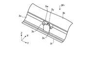
また、本実施形態では、一例として、図5に示されるように、第二部材3Rrは、壁部3mから第一部材3Frの壁部3nの筐体内側で壁部3nに沿って突出した突出部3t(第四突出部)を有している。突出部3tに設けられた係部31a(第一係部)と壁部3nに設けられた係部31b(第二係部)とが筐体3Aの厚さ方向(Z方向)に係わっている。本実施形態では、一例として、係部31aは貫通孔として構成され、係部31bは爪部(突出部、突起)として構成されている。これら係部31aと係部31bとの係わりによって、第一部材3Frと第二部材3Rrとが結合されている。このように、本実施形態では、一例として、比較的簡素な構成によって、第一部材3Frと第二部材3Rrとが結合されている。
Further, in the present embodiment, as an example, as shown in FIG. 5, the second member 3Rr protrudes along the wall 3n from the wall 3m to the inside of the housing of the wall 3n of the first member 3Fr. It has a portion 3t (fourth projecting portion). The engaging portion 31a (first engaging portion) provided on the protruding portion 3t and the engaging portion 31b (second engaging portion) provided on the wall 3n are engaged in the thickness direction (Z direction) of the housing 3A. . In the present embodiment, as an example, the engaging portion 31a is configured as a through hole, and the engaging portion 31b is configured as a claw portion (protruding portion, protrusion). The first member 3Fr and the second member 3Rr are coupled by the engagement between the engagement portion 31a and the engagement portion 31b. Thus, in the present embodiment, as an example, the first member 3Fr and the second member 3Rr are coupled with a relatively simple configuration.
また、本実施形態では、一例として、図7に示されるように、第二部材3Rrは、突出部3u(第一突出部)を有している。突出部3uは、組み立てられた状態での第一部材3Frの壁部3n(図6参照)の筐体内側で壁部3mから壁部3nに沿って突出する。突出部3uの筐体内側には、リブ3v(突出部)が設けられている。また、図6に示されるように、第一部材3Frは、突出部3w(第二突出部、壁部)を有している。突出部3wは、組み立てられた状態で突出部3u(図7参照)を壁部3nとの間に挟んだ状態で、壁部3kから壁部3mに向けて(Z方向に沿って)突出している。すなわち、突出部3wは、壁部3nとの間に突出部3uを受け容れ可能な隙間(一例としては突出部3uの厚さより僅かに広い隙間)をもって突出している。さらに、第一部材3Frは、二つの突出部3x(第三突出部、壁部)を有している。二つの突出部3xは、突出部3uと壁部3k,3mの周縁に沿った方向(表示装置4の周縁に沿った方向、図6,7ではY方向)に係わって壁部3kから壁部3mに向けて突出している。すなわち、二つの突出部3xは、それらの間に突出部3uを受け容れ可能な隙間(一例としては突出部3uの幅より僅かに広い隙間)をもって突出している。本実施形態では、一例として、第一部材3Frと第二部材3Rrとが組み立てられた状態では、突出部3uは、壁部3nと突出部3wとの間にX方向に挟まれるとともに、二つの突出部3xにY方向に挟まれる。図6に示されるように、突出部3w,3x(壁部)は、互いにC字状に接続され、さらに壁部3nに接続されている。すなわち、壁部3nおよび突出部3w,3xによって、筒状(角筒状、環状)の収容部が設けられている。このような構成により、本実施形態では、一例として、第二部材3Rrに設けられた突出部3uが第一部材3Frに対して、壁部3nの厚さ方向(図6,7の例ではY方向)や壁部3mに沿った長手方向(図6,7の例ではX方向)に移動するのが抑制される。よって、本実施形態によれば、一例としては外力等によって第一部材3Frと第二部材3Rrとが互いに接触する縁部で離間するのが、比較的簡素な構成によって抑制されやすい。なお、突出部3wには、組み立てられた状態で、リブ3vを受け容れる切欠部3y(凹部)が設けられている。よって、突出部3wのうち切欠部3yの縁部も、突出部3xと同様に、第三突出部として機能する。
In the present embodiment, as an example, as shown in FIG. 7, the second member 3 </ b> Rr has a protruding portion 3 u (first protruding portion). The protrusion 3u protrudes along the wall 3n from the wall 3m inside the housing of the wall 3n (see FIG. 6) of the first member 3Fr in the assembled state. A rib 3v (protrusion) is provided inside the housing of the protrusion 3u. Moreover, as FIG. 6 shows, 1st member 3Fr has the protrusion part 3w (2nd protrusion part, wall part). The protrusion 3w protrudes from the wall 3k toward the wall 3m (along the Z direction) with the protrusion 3u (see FIG. 7) sandwiched between the wall 3n and the assembled part 3w. Yes. That is, the protruding portion 3w protrudes with a gap (for example, a gap slightly wider than the thickness of the protruding portion 3u) that can receive the protruding portion 3u between the wall portion 3n. Further, the first member 3Fr has two protruding portions 3x (third protruding portion, wall portion). The two protrusions 3x are related to the protrusion 3u and the direction along the periphery of the walls 3k, 3m (the direction along the periphery of the display device 4, the Y direction in FIGS. 6 and 7). It protrudes toward 3m. That is, the two protrusions 3x protrude with a gap (for example, a gap slightly wider than the width of the protrusion 3u) that can receive the protrusion 3u between them. In the present embodiment, as an example, in a state where the first member 3Fr and the second member 3Rr are assembled, the protrusion 3u is sandwiched in the X direction between the wall 3n and the protrusion 3w, and two The protrusion 3x is sandwiched in the Y direction. As shown in FIG. 6, the projecting portions 3w and 3x (wall portions) are connected to each other in a C shape and further connected to the wall portion 3n. That is, a cylindrical (square cylindrical, annular) accommodating portion is provided by the wall portion 3n and the protruding portions 3w and 3x. With such a configuration, in the present embodiment, as an example, the protrusion 3u provided on the second member 3Rr is in the thickness direction of the wall 3n with respect to the first member 3Fr (Y in the example of FIGS. 6 and 7). Direction) and a longitudinal direction along the wall 3m (X direction in the examples of FIGS. 6 and 7) are suppressed. Therefore, according to the present embodiment, as an example, the first member 3Fr and the second member 3Rr are easily separated from each other at the edge where they are in contact with each other by an external force or the like with a relatively simple configuration. The protruding portion 3w is provided with a notch 3y (recessed portion) that receives the rib 3v in an assembled state. Therefore, the edge part of the notch part 3y also functions as a 3rd protrusion part similarly to the protrusion part 3x among the protrusion parts 3w.
以上、説明したように、本実施形態では、一例として、第一部材3Frが壁部3kと壁部3nとを有し、第二部材3Rrが壁部3mを有した。よって、本実施形態によれば、一例としては、壁部3kと壁部3nとを一体的に有した第一部材3Frによって、筐体3Aの剛性および強度の高い構成が得られやすい。また、壁部3mの面3sの所要の範囲に、バッテリ6や基板7,8等の電気部品の面6a,7aを接着することで、壁部3mが補強されやすい。
As described above, in the present embodiment, as an example, the first member 3Fr has the wall 3k and the wall 3n, and the second member 3Rr has the wall 3m. Therefore, according to the present embodiment, as an example, the first member 3Fr integrally including the wall 3k and the wall 3n can easily obtain a configuration with high rigidity and strength of the housing 3A. Moreover, the wall 3m can be easily reinforced by bonding the surfaces 6a and 7a of the electrical components such as the battery 6 and the boards 7 and 8 to the required range of the surface 3s of the wall 3m.
また、本実施形態では、一例として、第二部材3Rrは、壁部3mから壁部3nの筐体内側で当該壁部3nに沿って突出した突出部3uを有し、第一部材3Frは、突出部3uを壁部3nとの間に挟んだ状態で壁部3mに向けて突出した突出部3wを有した。よって、本実施形態によれば、一例としては、突出部3uが壁部3mと突出部3wとの間に挟まれた構成により、壁部3nの厚さ方向に作用した外力によって、第一部材3Frと第二部材3Rrとが離間するのが抑制されやすい。
In the present embodiment, as an example, the second member 3Rr has a protruding portion 3u that protrudes along the wall 3n from the wall 3m to the inside of the housing of the wall 3n, and the first member 3Fr is The protrusion 3w protruded toward the wall 3m with the protrusion 3u sandwiched between the wall 3n. Therefore, according to the present embodiment, as an example, the first member is caused by an external force acting in the thickness direction of the wall 3n due to the configuration in which the protrusion 3u is sandwiched between the wall 3m and the protrusion 3w. It is easy to suppress separation of 3Fr and the second member 3Rr.
また、本実施形態では、一例として、第一部材3Frは、突出部3wと表示装置4の周縁に沿った方向に係わり壁部3mに向けて突出した突出部3xを有した。よって、本実施形態によれば、一例としては、突出部3uが突出部3xと係わった構成により、表示装置4の周縁に沿った方向に作用した外力によって、第一部材3Frと第二部材3Rrとが離間するのが抑制されやすい。
In the present embodiment, as an example, the first member 3Fr has a protruding portion 3x that protrudes toward the wall portion 3m in a direction along the protruding portion 3w and the peripheral edge of the display device 4. Therefore, according to the present embodiment, as an example, the first member 3Fr and the second member 3Rr are configured by the external force acting in the direction along the periphery of the display device 4 due to the configuration in which the protrusion 3u is engaged with the protrusion 3x. It is easy to be suppressed from separating.
また、本実施形態では、一例として、第二部材3Rrは、壁部3mから壁部3kの筐体内側に沿って突出し係部31aが設けられた突出部3tを有し、第一部材3Frは、壁部3nに設けられ係部31aと係わる係部31bを有した。よって、本実施形態によれば、一例としては、比較的簡素な構成によって、第一部材3Frと第二部材3Rrとを結合することができる。また、一例としては、外部から見えない結合部を得ることができる。
In the present embodiment, as an example, the second member 3Rr has a protruding portion 3t that protrudes from the wall portion 3m along the inside of the housing of the wall portion 3k and is provided with an engaging portion 31a, and the first member 3Fr is The engaging portion 31b is provided on the wall 3n and is associated with the engaging portion 31a. Therefore, according to this embodiment, as an example, the first member 3Fr and the second member 3Rr can be coupled with a relatively simple configuration. As an example, it is possible to obtain a coupling portion that is not visible from the outside.
<第2実施形態>
本実施形態にかかる電子機器1Bは、例えば、所謂スレート型、タブレット型、ソフトキーボードの機能を有した表示装置等の、パーソナルコンピュータ、テレビジョン受像機、スマートフォン、スマートブック、携帯電話機、PDA等である。
Second Embodiment
The electronic apparatus 1B according to the present embodiment is, for example, a personal computer, a television receiver, a smartphone, a smart book, a mobile phone, a PDA, or the like such as a display device having a so-called slate type, tablet type, or soft keyboard function. is there.
本実施形態では、一例として、図8,9からわかるように、電子機器1Bの筐体3Bは、正面視および背面視では矩形状(本実施形態では一例として長方形状)の外観を呈している。また、筐体3Bは、前後方向(筐体3Bの厚さ方向、Z方向)に薄い偏平な直方体状に構成されている。筐体3Bは、前面3a(正面、面、面部)とその反対側の後面3b(背面、面、面部)と、を有する。前面3aと後面3bとは略並行して(本実施形態では一例として平行に)設けられている。また、筐体3Bは、正面視では、四つの端部3c〜3f(辺部、縁部)と、四つの角部3g〜3j(尖部、曲部、端部)と、を有する。端部3c,3eは、長辺部の一例である。端部3d,3fは、短辺部の一例である。
In this embodiment, as an example, as can be seen from FIGS. 8 and 9, the housing 3 </ b> B of the electronic device 1 </ b> B has a rectangular appearance (in the present embodiment, a rectangular shape as an example) when viewed from the front and back. . The housing 3B is configured in a flat rectangular shape that is thin in the front-rear direction (thickness direction of the housing 3B, Z direction). The housing 3B has a front surface 3a (front surface, surface, surface portion) and a rear surface 3b (back surface, surface, surface portion) on the opposite side. The front surface 3a and the rear surface 3b are provided substantially in parallel (in the present embodiment, as an example, in parallel). Further, the housing 3B has four end portions 3c to 3f (side portions and edge portions) and four corner portions 3g to 3j (pointed portions, curved portions, and end portions) in a front view. The end portions 3c and 3e are examples of long side portions. The ends 3d and 3f are examples of short sides.
また、筐体3Bは、前面3aを有する壁部3k(部分、プレート、フレーム、前壁部、表壁部、天壁部)と、後面3bを有する壁部3m(部分、プレート、後壁部、裏壁部、底壁部、第二壁部)と、を有する。壁部3k,3mは、矩形状(本実施形態では一例として長方形状)である。また、筐体3Bは、壁部3kと壁部3mとの間に亘った側面3p(面、周面)を有する四つの壁部3n(部分、プレート、側壁部、端壁部、立壁部、亘部、第一壁部)を有する。そして、壁部3kには、一例としては矩形状の開口部3rが設けられている。
The housing 3B includes a wall 3k (part, plate, frame, front wall, front wall, top wall, top wall) having a front surface 3a and a wall 3m (part, plate, rear wall) having a rear surface 3b. , Back wall part, bottom wall part, second wall part). The walls 3k and 3m are rectangular (in the present embodiment, rectangular as an example). Further, the housing 3B has four wall portions 3n (parts, plates, side wall portions, end wall portions, standing wall portions, having side surfaces 3p (surfaces, peripheral surfaces) extending between the wall portions 3k and 3m. Cross section, first wall section). The wall 3k is provided with a rectangular opening 3r as an example.
さらに、筐体3Bは、複数の部品(分割体)が組み合わせられて構成されることができる。筐体3Bは、一例としては、少なくとも壁部3kを含む第一部材3Fr(第一部分、前側部材、カバー、ベゼル、フレーム)と、少なくとも壁部3mを含む第二部材3Rr(第二部分、後側部材、ベース、ボトム、プレート)とを有する。また、壁部3nは、本実施形態では、基本的には第一部材3Frの一部として構成されている。すなわち、壁部3nは、筐体3Bの厚さ方向の開口部3rが設けられた側の端部3n1(一端部、前端部、前面3a)とその反対側の端部3n2(他端部、後端部、後面3b)とに亘り(図8,17等参照)、表示装置4の周縁部(側面4b、図10参照)を覆っている。また、壁部3nは、他の壁部3k,3bより厚い。よって、筐体3Bの厚さ方向の剛性および強度がより高まりやすい。
Furthermore, the housing 3B can be configured by combining a plurality of components (divided bodies). For example, the housing 3B includes a first member 3Fr (first portion, front member, cover, bezel, frame) including at least a wall portion 3k and a second member 3Rr (second portion, rear portion) including at least a wall portion 3m. Side member, base, bottom, plate). In the present embodiment, the wall 3n is basically configured as a part of the first member 3Fr. That is, the wall 3n includes an end 3n1 (one end, front end, front surface 3a) on the side where the opening 3r in the thickness direction of the housing 3B is provided and an end 3n2 (other end, The peripheral edge (see the side surface 4b, see FIG. 10) of the display device 4 is covered over the rear end portion and the rear surface 3b) (see FIGS. 8, 17 etc.). The wall 3n is thicker than the other walls 3k and 3b. Therefore, the rigidity and strength in the thickness direction of the housing 3B are more likely to increase.
また、本実施形態では、一例として、第一部材3Frは、合成樹脂材料で構成され、第二部材3Rrは、金属材料で構成される。よって、本実施形態によれば、上記第1実施形態と同様に、筐体3Bの軽量化と剛性および強度の向上とが両立されやすい。なお、このような材料(材質)の組み合わせはあくまで一例であって、他の材料の組み合わせでも構わない。
In the present embodiment, as an example, the first member 3Fr is made of a synthetic resin material, and the second member 3Rr is made of a metal material. Therefore, according to the present embodiment, as in the first embodiment, it is easy to achieve both weight reduction of the housing 3B and improvement in rigidity and strength. Note that such a combination of materials (materials) is merely an example, and a combination of other materials may be used.
また、図8に示されるように、壁部3nの外面の厚さ方向の中間部(中央部)には、端部3c〜3fに沿って延びた溝32bが設けられている。そして、この溝32bの少なくとも一部には、溝32bに沿って延びた部材32cが収容されている(埋められている)。壁部3nと部材32cとは、材質や色を異ならせることができる。部材32cが壁部3nより堅い部材で構成された場合には、一例としては、壁部3nが補強される。一方、部材32cが壁部3nより柔らかい部材(一例としては弾性部材)で構成された場合には、壁部3nの柔軟性(可撓性)が高められ、一例としては、衝撃吸収性が高められやすい。また、溝32bには、部分的に、部材32cに替えて、スイッチ等の操作部32dが設けられる。この操作部32d用のスイッチとしては、電源スイッチや、ボリュームコントロールスイッチ、リセットスイッチ等がある。部材32cおよび操作部32dの壁部3nからの突出高さは、同じにすることができる。このような構成によれば、操作部32dが外見上目立ちにくくなる。また、部材32cと操作部32dとが連続するため、美観が向上されやすい。
Further, as shown in FIG. 8, a groove 32b extending along the end portions 3c to 3f is provided in an intermediate portion (central portion) in the thickness direction of the outer surface of the wall portion 3n. A member 32c extending along the groove 32b is accommodated (filled) in at least a part of the groove 32b. The wall 3n and the member 32c can be made of different materials and colors. When the member 32c is formed of a member that is harder than the wall 3n, for example, the wall 3n is reinforced. On the other hand, when the member 32c is made of a member softer than the wall 3n (for example, an elastic member), the flexibility (flexibility) of the wall 3n is increased, and as an example, the shock absorption is increased. It is easy to be done. The groove 32b is partially provided with an operation portion 32d such as a switch instead of the member 32c. Examples of the switch for the operation unit 32d include a power switch, a volume control switch, and a reset switch. The protrusion height from the wall part 3n of the member 32c and the operation part 32d can be made the same. According to such a configuration, the operation unit 32d is less visible from the outside. Further, since the member 32c and the operation unit 32d are continuous, the aesthetic appearance is easily improved.
また、本実施形態では、一例として、図8,10に示されるように、筐体3B内には、表示装置4(表示部、ディスプレイ、パネル、表示部品)が収容されている。具体的には、表示装置4の、前面3a側に位置した表示画面4aは、開口部3rを介して筐体3Bの前方(外方)に露出している。使用者は、前方側から開口部3rを介して表示画面4aを視認することができる。表示装置4は、正面視では矩形状(本実施形態では一例として長方形状)の外観を呈している。また、表示装置4は、前後方向に薄い偏平な直方体状に構成されている。表示装置4は、例えば、液晶ディスプレイ(LCD,liquid crystal display)や、有機ELディスプレイ(OELD,organic electro-luminescent display)、プラズマディスプレイ(PDP,plasma display panel)等である。また、本実施形態では、上記第1実施形態と同様に、表示装置4の前側(表側、壁部3k側)には、透明な比較的薄い矩形状の入力操作パネル5(一例としてはタッチパネル、タッチセンサ、操作面)が設けられている。また、本実施形態では、上記第1実施形態と同様、表示装置4および入力操作パネル5は、第一部材3Frに支持される。
In the present embodiment, as an example, as shown in FIGS. 8 and 10, a display device 4 (display unit, display, panel, display component) is accommodated in the housing 3 </ b> B. Specifically, the display screen 4a located on the front surface 3a side of the display device 4 is exposed to the front (outward) of the housing 3B through the opening 3r. The user can visually recognize the display screen 4a from the front side through the opening 3r. The display device 4 has a rectangular appearance in a front view (in this embodiment, a rectangular shape as an example). Further, the display device 4 is configured in a flat rectangular parallelepiped shape that is thin in the front-rear direction. The display device 4 is, for example, a liquid crystal display (LCD), an organic EL display (OELD), a plasma display (PDP), or the like. In the present embodiment, as in the first embodiment, a transparent relatively thin rectangular input operation panel 5 (for example, a touch panel, as an example) is provided on the front side (front side, wall 3k side) of the display device 4. Touch sensor, operation surface) are provided. In the present embodiment, as in the first embodiment, the display device 4 and the input operation panel 5 are supported by the first member 3Fr.
また、本実施形態では、一例として、図10〜12に示されるように、筐体3B内には、表示装置4の後側(裏側、背後側、壁部3m側、表示画面4aとは反対側)には、電気部品として、バッテリ6(セル、組電池)や、基板7(回路基板、プリント基板、制御基板)、カメラモジュール10(カメラユニット、カメラアセンブリ、撮像装置)、スピーカモジュール11(スピーカユニット、スピーカアセンブリ、音声出力装置)、コネクタモジュール12(コネクタユニット、コネクタアセンブリ、コネクタ装置)、アンテナモジュール13(アンテナユニット、アンテナアセンブリ、アンテナ装置)、振動発生部14(回転シャフトに偏心錘が取り付けられたモータ)等が収容されている。これら電気部品は、配線15(ケーブル、フレキシブルケーブル、フレキシブルプリント配線板等)を介して、それぞれ他の電気部品と電気的に接続されている。
Also, in the present embodiment, as an example, as shown in FIGS. 10 to 12, the rear side of the display device 4 (the back side, the back side, the wall 3 m side, and the display screen 4 a is opposite in the housing 3 </ b> B. On the side), as electrical components, a battery 6 (cell, assembled battery), a board 7 (circuit board, printed board, control board), a camera module 10 (camera unit, camera assembly, imaging device), a speaker module 11 ( Speaker unit, speaker assembly, audio output device), connector module 12 (connector unit, connector assembly, connector device), antenna module 13 (antenna unit, antenna assembly, antenna device), vibration generator 14 (an eccentric weight on the rotating shaft) An attached motor) and the like are accommodated. These electrical components are each electrically connected to other electrical components via wiring 15 (cable, flexible cable, flexible printed wiring board, etc.).
本実施形態では、一例として、バッテリ6は、リチウムイオン二次電池として構成されることができる。本実施形態では、一例として、表示装置4の他、筐体3Bに装備された電気部品に、コネクタ16や配線15等を介して、電子機器1Bが映像を表示したり音声を出力したりといった動作を行うために必要な電源電力を供給することができる。また、バッテリ6は、コネクタ16や配線15等を介して基板7等に接続された外部装置等に電力を供給することもできる。
In the present embodiment, as an example, the battery 6 can be configured as a lithium ion secondary battery. In the present embodiment, as an example, the electronic device 1B displays an image or outputs audio via the connector 16, the wiring 15 or the like on the electrical component mounted on the housing 3B in addition to the display device 4. It is possible to supply power necessary for performing the operation. The battery 6 can also supply power to an external device or the like connected to the substrate 7 or the like via the connector 16 or the wiring 15 or the like.
また、本実施形態では、一例として、図11,12に示されるように、バッテリ6は複数のセル61,62,63を有している。複数のセル61,62,63は、端部3cに沿って並べられている。また、本実施形態では、一例として、バッテリ6は、回路基板64を有し、複数のセル61,62,63は、各セル61,62,63の電極65を介して回路基板64(の導体パターン)に接続(接合)され、一体化されている。このように、複数のセル61,62,63が一体化されることで、各セル61,62,63を組み付ける場合に比べて、製造の手間およびコストが低減されやすい。また、回路基板64は、一例としては、基板7と各セル61,62,63との間、あるいは、各セル61,62,63間を電気的に接続するバスバー(導体)を有する。また、回路基板64には、部品9が設けられて(実装されて)いる。部品9と回路基板64の導体パターン(配線パターン、図示されず)とによって、一例としては、各セル61,62,63あるいはバッテリ6の出力電力(電圧)や温度等を監視する機能を実現するための電気回路(電子回路)が構成されている。
In the present embodiment, as an example, the battery 6 includes a plurality of cells 61, 62, 63 as shown in FIGS. The plurality of cells 61, 62, and 63 are arranged along the end 3c. In the present embodiment, as an example, the battery 6 includes a circuit board 64, and the plurality of cells 61, 62, 63 are connected to the circuit board 64 (conductors thereof) via the electrodes 65 of the cells 61, 62, 63. Connected to (pattern) and integrated. Thus, by integrating the plurality of cells 61, 62, 63, it is easy to reduce manufacturing effort and cost as compared with the case where the cells 61, 62, 63 are assembled. The circuit board 64 includes, for example, a bus bar (conductor) that electrically connects the substrate 7 and the cells 61, 62, 63, or between the cells 61, 62, 63. Further, the component 9 is provided (mounted) on the circuit board 64. As an example, the function of monitoring the output power (voltage), temperature, and the like of each cell 61, 62, 63 or battery 6 is realized by the component 9 and the conductor pattern (wiring pattern, not shown) of the circuit board 64. An electric circuit (electronic circuit) is configured.
セル61,62,63は、それぞれ、電解質(電解液)や、電極、セパレータ等が収容(封入)された室(収容部)が設けられた、独立した単電池として構成されている。また、これらセル61,62,63は、いずれも、筐体3Bの厚さ方向(Z方向)に薄く偏平な直方体状(板状、角板状、カード状)に構成されている。また、本実施形態では、一例として、セル61,62,63の最外層は、絶縁性かつ可撓性を有したシート状の外皮(皮、膜)であり、硬質なケース(シェル)は設けられていない。よって、本実施形態によれば、一例としては、ケースを有しない分、バッテリ6(セル61,62,63)がより小型に(薄く)かつより軽量に構成されやすくなり、ひいては、筐体3B(電子機器1B)がより小型に(薄く)かつより軽量に構成されやすい。また、本実施形態では、一例として、複数のセル61,62,63が、それぞれ区分されたバッグ(部分)として構成されている。よって、一例としては、複数のセル61,62,63が堅く一体的に結合された場合に比べて、外力の作用等によってバッテリ6に生じる局所的な応力がより低減されやすい。
Each of the cells 61, 62, and 63 is configured as an independent unit cell provided with a chamber (accommodating portion) in which an electrolyte (electrolytic solution), electrodes, separators, and the like are accommodated (enclosed). The cells 61, 62, and 63 are all configured in a rectangular parallelepiped shape (plate shape, square plate shape, card shape) that is thin and flat in the thickness direction (Z direction) of the housing 3B. In this embodiment, as an example, the outermost layer of the cells 61, 62, 63 is an insulating and flexible sheet-like outer skin (skin, film), and a hard case (shell) is provided. It is not done. Therefore, according to the present embodiment, as an example, the battery 6 (cells 61, 62, 63) is easily configured to be smaller (thin) and lighter because the case is not provided. The (electronic device 1B) is easily configured to be smaller (thin) and lighter. In the present embodiment, as an example, the plurality of cells 61, 62, and 63 are each configured as a partitioned bag (part). Therefore, as an example, the local stress generated in the battery 6 due to the action of an external force or the like is more likely to be reduced as compared with the case where the plurality of cells 61, 62, 63 are firmly and integrally coupled.
本実施形態では、一例として、基板7には、例えば、CPU(central processing unit)や、グラフィックコントローラ、電源回路部品、PCH(platform controller hub)、メモリスロットコネクタ、LCDコネクタ、I/O(input/output)コネクタ、電源コイル、素子、コネクタ等の複数の部品9を実装することができる。部品9には、発熱体が含まれる。基板7(の部品9)には、冷却装置17(冷却機構)を設けることができる。冷却装置17は、図12,13に示されるように、熱伝導性の高い材料(例えば、アルミニウム合金等の金属材料)で構成された板状部17aと、板状部17aの一面(基板7側の面)に接着等されて設けられた弾性(可撓性)を有した冷却シート17bと、を有する。また、板状部17aの縁には、基板7の縁と係わる係部17c(爪部、折曲部、屈曲部、突起部、突起)が設けられている。複数の係部17cで基板7を弾性的に挟むことで、冷却装置17は、基板7に取り付けられている。また、図12に示されるように、板状部17aには、線状に延びた凸部17d(または凹部)が設けられている。この凸部17d(または凹部)は、板状部の一面側から他面側に向けて突出し、他面側から一面側に向けて凹んでいる。凸部17d(または凹部)によって、板状部17aが補強され、板状部17aの剛性および強度がより高まりやすい。また、係部17cが、板状部17aの縁に沿って延びていることも、板状部17aの剛性および強度の向上に寄与している。また、板状部17aには、フック17e(フック部、鉤状部)が設けられている。このフック17eは、基板7や、部品9、筐体3Rr等に引っ掛けられうる。このフック17eを、冷却装置17の取り付けに用いることができる。
In this embodiment, as an example, the substrate 7 includes, for example, a central processing unit (CPU), a graphic controller, a power circuit component, a PCH (platform controller hub), a memory slot connector, an LCD connector, an I / O (input / output) A plurality of components 9 such as connectors, power supply coils, elements, connectors and the like can be mounted. The component 9 includes a heating element. The substrate 7 (component 9) can be provided with a cooling device 17 (cooling mechanism). As shown in FIGS. 12 and 13, the cooling device 17 includes a plate-like portion 17a made of a material having high thermal conductivity (for example, a metal material such as an aluminum alloy), and one surface (substrate 7). And a cooling sheet 17b having elasticity (flexibility) provided by being bonded to the side surface). Further, an engaging portion 17c (a claw portion, a bent portion, a bent portion, a protruding portion, and a protruding portion) related to the edge of the substrate 7 is provided on the edge of the plate-like portion 17a. The cooling device 17 is attached to the substrate 7 by elastically sandwiching the substrate 7 between the plurality of engaging portions 17c. Further, as shown in FIG. 12, the plate-like portion 17a is provided with a convex portion 17d (or a concave portion) extending linearly. This convex part 17d (or concave part) protrudes from the one surface side of the plate-shaped part toward the other surface side, and is recessed from the other surface side toward the one surface side. The plate-like portion 17a is reinforced by the convex portion 17d (or the recess), and the rigidity and strength of the plate-like portion 17a are more likely to increase. Further, the fact that the engaging portion 17c extends along the edge of the plate-like portion 17a also contributes to the improvement of the rigidity and strength of the plate-like portion 17a. The plate-like portion 17a is provided with a hook 17e (hook portion, hook-like portion). The hook 17e can be hooked on the substrate 7, the component 9, the housing 3Rr, or the like. This hook 17 e can be used for mounting the cooling device 17.
また、本実施形態では、一例として、基板7および部品9によって、制御回路(図示されず)の少なくとも一部が構成されている。また、制御回路は、例えば、映像信号処理回路や、チューナ部、HDMI(high-definition multimedia interface)信号処理部、AV(audio video)入力端子、リモコン信号受信部、制御部、セレクタ、オンスクリーンディスプレイインタフェース、記憶部(例えば、ROM(read only memory)、RAM(random access memory)、HDD(hard disk drive)等)、音声信号処理回路等を、含むことができる。制御回路は、表示装置4の表示画面4aでの映像(動画や静止画等)の出力や、スピーカ(図示されず)での音声の出力、LED(light emitting diode、図示されず)での発光等を制御する。表示装置4や、スピーカ、LED等は、出力部の一例である。
In the present embodiment, as an example, the substrate 7 and the component 9 constitute at least a part of a control circuit (not shown). The control circuit includes, for example, a video signal processing circuit, a tuner unit, an HDMI (high-definition multimedia interface) signal processing unit, an AV (audio video) input terminal, a remote control signal receiving unit, a control unit, a selector, an on-screen display An interface, a storage unit (for example, ROM (read only memory), RAM (random access memory), HDD (hard disk drive), etc.), an audio signal processing circuit, and the like can be included. The control circuit outputs video (moving images, still images, etc.) on the display screen 4a of the display device 4, outputs audio from a speaker (not shown), and emits light from an LED (light emitting diode, not shown). Control etc. The display device 4, the speaker, the LED, and the like are examples of the output unit.
また、本実施形態では、一例として、図10〜12に示されるように、バッテリ6ならびに基板7は、筐体3Bの厚さ方向(Z方向)には重ならず、壁部3mの筐体内側の面3s(第一面)に沿って位置されている。よって、バッテリ6と基板7とが厚さ方向に重なった場合に比べて、筐体3Bをより薄く構成することができる。また、本実施形態でも、上記第1実施形態と同様に、壁部3mの面3sと、当該面3sに対向したバッテリ6の面(第二面、図示されず)ならびに基板7の面(第二面、図示されず)とは、接着剤あるいは両面テープ(粘着テープ)等を介して少なくとも部分的に接着(密着)されている。よって、本実施形態でも、バッテリ6や基板7等の電気部品が筐体3Bの壁部3mに接着されたことによる上記第1実施形態と同様の効果が得られる。
In the present embodiment, as an example, as illustrated in FIGS. 10 to 12, the battery 6 and the substrate 7 do not overlap in the thickness direction (Z direction) of the housing 3 </ b> B, and the housing of the wall 3 m. It is located along the inner surface 3s (first surface). Therefore, the housing 3B can be made thinner than when the battery 6 and the substrate 7 overlap each other in the thickness direction. Also in this embodiment, as in the first embodiment, the surface 3s of the wall 3m, the surface of the battery 6 (second surface, not shown) facing the surface 3s, and the surface of the substrate 7 (first Two surfaces (not shown) are at least partially bonded (adhered) via an adhesive or a double-sided tape (adhesive tape). Therefore, also in this embodiment, the same effect as the first embodiment can be obtained by bonding the electrical components such as the battery 6 and the substrate 7 to the wall 3m of the housing 3B.
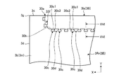
また、本実施形態でも、一例として、面3sに対向したバッテリ6の面ならびに基板7の面は、壁部3mの中心(中心線CL、図11,12参照)を挟んだ両側に亘って、好適にはそれらの面の比較的広い領域同士が、さらに好適には、面3sに対向したバッテリ6の面ならびに基板7の面の端部3c側の端部6a1,7a1と端部3e側の端部6a2,7a2とに亘って、接着されている。よって、一例としては、壁部3mの局所的な曲げが抑制されやすい。さらに、本実施形態では、一例として、バッテリ6が端部3c(第二端部)に寄せて位置され、基板7が端部3e(第一端部)に寄せて位置されている。よって、一例としては、壁部3mが端部3c側から端部3e側に亘るより広い範囲で補強されやすい。また、一例としては、バッテリ6と端部3eとの間の領域S1または基板7と端部3cとの間の領域S2が、他の回路基板(例えば、表示装置4のドライバ基板4c等、図10参照)や配線15等を位置させるのに利用されやすくなる。さらに、本実施形態では、一例として、バッテリ6あるいは基板7は、端部3cまたは端部3eとの間に隙間をあけて位置されている。よって、本実施形態によれば、一例としては、より手指等が当たりやすい端部3c,3eがバッテリ6あるいは基板7で生じた熱によって、暖められるのが抑制されやすい。そして、図11から明らかとなるように、本実施形態では、一例として、壁部3mの中心線CLを含む中央部に、端部3c,3eに沿った方向の一方側(端部3d側)から他方側(端部3f側)に亘って、電気部品が接着された領域Arが形成される。よって、本実施形態によれば、一例としては、第二部材3Rrの壁部3mひいては筐体3Bの剛性および強度がより向上されやすい。
Also in the present embodiment, as an example, the surface of the battery 6 and the surface of the substrate 7 facing the surface 3s extend across both sides of the center of the wall 3m (center line CL, see FIGS. 11 and 12). Preferably, the relatively wide areas of these surfaces are more preferably the surfaces of the battery 6 facing the surface 3s and the ends 6a1 and 7a1 on the end 3c side of the surface of the substrate 7 and the end 3e side. The ends 6a2 and 7a2 are bonded. Therefore, as an example, local bending of the wall 3m is likely to be suppressed. Furthermore, in this embodiment, as an example, the battery 6 is positioned close to the end 3c (second end), and the substrate 7 is positioned close to the end 3e (first end). Therefore, as an example, the wall 3m is easily reinforced in a wider range from the end 3c side to the end 3e side. Further, as an example, the region S1 between the battery 6 and the end 3e or the region S2 between the substrate 7 and the end 3c may be another circuit board (for example, the driver board 4c of the display device 4 or the like). 10) or the wiring 15 and the like. Furthermore, in this embodiment, as an example, the battery 6 or the substrate 7 is positioned with a gap between the end 3c or the end 3e. Therefore, according to the present embodiment, as an example, it is easy to suppress the end portions 3c and 3e that are more likely to be touched by fingers and the like due to heat generated by the battery 6 or the substrate 7 from being heated. As is apparent from FIG. 11, in this embodiment, as an example, one side in the direction along the end portions 3c and 3e (on the end portion 3d side) is provided in the center portion including the center line CL of the wall portion 3m. A region Ar to which the electrical components are bonded is formed from the other side (the end 3f side) to the other side. Therefore, according to the present embodiment, as an example, the rigidity and strength of the wall 3m of the second member 3Rr, and thus the housing 3B, can be improved more easily.
また、本実施形態では、一例として、図11,12,14,16に示されるように、第二部材3Rrの端部3cには、U字状の切欠部30aが設けられている。この切欠部30aには、導電性の低い材料(非導電性材料、絶縁性材料、例えば合成樹脂材料等)で構成された第三部材3Isが取り付けられている。第三部材3Isは、第二部材3Rrの壁部3mの切欠部30aに、熱溶着等によって結合されている。また、図14に示されるように、壁部3mの切欠部30aの縁部30bには、凹部30cおよび凸部30dが設けられている。凹部30cは、縁部30b側(開放側)で幅が狭い第一部30c1と、奥側で幅が広い第二部30c2と、を有する。図16に示されるように、凹部30cの深さは、壁部2mの厚さ方向の途中までである。また、切欠部30aの縁部30bには、凹部30cの裏側に、段差部32eが設けられている。段差部32eは、例えば、縁部30bに沿って延びている。よって、この部分では、第三部材3Isの凹部30cに充填された第一部33aと、第三部材3Isの段差部32eに充填された第二部33bとによって、縁部30bが、壁部3mの厚さ方向(筐体3Bの厚さ方向)に挟まれている。凸部30dは、隣接した二つの凹部30c間に構成されている。これにより、第三部材3Isが、切欠部30aからX方向、Y方向、およびZ方向の三方向に抜けにくく、外力等が作用した場合等にあっても第三部材3Isと第二部材3Rrとが外れにくい構造が得られている。また、図14に示されるように、縁部30bに設けられた屈曲部32f(曲部、角部、隅部、凹部、凸部)によっても、第二部材3Rrと第三部材3Isとが外れにくくなる。
In the present embodiment, as an example, as shown in FIGS. 11, 12, 14, and 16, a U-shaped notch 30 a is provided at the end 3 c of the second member 3 </ b> Rr. A third member 3Is made of a material having low conductivity (a non-conductive material, an insulating material such as a synthetic resin material) is attached to the notch 30a. The third member 3Is is coupled to the notch 30a of the wall 3m of the second member 3Rr by heat welding or the like. Further, as shown in FIG. 14, a concave portion 30c and a convex portion 30d are provided on the edge portion 30b of the cutout portion 30a of the wall portion 3m. The recess 30c has a first portion 30c1 that is narrow on the edge 30b side (open side) and a second portion 30c2 that is wide on the back side. As FIG. 16 shows, the depth of the recessed part 30c is to the middle of the thickness direction of the wall part 2m. Further, a step portion 32e is provided on the edge 30b of the notch 30a on the back side of the recess 30c. The step portion 32e extends, for example, along the edge portion 30b. Therefore, in this portion, the edge portion 30b becomes the wall portion 3m by the first portion 33a filled in the concave portion 30c of the third member 3Is and the second portion 33b filled in the step portion 32e of the third member 3Is. In the thickness direction (thickness direction of the housing 3B). The convex part 30d is configured between two adjacent concave parts 30c. Thereby, the third member 3Is and the second member 3Rr are not easily removed from the notch 30a in the three directions of the X direction, the Y direction, and the Z direction, and an external force or the like is applied. The structure is difficult to come off. Further, as shown in FIG. 14, the second member 3Rr and the third member 3Is are also separated by the bent portion 32f (curved portion, corner portion, corner portion, concave portion, convex portion) provided on the edge portion 30b. It becomes difficult.
また、本実施形態では、一例として、図11,12,15に示されるように、導電性の低い材料で構成された第三部材3Isに、アンテナモジュール13およびカメラモジュール10が取り付けられている。このような構成により、導電性材料が電磁シールドとなってアンテナモジュール13の通信に影響が及ぶのが抑制されやすい。また、図15に示されるように、後面3b側には、カバー(プレート)10aが設けられ、このカバー10aを介して、カメラモジュール10のレンズ10bおよびライト10cが露出されている。
In the present embodiment, as an example, as shown in FIGS. 11, 12, and 15, the antenna module 13 and the camera module 10 are attached to a third member 3Is made of a material having low conductivity. With such a configuration, it is easy to suppress the conductive material from becoming an electromagnetic shield and affecting the communication of the antenna module 13. Further, as shown in FIG. 15, a cover (plate) 10a is provided on the rear surface 3b side, and the lens 10b and the light 10c of the camera module 10 are exposed through the cover 10a.
また、本実施形態では、一例として、図11,12に示されるように、アンテナモジュール13は、通信部13aとグラウンド部13bとを有する。そして、グラウンド部13bの一部が、バッテリ6と第二部材3Rrの壁部3mとの間に挟まれている。グラウンド部13bは、壁部3mと電気的に接続された場合、グラウンド部13bと壁部3mとでグラウンドレベル(電位)を近付けることができ、アンテナモジュール13へのノイズの混入が低減されやすい。また、アンテナモジュール13のグラウンド部13bとバッテリ6の外皮とのグラウンドレベル(電位)が近付きやすい。
In the present embodiment, as an example, as shown in FIGS. 11 and 12, the antenna module 13 includes a communication unit 13a and a ground unit 13b. A part of the ground portion 13b is sandwiched between the battery 6 and the wall portion 3m of the second member 3Rr. When the ground part 13b is electrically connected to the wall part 3m, the ground part 13b and the wall part 3m can bring the ground level (potential) close to each other, and mixing of noise into the antenna module 13 is easily reduced. In addition, the ground level (potential) between the ground portion 13 b of the antenna module 13 and the outer skin of the battery 6 tends to approach.
また、本実施形態では、一例として、図11,12に示されるように、カメラモジュール10に電気的に接続される配線15a(15)が、フレキシブルプリント配線板として構成され、バッテリ6と筐体3Bの厚さ方向に重なっている。よって、本実施形態によれば、一例としては、配線15aが電磁シールドとなってアンテナモジュール13の通信に影響が及ぶのが、抑制されやすい。また、本実施形態では、一例として、図11,12に示されるように、配線15aは、バッテリ6の縁部に沿って延びている。よって、本実施形態によれば、一例としては、配線15aを、温度が高くなりやすいバッテリ6の中央部から外れて配置することができる。
In this embodiment, as an example, as shown in FIGS. 11 and 12, the wiring 15a (15) electrically connected to the camera module 10 is configured as a flexible printed wiring board, and the battery 6 and the housing It overlaps in the thickness direction of 3B. Therefore, according to this embodiment, as an example, it is easy to suppress the wiring 15a from being an electromagnetic shield and affecting the communication of the antenna module 13. In the present embodiment, as an example, as shown in FIGS. 11 and 12, the wiring 15 a extends along the edge of the battery 6. Therefore, according to the present embodiment, as an example, the wiring 15a can be arranged away from the center of the battery 6 where the temperature tends to be high.
また、本実施形態でも、図17,18に示されるように、上記第1実施形態と同様に、第二部材3Rrは、組み立てられた状態での第一部材3Frの壁部3nの筐体内側で壁部3mから壁部3nに沿って突出した突出部3t(第四突出部)を有している。突出部3tに設けられた係部31a(第一係部)と壁部3nに設けられた係部31b(第二係部)とが筐体3Bの厚さ方向(Z方向)に係わっている。本実施形態では、一例として、係部31aは貫通孔として構成され、係部31bは爪部(突出部、突起)として構成されている。これら係部31aと係部31bとの係わりによって、第一部材3Frと第二部材3Rrとが結合されている。このように、本実施形態では、一例として、比較的簡素な構成によって、第一部材3Frと第二部材3Rrとが結合されている。
Also in this embodiment, as shown in FIGS. 17 and 18, as in the first embodiment, the second member 3 </ b> Rr is inside the housing of the wall portion 3 n of the first member 3 </ b> Fr in the assembled state. And a protrusion 3t (fourth protrusion) protruding from the wall 3m along the wall 3n. The engaging portion 31a (first engaging portion) provided on the protruding portion 3t and the engaging portion 31b (second engaging portion) provided on the wall 3n are engaged in the thickness direction (Z direction) of the housing 3B. . In the present embodiment, as an example, the engaging portion 31a is configured as a through hole, and the engaging portion 31b is configured as a claw portion (protruding portion, protrusion). The first member 3Fr and the second member 3Rr are coupled by the engagement between the engagement portion 31a and the engagement portion 31b. Thus, in the present embodiment, as an example, the first member 3Fr and the second member 3Rr are coupled with a relatively simple configuration.
また、本実施形態でも、図18に示されるように、上記第1実施形態と同様に、第二部材3Rrは、組み立てられた状態での第一部材3Frの壁部3nの筐体内側で壁部3mから壁部3nに沿って突出した突出部3u(第一突出部)を有している。突出部3uの筐体内側には、リブ3v(突出部)が設けられている。また、図17に示されるように、第一部材3Frは、組み立てられた状態で突出部3uを壁部3nとの間に挟んだ状態で、壁部3kから壁部3mに向けて(Z方向に沿って)突出した突出部3w(第二突出部、壁部)を有している。すなわち、突出部3wは、壁部3nとの間に突出部3uを受け容れ可能な隙間(一例としては突出部3uの厚さより僅かに広い隙間)をもって突出している。さらに、第一部材3Frは、突出部3uと壁部3k,3mの周縁に沿った方向(表示装置4の周縁に沿った方向、図17,18ではY方向)に係わって壁部3kから壁部3mに向けて突出した二つの突出部3x(第三突出部、壁部)を有している。すなわち、二つの突出部3xは、それらの間に突出部3uを受け容れ可能な隙間(一例としては突出部3uの幅より僅かに広い隙間)をもって突出している。本実施形態では、一例として、第一部材3Frと第二部材3Rrとが組み立てられた状態では、突出部3uは、壁部3nと突出部3wとの間にX方向に挟まれるとともに、二つの突出部3xによってY方向に挟まれる。図17に示されるように、突出部3w,3x(壁部)は、互いにC字状に接続されるとともに、さらに壁部3nに接続されている。すなわち、壁部3nおよび突出部3w,3xによって、筒状(角筒状、環状)の収容部が設けられている。このような構成により、本実施形態では、一例として、第二部材3Rrに設けられた突出部3uが第一部材3Frに対して、壁部3nの厚さ方向(図17,18の例ではY方向)や壁部3nに沿った長手方向(図17,18の例ではX方向)に移動するのが抑制される。よって、本実施形態によれば、一例としては外力等によって第一部材3Frと第二部材3Rrとが互いに接触する縁部で離間するのが、比較的簡素な構成によって抑制されやすい。なお、突出部3wには、組み立てられた状態で、リブ3vを受け容れる切欠部3y(凹部)が設けられている。よって、突出部3wのうち切欠部3yの縁部も、突出部3xと同様に、第三突出部として機能する。
Also in the present embodiment, as shown in FIG. 18, as in the first embodiment, the second member 3Rr is a wall inside the housing of the wall portion 3n of the first member 3Fr in the assembled state. It has the protrusion part 3u (1st protrusion part) which protruded along the wall part 3n from the part 3m. A rib 3v (protrusion) is provided inside the housing of the protrusion 3u. Also, as shown in FIG. 17, the first member 3Fr is in an assembled state with the protruding portion 3u sandwiched between the wall portion 3n and from the wall portion 3k to the wall portion 3m (Z direction). Along the projection 3w (second projection, wall). That is, the protruding portion 3w protrudes with a gap (for example, a gap slightly wider than the thickness of the protruding portion 3u) that can receive the protruding portion 3u between the wall portion 3n. Further, the first member 3Fr is engaged with the wall from the wall 3k in the direction along the periphery of the protrusion 3u and the walls 3k, 3m (the direction along the periphery of the display device 4, the Y direction in FIGS. 17 and 18). It has two protrusions 3x (third protrusion, wall) protruding toward the part 3m. That is, the two protrusions 3x protrude with a gap (for example, a gap slightly wider than the width of the protrusion 3u) that can receive the protrusion 3u between them. In the present embodiment, as an example, in a state where the first member 3Fr and the second member 3Rr are assembled, the protrusion 3u is sandwiched in the X direction between the wall 3n and the protrusion 3w, and two It is sandwiched in the Y direction by the protrusion 3x. As shown in FIG. 17, the protrusions 3w and 3x (wall portions) are connected to each other in a C shape and are further connected to the wall portion 3n. That is, a cylindrical (square cylindrical, annular) accommodating portion is provided by the wall portion 3n and the protruding portions 3w and 3x. With such a configuration, in the present embodiment, as an example, the protrusion 3u provided on the second member 3Rr is in the thickness direction of the wall 3n with respect to the first member 3Fr (Y in the examples of FIGS. 17 and 18). Direction) and the longitudinal direction along the wall 3n (X direction in the examples of FIGS. 17 and 18) are suppressed. Therefore, according to the present embodiment, as an example, the first member 3Fr and the second member 3Rr are easily separated from each other at the edge where they are in contact with each other by an external force or the like with a relatively simple configuration. The protruding portion 3w is provided with a notch 3y (recessed portion) that receives the rib 3v in an assembled state. Therefore, the edge part of the notch part 3y also functions as a 3rd protrusion part similarly to the protrusion part 3x among the protrusion parts 3w.
また、本実施形態では、一例として、図19,20に示されるように、筐体3Bの角部3g〜3j(図19,20には角部3jのみ図示)にも、突出部3u(第一突出部)、リブ3v、突出部3w(第二突出部)、および突出部3x(第三突出部)が設けられている。よって、本実施形態によれば、一例としては、筐体3Bの角部において、第一部材3Frと第二部材Rrとが離間しにくい。また、本実施形態では、一例として、図20に示されるように、突出部3uは、壁部3mの角部3jの縁部に沿って弧状に曲がった状態で壁部3mから壁部3k側に向けて突出した壁部30eに接続されている。よって、本実施形態によれば、一例としては、突出部3uの剛性および強度がより高まりやすい。また、壁部30eに対して壁部3mの中心側、すなわち、角部3jあるいは端部3c,3fに対して隙間をあけた位置に、壁部30eと並行して弧状に曲がって延びて壁部3k側に向けて突出した突出部30fが設けられている。さらに、壁部3mには、突出部30f(リブ、第一リブ)と壁部30eとに亘る突出部30g(リブ、第二リブ)が設けられている。他の角部3g〜3iの構成も、図19,20と同様である。よって、本実施形態によれば、一例としては、電子機器1Bの落下時等に他の部分に比べて外力が作用しやすい角部3g〜3jにおいて、突出部3uの剛性および強度がより高まりやすい。
In the present embodiment, as an example, as shown in FIGS. 19 and 20, the protrusion 3 u (the first part is also shown in the corners 3 g to 3 j of the housing 3 B (only the corner 3 j is shown in FIGS. 19 and 20)). One protrusion), a rib 3v, a protrusion 3w (second protrusion), and a protrusion 3x (third protrusion). Therefore, according to the present embodiment, as an example, the first member 3Fr and the second member Rr are not easily separated from each other at the corners of the housing 3B. In the present embodiment, as an example, as shown in FIG. 20, the protrusion 3 u is bent from the wall 3 m to the wall 3 k side in an arcuate shape along the edge of the corner 3 j of the wall 3 m. It is connected to the wall part 30e which protruded toward. Therefore, according to the present embodiment, as an example, the rigidity and strength of the protrusion 3u are more likely to increase. Further, the wall 30e extends in a curved manner in parallel with the wall 30e at the center side of the wall 3m, that is, at a position where a gap is formed between the corner 3j or the ends 3c and 3f. A projecting portion 30f projecting toward the portion 3k is provided. Further, the wall 3m is provided with a protruding portion 30g (rib, second rib) extending between the protruding portion 30f (rib, first rib) and the wall 30e. The configurations of the other corner portions 3g to 3i are the same as those in FIGS. Therefore, according to the present embodiment, as an example, the rigidity and strength of the protruding portion 3u are more likely to increase at the corner portions 3g to 3j where the external force is more likely to act than other portions when the electronic device 1B is dropped. .
また、本実施形態では、一例として、図21に示されるように、壁部3nには、図22に示された端部3fに沿って並んだコネクタ16a〜16dを筐体3B外に露出させる開口部30h〜30kが、貫通孔として設けられている。よって、本実施形態によれば、一例としては、開口部30h〜30kが切欠等として設けられた場合に比べて、壁部3nの剛性および強度が高まりやすい。また、図22において、コネクタ16aは、カードが着脱可能に装着(接続、保持)されるカード用のコネクタであり、コネクタ16b〜16dは、別のコネクタが着脱可能に装着(接続、保持)されるコネクタである。コネクタ16b,16c等の端子(突起、支持部、脚部、突出部、図示されず)は、基板7の厚さ方向には貫通せず、厚さ方向の途中までの長さを有する。よって、コネクタ16b,16c等の端子が基板7と壁部3mとの接着(密着)を阻害するのが抑制される。また、コネクタ16b,16c等(の開口部)の基板7からの高さを適宜に設定することで、コネクタ16b,16c等と壁部3nの中間位置に設けられた部材32cとが、端部3c〜3fの沿った方向(図21ではY方向)に並べる(近付けて配置する)ことができる。また、コネクタ16aとコネクタ16bとの間、ならびにコネクタ16dとコネクタ16dとの間には、突出部3tが設けられ、この突出部3tには、係部31aが設けられている。貫通孔としての係部31aは、開口面積が開放側(出口側、開口端側)に向かうにつれて拡がっている。すなわち、係部31aは、出口側の端部に向かうにつれて、貫通孔の中心線から遠ざかる側面(内面、内周面、筒内面)を有している。
Further, in the present embodiment, as an example, as illustrated in FIG. 21, connectors 16a to 16d arranged along the end 3f illustrated in FIG. 22 are exposed to the outside of the housing 3B on the wall 3n. Openings 30h to 30k are provided as through holes. Therefore, according to the present embodiment, as an example, the rigidity and strength of the wall 3n are likely to be higher than when the openings 30h to 30k are provided as notches or the like. In FIG. 22, a connector 16a is a connector for a card to which a card is detachably attached (connected and held), and another connector is detachably attached (connected and held) to the connectors 16b to 16d. Connector. Terminals (projections, support portions, leg portions, protruding portions, not shown) such as the connectors 16b and 16c do not penetrate in the thickness direction of the substrate 7 and have a length up to the middle in the thickness direction. Therefore, it is suppressed that terminals, such as connectors 16b and 16c, inhibit adhesion (adhesion) between substrate 7 and wall part 3m. Further, by appropriately setting the height of the connectors 16b, 16c and the like (opening thereof) from the substrate 7, the member 32c provided at the intermediate position between the connectors 16b, 16c and the wall portion 3n is connected to the end portion. They can be arranged (closely arranged) in the direction along 3c to 3f (the Y direction in FIG. 21). Further, a protruding portion 3t is provided between the connector 16a and the connector 16b, and between the connector 16d and the connector 16d, and an engaging portion 31a is provided on the protruding portion 3t. The engaging portion 31a as the through hole is expanded as the opening area is directed toward the open side (exit side, opening end side). That is, the engaging portion 31a has side surfaces (an inner surface, an inner peripheral surface, and a cylindrical inner surface) that move away from the center line of the through hole as it goes toward the end portion on the outlet side.
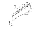
また、本実施形態では、一例として、図23に示されるように、第一部材3Frの壁部3nには、端部3dに沿って延びた部材30mが設けられている。部材30mは、第一部材3Frより硬い材質(一例としては金属材料)で構成されている。よって、本実施形態によれば、一例としては、壁部3nの剛性および強度がより高まりやすい。なお、図23に例示された部材30mは、スピーカモジュール11に面して設けられており、開口部30nが設けられている。この開口部30nにより、スピーカモジュール11の音が筐体3Bの外に出やすくなる。すなわち、部材30mは、スピーカモジュール11のカバーの一例である。また、第一部材3Frの壁部3kには、スピーカモジュール11が収容される切欠部30pが設けられている。よって、本実施形態によれば、一例としては、切欠部30pによって当該切欠部30pが設けられていない部分に比べて剛性あるいは強度が低くなった部分を、部材30mによって補強することができる。
In the present embodiment, as an example, as shown in FIG. 23, a wall 30n of the first member 3Fr is provided with a member 30m extending along the end 3d. The member 30m is made of a material harder than the first member 3Fr (for example, a metal material). Therefore, according to this embodiment, as an example, the rigidity and strength of the wall 3n are more likely to increase. Note that the member 30m illustrated in FIG. 23 is provided facing the speaker module 11, and is provided with an opening 30n. The opening 30n makes it easier for the sound of the speaker module 11 to go out of the housing 3B. That is, the member 30m is an example of a cover of the speaker module 11. Further, the wall 3k of the first member 3Fr is provided with a notch 30p in which the speaker module 11 is accommodated. Therefore, according to the present embodiment, as an example, the member 30m can reinforce the portion whose rigidity or strength is lower than the portion where the notch 30p is not provided by the notch 30p.
以上の第2実施形態にかかる電子機器1Bにおいても、上記第1実施形態にかかるテレビジョン受像機1Aと同様の構成を有することによる同様の効果が得られる。
Also in the electronic apparatus 1B according to the second embodiment described above, the same effect is obtained by having the same configuration as the television receiver 1A according to the first embodiment.
以上、本発明の実施形態を例示したが、上記実施形態はあくまで一例であって、発明の範囲を限定することは意図していない。これら実施形態は、その他の様々な形態で実施されることが可能であり、発明の要旨を逸脱しない範囲で、種々の省略、置き換え、組み合わせ、変更を行うことができる。これら実施形態やその変形は、発明の範囲や要旨に含まれるとともに、特許請求の範囲に記載された発明とその均等の範囲に含まれる。本発明は上記実施形態には限定されず、種々の変形が可能である。一例としては、図24に示される変形例にかかる電子機器1Cのように、筐体3Cを構成する第一部材3Frの端部32aを入力操作パネル5の面5aより突出させることができる。この場合、突出した端部32aによって、入力操作パネル5や表示装置4が保護されやすい。また、上記各実施形態の技術的特徴は、適宜に組み合わせたり置換したりして実施することができる。また、各構成要素のスペック(構造や、種類、方向、形状、大きさ、長さ、幅、厚さ、高さ、数、配置、位置、材質等)は、適宜に変更して実施することができる。
As mentioned above, although embodiment of this invention was illustrated, the said embodiment is an example to the last, Comprising: It is not intending limiting the range of invention. These embodiments can be implemented in various other forms, and various omissions, replacements, combinations, and changes can be made without departing from the scope of the invention. These embodiments and modifications thereof are included in the scope and gist of the invention, and are included in the invention described in the claims and the equivalents thereof. The present invention is not limited to the above embodiment, and various modifications are possible. As an example, the end 32a of the first member 3Fr constituting the housing 3C can be protruded from the surface 5a of the input operation panel 5 as in the electronic device 1C according to the modification shown in FIG. In this case, the input operation panel 5 and the display device 4 are easily protected by the protruding end portion 32a. The technical features of the above embodiments can be implemented by appropriately combining or replacing them. In addition, the specifications of each component (structure, type, direction, shape, size, length, width, thickness, height, number, arrangement, position, material, etc.) should be changed as appropriate. Can do.