JP5242014B2 - CPF pulse shaper - Google Patents
CPF pulse shaper Download PDFInfo
- Publication number
- JP5242014B2 JP5242014B2 JP2006047345A JP2006047345A JP5242014B2 JP 5242014 B2 JP5242014 B2 JP 5242014B2 JP 2006047345 A JP2006047345 A JP 2006047345A JP 2006047345 A JP2006047345 A JP 2006047345A JP 5242014 B2 JP5242014 B2 JP 5242014B2
- Authority
- JP
- Japan
- Prior art keywords
- cpf
- pulse
- wavelength
- dispersion
- nzdsf
- Prior art date
- Legal status (The legal status is an assumption and is not a legal conclusion. Google has not performed a legal analysis and makes no representation as to the accuracy of the status listed.)
- Active
Links
Images


Description
本発明は、光ファイバ通信システムにおける光パルス発生技術に適用されるCPFパルス成型器の技術分野に関するものであり、特にCLバンド(1530〜1610nm)の波長帯で波長可変なCPFパルス成型器の技術分野に関するものである。 The present invention relates to a technical field of a CPF pulse shaper applied to an optical pulse generation technology in an optical fiber communication system, and in particular, a technology of a CPF pulse shaper that is tunable in a CL band (1530 to 1610 nm) wavelength band. It is related to the field.
非線形媒体である高非線形ファイバ(HNLF)と、分散媒体である異常分散ファイバ(例えばシングルモードファイバ;SMF)とを交互に組み合わせて構成されるCPFパルス成型器に関しては、これまでに様々な技術開発が行われてきている。上記のように構成されたCPFパルス成型器は、ファイバの非線形定数と分散値の両方が長手方向に櫛状のプロファイルを形成していることから、Comb-like Profiled Fiber(CPF)パルス成型器と呼ばれている。 Various technologies have been developed so far for CPF pulse shapers composed of alternating combinations of highly nonlinear fiber (HNLF), which is a nonlinear medium, and anomalous dispersion fiber (for example, single mode fiber; SMF), which is a dispersion medium. Has been done. The CPF pulse shaper configured as described above has a comb-like profiled fiber (CPF) pulse shaper because both the nonlinear constant and dispersion value of the fiber form a comb-like profile in the longitudinal direction. being called.
CPFパルス成型器の特徴は、全長が短いにもかかわらず、高効率で高品質なパルス成形が可能なことである。ここでいう高品質なパルス成形とは、高次ソリトン圧縮の際に生じるような、ペデスタル増大現象や変調不安定利得による著しい雑音増幅現象、及びそれに伴うタイミングジッタ付加が発生しないパルス成形を意味する。 A feature of the CPF pulse shaper is that it is capable of high-efficiency and high-quality pulse shaping despite its short overall length. High-quality pulse shaping here means pulse shaping that does not cause pedestal increase phenomenon, significant noise amplification phenomenon due to modulation instability gain, and accompanying timing jitter, which occurs during high-order soliton compression. .
CPFパルス成型器の設計方法として、例えば非特許文献1に示されている方法を用いることができる。非特許文献1の方法によれば、高精度な光パルス列を出力可能なCPFパルス成型器を容易に設計することができる。
As a design method of the CPF pulse shaper, for example, the method shown in Non-Patent
光ファイバの分散特性は、通常、波長によって異なり,同じファイバ長での累積分散量も波長によって異なってしまう。
前記累積分散量は、設計値にある程度近くなければならないが,分散特性が波長によって変化すると、波長が設計上の中心波長から離れるに従って、累積分散量も設計値から離れていくことになる。そして、累積分散量が所定の誤差以上となる波長に対しては、CPFパルス成型器は正常に動作しなくなる。
The dispersion characteristic of an optical fiber usually varies depending on the wavelength, and the accumulated dispersion amount at the same fiber length also varies depending on the wavelength.
The cumulative dispersion amount must be close to a design value to some extent, but when the dispersion characteristic changes depending on the wavelength, the cumulative dispersion amount is also away from the design value as the wavelength is away from the design center wavelength. Then, the CPF pulse shaper does not operate normally for wavelengths where the accumulated dispersion amount exceeds a predetermined error.
非特許文献1に示されている方法を用いて設計されたCPFパルス成型器においても、動作波長によってCPFパルス成型器の累積分散量が変化すれば、広帯域の動作波長に対して同一設計および同一入力条件に対して同じ特性のパルス成型が実現できなくなるという問題があった。
Even in a CPF pulse shaper designed using the method shown in Non-Patent
そこで非特許文献2に記載の実施例では、HNLFとSMFとを組み合わせた従来構成のCPFパルス成型器において、入力パワーを調整することにより、すべての波長帯で同等の出力パルス幅が得られるようにしている。ここで報告されているCPFパルス成型器は、1570nmでパルス圧縮動作が最適化されるように設計されており、CLバンド(1530~1610nm)の波長帯で波長可変としている。入力パルスは40GHz繰り返しRZ(Return-to-Zero)パルス列を用いており、8.5psの入力パルス幅を1.8psに圧縮している。
Therefore, in the embodiment described in Non-Patent
上記従来の技術は、ピコ秒オーダーで光パルスを成型するものであったが、最近ではさらにフェムト秒オーダーの光源の利用ニーズも高まっている。例えば、各種科学技術研究の分野や、エネルギーを大きくして二光子吸収などのプロセスによる加工分野での利用がある。 Although the above conventional technique forms an optical pulse on the order of picoseconds, the need for using a light source on the order of femtoseconds has recently increased. For example, it is used in the fields of various scientific and technological researches and in the field of processing by processes such as two-photon absorption by increasing energy.
フェムト秒パルス光源として、従来は主にモードロックレーザが用いられていたが、これは比較的特性が不安定で、パルス繰り返し周波数や発振波長が固定されてしまうといった問題があった。そこで、非特許文献4に示されているように、分散フラット・分散減少ファイバを用いることにより、Cバンドにおける波長可変フェムト秒圧縮を実現した例がすでに知られている。
Conventionally, a mode-locked laser has been mainly used as a femtosecond pulse light source. However, this has a problem that the characteristics are relatively unstable and the pulse repetition frequency and the oscillation wavelength are fixed. Thus, as shown in
一方、波長変化に対する分散特性の変化量がきわめて小さいファイバの開発も進められており、例えば非特許文献3では、分散値D[ps/nm/km]の波長λ[nm]に対する変化量を示す、分散スロープの値が零である分散シフトファイバ(Zero-slope non-zero dispersion-shifted fiber; ZS-NZDSF)の開発について報告されている。但し、ZS-NZDSFをCPFパルス成型器に適用した実施例はこれまでに見られない。
しかしながら、上記従来のCPFパルス成型器では、以下のような課題があった。
従来の構成、すなわちHNLFとSMFを組み合わせた構成で、1570nmでパルス圧縮動作が最適化されるようにCPFを設計した場合、入力パワーを調整することにより、すべての波長帯で同等の出力パルス幅が得られる。ただし、パワーの調整幅が全体で2~2.5dBの範囲に及び、さらにペデスタル等のパルス品質が波長依存性を示す(具体的には、設計波長より短波長ではペデスタルが増大し、長波側ではそれが抑圧される)という問題が発生していた。願わくは、すべての波長で同じ動作パワーで、出力パルス品質も波長無依存となるのが好ましい。
However, the conventional CPF pulse shaper has the following problems.
When the CPF is designed to optimize the pulse compression operation at 1570 nm with the conventional configuration, that is, the combination of HNLF and SMF, by adjusting the input power, the same output pulse width in all wavelength bands Is obtained. However, the power adjustment range is in the range of 2 to 2.5 dB as a whole, and pulse quality such as pedestal shows wavelength dependence (specifically, the pedestal increases at shorter wavelengths than the design wavelength, and on the long wave side The problem that it was suppressed) occurred. Preferably, it is preferable that the output pulse quality is independent of wavelength with the same operating power at all wavelengths.
この問題は主に、SMFの分散値が、光の波長もしくは周波数に対して変化することに起因する。光ファイバの分散値の表し方は二通りあって、D [ps/nm/km]とβ2 [ps2/km]であり、それぞれの値には
![]()
![]()
という関係がある。ここでλは波長、cは真空中の光速である。Dとβ2のうち、ファイバ中の光パルス伝搬特性を決める普遍的な量は、β2である。つまり同じβ2の値であれば、任意の波長λで分散の強さは同じであるが、一方で、あるDの値が示す分散の強さは、波長λに依存する。SMFの分散値β2は典型値として、波長が1570nmのときにβ2 = -22.8 [ps2/km]である。またλ = 1530nmのときはβ2 = -18.8 [ps2/km]、λ = 1610nmのときはβ2 = -27.2 [ps2/km]である。このように、SMFの分散値が波長によって変化することから、CPFにおけるパルス成型特性は、波長によって変化することになる。 There is a relationship. Where λ is the wavelength and c is the speed of light in vacuum. Of D and β 2 , β 2 is the universal amount that determines the propagation characteristics of optical pulses in the fiber. That is, if the value of β 2 is the same, the intensity of dispersion is the same at an arbitrary wavelength λ, but the intensity of dispersion indicated by a value of D depends on the wavelength λ. The SMF dispersion value β 2 is typically β 2 = −22.8 [ps 2 / km] when the wavelength is 1570 nm. When λ = 1530 nm, β 2 = −18.8 [ps 2 / km], and when λ = 1610 nm, β 2 = −27.2 [ps 2 / km]. As described above, since the dispersion value of the SMF changes depending on the wavelength, the pulse shaping characteristic in the CPF changes depending on the wavelength.
そのため、例えば1.5μm帯の光をSHG(Second Harmonic Generation;2次高調波発生)で800nm帯に波長変換するにあたっても、もとの1.5μm帯においてより広帯域で波長可変圧縮動作するのが望ましいが、従来のCPFを用いる場合はこれを実現するのが困難となる。一方、分散フラット・分散減少ファイバを用いて波長可変なフェムト秒圧縮を行わせる従来の方法では、Cバンドでは実現できるものの、CLバンドの広帯域では四次分散の影響のため波長可変なフェムト秒圧縮を実現することは困難となる。 For this reason, for example, when converting the wavelength of 1.5 μm band light into the 800 nm band by SHG (Second Harmonic Generation), it is desirable to perform the variable wavelength compression operation in a wider band in the original 1.5 μm band. This is difficult to achieve when using a conventional CPF. On the other hand, the conventional method of performing variable wavelength femtosecond compression using a dispersion flat / dispersion decreasing fiber can be realized in the C band, but in the CL band wide band due to the influence of fourth order dispersion, the variable wavelength femtosecond compression. It becomes difficult to realize.
そこで、本発明はこれらの問題を解決するためになされたものであり、CLバンド(1530~1610nm)の波長帯で波長可変であるCPFパルス成型器を提供することを目的とする。 Accordingly, the present invention has been made to solve these problems, and an object thereof is to provide a CPF pulse shaper that is tunable in a CL band (1530 to 1610 nm) wavelength band.
この発明のCPFパルス成型器の第1の態様は、非線形媒体と分散媒体とを交互に複数組み合わせて構成されるCPF(Comb-like Profiled Fiber) を備えたCPFパルス成型器であって、所定の波長λ0[nm]における分散値をβ20[ps2 /km]とし、所定の波長範囲λ0±Δλにおける分散値とβ20との差の絶対値の最大値をΔβ2としたとき、波長の変化幅Δλ=40[nm]に対して|Δβ 2 /β 20 |=0.193となるシングルモードファイバ(SMF)と比較して、前記分散媒体の一部または全部が、前記所定の波長範囲λ0±Δλにおける|Δβ2 /β20|が前記SMFより小さい値を有することを特徴とするCPFパルス成型器である。 A first aspect of the CPF pulse shaper according to the present invention is a CPF pulse shaper provided with a CPF (Comb-like Profiled Fiber) configured by alternately combining a plurality of nonlinear media and dispersion media. When the dispersion value at the wavelength λ 0 [nm] is β 20 [ps 2 / km], and the maximum absolute value of the difference between the dispersion value and β 20 in the predetermined wavelength range λ 0 ± Δλ is Δβ 2 , Compared to a single mode fiber (SMF) in which | Δβ 2 / β 20 | = 0.193 for a wavelength change width Δλ = 40 [nm], a part or all of the dispersion medium is a CPF pulse reshaping device which is characterized by having the SMF smaller value | definitive in the wavelength range λ 0 ± Δλ | Δβ 2 / β 20.
この発明のCPFパルス成型器の第2の態様は、前記所定の波長範囲λ 0 ±Δλの光パルスを出射して前記CPFに入射するパルス光源を備えることを特徴とするCPFパルス成型器である。 A second aspect of the CPF pulse shaper of the present invention is a CPF pulse shaper comprising a pulse light source that emits an optical pulse in the predetermined wavelength range λ 0 ± Δλ and enters the CPF. .
第3の態様は、前記分散媒体の一部または全部が、ノンゼロ分散シフト光ファイバ(ZS-NZDSF;Zero-Slope Non-Zero Dispersion-Shifted Fiber)であることを特徴とするCPFパルス成型器である。 The third aspect, some or all of the dispersing medium is non-zero dispersion shifted optical fiber; is CPF pulse reshaping device which is a (ZS-NZDSF Zero-Slope Non -Zero Dispersion-Shifted Fiber) .
第4の態様は、前記分散媒体の一部が前記ノンゼロ分散シフト光ファイバであり、残りがシングルモードファイバ(SMF)であることを特徴とするCPFパルス成型器である。 A fourth aspect is a CPF pulse shaper characterized in that a part of the dispersion medium is the non- zero dispersion shifted optical fiber and the rest is a single mode fiber (SMF).
第5の態様は、前記CPFの上流側に、所定の長さの別の分散媒体を追加していることを特徴とするCPFパルス成型器である。 A fifth aspect is a CPF pulse shaper characterized in that another dispersion medium having a predetermined length is added upstream of the CPF.
第6の態様は、前記別の分散媒体が、前記所定の波長範囲における|Δβ2 /β20|が波長の変化幅Δλ=40[nm]に対して|Δβ 2 /β 20 |=0.193となるシングルモードファイバ(SMF)より小さい値を有することを特徴とするCPFパルス成型器である。 Sixth aspect, the further dispersion medium is definitive in the predetermined wavelength range | Δβ 2 / β 20 | relative change width Δλ = 40 [nm] wavelength | Δβ 2 / β 20 | = 0 A CPF pulse shaper having a value smaller than a single mode fiber (SMF) of 193 .
第7の態様は、前記別の分散媒体が、ノンゼロ分散シフト光ファイバであることを特徴とするCPFパルス成型器である。 A seventh aspect is a CPF pulse shaper, wherein the another dispersion medium is a non-zero dispersion shifted optical fiber.
第8の態様は、前記所定の波長範囲が、少なくともCバンド及びLバンドを含むことを特徴とするCPFパルス成型器である。
An eighth aspect is the CPF pulse shaper, wherein the predetermined wavelength range includes at least a C band and an L band.
以上説明したように本発明によれば、分散媒体にZS-NZDSFを用いることにより、累積分散量が所定の波長帯域内でほぼ均等となるCPFパルス成型器を提供することできる。 As described above, according to the present invention, by using ZS-NZDSF as a dispersion medium, it is possible to provide a CPF pulse shaper in which the accumulated dispersion amount is substantially uniform within a predetermined wavelength band.
また、前記所定の波長帯域内で波長を変化させる場合には、出力パルスのパルス幅を均等にするための入力パワーの調整幅を従来より大幅に縮小できるとともに、品質が波長依存性のない均一な出力パルスを得ることが可能なCPFパルス成型器を提供することができる。 In addition, when changing the wavelength within the predetermined wavelength band, the adjustment range of the input power for equalizing the pulse width of the output pulse can be greatly reduced as compared with the conventional one, and the quality is uniform without wavelength dependency. It is possible to provide a CPF pulse shaper capable of obtaining a simple output pulse.
さらに、本発明のCPFパルス成型器によれば、CLバンドで波長可変なフェムト秒圧縮を実現することができ、安定で高品質なフェムト秒パルス光源として利用可能となる。 Furthermore, according to the CPF pulse shaper of the present invention, femtosecond compression with variable wavelength in the CL band can be realized, and can be used as a stable and high-quality femtosecond pulse light source.
図面を参照して本発明の好ましい実施の形態におけるCPFパルス成型器の構成について詳細に説明する。なお、同一機能を有する各構成部については、図示及び説明簡略化のため、同一符号を付して示す。 A configuration of a CPF pulse shaper in a preferred embodiment of the present invention will be described in detail with reference to the drawings. In addition, about each structural part which has the same function, the same code | symbol is attached | subjected and shown for simplification of illustration and description.
CPFパルス成型器は、パルスに非線形効果を及ぼすHNLFと、異常分散効果を及ぼすファイバから構成されるが、異常分散ファイバとして従来のSMFの代わりに、分散値β2の波長依存性がSMFより小さいファイバ、あるいはβ2が波長に依存しないファイバを用いれば、CPF動作特性の波長依存性は抑圧、もしくは解消される。例えば、ある波長において分散スロープが零で、分散値が異常分散領域である、ゼロスロープ分散シフトファイバ(Zero-slope dispersion-shifted fiber; ZS-NZDSF)が報告されているが、そのようなファイバを用いればよい。 The CPF pulse shaper is composed of HNLF, which has a nonlinear effect on the pulse, and fiber, which has an anomalous dispersion effect. However, the wavelength dependence of the dispersion value β 2 is smaller than SMF instead of the conventional SMF as an anomalous dispersion fiber. If a fiber or a fiber whose β 2 does not depend on the wavelength is used, the wavelength dependence of the CPF operating characteristics is suppressed or eliminated. For example, zero-slope dispersion-shifted fiber (ZS-NZDSF), which has zero dispersion slope and anomalous dispersion at a certain wavelength, has been reported. Use it.
ここで分散スロープとは、分散値D[ps/nm/km]が波長λ[nm]に対して線形に変化する割合を示すもので、スロープ値はS[ps/nm2/km] = dD/dλで定義される。また、β2の周波数依存性を示す値として、β2の周波数ωによる一階微分で定義されるβ3 = dβ2/dωが用いられるが、ある波長λにおいて、Sとβ3は次の関係にある。
![]()
![]()
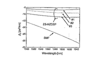
分散スロープ値Sが零の場合でも、β3は一般に零とならないが、Sが小さいファイバであれば、傾向としてβ2の波長依存性は小さくなる。SMFおよび非特許文献3で報告されているZS-NZDSFの、波長λ[nm]に対する分散値D[ps/nm/km]およびβ2 [ps2/km]の値を図1と2に示す。図1から、ZS-NZDSFはSMFより分散スロープ値Sの絶対値が小さく、ある波長においてはスロープ値Sが零となっている。また図2においてSMFと比較して、ZS-NZDSFのβ2の波長依存性が小さいことがわかる。
Even when the dispersion slope value S is zero, β 3 generally does not become zero. However, if the fiber has a small S, the wavelength dependency of β 2 tends to be small. 1 and 2 show the dispersion values D [ps / nm / km] and β 2 [ps 2 / km] with respect to the wavelength λ [nm] of ZS-NZDSF reported in SMF and
ある波長λ0[nm]において最適に動作するように設計したCPFパルス成型器に対して、λ0±Δλ [nm]の範囲で波長可変動作を行う際の、SMFもしくはZS-NZDSFの分散値β2の波長依存性を評価する値として、以下に定義する値を用いる。まず、波長λ0[nm]における分散値をβ20とする。次に、λ0±Δλ[nm]の波長範囲で、ファイバの分散値とβ20との差の絶対値の最大値をΔβ2とおく。このとき、|Δβ2/β20|の値はλ0±Δλ[nm]の波長範囲におけるファイバ分散値の波長依存性を示し、値が小さいほど、波長依存性が小さいと言える。 Dispersion value of SMF or ZS-NZDSF when performing wavelength tunable operation in the range of λ 0 ± Δλ [nm] for a CPF pulse shaper designed to operate optimally at a certain wavelength λ 0 [nm] The value defined below is used as a value for evaluating the wavelength dependency of β 2 . First, the dispersion value at the wavelength λ 0 [nm] is β 20 . Next, in the wavelength range of λ 0 ± Δλ [nm], the maximum absolute value of the difference between the fiber dispersion value and β 20 is set to Δβ 2 . At this time, the value of | Δβ 2 / β 20 | indicates the wavelength dependency of the fiber dispersion value in the wavelength range of λ 0 ± Δλ [nm], and it can be said that the smaller the value, the smaller the wavelength dependency.
例えばλ0 = 1570 [nm]、Δλ= 40 [nm]としたとき、SMFの場合β20 = -22.8 [ps2/km]、Δβ2 = 4.4 [ps2/km]であるから、|Δβ2/β20| = 0.193である。一方、図2に示したZS-NZDSFの#1, #2, および#3の場合は、それぞれβ20 = -6.712、-8.595、-11.572 [ps2/km]、Δβ2 = 0.29、0.74、1.01 [ps2/km]、|Δβ2/β20| = 0.043、0.086、0.087である。よっていずれのZS-NZDSFも、SMFと比較して|Δβ2/β20|が小さいことがわかる。また、ZS-NZDSF #1が最も波長依存性が小さいことがわかる。
For example, when λ 0 = 1570 [nm] and Δλ = 40 [nm], in the case of SMF, β 20 = -22.8 [ps 2 / km] and Δβ 2 = 4.4 [ps 2 / km]. 2 / β 20 | = 0.193. On the other hand, in the case of # 1, # 2, and # 3 of ZS-NZDSF shown in FIG. 2, β 20 = −6.712, −8.595, −11.572 [ps 2 / km], Δβ 2 = 0.29, 0.74, 1.01 [ps 2 / km], | Δβ 2 / β 20 | = 0.043, 0.086, 0.087. Therefore, it can be seen that in any ZS-NZDSF, | Δβ 2 / β 20 | is smaller than SMF. It can also be seen that ZS-
式(2)においてβ3 = 0、すなわちすべての周波数uあるいは波長λに対してβ2 が一定となるためには、左辺を零とおいて、分散値Dと波長λに対する微分方程式
![]()
![]()
![]()
![]()
なる式で表すことができればよい。ただしCは任意定数である。例えばλ = 1580nmでD = 5 ps/nm/kmの場合、C = Dλ2 = 5´15802 [ps´nm/km]となる。このとき、1580nmにおけるスロープ値はS = -2C/λ3 = -2D/λ= -0.0063[ps/nm2/km]と計算される。なお図1および図2に示したZS-NZDSFの#1に関しては、この条件にほぼ一致し、波長λ = 1580nm付近では、β2の値が波長に対して一定である。 It suffices if it can be expressed by the following formula. C is an arbitrary constant. For example, when λ = 1580 nm and D = 5 ps / nm / km, C = Dλ 2 = 5′1580 2 [ps′nm / km]. At this time, the slope value at 1580 nm is calculated as S = −2C / λ 3 = −2D / λ = −0.0063 [ps / nm 2 / km]. Note that the # 1 of ZS-NZDSF shown in FIG. 1 and FIG. 2 almost agrees with this condition, and the value of β 2 is constant with respect to the wavelength in the vicinity of the wavelength λ = 1580 nm.
40GHz繰り返しRZパルス列の幅を圧縮し、電力半値幅(FWHM)を8.5psから1.8psに圧縮するためのCPFを設計する。そして、非線形シュレディンガー方程式を用いた数値シミュレーションによって、パルス圧縮の結果を示す。 The CPF is designed to compress the width of 40GHz repetitive RZ pulse train and compress the half-power width (FWHM) from 8.5ps to 1.8ps. Then, the result of pulse compression is shown by a numerical simulation using a nonlinear Schrodinger equation.
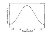
入力パルスは、波長可変光源より出力される連続光を、ZカットLN強度変調器によって変調して得られるパルスを想定する。図3に自己相関波形を示す。このパルスは、フーリエ変換限界の場合にFWHMが6.1psとなる帯域を持つパルスがアップチャープしたもので、自己相関波形をsech関数でフィッティングしてFWHMを算出すると、8.5psになるように設定している。以下では、このパルス列を入力として用いた場合のパルス圧縮結果を示す。 The input pulse is assumed to be a pulse obtained by modulating continuous light output from a wavelength tunable light source with a Z-cut LN intensity modulator. FIG. 3 shows an autocorrelation waveform. This pulse is an up-chirped pulse with a bandwidth of FWHM of 6.1 ps at the Fourier transform limit, and is set to 8.5 ps when FWHM is calculated by fitting the autocorrelation waveform with the sech function. ing. In the following, the result of pulse compression when this pulse train is used as an input will be shown.
従来型CPFは、 HNLFとSMFを交互に接続して構成される。これに対して、ZS-NZDSFを用いた本発明のCPFの効果を明らかにするため、簡単のためSMFとZS-NZDSFの非線形性と損失をそれぞれ零と仮定する。従来型および本発明のCPFを設計し、パルス圧縮結果を数値計算により検証する。図4に、CPFを構成するために用いるHNLF、SMF、ZS-NZDSFの分散値、分散スロープ値、非線形定数、そして損失を示す。ここでZS-NZDSFの分散スロープ値はすべての波長で零であり、またSMFとZS-NZDSFの非線形定数と損失を零としている。 The conventional CPF is configured by alternately connecting HNLF and SMF. On the other hand, in order to clarify the effect of the CPF of the present invention using ZS-NZDSF, it is assumed for simplicity that the nonlinearity and loss of SMF and ZS-NZDSF are zero. The conventional and the CPF of the present invention are designed, and the pulse compression result is verified by numerical calculation. FIG. 4 shows the dispersion value, dispersion slope value, nonlinear constant, and loss of HNLF, SMF, and ZS-NZDSF used to configure the CPF. Here, the dispersion slope value of ZS-NZDSF is zero at all wavelengths, and the nonlinear constant and loss of SMF and ZS-NZDSF are zero.
従来型CPFの設計と圧縮結果
従来の構成、すなわちHNLFとSMFを交互に接続したCPFの構成で、HNLFとSMFの組が六段の場合の設計と、これを用いたパルス圧縮特性の計算結果を示す。
Conventional CPF design and compression results Conventional design, that is, a CPF configuration in which HNLF and SMF are alternately connected, and a design with six pairs of HNLF and SMF, and calculation results of pulse compression characteristics using this Indicates.
図5は、中心波長λ0 = 1570nmのときに平均パワー19.5dBmでパルスを入力する際に、出力パルス幅が1.8psで最適化されるように設計した六段CPFパルス成型器の構成を示している。ただし、SBS(誘導ブリルアン散乱)の抑圧を目的として、1段目と2段目の後にアイソレータを挿入することを考え、それぞれ挿入損失0.5dBを加えている。なお、通常アイソレータの挿入損は波長依存性を持っているが、ここでは簡単のため無視した。 Figure 5 shows the configuration of a six-stage CPF pulse shaper designed to optimize the output pulse width at 1.8 ps when inputting a pulse with an average power of 19.5 dBm when the center wavelength is λ 0 = 1570 nm. ing. However, for the purpose of suppressing SBS (stimulated Brillouin scattering), we consider inserting an isolator after the first and second stages and adding an insertion loss of 0.5 dB. Note that the insertion loss of an isolator usually has wavelength dependence, but is ignored here for simplicity.
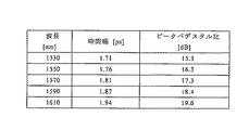
入力パワーを19.5dBmに固定し、入力パルスの中心波長λ0を1530nmから20nmおきに1610nmまで変化させたときの、六段CPF出力パルスの時間幅とピークペデスタル比の値を図6に示す。ただしピークペデスタル比は、出力パルスの自己相関波形において、sech関数でフィッティングした曲線とのずれが、比で1dBとなる点とピーク値との比で定義する。 FIG. 6 shows the time width and peak pedestal ratio of the six-stage CPF output pulse when the input power is fixed at 19.5 dBm and the center wavelength λ 0 of the input pulse is changed from 1530 nm to 1610 nm every 20 nm. However, the peak pedestal ratio is defined by the ratio between the peak value and the point where the deviation from the curve fitted by the sech function is 1 dB in the autocorrelation waveform of the output pulse.
また、出力パルスの自己相関波形を図7および図8に示す。なお点線は時間幅1.8ps相当のsechパルスを示している。
図6と図7および図8から、同じ入力パワーのもとでは、出力パルスの時間幅とピークペデスタル比が大きな波長依存性を持つことがわかる。これはSMFの分散値が、波長によって変化するためである。
The autocorrelation waveform of the output pulse is shown in FIGS. The dotted line indicates a sech pulse corresponding to a time width of 1.8 ps.
6, 7, and 8, it can be seen that the time width of the output pulse and the peak pedestal ratio have a large wavelength dependency under the same input power. This is because the dispersion value of SMF changes depending on the wavelength.
一方、非特許文献2で示されているように、各波長に対して入力パワーを調整することで、出力パルスの時間幅を所望の値に調整することができる。図5に設計を示した従来型CPFパルス成型器に対して、各波長において出力幅が約1.8psとなるように最適化した入力パワーと、そのときの出力パルスの時間幅およびピークペデスタル比を図9に示す。
また、出力パルスの自己相関波形を図10および図11に示す。なお点線は時間幅1.8ps相当のsechパルスを示している。
On the other hand, as shown in
The autocorrelation waveform of the output pulse is shown in FIGS. The dotted line indicates a sech pulse corresponding to a time width of 1.8 ps.
図9および図10と図11から、設計波長である1570nmより短い波長では、入力パワーを減少させることにより、設計した出力幅である1.8psに近い値を得ることができる。逆に1570nmより長い波長では、入力パワーを増加させることで、約1.8psの幅が得られる。ただし、ピークペデスタル比は依然として波長依存性を持っている。また動作波長を変化させる際に、約1.7dBの範囲で入力パワーを調整する必要があって、これはパルス光源の操作を複雑化するもので、光源の構成を簡略化するという観点からは好ましくない。 9, 10, and 11, at a wavelength shorter than the design wavelength of 1570 nm, a value close to the designed output width of 1.8 ps can be obtained by reducing the input power. Conversely, at wavelengths longer than 1570 nm, increasing the input power can provide a width of about 1.8 ps. However, the peak pedestal ratio is still wavelength dependent. Also, when changing the operating wavelength, it is necessary to adjust the input power within the range of about 1.7 dB, which complicates the operation of the pulsed light source and is preferable from the viewpoint of simplifying the configuration of the light source. Absent.
本発明のCPFの設計と圧縮結果
パルス圧縮特性に対するSMFの分散スロープの影響を低減するため、SMFの代わりにZS-NZDSFを用いてCPFを構成する。図5に設計を示した従来型CPFにおいて、一部のSMFのみをZS-NZDSFに置き換える方法も考えられるが、ここではHNLFとZS-NZDSFのみでCPFを構成することを考える。本発明のCPFの構成として、HNLFとZS-NZDSFの組が六段の場合の設計と、これを用いたパルス圧縮特性の計算結果を以下に示す。
CPF design and compression results of the present invention In order to reduce the influence of the SMF dispersion slope on the pulse compression characteristics, the CPF is constructed using ZS-NZDSF instead of SMF. In the conventional CPF whose design is shown in FIG. 5, it is possible to replace only a part of SMF with ZS-NZDSF. Here, however, it is considered that the CPF is composed of only HNLF and ZS-NZDSF. As a configuration of the CPF of the present invention, the design in the case where the set of HNLF and ZS-NZDSF is six stages and the calculation result of the pulse compression characteristics using this are shown below.
図12は、中心波長1570nmのときに平均パワー19.5dBmでパルスを入力する際に、出力パルス幅が1.8psで最適化されるように設計した本発明の六段CPFパルス成型器の構成を示しており、SMFの代わりにZS-NZDSFを用いたことを除いては、図5と同様の構成である。図5に示した従来型CPFの設計と比較すると、SMF長とZS-NZDSF長のみが異なっており、SMFとZS-NZDSFの分散値の比に応じて、各段のZS-NZDSFが長く設定されている。 FIG. 12 shows the configuration of the six-stage CPF pulse shaper of the present invention designed to optimize the output pulse width at 1.8 ps when inputting a pulse with an average power of 19.5 dBm at a center wavelength of 1570 nm. The configuration is the same as that of FIG. 5 except that ZS-NZDSF is used instead of SMF. Compared with the design of the conventional CPF shown in Fig. 5, only the SMF length and ZS-NZDSF length are different, and the ZS-NZDSF of each stage is set longer depending on the ratio of the dispersion values of SMF and ZS-NZDSF. Has been.
入力パワーを19.5dBmに固定し、入力パルスの中心波長λ0を1530nmから20nmおきに1610nmまで変化させたときの、六段CPF出力パルスの時間幅とピークペデスタル比の値を図13に示す。
また、出力パルスの自己相関波形を図14および図15に示す。なお点線は時間幅1.8ps相当のsechパルスを示している。
FIG. 13 shows the time width and peak pedestal ratio of the six-stage CPF output pulse when the input power is fixed at 19.5 dBm and the center wavelength λ 0 of the input pulse is changed from 1530 nm to 1610 nm every 20 nm.
The autocorrelation waveform of the output pulse is shown in FIGS. The dotted line indicates a sech pulse corresponding to a time width of 1.8 ps.
図13と図14および図15から、HNLFとZS-NZDSFを用いてCPFを構成することで、出力パルスの時間幅とピークペデスタル比の波長依存性が、従来型CPFの場合と比較して、大きく抑圧されていることがわかる。わずかな波長依存性の原因は、先に述べたとおり、ZS-NZDSFの普遍的な分散量であるβ2[ps2/km]が、波長λ[nm]によって変化するためである。 13, 14, and 15, the wavelength dependence of the time width of the output pulse and the peak pedestal ratio by configuring the CPF using HNLF and ZS-NZDSF, compared to the conventional CPF, It turns out that it is greatly suppressed. The reason for the slight wavelength dependency is that β 2 [ps 2 / km], which is the universal dispersion amount of ZS-NZDSF, varies depending on the wavelength λ [nm], as described above.
本発明のCPFを用いる場合でも、各波長に対して入力パワーを最適化することで、より設計値に近い出力パルス幅を実現することができる。
各波長において最適化した入力パワーと、そのときの出力パルスの時間幅およびピークペデスタル比を図16に示す。
また、出力パルスの自己相関波形を図17および18に示す。なお点線は時間幅1.8ps相当のsechパルスを示している。
Even when the CPF of the present invention is used, an output pulse width closer to the design value can be realized by optimizing the input power for each wavelength.
FIG. 16 shows the input power optimized at each wavelength, the time width of the output pulse at that time, and the peak pedestal ratio.
The autocorrelation waveform of the output pulse is shown in FIGS. The dotted line indicates a sech pulse corresponding to a time width of 1.8 ps.
図16の結果と、図9に示した従来型CPFを用いた場合の結果を比較すると、本発明のCPFを用いることで、入力パワーの調整幅と、ピークペデスタル比の波長依存性が大きく低減されたことがわかる。 When comparing the result of FIG. 16 with the result of using the conventional CPF shown in FIG. 9, by using the CPF of the present invention, the wavelength dependence of the input power adjustment width and the peak pedestal ratio is greatly reduced. You can see that
以上のように、HNLFとZS-NZDSFを交互に接続して構成する本発明のCPFを用いることで、HNLFとSMFからなる従来のCPFと比較して、出力パルス特性の波長依存性を低減できることが確認できた。 As described above, by using the CPF of the present invention configured by alternately connecting HNLF and ZS-NZDSF, the wavelength dependence of output pulse characteristics can be reduced compared to the conventional CPF consisting of HNLF and SMF. Was confirmed.
これまでは、本発明の効果を検証するために、すべての波長でZS-NZDSFの分散スロープを零とおき、また SMFとZS-NZDSFの非線形性と損失をそれぞれ零と仮定してきた。そこで、より現実的な条件設定を行った場合でも、本発明のCPFが効果的であることを数値シミュレーションによって示す。 So far, in order to verify the effect of the present invention, the dispersion slope of ZS-NZDSF is assumed to be zero at all wavelengths, and the nonlinearity and loss of SMF and ZS-NZDSF are assumed to be zero. Therefore, it is shown by numerical simulation that the CPF of the present invention is effective even when more realistic conditions are set.
まず、現実のZS-NZDSFの波長分散特性として、図1および2に測定結果を示したZS-NZDSFのうち、#2のファイバの値を用いる。なお分散値の波長依存性の観点からは、先に述べた|Δβ2/β20|の値から、#2のZS-NZDSFよりも#1が有利であるが、#1のファイバは分散値が小さいことから、ファイバ長が長くなり、さらに非線形効果が出やすいという問題点がある。 First, as the actual chromatic dispersion characteristic of the ZS-NZDSF, the value of the # 2 fiber is used in the ZS-NZDSF whose measurement results are shown in FIGS. From the viewpoint of wavelength dependence of dispersion value, # 1 is more advantageous than ZS-NZDSF of # 2 from the value of | Δβ 2 / β 20 | described above. Therefore, there is a problem that the fiber length becomes long and the nonlinear effect tends to occur.
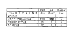
次にSMFとZS-NZDSFの非線形定数と損失として現実的な値を考慮する。HNLF、SMF、ZS-NZDSFそれぞれの1570nmにおける分散値、分散スロープ値、非線形定数、そして損失の値を図19に示す。ただし、ZS-NZDSFの分散スロープ値は、図1で1570nmにおける値を示している。以下では、各ファイバのパラメータとして、図19と図1に示した値を用いてCPFの設計、およびパルス圧縮の計算を行う。 Next, realistic values are taken into account for the nonlinear constants and losses of SMF and ZS-NZDSF. FIG. 19 shows the dispersion value, dispersion slope value, nonlinear constant, and loss value at 1570 nm of HNLF, SMF, and ZS-NZDSF. However, the dispersion slope value of ZS-NZDSF shows the value at 1570 nm in FIG. In the following, CPF design and pulse compression calculation are performed using the values shown in FIGS. 19 and 1 as the parameters of each fiber.
従来型CPFの設計と圧縮結果
まず従来構成のCPFを用いた場合の設計と、パルス圧縮計算結果を示す。
図20は、中心波長1570nmのときに平均パワー19.5dBmでパルスを入力する際に、出力パルス幅が1.8psで最適化されるように設計した六段CPFパルス成型器の構成を示している。ただし、SBSの抑圧を目的として、1段目と2段目の後にアイソレータを挿入することを考え、それぞれ挿入損失0.5dBを加えている。なお、通常アイソレータの挿入損は波長依存性を持っているが、ここでは簡単のため無視した。
Design and compression results of conventional CPF First, the design and pulse compression calculation results when using a conventional CPF are shown.
FIG. 20 shows the configuration of a six-stage CPF pulse shaper designed so that the output pulse width is optimized at 1.8 ps when a pulse is input with an average power of 19.5 dBm at a center wavelength of 1570 nm. However, for the purpose of suppressing SBS, it is considered that an isolator is inserted after the first stage and the second stage, and an insertion loss of 0.5 dB is added respectively. Note that the insertion loss of an isolator usually has wavelength dependence, but is ignored here for simplicity.
入力パワーを19.5dBmに固定し、入力パルスの中心波長λ0を1530nmから20nmおきに1610nmまで変化させたときの、六段CPF出力パルスの時間幅とピークペデスタル比の値を図21に示す。
また、出力パルスの自己相関波形を図22および図23に示す。なお点線は時間幅1.8ps相当のsechパルスを示している。
FIG. 21 shows the time width and peak pedestal ratio of the six-stage CPF output pulse when the input power is fixed at 19.5 dBm and the center wavelength λ 0 of the input pulse is changed from 1530 nm to 1610 nm every 20 nm.
Further, autocorrelation waveforms of output pulses are shown in FIGS. The dotted line indicates a sech pulse corresponding to a time width of 1.8 ps.
図21と図22および図23から、入力パワーを固定した場合に波長を変化させると、出力パルスの幅とピークペデスタル比が大きな波長依存性を持つことがわかる。これは、図6と図7および図8に示した結果と同様である。 From FIG. 21, FIG. 22, and FIG. 23, it can be seen that when the wavelength is changed when the input power is fixed, the width of the output pulse and the peak pedestal ratio have a large wavelength dependency. This is similar to the results shown in FIG. 6, FIG. 7 and FIG.
一方、図21に設計を示した従来型CPFパルス成型器に対して、各波長において出力パルスの時間幅が等しくなるように最適化した入力パワーと、そのときの出力パルスの時間幅およびピークペデスタル比を図24に示す。また、出力パルスの自己相関波形を図25および図26に示す。なお点線は時間幅1.8ps相当のsechパルスを示している。 On the other hand, with respect to the conventional CPF pulse shaper whose design is shown in FIG. 21, the input power optimized so that the time width of the output pulse is equal at each wavelength, the time width of the output pulse at that time, and the peak pedestal The ratio is shown in FIG. The autocorrelation waveform of the output pulse is shown in FIGS. The dotted line indicates a sech pulse corresponding to a time width of 1.8 ps.
このように、現実的な条件設定を行った場合でも、従来型CPFにおいて各波長に対する入力パワーを最適化することで所望のパルス幅を得ることはできる。ところがパワーの調整範囲は1.7dBにおよび、さらにピークペデスタル比は依然として波長依存性を持つ。 Thus, even when realistic conditions are set, a desired pulse width can be obtained by optimizing the input power for each wavelength in the conventional CPF. However, the power adjustment range is 1.7 dB, and the peak pedestal ratio is still wavelength dependent.
本発明のCPFの設計と圧縮結果
ZS-NZDSFのパラメータとして、図19と図1に示した値を用いる際、CPFを構成する上で慎重に考察すべき点は、ZS-NZDSFで発生する非線形効果がSMFと比較して大きいということである。そもそもZS-NZDSFはSMFよりも大きな非線形定数を持っているが、加えてZS-NZDSFの分散値はSMFの約1/3であることから、CPFを構成するためにSMFと同じ分散量を与えるために、ファイバ長をより長く設定する必要があって、結果的に非線形効果の蓄積量も増大するのである。非線形性と損失を無視した場合は、図5と図12に示したように、従来型および本発明のCPF設計の相違点が、SMF長とZS-NZDSF長のみであった。これに対して、図19と図1に示したファイバパラメータを用いてCPFを設計する場合、段数やHNLF長などが、図20に設計を示した従来型CPFとは異なる結果となる。
CPF design and compression results of the present invention
When using the values shown in Fig. 19 and Fig. 1 as parameters of ZS-NZDSF, the point that should be carefully considered in constructing CPF is that the nonlinear effect generated in ZS-NZDSF is larger than that of SMF. That is. In the first place, ZS-NZDSF has a larger nonlinear constant than SMF, but in addition, since the dispersion value of ZS-NZDSF is about 1/3 of SMF, it gives the same amount of dispersion as SMF to constitute CPF. Therefore, it is necessary to set the fiber length longer, and as a result, the amount of accumulated nonlinear effect increases. When non-linearity and loss were ignored, as shown in FIG. 5 and FIG. 12, the difference between the conventional type and the CPF design of the present invention was only the SMF length and the ZS-NZDSF length. On the other hand, when a CPF is designed using the fiber parameters shown in FIGS. 19 and 1, the number of stages, the HNLF length, and the like are different from those of the conventional CPF shown in FIG.
図27に、HNLFとZS-NZDSFの組が四段で構成される本発明のCPFパルス成型器の設計を示す。ただし、SBSの抑圧を目的として、一段目と二段目の後にアイソレータを挿入することを考え、それぞれ挿入損失0.5dBを加えている。なお、通常アイソレータの挿入損は波長依存性を持っているが、ここでは簡単のため無視した。 FIG. 27 shows the design of the CPF pulse shaper according to the present invention in which the combination of HNLF and ZS-NZDSF is composed of four stages. However, for the purpose of suppressing SBS, it is considered that an isolator is inserted after the first stage and the second stage, and an insertion loss of 0.5 dB is added to each. Note that the insertion loss of an isolator usually has wavelength dependence, but is ignored here for simplicity.
入力パワーを19.5dBmに固定し、入力パルスの中心波長λ0を1530nmから20nmおきに1610nmまで変化させたときの出力パルスの時間幅とピークペデスタル比を図28に示す。また、出力パルスの自己相関波形を図29および図30に示す。なお点線は時間幅1.8ps相当のsechパルスを示している。 FIG. 28 shows the time width and peak pedestal ratio of the output pulse when the input power is fixed at 19.5 dBm and the center wavelength λ 0 of the input pulse is changed from 1530 nm to 1610 nm every 20 nm. The autocorrelation waveform of the output pulse is shown in FIGS. The dotted line indicates a sech pulse corresponding to a time width of 1.8 ps.
図28と図29および図30から、出力特性に波長依存性が見られるものの、図21と図22および図23と比較すると、本発明のCPFを用いることで波長依存性が抑圧されていることがわかる。 Although FIG. 28, FIG. 29, and FIG. 30 show wavelength dependence in the output characteristics, the wavelength dependence is suppressed by using the CPF of the present invention as compared with FIG. 21, FIG. 22, and FIG. I understand.
一方、図27に設計を示した本発明のCPFパルス成型器に対して、各波長において出力パルスの時間幅が等しくなるように最適化した入力パワーと、そのときの出力パルスの時間幅およびピークペデスタル比を図31に示す。また、出力パルスの自己相関波形を図32および図33に示す。なお点線は時間幅1.8ps相当のsechパルスを示している。 On the other hand, with respect to the CPF pulse shaper of the present invention whose design is shown in FIG. 27, the input power optimized so that the time width of the output pulse is equal at each wavelength, the time width and peak of the output pulse at that time The pedestal ratio is shown in FIG. Further, autocorrelation waveforms of output pulses are shown in FIGS. The dotted line indicates a sech pulse corresponding to a time width of 1.8 ps.
図31の結果と、図24に示した従来型CPFを用いた場合の結果を比較すると、本発明のCPFを用いることにより、入力パワーの調整幅と、ピークペデスタル比の波長依存性が大きく低減されたことがわかる。
以上より、現実的なパラメータ設定を行った場合でも、HNLFとZS-NZDSFを交互に接続して構成する、本発明のCPFの効果を確認できた。
When the result of FIG. 31 is compared with the result of using the conventional CPF shown in FIG. 24, the use of the CPF of the present invention greatly reduces the wavelength dependence of the input power adjustment range and the peak pedestal ratio. You can see that
As described above, even when realistic parameter setting is performed, the effect of the CPF of the present invention in which HNLF and ZS-NZDSF are connected alternately can be confirmed.
図19にパラメータを示したZS-NZDSFにおいて、幅6psで40GHz繰り返しのsechパルス列が光ソリトンとして伝搬するために必要なパワーは約18.1dBmと計算される。つまり19.5dBmの入力パワーで図3に示したパルスをZS-NZDSFに入力すると、ソリトン効果によってパルスの幅が圧縮されることになる。その結果、図27に設計を示したCPFにおいて、一段目のHNLFを除去した構成でも、ZS-NZDSFのみでパルスのスペクトルを広げ、同時に時間幅を圧縮することが可能である。以下に数値シミュレーションによって得た結果を示す。 In the ZS-NZDSF whose parameters are shown in FIG. 19, the power required to propagate a sech pulse train having a width of 6 ps and a repetition rate of 40 GHz as an optical soliton is calculated to be about 18.1 dBm. That is, when the pulse shown in FIG. 3 is input to the ZS-NZDSF with an input power of 19.5 dBm, the pulse width is compressed by the soliton effect. As a result, in the CPF whose design is shown in FIG. 27, it is possible to broaden the pulse spectrum with only ZS-NZDSF and simultaneously compress the time width even with the configuration in which the first-stage HNLF is removed. The results obtained by numerical simulation are shown below.
例えば、図27に示したCPF の一段目について、HNLF長を零とし、代わりにZS-NZDSF長を1.7kmとおいた場合に、ほぼ同じ出力波形が得られる。入力パワーを19.5dBm、波長を1570nmとしたときに、図27の一段目を伝搬したパルスと、ZS-NZDSF1.7kmを伝搬したパルスの自己相関波形を重ねてプロットし、図34と図35にそれぞれ線形軸と対数軸で示す。なお点線は、時間幅3.34ps相当のsechパルスを示している。図34と図35から、図27に示したCPF の一段目について、HNLF長を零とし、代わりにZS-NZDSF長を1.7kmとおいた場合でも、一段目出力波形がほぼ同じであることがわかる。 For example, in the first stage of the CPF shown in FIG. 27, when the HNLF length is set to zero and the ZS-NZDSF length is set to 1.7 km instead, substantially the same output waveform is obtained. When the input power is 19.5 dBm and the wavelength is 1570 nm, the autocorrelation waveform of the pulse propagated through the first stage of FIG. 27 and the pulse propagated through ZS-NZDSF 1.7 km is superimposed and plotted. Each is shown with a linear axis and a logarithmic axis. The dotted line indicates a sech pulse corresponding to a time width of 3.34 ps. 34 and 35, it can be seen that the output waveform of the first stage is almost the same even when the HNLF length is zero and the ZS-NZDSF length is 1.7 km instead of the first stage of the CPF shown in FIG. .
図27に示したCPFにおいて、一段目のHNLF長を零とし、ZS-NZDSF長を1700mに変更すると、構成は図36のようになる。図36において、一段目はZS-NZDSFのみであるから、HNLFとZS-NZDSFからなるCPFの一段とは異なるが、ここでは便宜上CPFの一段と言い、図36の構成を四段CPFパルス成型器と言う。 In the CPF shown in FIG. 27, when the first stage HNLF length is set to zero and the ZS-NZDSF length is changed to 1700 m, the configuration is as shown in FIG. In FIG. 36, since the first stage is only ZS-NZDSF, it is different from one stage of CPF composed of HNLF and ZS-NZDSF, but here it is called one stage of CPF for convenience and the configuration of FIG. 36 is called a four-stage CPF pulse shaper. .
入力パワーを19.5dBmに固定し、入力パルスの中心波長λ0を1530nmから20nmおきに1610nmまで変化させたときの出力パルスの時間幅とピークペデスタル比を図37に示す。また、出力パルスの自己相関波形を図38および図39に示す。なお点線は時間幅1.8ps相当のsechパルスを示している。 FIG. 37 shows the time width and peak pedestal ratio of the output pulse when the input power is fixed at 19.5 dBm and the center wavelength λ 0 of the input pulse is changed from 1530 nm to 1610 nm every 20 nm. Further, autocorrelation waveforms of output pulses are shown in FIGS. The dotted line indicates a sech pulse corresponding to a time width of 1.8 ps.
図28と図29および図30とほぼ同じ結果が得られた。一方、図36に設計を示した本発明のCPFパルス成型器に対して、各波長において出力パルスの時間幅が等しくなるように最適化した入力パワーと、そのときの出力パルスの時間幅およびピークペデスタル比を図40に示す。また、出力パルスの自己相関波形を図41および図42に示す。なお点線は時間幅1.8ps相当のsechパルスを示している。 Almost the same results as in FIGS. 28, 29 and 30 were obtained. On the other hand, with respect to the CPF pulse shaper of the present invention whose design is shown in FIG. 36, the input power optimized so that the time width of the output pulse is equal at each wavelength, the time width and peak of the output pulse at that time The pedestal ratio is shown in FIG. Further, autocorrelation waveforms of output pulses are shown in FIGS. The dotted line indicates a sech pulse corresponding to a time width of 1.8 ps.
図31と図32および図33とほぼ同じ結果が得られた。このように、CPF一段目のHNLF長を零として、ZS-NZDSFのみの構成とすることで、出力特性を保持しながら、構成が簡略化されたCPFを実現することができる。 The same results as in FIGS. 31, 32 and 33 were obtained. Thus, by setting the HNLF length of the first stage of the CPF to zero and using only the ZS-NZDSF, it is possible to realize a CPF with a simplified configuration while maintaining output characteristics.
上記実施例では、いずれも本発明のCPFパルス成型器を用いて光パルスの電力半値幅を8.5psから1.8psに圧縮している。これに加えて、本発明のCPFパルス成型器によれば、CLバンド帯で波長可変なフェムト秒圧縮を実現することが可能となる。CLバンド帯での波長可変フェムト秒圧縮は、HNLFとSMFを組み合わせた従来のCPFでは実現不可能であった。 In any of the above-described embodiments, the power half-value width of the optical pulse is compressed from 8.5 ps to 1.8 ps using the CPF pulse shaper of the present invention. In addition, according to the CPF pulse shaper of the present invention, femtosecond compression with variable wavelength in the CL band can be realized. Tunable femtosecond compression in the CL band is not possible with conventional CPF combining HNLF and SMF.
本発明のCPFパルス成型器により波長可変フェムト秒圧縮を実現するための構成例を図43に示す。同図では、光パルス生成部110において電力半値幅約8.5psの40GHz繰り返しパルス列を生成し、本発明のCPFパルス成型器101を含むパルス成型器100が、前記パルス列を入力して電力半値幅を圧縮する構成を示している。
A configuration example for realizing wavelength variable femtosecond compression by the CPF pulse shaper of the present invention is shown in FIG. In the figure, the
本実施例のパルス成型器100は、1.8km長ZS−NZDSF 102と、低分散スロープを有するHNLFと零分散スロープのZS−NZDSFからなるCPF101とで構成されている。CPF101は、前記HNLFとZS−NZDSFとを5段組み合わせて構成されており、本実施例ではCPF101の前段にさらに1.8km長のZS−NZDSF 102を備えている。1.8km長ZS−NZDSF 102は、ソリトン効果によりパルス圧縮を行うソリトン変換器として機能するものであり、光パルス生成部110から入力した電力半値幅約8.5psのパルス列を幅約4ps(sech関数でフィッティングしたときの電力半値幅)に圧縮している。
The
1.8km長ZS−NZDSF 102で電力半値幅が約4psに圧縮されたパルス列は、アイソレータ103を経由してCPF101に入力される。ここでアイソレータ103は、CPF101におけるSBSを抑圧することを目的に、1.8km長ZS−NZDSF 102とCPF101との間に設置されている。
The pulse train whose half-power width is compressed to about 4 ps by the 1.8 km long ZS-
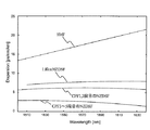
CPF101は、前記HNLFとZS−NZDSFとを交互に5段組み合わせて構成されている。CPF101に用いられるZS−NZDSF、および1.8km長のZS−NZDSF 102のそれぞれの分散値の測定結果を図44に示す。λ0 = 1570 [nm]、Δλ= 40 [nm]としたとき、図44に示したZS-NZDSFの1.8kmNZDSF, CPF1,2段目のNZDSF, およびCPF3〜5段目のNZDSFについて、それぞれβ20 = -10.14、-8.16、-3.44 [ps2/km]、Δβ2 = 1.028、0.662、0.622 [ps2/km]、|Δβ2/β20| = 0.101、0.081、0.181である。CPF101は、分散値の異なる2種類のNZDSFを用いており、1、2段目のNZDSFは、3〜5段目のNZDSFよりも高い分散値を有している。また、1.8km長ZS−NZDSF 102には、上記のCPF101に用いられる2種類のNZDSFよりもさらに高い分散値を有するNZDSFを用いている。
The
1.8km長ZS−NZDSF 102に用いられるNZDSF、およびCPF101に用いられる2種類のNZDSFは、図44に見られるとおり、いずれも分散スロープがほぼゼロとなっているのが特徴である。図44には、参考としてSMFの分散値も併せて示している。同図に示したSMF は、波長1550nmのときの分散値が16.264ps/nm/kmで、分散スロープ値が0.0586ps/nm2/kmのものである。
As shown in FIG. 44, the NZDSF used for the 1.8 km long ZS-
図44に示す分散値を有するNZDSFを用いて構成されたCPF101は、その分散値と非線形定数が図45に示すようなプロファイルを形成する。なおCPFの後段ではファイバ長が数mのオーダーであるが、分散値の小さなNZDSFを用いることで、ファイバ長に高い精度が要求されず、調整を容易にできるようにしている。CPF101の分散値と非線形定数のプロファイルをこのように形成することにより、1.8km長ZS−NZDSF 102から入力した電力半値幅約4psのパルス列を、電力半値幅100fs程度のフェムト秒オーダーのパルス列に変換することができる。
The
一方、光パルス生成部110は、TLS(Tunable Laser Source;波長可変光源)111と、40GHz正弦波電気信号発振器112と、LNM(Lithium Niobate Modulator;LN変調器)113と、EDFA(Erbium Doped Fiber Amplifier;エルビウム添加ファイバ増幅器)114と、BPF(Band Pass Filter)115と、PC(Polarization Controller;偏波コントローラ)116と、VOA(Variable Optical Attenuator;可変光減衰器)117とから構成されている。
On the other hand, the
TLS111は、連続光であるレーザー光を波長可変に出力させるものであり、前記レーザー光の位相を変調するためのCC(Coherence Control)機能を持たせている(図中ではTLS(w/CC)と表記)。該CC機能は、1.8km長 ZS−NZDSF 102でのSBSを抑圧するために備えられたものである。1.8km長 ZS−NZDSF 102を複数に分割し、その間にアイソレータを挿入することで、前記CC機能を用いないようにすることも可能である。
TLS111 outputs laser light, which is continuous light, with variable wavelength, and has a CC (Coherence Control) function to modulate the phase of the laser light (TLS (w / CC) in the figure) Notation). The CC function is provided to suppress SBS in the 1.8 km long ZS-
LNM113は、TLS111から出力されるレーザー光を40GHz正弦波電気信号発振器112から印加された40GHzの電気信号に従って強度変調することによって、繰り返し周波数が40GHzのパルス列を出力する。ここでは、パルス列の繰り返し周波数を40GHzとしたが、40GHz正弦波電気信号発振器112からLNM113に印加する電気信号の繰り返し周波数を変化させることで、パルス列の繰り返し周波数を可変とすることができる。
The
TLS111から出力されるレーザー光として、CLバンド帯の広帯域の波長のものを対象とする本実施例では、EDFA114として2段構成のものと3段構成のものの2種類を用いている。すなわち、例えば前記波長がCバンドの1530nmとLバンドの1570nmのときには2段構成とし、Lバンドの1610nmのときには3段構成としている。
In this embodiment, which targets the laser beam having a broad wavelength in the CL band as the laser light output from the
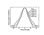
上記構成の光パルス生成部110と本発明のCPFパルス成型器101を含むパルス成型器100を用いて実現したフェムト秒圧縮の例を、実験結果にもとづいて以下に説明する。図46は、CPFパルス成型器100の入力光の波長が1530nmのときの自己相関波形とスペクトルの測定結果を示している。図46に示す入力光の電力半値幅(FWHM)は、8.56psとなっている。
An example of femtosecond compression realized by using the
図46に示す入力光を1.8km長ZS−NZDSF 102に入力して成型されたパルス波形の測定結果を図47に示す。同図より、電力半値幅8.56psの入力光が3.30psに圧縮されて1.8km長ZS−NZDSF 102から出力されることがわかる。なお、上記結果は、1.8km長ZS−NZDSF 102への入力パワー(すなわち、パルス成型器100への入力パワー)を20.0dBmとしたときの結果である。
FIG. 47 shows the measurement result of the pulse waveform formed by inputting the input light shown in FIG. 46 to the 1.8 km long ZS-
1.8km長ZS−NZDSF 102からの出力光を、さらにCPF101に入力して成型したパルスの測定結果を図48に示す。図48(a)に示す自己相関波形では、CPF101からの出力パルスの波形をガウス関数でフィッティングして電力半値幅を求めている。その結果、CPF101の出力パルスのパルス幅は、108fsに圧縮されていることがわかる。また図48(b)からは、CPF101の出力パルスのスペクトルが十分広がっていることがわかる。
FIG. 48 shows the measurement results of the pulse formed by inputting the output light from the 1.8 km long ZS-
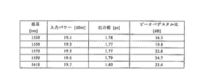
同様にして、パルス成型器100の入力光の波長が1570nmのときと1610nmのときの測定結果を、それぞれ図49〜51と図52〜54に示す。波長が1570nmのときには、パルス成型器100への入力光のパルス幅は8.69psであり、入力パワーは19.5dBmとしている。その結果、1.8km長ZS−NZDSF 102からの出力光の電力半値幅は、3.98psに圧縮され、さらにCPF101で97.1fsまで圧縮されている。
Similarly, the measurement results when the wavelength of the input light of the
また、パルス成型器100への入力光の波長が1610nmのときには、前記入力光のパルス幅は8.56psであり、入力パワーは21dBmとしている。その結果、1.8km 長ZS−NZDSF 102からの出力光の電力半値幅は、3.72psに圧縮され、さらにCPF101で104fsまで圧縮されている。
When the wavelength of the input light to the
一方、図51(b)、図54(b)に示すスペクトルからは、図48(b)と同様に、中心波長を大きく変化させてもCPF101の出力パルスのスペクトルが十分広がっていることがわかる。 On the other hand, from the spectra shown in FIG. 51 (b) and FIG. 54 (b), it can be seen that the spectrum of the output pulse of CPF101 is sufficiently wide even if the center wavelength is greatly changed, as in FIG. 48 (b). .
上記の通り、本実施例のCPFパルス成型器101を含むパルス成型器100によれば、LNM113の出力光である波長1530nm〜1610 nmのCLバンドの光パルスに対し、電力半値幅を約8.5psから100fs程度にフェムト秒圧縮することが可能となる。これは、本実施例のパルス成型器100で、ZS-NZDSFを用いてCPF101を形成させるようにしたことによるものである。なお、CPFパルス成型器101の出力光にペデスタルの発生が見られる場合には、CPF101の段数を増やして精密に設計することで、該ペデスタルを低減することができる。
As described above, according to the
分散フラット・分散減少ファイバを用いて波長可変なフェムト秒圧縮を行う従来の方法に比べて、本実施例のCPFパルス成型器101は、HNLFとZS-NZDSFとを組み合わせて実現できることから、高い生産性が得られる。また、本実施例のCPFパルス成型器101は、非線形媒体と分散媒体の両方に広帯域で分散フラットなHNLFとZS-NZDSFを用いているので、CLバンドの広帯域で波長可変なフェムト秒圧縮を実現することが可能となっている。
Compared with the conventional method of variable wavelength femtosecond compression using a dispersion flat / dispersion decreasing fiber, the
また、フェムト秒パルス光源として従来から用いられているモードロックレーザでは、パルス繰り返し周波数や発振波長が固定されていたのに対し、本発明のCPFパルス成型器では、パルス繰り返し周波数、発振波長とも可変とすることができるだけでなく、データ変調を行うことも可能となり、かつ安定した特性のパルス列を成型することができる。 In addition, the pulse repetition frequency and the oscillation wavelength are fixed in the mode-locked laser conventionally used as a femtosecond pulse light source, whereas the pulse repetition frequency and the oscillation wavelength are variable in the CPF pulse shaper of the present invention. In addition, it is possible to perform data modulation and to form a pulse train with stable characteristics.
さらに、本発明のCPFパルス成型器によれば、高次ソリトン圧縮と比較して雑音増幅を低く抑えることができ、CPFの段数を増やすことでペデスタルを低減することも可能である。 Furthermore, according to the CPF pulse shaper of the present invention, noise amplification can be suppressed lower than that of high-order soliton compression, and the pedestal can be reduced by increasing the number of stages of CPF.
以上に示したように、ZS-NZDSFを用いることで、パルス圧縮動作の波長依存性を大幅に低減できる。なお本実施例では、1530nmから1610nmまでの範囲における計算結果や実験結果を示したが、さらに短波長側(Sバンド)や、長波長側でも動作可能である。 As shown above, using ZS-NZDSF can greatly reduce the wavelength dependence of the pulse compression operation. In the present embodiment, calculation results and experimental results in the range from 1530 nm to 1610 nm are shown, but operation is possible on the shorter wavelength side (S band) and longer wavelength side.
100・・・CPFパルス成型器
101・・・CPF
102・・・1.8km長ZS-NZDSF
103・・・アイソレータ
110・・・光パルス生成部
111・・・TLS
112・・・40GHz正弦波電気信号発振器
113・・・LNM
114・・・EDFA
115・・・BPF
116・・・PC
117・・・VOA
100 ...
102 ... 1.8km long ZS-NZDSF
103 ...
112 ... 40GHz sine wave
114 ... EDFA
115 ... BPF
116 ... PC
117 ... VOA
Claims (8)
所定の波長λ0[nm]における分散値をβ20[ps2 /km]とし、所定の波長範囲λ0±Δλにおける分散値とβ20との差の絶対値の最大値をΔβ2としたとき、
波長の変化幅Δλ=40[nm]に対して|Δβ 2 /β 20 |=0.193となるシングルモードファイバ(SMF)と比較して、前記分散媒体の一部または全部が、前記所定の波長範囲λ0±Δλにおける|Δβ2 /β20|が前記SMFより小さい値を有する
ことを特徴とするCPFパルス成型器。 A CPF pulse shaper equipped with CPF (Comb-like Profiled Fiber) composed of multiple combinations of nonlinear media and dispersion media,
A dispersion value at a predetermined wavelength λ 0 [nm] is β 20 [ps 2 / km], and a maximum absolute value of a difference between the dispersion value and β 20 in a predetermined wavelength range λ 0 ± Δλ is Δβ 2 . When
Compared to a single mode fiber (SMF) in which | Δβ 2 / β 20 | = 0.193 for a wavelength change width Δλ = 40 [nm], a part or all of the dispersion medium is CPF pulse reshaping device which is characterized by having the SMF smaller value | definitive in the wavelength range λ 0 ± Δλ | Δβ 2 / β 20.
ことを特徴とする請求項1に記載のCPFパルス成型器。 2. The CPF pulse shaper according to claim 1, further comprising a pulse light source that emits an optical pulse in the predetermined wavelength range λ 0 ± Δλ and enters the CPF.
ことを特徴とする請求項1または請求項2に記載のCPFパルス成型器。 The CPF pulse according to claim 1, wherein a part or all of the dispersion medium is a non-zero dispersion-shifted fiber (ZS-NZDSF). Molder.
ことを特徴とする請求項3に記載のCPFパルス成型器。 4. The CPF pulse shaper according to claim 3, wherein a part of the dispersion medium is the non- zero dispersion shifted optical fiber and the rest is a single mode fiber (SMF). 5.
ことを特徴とする請求項1から請求項4のいずれか1項に記載のCPFパルス成型器。 The CPF pulse shaper according to any one of claims 1 to 4, wherein another dispersion medium having a predetermined length is added upstream of the CPF.
ことを特徴とする請求項5に記載のCPFパルス成型器。 Said another of the dispersing medium, the predetermined definitive wavelength range | single mode in which a = 0.193 | Δβ 2 / β 20 | change in wavelength width [Delta] [lambda] = 40 with respect to [nm] | Δβ 2 / β 20 6. The CPF pulse shaper according to claim 5, wherein the CPF pulse shaper has a value smaller than that of a fiber (SMF).
ことを特徴とする請求項5または請求項6に記載のCPFパルス成型器。 The CPF pulse shaper according to claim 5 or 6, wherein the another dispersion medium is a non-zero dispersion shifted optical fiber.
ことを特徴とする請求項1から請求項7のいずれか1項に記載のCPFパルス成型器。 The CPF pulse shaper according to any one of claims 1 to 7, wherein the predetermined wavelength range includes at least a C band and an L band.
Priority Applications (1)
| Application Number | Priority Date | Filing Date | Title |
|---|---|---|---|
| JP2006047345A JP5242014B2 (en) | 2005-09-06 | 2006-02-23 | CPF pulse shaper |
Applications Claiming Priority (3)
| Application Number | Priority Date | Filing Date | Title |
|---|---|---|---|
| JP2005257393 | 2005-09-06 | ||
| JP2005257393 | 2005-09-06 | ||
| JP2006047345A JP5242014B2 (en) | 2005-09-06 | 2006-02-23 | CPF pulse shaper |
Publications (2)
| Publication Number | Publication Date |
|---|---|
| JP2007102157A JP2007102157A (en) | 2007-04-19 |
| JP5242014B2 true JP5242014B2 (en) | 2013-07-24 |
Family
ID=38029130
Family Applications (1)
| Application Number | Title | Priority Date | Filing Date |
|---|---|---|---|
| JP2006047345A Active JP5242014B2 (en) | 2005-09-06 | 2006-02-23 | CPF pulse shaper |
Country Status (1)
| Country | Link |
|---|---|
| JP (1) | JP5242014B2 (en) |
Family Cites Families (11)
| Publication number | Priority date | Publication date | Assignee | Title |
|---|---|---|---|---|
| JPS62165608A (en) * | 1986-01-17 | 1987-07-22 | Fujitsu Ltd | Single mode optical fiber |
| JPH08146479A (en) * | 1994-11-22 | 1996-06-07 | Nippon Telegr & Teleph Corp <Ntt> | Optical wavelength conversion circuit and optical delay compensation circuit |
| JPH11223741A (en) * | 1997-12-05 | 1999-08-17 | Sumitomo Electric Ind Ltd | Distributed flat optical fiber |
| US6233387B1 (en) * | 1998-11-30 | 2001-05-15 | Corning Incorporated | Broadband pulse-reshaping optical fiber |
| JP2003241001A (en) * | 2001-12-14 | 2003-08-27 | Furukawa Electric Co Ltd:The | Dispersion compensating optical fiber, optical fiber module, and optical amplifier |
| EP2375594A1 (en) * | 2002-06-11 | 2011-10-12 | The Furukawa Electric Co., Ltd. | Pulse roller |
| JP4532061B2 (en) * | 2002-09-24 | 2010-08-25 | 古河電気工業株式会社 | Waveform shaper, optical pulse generator, and optical regeneration system |
| EP1577704A4 (en) * | 2002-11-21 | 2008-01-02 | Furukawa Electric Co Ltd | Light source in optical transmission system, waveform shaper, optical pulse train generator, and optical reproduction system |
| JP3871053B2 (en) * | 2003-05-21 | 2007-01-24 | 日本電信電話株式会社 | Dispersion flat fiber |
| JP4327126B2 (en) * | 2004-11-19 | 2009-09-09 | 独立行政法人科学技術振興機構 | Optical pulse compression device, optical pulse generator, and optical pulse compression method |
| JP4785040B2 (en) * | 2005-09-06 | 2011-10-05 | 古河電気工業株式会社 | Optical wave shaper |
-
2006
- 2006-02-23 JP JP2006047345A patent/JP5242014B2/en active Active
Also Published As
| Publication number | Publication date |
|---|---|
| JP2007102157A (en) | 2007-04-19 |
Similar Documents
| Publication | Publication Date | Title |
|---|---|---|
| US6480656B1 (en) | Method and system for generating a broadband spectral continuum, method of making the system and pulse-generating system utilizing same | |
| JP6134065B2 (en) | Fiber-type optical parametric oscillator in dissipative soliton mode | |
| JP5555686B2 (en) | All-fiber type chirped pulse amplification system | |
| JP5449648B2 (en) | An inexpensive repetitive period variable light source for high energy ultrafast lasers. | |
| JP4579829B2 (en) | Light source, waveform shaper, optical pulse train generator, and optical regeneration system in optical transmission system | |
| JP4897958B2 (en) | Optical pulse shaper design method and optical pulse shaper | |
| JP5064752B2 (en) | Optical pulse train generator | |
| EP2086068A2 (en) | Optical pulse compressor | |
| WO2013103992A2 (en) | Generating ultrashort laser pulses based on two-stage pulse processing | |
| JP2009177641A (en) | Optical signal processing apparatus, optical receiving apparatus, and optical relay apparatus | |
| EP2154566B1 (en) | Optical pulse shaper, optical pulse light source, super continuum light generator and super continuum light generating method | |
| US20090002808A1 (en) | Nonlinear Chirped Pulse Fiber Amplifier With Pulse Compression | |
| JP4558565B2 (en) | Optical waveform shaper and optical signal generator using the optical waveform shaper | |
| JP5293269B2 (en) | Optical fiber transmission system and method using optical noise suppression processing | |
| JP4676143B2 (en) | Optical pulse generation method, optical pulse compression method, optical pulse generator, and optical pulse compressor | |
| Černe et al. | Compensation of optical nonlinearities in a femtosecond laser system in a broad operation regime | |
| JP5242014B2 (en) | CPF pulse shaper | |
| Boggio et al. | Performance of a two-pump fiber optical parametric amplifier in a 10 Gb/s× 64 channel dense wavelength division multiplexing system | |
| US7813035B2 (en) | Nonlinearity and dispersion management for pulse reshaping in high energy fiber amplifier | |
| Inoue et al. | Generation of 80-nm wavelength-tunable 100-fs pulse based on comblike profiled fiber comprised of HNLF and zero dispersion-slope NZDSF | |
| JP4785040B2 (en) | Optical wave shaper | |
| Nowak et al. | Stable 200 nm TDM/WDM source based on continuum generation in 2 m of fiber | |
| JP3478985B2 (en) | Optical pulse compressor | |
| JP2007178681A (en) | Multi-wavelength light source | |
| Provino et al. | Broadband and flat parametric gain with a single low-power pump in a multi-section fiber arrangement |
Legal Events
| Date | Code | Title | Description |
|---|---|---|---|
| A621 | Written request for application examination |
Free format text: JAPANESE INTERMEDIATE CODE: A621 Effective date: 20081104 |
|
| A977 | Report on retrieval |
Free format text: JAPANESE INTERMEDIATE CODE: A971007 Effective date: 20110620 |
|
| A131 | Notification of reasons for refusal |
Free format text: JAPANESE INTERMEDIATE CODE: A131 Effective date: 20110624 |
|
| A521 | Written amendment |
Free format text: JAPANESE INTERMEDIATE CODE: A523 Effective date: 20110823 |
|
| A131 | Notification of reasons for refusal |
Free format text: JAPANESE INTERMEDIATE CODE: A131 Effective date: 20120518 |
|
| A521 | Written amendment |
Free format text: JAPANESE INTERMEDIATE CODE: A523 Effective date: 20120717 |
|
| TRDD | Decision of grant or rejection written | ||
| A01 | Written decision to grant a patent or to grant a registration (utility model) |
Free format text: JAPANESE INTERMEDIATE CODE: A01 Effective date: 20130329 |
|
| A61 | First payment of annual fees (during grant procedure) |
Free format text: JAPANESE INTERMEDIATE CODE: A61 Effective date: 20130403 |
|
| FPAY | Renewal fee payment (event date is renewal date of database) |
Free format text: PAYMENT UNTIL: 20160412 Year of fee payment: 3 |
|
| R151 | Written notification of patent or utility model registration |
Ref document number: 5242014 Country of ref document: JP Free format text: JAPANESE INTERMEDIATE CODE: R151 |
|
| FPAY | Renewal fee payment (event date is renewal date of database) |
Free format text: PAYMENT UNTIL: 20160412 Year of fee payment: 3 |
|
| S531 | Written request for registration of change of domicile |
Free format text: JAPANESE INTERMEDIATE CODE: R313531 |
|
| R350 | Written notification of registration of transfer |
Free format text: JAPANESE INTERMEDIATE CODE: R350 |