JP5241272B2 - Coordinate input device, coordinate input control method, coordinate input control program - Google Patents
Coordinate input device, coordinate input control method, coordinate input control program Download PDFInfo
- Publication number
- JP5241272B2 JP5241272B2 JP2008046894A JP2008046894A JP5241272B2 JP 5241272 B2 JP5241272 B2 JP 5241272B2 JP 2008046894 A JP2008046894 A JP 2008046894A JP 2008046894 A JP2008046894 A JP 2008046894A JP 5241272 B2 JP5241272 B2 JP 5241272B2
- Authority
- JP
- Japan
- Prior art keywords
- coordinates
- coordinate
- touch
- coordinate input
- area
- Prior art date
- Legal status (The legal status is an assumption and is not a legal conclusion. Google has not performed a legal analysis and makes no representation as to the accuracy of the status listed.)
- Expired - Fee Related
Links
Images


Landscapes
- Length Measuring Devices By Optical Means (AREA)
- Position Input By Displaying (AREA)
Description
本発明は、座標入力面に対して指示された座標を検出する座標入力装置、座標入力制御方法、座標入力制御プログラムに関する。 The present invention relates to a coordinate input device, a coordinate input control method, and a coordinate input control program that detect coordinates designated on a coordinate input surface.
近年、会議システムは、旧来のホワイトボードやOHP(Overhead projector)主体のものから電子情報を表示する大型ディスプレイを備えた電子会議システムに発達している。このような電子会議システムには、例えば、参加者が個々に持ち寄った情報を効率的に共有できるようにしたり、またネットワーク情報を表示できるようにしたりする機能が備わっている。 2. Description of the Related Art In recent years, a conference system has been developed as an electronic conference system equipped with a large display for displaying electronic information from a conventional whiteboard or an OHP (Overhead projector) main body. Such an electronic conference system has a function of, for example, enabling the participants to efficiently share information brought individually and displaying network information.
電子会議システムで用いられる大型ディスプレイには、液晶ディスプレイ、プラズマディスプレイ、更には、表面電界ディスプレイ、リアプロジェクションディスプレイ等が採用され、今後益々表示面積の大型化、高精細化が図られる傾向にある。それに伴い、表示できる情報量も増加している。例えば、PC(パーソナルコンピュータ)環境においては、一画面に多数のウィンドウを同時に開き、多数のアプリケーションを動作させる環境が一般化している。 As a large display used in the electronic conference system, a liquid crystal display, a plasma display, a surface electric field display, a rear projection display, and the like are adopted, and the display area tends to increase in size and definition in the future. Along with this, the amount of information that can be displayed is also increasing. For example, in a PC (personal computer) environment, an environment in which many windows are simultaneously opened on one screen and many applications are operated is common.
このような大型ディスプレイ等に対して用いられる入力インターフェースとしては、マウス、キーボードを始めとして、ホワイトボード感覚で使えるペンや、直感的にオブジェクトにタッチできる指によるタッチパネルインターフェースがある。入力インターフェースを用いて大画面ディスプレイに表示されたオブジェクトを操作したり、描画したり、既存のドキュメントや画像に対してアノテーションしたりする使い方が提案されており、また、それを実現するための製品が工業化されている。 As an input interface used for such a large display or the like, there are a mouse and a keyboard, a pen that can be used like a white board, and a touch panel interface by a finger that can intuitively touch an object. Proposals have been made on how to operate, draw, and annotate existing documents and images using the input interface on the large screen display. Has been industrialized.
従来、大型ディスプレイ等を利用したウィンドウやオブジェクトの操作に際して、その操作性を向上させるため種々の技術が提案されている。特許文献1には、表示された画像の中から任意の画像を選択し、当該選択された画像に応じて制御の対象となる画像を切り替える技術について言及されている。また、特許文献2には、複数のアプリケーションそれぞれが表示されるウィンドウの位置及び前後関係、入力される座標データとに基づいて、その座標データをアプリケーション、OSの何れかに振り分けて供給する技術について言及されている。また、複数の参加者がいる会議においては、複数の入力が同時に行なわれるシーンが想定されるため、特許文献3には、ある入力が発生した場合、その入力が終了するまで、他の入力を禁止する排他制御に関する技術について言及されている。
Conventionally, various techniques have been proposed to improve operability when operating windows and objects using a large display or the like. Patent Document 1 mentions a technique for selecting an arbitrary image from displayed images and switching an image to be controlled according to the selected image. Japanese Patent Application Laid-Open No. 2004-228561 discloses a technique for distributing and supplying coordinate data to either an application or an OS based on the position and context of a window in which each of a plurality of applications is displayed, and input coordinate data. It has been mentioned. In a meeting with a plurality of participants, a scene in which a plurality of inputs are performed simultaneously is assumed. Therefore, when an input occurs in
ペンや指を入力インターフェースとした座標を検出する技術としては、例えば、電磁誘導方式、電磁授受方式、抵抗膜方式、静電結合方式、超音波方式、光遮断方式、ライトペン方式が知られている。座標の検出においては、座標入力面に指示具等が接触している状態のタッチダウン座標の検出の他、座標入力面から所定距離指示具等が離れている状態のタッチアップ座標を検出する方式が知られている。一般に、タッチダウン座標のことをペンダウン状態の検出座標と呼び、タッチアップ座標のことをプロキシミティ入力、近接入力等と呼ぶ。 Known techniques for detecting coordinates using a pen or finger as an input interface include, for example, an electromagnetic induction method, an electromagnetic transfer method, a resistance film method, an electrostatic coupling method, an ultrasonic method, a light blocking method, and a light pen method. Yes. In the coordinate detection, in addition to the detection of touch-down coordinates in a state where the pointing tool is in contact with the coordinate input surface, a method of detecting touch-up coordinates in a state where the predetermined distance pointing tool is separated from the coordinate input surface It has been known. In general, touch-down coordinates are referred to as pen-down detection coordinates, and touch-up coordinates are referred to as proximity input, proximity input, and the like.
描画アプリケーションの場合には、タッチダウン座標を描画線表示、タッチアップ座標をカーソル表示のみで描画線は非表示として処理するのが一般的である。また、指で入力する、いわゆるタッチパネル方式の場合、出力される座標はタッチダウン座標のみである。このタッチダウン状態を検出する技術として、特許文献4には、座標が複数検出された場合に警告を表示する技術、特許文献5には、座標入力に右手、左手の何れを利用したかにより座標を選択する技術が開示されている。また、特許文献6には、タッチダウン座標の数等の検知により、クリック操作の切換を行なう技術について言及されている。
上述した技術では、入力インターフェースが抱える問題に対して画一的に対処しようとしているため、例えば、利用するアプリケーションによっては、かえって操作性が悪くなってしまう場合がある。アプリケーションの中には、大きなメニュー(ボタン)のみで構成され、その目的となるボタンにタッチダウンされるまでのタッチアップ状態をカーソルで表示する必要がないアプリケーション(ウィンドウ領域)がある。その一方で、メニュー(ボタン)が多岐に渡って構成され、その目的となるボタンにタッチダウンされるまでのタッチアップ状態の位置をカーソル表示する必要があるアプリケーション(ウィンドウ領域)がある。このようにアプリケーションによってメニューやボタン等の構成が大きく変わるのに、これに対して画一的に対処しようとしても、操作環境の改善にはつながらない。 In the above-described technique, since the problem of the input interface is uniformly dealt with, for example, the operability may be deteriorated depending on the application to be used. Among applications, there are applications (window areas) that are configured only with large menus (buttons) and do not need to display a touch-up state with a cursor until the target button is touched down. On the other hand, there are applications (window areas) in which menus (buttons) are configured in various ways and the cursor needs to display the position of the touch-up state until the target button is touched down. In this way, the configuration of menus, buttons, and the like varies greatly depending on the application. Even if it is attempted to deal with this uniformly, it does not lead to improvement of the operating environment.
タッチアップ座標やタッチダウン座標をカーソル表示、或いはカーソル非表示とするのは、ドライバ側でアプリケーションに対してタッチアップ座標情報の送信/非送信を制御することによって可能である。しかし、この場合、タッチアップやタッチダウンに係わる座標情報が座標入力装置側からドライバに常に送信されてしまうため、その分、通信負担が増加してしまう。 The cursor display or non-display of the touch-up coordinates or the touch-down coordinates can be performed by controlling transmission / non-transmission of the touch-up coordinate information to the application on the driver side. However, in this case, coordinate information related to touch-up and touch-down is always transmitted from the coordinate input device side to the driver, and the communication burden increases accordingly.
また、複数の異なったアプリケーション、或いは同一アプリケーションが表示画面上に同時に表示されている場合には、そのアプリケーションの表示領域によってカーソル表示を必要とする領域と、そうでない領域とが混在することになる。この場合、ドライバによりカーソル表示、カーソル非表示の制御を行なおうとしても、その領域に適したカーソル表示制御は困難であり、同一画面に多様なアプリケーションが展開された場合には、操作性が悪かった。 When a plurality of different applications or the same application is displayed on the display screen at the same time, an area that requires cursor display and a non-cursor area are mixed depending on the display area of the application. . In this case, even if the driver controls the cursor display and the cursor non-display, it is difficult to perform the cursor display control suitable for the area, and the operability is improved when various applications are deployed on the same screen. It was bad.
また、上述した通り、タッチダウン座標の状態を判断することにより、誤入力等を防ぎ、操作性の向上を図った技術は提案されているが、タッチアップ座標の状態を判断し、カーソル表示に係わる座標の制御を行う技術については提案されていない。タッチダウン座標の状態だけを判断していたのでは、目的に応じた細かなカーソル表示に係わる操作の向上は図れない。 In addition, as described above, there has been proposed a technique that prevents erroneous input and the like by improving the operability by determining the state of the touch-down coordinate, but determines the state of the touch-up coordinate and displays the cursor. There is no proposal for a technique for controlling the coordinates concerned. If only the state of the touch-down coordinate is determined, the operation related to fine cursor display according to the purpose cannot be improved.
そこで、本発明は、上記実情に鑑みてなされたものであり、指示体による座標入力に際して、その操作性を向上させるようにした座標入力装置、座標入力制御方法、座標入力制御プログラムを提供することを目的とする。 Accordingly, the present invention has been made in view of the above circumstances, and provides a coordinate input device, a coordinate input control method, and a coordinate input control program that improve the operability when inputting coordinates with a pointer. With the goal.
上記目的を達成するため、本発明の一態様は、座標入力面に対して指示された座標を検出する座標入力装置であって、前記座標入力面へ指示体が接触している状態の接触位置を示すタッチダウン座標と、前記座標入力面から所定距離内に接近した非接触状態の指示体の位置を示すタッチアップ座標とを含む座標を検出する検出手段と、前記検出手段により検出された座標の前記座標入力面における領域を識別する領域識別手段と、前記検出手段によりタッチアップ座標が検出された場合、前記領域識別手段により識別された領域に応じて該タッチアップ座標に対応する座標情報のドライバへの送信、非送信を制御する制御手段とを具備し、前記座標入力面は、同一タイミングで単数の座標入力を受け付ける第1の領域と、同一タイミングで複数の座標入力を受け付ける第2の領域とを有し、前記制御手段は、前記検出手段により検出された座標がタッチアップ座標であり、前記領域識別手段により前記第2の領域に対する入力であると識別された場合、該タッチアップ座標に対応する座標情報を前記ドライバに送信しないことを特徴とする。
In order to achieve the above object, one aspect of the present invention is a coordinate input device that detects coordinates instructed on a coordinate input surface, and a contact position in a state where an indicator is in contact with the coordinate input surface. Detecting means for detecting coordinates including touch-down coordinates indicating the position of the indicator in a non-contact state approaching within a predetermined distance from the coordinate input surface, and coordinates detected by the detecting means When the touch-up coordinates are detected by the detecting means and the area identifying means for identifying the area on the coordinate input surface, coordinate information corresponding to the touch-up coordinates according to the area identified by the area identifying means and control means for controlling transmission to the driver, the non-transmission, the coordinate input surface, a first region for accepting the coordinate input singular at the same timing, double at the same timing A second area that accepts the coordinate input, and the control means identifies that the coordinates detected by the detection means are touch-up coordinates, and that the area identification means is an input to the second area If it is, coordinate information corresponding to the touch-up coordinates is not transmitted to the driver .
また、本発明の一態様は、座標入力面に対して指示された座標を検出する座標入力装置における座標入力制御方法であって、検出手段が、前記座標入力面へ指示体が接触している状態の接触位置を示すタッチダウン座標と、前記座標入力面から所定距離内に接近した非接触状態の指示体の位置を示すタッチアップ座標とを含む座標を検出する検出工程と、領域識別手段が、前記検出工程により検出された座標の前記座標入力面における領域を識別する領域識別工程と、制御手段が、前記検出工程によりタッチアップ座標が検出された場合、前記領域識別工程により識別された領域に応じて該タッチアップ座標に対応する座標情報のドライバへの送信、非送信を制御する制御工程とを含み、前記座標入力面は、同一タイミングで単数の座標入力を受け付ける第1の領域と、同一タイミングで複数の座標入力を受け付ける第2の領域とを有し、前記制御工程においては、前記検出工程において検出された座標がタッチアップ座標であり、前記領域識別工程において前記第2の領域に対する入力であると識別された場合、該タッチアップ座標に対応する座標情報を前記ドライバに送信しないことを特徴とする。
Another aspect of the present invention is a coordinate input control method in a coordinate input device that detects coordinates instructed on a coordinate input surface, wherein the detecting means is in contact with the coordinate input surface with the indicator. A detection step of detecting coordinates including a touch-down coordinate indicating a contact position in a state and a touch-up coordinate indicating a position of an indicator in a non-contact state approaching within a predetermined distance from the coordinate input surface; A region identifying step for identifying a region on the coordinate input surface of the coordinates detected by the detecting step, and a region identified by the region identifying step when the control means detects a touch-up coordinate by the detecting step. transmitting to the driver of the coordinate information corresponding to the touch-up coordinates in accordance with, seen including a control step of controlling the non-transmission, the coordinate input surface, the singular coordinate input at the same timing A first area to be received and a second area to receive a plurality of coordinate inputs at the same timing. In the control step, the coordinates detected in the detection step are touch-up coordinates, and the region identification step When the input is identified as input to the second area, coordinate information corresponding to the touch-up coordinates is not transmitted to the driver .
また、本発明の一態様は、座標入力面に対して指示された座標を検出する座標入力装置に内蔵されたコンピュータを、前記座標入力面へ指示体が接触している状態の接触位置を示すタッチダウン座標と、前記座標入力面から所定距離内に接近した非接触状態の指示体の位置を示すタッチアップ座標とを含む座標を検出する検出手段と、前記検出手段により検出された座標の前記座標入力面における領域を識別する領域識別手段と、前記検出手段によりタッチアップ座標が検出された場合、前記領域識別手段により識別された領域に応じて該タッチアップ座標に対応する座標情報のドライバへの送信、非送信を制御する制御手段とを具備し、前記座標入力面は、同一タイミングで単数の座標入力を受け付ける第1の領域と、同一タイミングで複数の座標入力を受け付ける第2の領域とを有し、前記制御手段は、前記検出手段により検出された座標がタッチアップ座標であり、前記領域識別手段により前記第2の領域に対する入力であると識別された場合、該タッチアップ座標に対応する座標情報を前記ドライバに送信しないことを特徴とする座標入力装置として機能させる。 According to another aspect of the present invention, a computer incorporated in a coordinate input device that detects coordinates designated with respect to a coordinate input surface indicates a contact position in a state where an indicator is in contact with the coordinate input surface. a touchdown coordinate, and detecting means for detecting coordinates and a touch-up coordinates indicating the position of the indicator of the non-contact state close to the within a predetermined distance from the coordinate input surface, the coordinates detected by said detecting means When a touch-up coordinate is detected by the detection unit and a region identification unit that identifies a region on the coordinate input surface, to a driver of coordinate information corresponding to the touch-up coordinate according to the region identified by the region identification unit the transmission, and a control means for controlling the non-transmission, the coordinate input surface, a first region for accepting the coordinate input singular at the same timing, double at the same timing A second area that accepts the coordinate input, and the control means identifies that the coordinates detected by the detection means are touch-up coordinates, and that the area identification means is an input to the second area If so, the coordinate information corresponding to the touch-up coordinate is not transmitted to the driver, and the coordinate input device is made to function.
本発明によれば、本構成における座標入力制御を行なわない場合よりも、指示体による座標入力に際して、その操作性を向上させられる。 According to the present invention, it is possible to improve the operability at the time of coordinate input by the indicator, compared to the case where the coordinate input control in this configuration is not performed.
以下、本発明に係わる座標入力装置、座標入力制御方法、座標入力制御プログラムの実施形態について添付図面を参照して詳細に説明する。なお、以下実施形態においては、座標入力面へペンや指等の指示体が接触している状態の接触位置を示す座標をタッチダウン座標と言う。また、座標入力面から所定距離内に接近した非接触状態のペンや指等の指示体の位置を示す座標をタッチアップ座標と言う。 Hereinafter, embodiments of a coordinate input device, a coordinate input control method, and a coordinate input control program according to the present invention will be described in detail with reference to the accompanying drawings. In the following embodiments, coordinates indicating a contact position in a state where an indicator such as a pen or a finger is in contact with the coordinate input surface are referred to as touch-down coordinates. In addition, coordinates indicating the position of a pointer such as a pen or a finger in a non-contact state that is approached within a predetermined distance from the coordinate input surface are referred to as touch-up coordinates.
(実施形態1)
図1は、本発明の実施の一形態に係わる座標入力装置2の構成の一例を示す図であり、図2は、座標入力装置2における処理の流れを示すフローチャートである。
(Embodiment 1)
FIG. 1 is a diagram illustrating an example of a configuration of a
図1において、表示デバイス1は、液晶ディスプレイ、プラズマディスプレイ、更には、表面電界ディスプレイ、リアプロジェクションディスプレイ等の表示器と、光学方式により座標入力を検出する座標入力装置2とから構成される。
In FIG. 1, a display device 1 includes a liquid crystal display, a plasma display, a display such as a surface electric field display and a rear projection display, and a
座標入力装置2は、表示器に一体的に装着され、その表示領域の一部或いは全域を座標入力面として専用ペンや指等の指示体により入力された座標を検出する。なお、本実施形態においては光学方式により座標検出を行なう場合を例に挙げて説明するが、これ以外の方式により座標入力を検出しても勿論かまわない。表示デバイス1では、表示デバイス周辺部に設けられたセンサ部21により、検出光の状態の変化を検出し、ペン等により指示された座標を検出する。検出された座標は、演算制御部22に入力される。
The
光学方式の座標入力装置においては、指による座標入力によりタッチパネルとして使用する方式と、専用ペン3によるタッチアップ座標とタッチダウン座標の両方を検出する方式とがあるが、本実施形態では、後者の方式を前提として説明する。この後者の方式における座標検出に係わる光学関連の機構は、例えば、投光手段、再帰反射手段、受光手段、角度検出手段から構成される。投光手段による投光が再帰反射手段により座標入力有効領域の周辺部に再帰反射され、その光を受光手段により受光する。そして、座標入力有効領域の少なくとも2箇所の角部に設けられた角度検出手段が、受光手段により検出された光量分布の変化から指又はペン等により指示された方向を検出し、導出した複数の角度情報に基づき位置座標を算出する。
In an optical coordinate input device, there are a method of using as a touch panel by coordinate input by a finger and a method of detecting both touch-up coordinates and touch-down coordinates by the
ここで、図2を用いて、図1に示す座標入力装置2における処理の流れについて説明する。
Here, the flow of processing in the coordinate
専用ペン3により座標入力面にタッチ(接触)(S101)されたタッチダウン(ペンダウン)状態の検出は、専用ペン3のペン先に装着された不図示のペンスイッチによる座標入力面へのタッチ検出により行われる。タッチダウンに際しては、専用ペン3からセンサ部21にタッチダウン信号が送信される(S102)。このタッチダウン信号の送信には、例えば、光学手段(赤外線等)や無線通信手段(電磁波等)が用いられる。センサ部21に送られたタッチダウン信号は更に、演算制御部22内の座標検出部23に送られる(S103)。
The touch-down (pen-down) state in which the coordinate input surface is touched (contacted) with the dedicated pen 3 (S101) is detected by detecting the touch on the coordinate input surface with a pen switch (not shown) attached to the pen tip of the
また、センサ部21では、当該センサの検出範囲内であれば、座標入力面にタッチ(接触)されているときのみならず、離れているときにも検出を行なう(S101及びS102)。そして、その指示状態の情報がセンサ部21から演算制御部22内の座標検出部23に送られる(S103)。座標検出部23では、センサ部21からの指示状態の情報に基づいて座標を検出するとともに、指示された座標を演算により算出する(S104)。この算出された座標は、タッチアップ/タッチダウン識別部24に送られる。
Further, the
タッチアップ/タッチダウン識別部24は、座標の検出に対応してセンサ部21からタッチダウン信号が送信されてきているか調べ、当該座標がタッチアップ、タッチダウン何れによるものであるかを識別する。この結果、タッチダウン信号が確認されたならば、タッチアップ/タッチダウン識別部24は、タッチダウン座標と識別する。一方、タッチダウン信号を確認できなかった場合、専用ペン3のペン先が座標入力面にタッチしていない状態、すなわち、座標入力面から離れた状態で座標が検出されているため、タッチアップ/タッチダウン識別部24は、その座標をタッチアップ座標と識別する。タッチアップ座標は、いわゆるプロキシミティ入力、近接入力時のカーソル表示座標に対応する。
The touch-up / touch-down identifying
ここで、タッチダウン信号が確認され、タッチダウン座標と識別された場合(S105でYES)、タッチアップ/タッチダウン識別部24から座標送信制御部26にタッチダウン座標情報が送られる(S111)。この場合、座標送信制御部26は、タッチダウン座標情報をそのまま入力デバイスドライバ4に送信する(S112)。
Here, when the touchdown signal is confirmed and identified as the touchdown coordinate (YES in S105), the touchdown coordinate information is sent from the touchup /
また、タッチダウン信号が確認されず、タッチアップ座標と識別された場合(S105でNO)、タッチアップ/タッチダウン識別部24は、タッチアップ座標情報を座標領域識別部25に送信する(S106)。座標領域識別部25では、当該タッチアップ座標が表示中のどのアプリケーション領域に属するのか識別し、タッチアップ座標情報に領域識別子(例えば、アプリケーションを示す識別情報)を付与する。従来、座標入力装置2において検出(識別)されたタッチアップ座標はそのまま、ドライバ又はアプリケーションに座標情報として送信されていた。なお、座標領域識別部25には、表示デバイス1上における個々のアプリケーションの表示領域、すなわち、アプリケーションの表示領域上に占めるウィンドウ領域における座標情報がアプリケーションから入力デバイスドライバ4を介して予め送られている。表示デバイス1上における個々のアプリケーションの表示領域情報は、例えば、操作者のウィンドウ操作により位置、サイズ等が変更された場合にも、座標領域識別部25に逐次送られる。このとき、座標領域識別部25では、その最新の表示領域情報を更新し記憶する。アプリケーションの表示領域上に占めるウィンドウ領域の座標情報は一般に、そのアプリケーションのウィンドウハンドルの情報を取得することにより得られる。
If the touchdown signal is not confirmed and is identified as a touchup coordinate (NO in S105), the touchup /
ここで、アプリケーション51及びアプリケーション52は、カーソル表示形態に係わる仕様が異なる。具体的には、アプリケーション51は、タッチアップ座標をカーソル表示するが、アプリケーション52は、タッチアップ座標をカーソル非表示とする。表示デバイス1の表示領域上には、タッチアップ座標をカーソル表示する第1の領域と、タッチアップ座標を非表示とする第2の領域とがある。この第1の領域(タッチアップ座標カーソル表示領域61に対応する)は、アプリケーション51に対応する表示領域であり、第2の領域(タッチアップ座標カーソル非表示領域62に対応する)は、アプリケーション52に対応する表示領域である。
Here, the
座標領域識別部25は、領域識別子が付与されたタッチアップ座標情報を演算制御部22内の座標送信制御部26に送信する(S107)。すると、座標送信制御部26では、当該送られてきたタッチアップ座標情報とそれに付与された領域識別子とに基づきタッチアップ座標情報の送信/非送信の制御を行う。タッチアップ座標情報がタッチアップ座標カーソル表示領域61内の座標である旨を示す領域識別子であった場合には(S108でYES)、座標送信制御部26は、そのタッチアップ座標情報を入力デバイスドライバ4に送信する(S109)。また、タッチアップ座標情報がタッチアップ座標カーソル非表示領域62内の座標である旨を示す領域識別子であった場合には(S108でNO)、座標送信制御部26は、そのタッチアップ座標情報を入力デバイスドライバ4に送信(非送信)しない(S110)。座標送信制御部26では、このタッチアップ座標情報の送信、非送信に係わる制御をタッチアップ座標が検出される都度実施する。
The coordinate
入力デバイスドライバ4では、送られてきた座標情報がタッチアップ座標カーソル表示領域61に対する座標であれば、その座標情報をカーソル表示座標としてアプリケーション51に送信する。タッチアップ座標カーソル非表示領域62に対するタッチアップ座標は、座標入力装置2から入力デバイスドライバ4に送信されないので、当該領域62ではカーソル表示は行なわれない。なお、領域62に対するタッチダウン座標情報は、座標入力装置2から入力デバイスドライバ4を介してアプリケーション52に送信されるため、カーソル表示される。
In the
タッチアップ座標情報がアプリケーション51に送られると、アプリケーション51は、そのタッチアップ座標情報に基づくカーソル表示を行う。タッチダウン座標情報が送られてきた場合、アプリケーション51は、タッチアップ時のカーソル表示状態からの連続性を考慮し、カーソル表示したままボタンダウンコマンドを実行する。なお、カーソル表示せずにボタンダウンコマンドを実行するようにしてもよい。一方、タッチアップ座標カーソル非表示領域62に対する座標入力の場合、アプリケーション52は、タッチアップ座標情報を受信せず、タッチダウン座標情報のみを受信し、カーソル表示無しのタッチダウンコマンド、ボタンダウンコマンドを実行する。
When the touch-up coordinate information is sent to the
以上、上述した構成により、表示デバイス1に表示されたアプリケーション51、52に応じてタッチアップ座標をカーソル表示する場合とタッチアップ座標をカーソル非表示とする場合の制御を行うことができる。
As described above, with the above-described configuration, it is possible to perform control when the cursor is displayed with the touch-up coordinates according to the
続いて、図3を用いて、指示具の指示に係わる部分の大きさに比べて細かな操作が必要とされる領域と、そうでない領域とから構成される表示領域において上記処理を行なう場合について簡単に説明する。 Next, with reference to FIG. 3, a case where the above processing is performed in a display area composed of an area that requires a finer operation than the size of the portion related to the instruction of the pointing tool and an area that does not need to be operated. Briefly described.
ここで、前者に当たる領域には、細かな操作が必要とされるオブジェクト等から構成されるアプリケーション51が表示されており、この領域をここでは、タッチアップ座標カーソル表示領域61とする。また、後者に当たる領域には、指示具の指示に係わる部分の大きさに比べて大きなオブジェクト等から構成されるアプリケーション52が表示されており、この領域をここでは、タッチアップ座標カーソル非表示領域62とする。なお、細かな操作が必要とされるオブジェクト等とは、例えば、小さな操作オブジェクト、小さな選択メニュー、細かな描画対象オブジェクト、間隔の狭い操作オブジェクト等のことを指す。また、大きなオブジェクト等とは、大きな操作オブジェクト、大きな選択メニュー、おおまかな描画対象オブジェクト、間隔の広い操作オブジェクト等のことを指す。
Here, in the area corresponding to the former, an
図3において、操作者が、指示具の指示に関わる部分、例えば専用ペン3のペン先部分の大きさに比べて、細かな操作が必要とされるオブジェクト等が表示されたタッチアップ座標カーソル表示領域61を指示しようとしたとする。この場合、タッチダウン状態となる前から専用ペン3によるタッチアップ座標に対応したカーソル表示がなされる。そのため、操作者は、カーソル表示を確認しながら、つまり、フィードバックしながら最終的なタッチダウン操作を行うことになる。これにより、指示具の指示に関わる部分の大きさに比べて細かなオブジェクト等を操作する場合にも、位置精度良く指示を行なえる。
In FIG. 3, a touch-up coordinate cursor display in which an operator displays an object or the like that requires a fine operation compared to the size of a part related to the instruction of the pointing tool, for example, the pen tip part of the
一方、操作者が、専用ペン3のペン先部分の大きさに比べて細かな操作が必要とされるオブジェクト等が表示されたタッチアップ座標カーソル非表示領域62を指示しようとしたとする。この場合、タッチアップ状態においてはカーソル表示されない。そもそも、カーソルは、マウス操作を前提として表示される。つまり、マウスの左ボタンがクリックされるまでの過程においてその指示位置を示すことを目的としたものであり、ホワイトボードアプリケーションでは、そのような表示は必要ないと考えられることもある。紙にペンで描画する指示形態をコンセプトとするアプリケーションにおいては、カーソル表示形態自体がなじまず、また、字を書く場合には、カーソル表示が操作上邪魔になる場合さえ想定される。更に、指示具の指示に関わる部分の大きさに比べて大きなオブジェクト等を操作する場合には、誤操作が生じる可能性が少ないため、カーソル表示に対する必要性が低い。このような理由により、タッチアップ座標カーソル非表示領域62において、カーソル非表示という、そのアプリケーション領域において最適な表示形態、操作環境が実現されることになる。
On the other hand, it is assumed that the operator tries to indicate the touch-up coordinate
以上のように実施形態1によれば、表示画面上の領域(この場合、アプリケーションの表示領域)に応じてカーソル表示を自動的に切り替えることができる。これにより、同一画面に多様なアプリケーションが展開された場合であっても、操作者が直感的に分かり易く操作できるユーザ・インターフェース環境を提供できる。 As described above, according to the first embodiment, the cursor display can be automatically switched according to the area on the display screen (in this case, the display area of the application). Thereby, even when various applications are developed on the same screen, it is possible to provide a user interface environment in which an operator can operate intuitively and easily.
また、カーソル表示しない場合には、座標入力装置2から入力デバイスドライバ4に座標情報が送信されないため、座標入力装置2と入力デバイスドライバ4間の通信負担の軽減や、またドライバ、アプリケーションにおける処理負担の軽減を図れる。
Further, when the cursor is not displayed, coordinate information is not transmitted from the coordinate
(実施形態2)
次に、実施形態2について説明する。実施形態2においては、座標が検出された領域ではなく、検出された座標数に応じてカーソル表示を切り替える場合について説明する。
(Embodiment 2)
Next,
図4は、実施形態2に係わる座標入力装置2の構成の一例を示す図であり、図5は、図4に示す座標入力装置2における処理の流れを示すフローチャートである。なお、図4に示す座標入力装置2の構成は基本的に、図1と同様の構成となる。相違点としては、表示デバイス1に単一のアプリケーション53のみが表示されているところと、座標領域識別部25が取り除かれ、その替わりに座標数識別部27が設けられているところである。また、座標検出部23で、複数の座標を同時に検出できるところも異なる。
FIG. 4 is a diagram illustrating an example of the configuration of the coordinate
ここで、図5を用いて、実施形態2に係わる座標入力装置2における処理の流れについて説明する。S201〜S204までの処理は、実施形態1の図2におけるS101〜S104までの処理と同様となるため、ここではその説明については省略する。なお、図5においては、複数の座標として2つの座標が同一サンプリングタイミング(以下、同一タイミングと言う場合もある)で検出された場合について説明する。
Here, the flow of processing in the coordinate
S205において、タッチアップ/タッチダウン識別部24は、座標の検出に対応してセンサ部21からタッチダウン信号が送信されてきているか調べ、当該座標がタッチアップ、タッチダウン何れによるものであるかを識別する。ここで、タッチダウン信号との対応が確認されたタッチダウン座標が含まれていた場合には(S205でYES)、タッチアップ/タッチダウン識別部24は、タッチダウン座標情報を座標送信制御部26に送信する(S213)。そして、これを受けた座標送信制御部26がタッチダウン座標情報を入力デバイスドライバ4に送信する(S214)。なお、同一タイミングで識別されたタッチアップ座標がある場合には、そのタッチアップ座標情報も入力デバイスドライバ4に送信する。
In S205, the touch-up / touch-down identifying
また、タッチダウン座標が含まれていなかった場合には(S205でNO)、タッチアップ/タッチダウン識別部24は、タッチアップ座標情報を座標数識別部27に送信する(S206)。なお、従来、座標入力装置2において検出(識別)されたタッチアップ座標はそのまま、ドライバ又はアプリケーションに座標情報として送信されていた。
If the touchdown coordinate is not included (NO in S205), the touchup /
座標数識別部27は、受信したタッチアップ座標情報が単数であるか複数であるかを識別する。タッチアップ座標情報が単数であった場合には(S207でYES)、座標数識別部27は、そのタッチアップ座標情報に単数フラグを付与し(S208)、複数であった場合には(S207でNO)、複数フラグを付与する(S209)。座標数識別部27では、フラグを付与した後、当該タッチアップ座標情報を座標送信制御部26に送信する。
The coordinate
座標送信制御部26では、座標数識別部27から送られてきたタッチアップ座標情報に単数フラグ、複数フラグの何れが付与されているかを判断する。単数フラグの場合(S210でYES)、つまり、単数のタッチアップ座標情報であった場合には、座標送信制御部26は、このタッチアップ座標情報を入力デバイスドライバ4に送信する(S211)。一方、複数フラグの場合(S210でNO)、つまり、複数のタッチアップ座標情報であった場合には、座標送信制御部26は、タッチアップ座標情報を入力デバイスドライバ4に送信(非送信)しない(S212)。
The coordinate
以上が、実施形態2に係わる座標入力装置2における処理の流れについての説明である。なお、実施形態2においては、複数の座標を同時に検出できる座標検出方式として、例えば、光学方式を用いる。光学方式の場合、同時に入力される複数座標の識別を確実にするためペン先スイッチの信号情報が必要となるが、ペン先スイッチの信号情報のないタッチアップ座標を識別情報付きで複数検出することは技術的に困難である。つまり、現状においては、複数のタッチダウン座標は検出できるが、複数のタッチアップ座標の検出は難しい。そこで、上述したように、タッチアップ座標が複数であると識別された場合には、タッチアップ座標を入力デバイスドライバ4に非送信とするのである。
The above is the description of the processing flow in the coordinate
図6は、上述した座標入力装置2における入力座標と出力座標との関係を示す図である。
FIG. 6 is a diagram illustrating a relationship between input coordinates and output coordinates in the coordinate
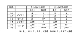
ここで、入力、出力ともにNはなし(非)を示し、UPはタッチアップ座標を示し、DOWNはタッチダウン座標を示している。なお、表番1−1〜1−6は、図5のフローチャートに対応させてある。 Here, N for input and output indicates none (not), UP indicates touch-up coordinates, and DOWN indicates touch-down coordinates. Table numbers 1-1 to 1-6 correspond to the flowchart of FIG.
この表を参照すると、上述した通り、複数のタッチアップ座標が検出された場合には、そのカーソルが非表示となることが分かる。また、タッチダウン座標とタッチアップ座標とが一つずつ混在する場合には、その両方を示す座標情報が入力デバイスドライバ4に送信されることが分かる。
Referring to this table, as described above, when a plurality of touch-up coordinates are detected, it can be seen that the cursor is not displayed. In addition, when one touchdown coordinate and one touchup coordinate are mixed, it is understood that coordinate information indicating both is transmitted to the
以上のように実施形態2によれば、同一タイミングでタッチアップ座標が複数検出された場合には、そのタッチアップ座標をドライバ(アプリケーション)側に送信しない。これにより、不確実な情報(座標の検出)により、アプリケーション側の操作性が低下するのを防ぐことができる。 As described above, according to the second embodiment, when a plurality of touch-up coordinates are detected at the same timing, the touch-up coordinates are not transmitted to the driver (application) side. Thereby, it is possible to prevent the operability on the application side from deteriorating due to uncertain information (coordinate detection).
(実施形態3)
次に、実施形態3について説明する。実施形態3においては、タッチアップ座標とタッチダウン座標の両方を含めて単数/複数を判断し、その検出された座標数に応じてカーソル表示を切り替える場合について説明する。
(Embodiment 3)
Next,
実施形態3に係わる座標入力装置2の構成は基本的に、図4と同様の構成となるため、その説明については省略する。なお、上述した実施形態においては、説明を省略したが、タッチダウンに際しては、専用ペン3各々が有する固有の識別子(以下、ペンIDと言う)と、タッチダウン信号とが同時に専用ペン3から発信され、それが座標入力装置2に入力される。
Since the configuration of the coordinate
ここで、図7、図8を用いて、実施形態3に係わる座標入力装置2における処理の流れについて説明する。なお、S301〜S304までの処理は、実施形態2の図5におけるS201〜S204までの処理と同様となるため、その説明については省略する。
Here, the flow of processing in the coordinate
S305において、タッチアップ/タッチダウン識別部24は、座標の検出に対応してセンサ部21からタッチダウン信号が送信されてきているか調べ、当該座標がタッチアップ、タッチダウン何れによるものであるかを識別する。この結果、タッチダウン信号との対応が確認されたタッチダウン座標の場合には(S305でYES)、タッチアップ/タッチダウン識別部24は、そのタッチダウン座標にタッチダウンIDを付与する。このとき、タッチダウン信号のペンID毎に指示順識別子Nも付与する(S306)。指示順識別子Nの初期値は1とされ、このルーチンを経過する都度カウントアップ(N=N+1)される。より詳細には、座標入力領域に対して最初に指示された座標の指示順識別子Nは1となり、以後、そのタッチダウンが継続されれば、その座標がサンプリングされる都度、2、3、4・・・とタッチアップされるまでカウントアップされる。
In S305, the touch-up / touch-down identifying
一方、S305においてタッチダウン信号との対応が確認されなかった座標、すなわち、タッチアップ座標の場合(S305でNO)、タッチアップ/タッチダウン識別部24は、タッチアップ座標にタッチアップIDと指示順識別子Nとを付与する(S307)。タッチアップ座標に付与する指示順識別子Nも、上述したタッチダウン座標時と同様に、初期値は1とされ、このルーチンを経過する都度カウントアップ(N=N+1)される。但し、一つ前にサンプリングされたタッチアップ座標と比較し、例えば、座標の検出位置が所定距離以内でない場合には、連続性なしとしてリセット(N=1)される。
On the other hand, in the case where the correspondence with the touch-down signal is not confirmed in S305, that is, in the case of the touch-up coordinate (NO in S305), the touch-up / touch-down identifying
タッチダウン座標、タッチアップ座標に対して指示順識別子等の付与が済むと、タッチアップ/タッチダウン識別部24は、タッチダウン座標情報、タッチアップ座標情報の何れか或いはその両方を座標数識別部27に送信する。ここで、同一タイミングで検出された座標がまだあれば(S308でNO)、再度、S305の処理に戻る。一方、同一タイミングで検出された座標が他になければ(S308でYES)、座標数識別部27において、同一タイミングにおけるタッチアップ座標、タッチダウン座標の数を識別する。
When the instruction order identifier or the like is given to the touch-down coordinates and the touch-up coordinates, the touch-up / touch-down
ここで、座標が単数であると識別された場合(S309でYES)、その単数の座標情報が座標送信制御部26に送信される(S310)。そして、これを受けた座標送信制御部26は、その単数の座標情報がタッチダウンIDを保持しているか否かを判断する。タッチダウンIDを保持していれば(S311でYES)、座標送信制御部26は、タッチダウン座標情報を入力デバイスドライバ4に送信する(S313)。一方、タッチダウンIDが保持されていない、つまり、タッチアップ座標であれば(S311でNO)、座標送信制御部26は、タッチアップ座標情報を入力デバイスドライバ4に送信する(S312)。
Here, when the coordinate is identified as singular (YES in S309), the singular coordinate information is transmitted to the coordinate transmission control unit 26 (S310). Upon receiving this, the coordinate
また、同一タイミングにおける座標の数が複数であると判断された場合には(S309でNO)、その複数の座標情報が座標送信制御部26に送信される(S314)。ここで、S315における複数座標処理を図8に示す。図8において、座標送信制御部26は、同一タイミングにおける複数の座標が、複数のタッチアップ座標であるか否かを判断する。この判断は、タッチアップIDが複数あるか否かに基づき行なわれる。この結果、複数のタッチアップIDが確認された場合には(S401でYES)、座標送信制御部26は、全ての座標情報を入力デバイスドライバ4に送信(非送信)しない(S402)。
If it is determined that there are a plurality of coordinates at the same timing (NO in S309), the plurality of coordinate information is transmitted to the coordinate transmission control unit 26 (S314). Here, the multi-coordinate processing in S315 is shown in FIG. In FIG. 8, the coordinate
一方、タッチアップIDが単数であった場合には(S401でNO)、座標送信制御部26は、全ての座標情報を入力デバイスドライバ4に送信する(S403)。なお、S401でNOとなるのは、単数のタッチアップ座標及び単数/複数のタッチダウン座標が検出された場合や、複数のタッチダウン座標が検出された場合である。
On the other hand, when the touch-up ID is singular (NO in S401), the coordinate
図9は、上述した座標入力装置2における入力座標と出力座標との関係を示す図である。ここで、入力、出力ともにNはなし(非)を示し、UPはタッチアップ座標を示し、DOWNはタッチダウン座標を示している。なお、各表番は、図7、図8のフローチャートに対応させてある。
FIG. 9 is a diagram showing a relationship between input coordinates and output coordinates in the coordinate
実施形態2で説明した図6の表と異なる点としては、まず、入力座標に対して先指示と後指示とが区別されているところである。これは、同一の座標入力領域に対して、タッチダウン、或いは、タッチアップとなった状態の時間的な後先を区別したものである。すなわち、座標入力領域に対して先に座標が入力され、それが継続されている場合には、それを先指示とし、その継続途中で入力された座標が後指示となる。 A difference from the table of FIG. 6 described in the second embodiment is that a first instruction and a rear instruction are distinguished from each other with respect to input coordinates. This distinguishes the time after the touch down or touch up state for the same coordinate input area. That is, when the coordinates are input to the coordinate input area first and are continued, this is used as the first instruction, and the coordinates input during the continuation are used as the subsequent instruction.
また、座標入力領域を示す領域の欄も、先指示と後指示とがそれぞれ設けられる。WBは、例えば、描画を主な機能とするホワイトボード領域、BMは、細かな、ボタンを伴うメニューに係わる操作領域を示す。また、表の一番右の列には、判断基準の欄を設け、入力座標に基づき出力座標へ処理する際の根拠となる判断基準が示されている。これは、操作環境、仕様を実現するための処理上のルールである。このルールの違いに関しては、後述する実施形態で説明する。 Also, the field column indicating the coordinate input area is provided with a front instruction and a rear instruction, respectively. For example, WB indicates a whiteboard area whose main function is drawing, and BM indicates an operation area related to a menu with fine buttons. In the rightmost column of the table, a determination criterion column is provided, and a determination criterion as a basis for processing to output coordinates based on input coordinates is shown. This is a processing rule for realizing the operating environment and specifications. This difference in rules will be described in an embodiment described later.
以上のように実施形態3によれば、タッチアップ座標とタッチダウン座標の両方を含めて単数/複数を判断し、座標の送信制御を行なう。この場合にも、実施形態2同様の効果が得られる。 As described above, according to the third embodiment, singular / plurality is determined including both touch-up coordinates and touch-down coordinates, and coordinate transmission control is performed. In this case, the same effect as that of the second embodiment can be obtained.
(実施形態4)
次に、実施形態4について説明する。実施形態4においては、同一タイミングで複数の座標が検出された場合に、その座標の連続性(座標検出の継続性)を考慮してカーソル表示を行なう場合について説明する。なお、実施形態4に係わる座標入力装置2における処理の一部は、実施形態3における処理と同様となるため、ここでは相違点についてのみ説明する。相違点としては、実施形態3の図8における複数座標処理にある。そのため、実施形態4では、複数座標処理についてのみ説明する。なお、実施形態4に係わる座標入力装置2の構成は基本的に、図4と同様の構成となるため、その説明については省略する。
(Embodiment 4)
Next,
図10において、この処理は、同一タイミングにおけるタッチアップ座標、タッチダウン座標の数が複数であると判断され、その複数の座標情報が座標数識別部27から座標送信制御部26に送信されると開始される。
In FIG. 10, in this process, when it is determined that there are a plurality of touch-up coordinates and touch-down coordinates at the same timing, and the plurality of pieces of coordinate information are transmitted from the coordinate
座標送信制御部26は、同一タイミングにおける複数の座標が複数のタッチアップ座標であるか否かを判断する。この判断は、タッチアップIDが複数あるか否かに基づき行なわれる。この結果、複数のタッチアップIDが確認された場合には(S501でYES)、座標送信制御部26は、全ての座標情報を入力デバイスドライバ4に送信(非送信)しない(S502)。
The coordinate
一方、タッチアップIDが単数であった場合には(S501でNO)、座標送信制御部26は、先指示の座標(指示順識別子Nのカウント数が大きい座標)のみを座標情報として入力デバイスドライバ4に送信する(S503)。すなわち、S503の処理では、(今回のサンプリングよりも)以前のサンプリング時点から検出されていた座標の座標情報を優先して入力デバイスドライバ4に送信する。
On the other hand, if the touch-up ID is singular (NO in S501), the coordinate
このようにS503において先指示の座標のみを入力デバイスドライバ4に送信するため、後指示の座標(指示順識別子Nのカウント数が小さい座標)は、入力デバイスドライバ4に送信されない。この場合の処理は、図9に示す表における表番2−7と表番2−10に対応する。表番2−7と表番2−10には、その判断基準として先着ルールが示される。例えば、表番2−7では、タッチアップが検出されるよりも先にタッチダウンが継続して検出されており、タッチダウン座標のみが入力デバイスドライバ4に送信されている。一方、表番2−10では、タッチダウンが検出されるよりも先にタッチアップが継続して検出されており、タッチアップ座標のみが入力デバイスドライバ4に送信されている。
In this way, since only the coordinates of the first instruction are transmitted to the
以上のように実施形態4によれば、座標入力領域への指示を行った順番、すなわち、タッチダウンやタッチアップの連続性(座標検出の継続性)を考慮して、入力デバイスドライバ4へ座標を送信する。これにより、例えば、タッチアップ座標を入力していた操作者が、後にきた操作者によるタッチアップ座標の入力により操作が遮断されることがなくなる。
As described above, according to the fourth embodiment, the coordinates are given to the
(実施形態5)
次に、実施形態5について説明する。実施形態5においては、座標が検出された表示画面上の領域、座標入力数の両方に応じてカーソル表示を切り替える場合について説明する。
(Embodiment 5)
Next, Embodiment 5 will be described. In the fifth embodiment, a case where the cursor display is switched according to both the area on the display screen where the coordinates are detected and the number of coordinate inputs will be described.
図11は、実施形態5に係わる座標入力装置2の構成の一例を示す図であり、図12〜図15は、図11に示す座標入力装置2における処理の流れを示すフローチャートである。なお、図11に示す座標入力装置2の構成は基本的に、図1、図4と同様の構成となる。相違点としては、アプリケーション53に対応した表示領域(ウィンドウ)内において、第1の領域(タッチアップ座標カーソル表示領域631)と第2の領域(タッチアップ座標カーソル非表示領域632)とがあるところである。タッチアップ座標カーソル表示領域631は、例えば、操作ボタン部を内在する。タッチアップ座標カーソル非表示領域632は、例えば、ホワイトボードとして専用ペン3による描画を行う領域である。なお、この領域632では、複数の専用ペン3により描画が同時に行なわれる場合もある。この場合、例えば、2つの専用ペン3による同時描画に際して、専用ペン3各々が有する固有の識別子であるIDと、タッチダウン信号とを同時に専用ペン3から発信する。座標入力装置2においては、それをセンサ部21で受信し、座標検出部23でIDを識別し、そのID信号をタッチダウン座標とともに入力デバイスドライバ4に送信する。こうすることでアプリケーション53では、入力デバイスドライバ4を経由して渡された専用ペンIDにより、専用ペン3毎に属性、例えば、色、線種、太さの異なる線で描画を行うことができる。このような構成により、座標検出部23においては、専用ペン3等による描画等が同一タイミング(厳密には、非常に近いタイミングをも含む)でなされた場合であっても、センサ部21からの複数の指示状態の情報を受け、複数座標の検出、演算を行うことができる。
FIG. 11 is a diagram illustrating an example of the configuration of the coordinate
なお、実施形態5においては、複数の座標を同時に検出できる座標検出方式として、例えば、光学方式を用いる。光学方式を用いる。光学方式の場合、同時に入力される複数座標の識別を確実にするためペン先スイッチの信号情報が必要となるが、ペン先スイッチの信号情報のないタッチアップ座標を識別情報付きで複数検出することは技術的に困難である。つまり、現状においては、複数のタッチダウン座標は検出できるが、複数のタッチアップ座標の検出は難しい。これらを考慮すると、図11に示す各表示領域は以下のようになる。 In the fifth embodiment, for example, an optical method is used as a coordinate detection method capable of simultaneously detecting a plurality of coordinates. Use optical system. In the case of the optical method, the signal information of the pen tip switch is necessary to ensure the identification of a plurality of coordinates input simultaneously, but multiple touch-up coordinates without the pen tip switch signal information are detected with the identification information. Is technically difficult. That is, at present, a plurality of touch-down coordinates can be detected, but detection of a plurality of touch-up coordinates is difficult. Considering these, each display area shown in FIG. 11 is as follows.
タッチアップ座標カーソル表示領域631は、一度に単数のみの座標入力しか受け付けない領域であり、また、タッチアップ座標をカーソル表示する領域である。タッチアップ座標カーソル非表示領域632は、複数のタッチダウンによる座標入力を受け付けるが、タッチアップ座標に係わるカーソルは非表示とする領域である。
The touch-up coordinate cursor display area 631 is an area that accepts only a single coordinate input at a time, and is an area for displaying touch-up coordinates as a cursor. The touch-up coordinate
ここで、図12〜図15を用いて、実施形態5に係わる座標入力装置2における処理の流れについて説明する。なお、S601〜S604までの処理は、実施形態1の図2におけるS101〜S104までの処理と同様となるため、ここではその説明については省略する。
Here, the flow of processing in the coordinate
S605において、タッチアップ/タッチダウン識別部24は、座標の検出に対応してセンサ部21からタッチダウン信号が送信されてきているか調べ、当該座標がタッチアップ、タッチダウン何れによるものであるかを識別する。この結果、タッチダウン信号との対応が確認されたタッチダウン座標の場合には(S605でYES)、タッチアップ/タッチダウン識別部24は、そのタッチダウン座標にタッチダウンIDを付与する。このとき、タッチダウン信号のペンID毎に指示順識別子Nも付与する。その後、タッチアップ/タッチダウン識別部24は、タッチダウンID等が付与されたタッチダウン座標情報を座標領域識別部25に送信する(S606)。
In S605, the touch-up / touch-down identifying
座標領域識別部25では、タッチダウン座標情報が表示中のアプリケーション領域内のどの領域に属するのか識別し、タッチダウン座標情報に領域識別子を付与する。すなわち、ここでは、タッチアップ座標カーソル表示領域631、タッチアップ座標カーソル非表示領域632何れで検出された座標であるかの識別を行う。ここでの処理は実質的に、一度に単数のみの座標入力しか受け付けない領域と、同時に複数の座標入力を受け付ける領域とを識別することになる。座標が検出された領域の識別が済むと、座標領域識別部25は、タッチダウン座標情報に領域を示す識別子を付与し、タッチダウン座標を座標数識別部27に送信する(S607)。
The coordinate
一方、S605においてタッチダウン信号との対応が確認されなかった座標、すなわち、タッチアップ座標の場合(S605でNO)、タッチアップ/タッチダウン識別部24は、タッチアップ座標にタッチアップIDと指示順識別子Nとを付与する。その後、タッチアップ/タッチダウン識別部24は、タッチアップID等が付与されたタッチアップ座標情報を座標領域識別部25に送信する(S608)。
On the other hand, in the case where the correspondence with the touch-down signal is not confirmed in S605, that is, in the case of the touch-up coordinate (NO in S605), the touch-up / touch-down identifying
これを受けた座標領域識別部25では、当該タッチアップ座標情報が表示中のアプリケーション領域内のどの領域に属するのか識別する。そして、その識別結果に基づく領域識別子をタッチアップ座標に付与し、そのタッチアップ座標情報を座標数識別部27に送信する(S609)。ここで、同一タイミングで検出された座標がまだあれば(S610でNO)、再度、S605の処理に戻る。一方で、同一タイミングで検出された座標が他になければ(S610でYES)、詳細は後述するが、座標送信制御処理を実施した後(S611)、この処理を終了する。
In response to this, the coordinate
続いて、図13を用いて、図12のS611における座標送信制御処理について説明する。 Next, the coordinate transmission control process in S611 of FIG. 12 will be described using FIG.
この処理が開始されると、座標数識別部27は、同一タイミングに受信した座標(タッチアップ座標、タッチダウン座標)が単数であるか複数であるかを識別する。ここで、座標が複数であると判断された場合(S701でNO)、その複数の座標情報が座標数識別部27から座標送信制御部26に送信される(S702)。その後、詳細は後述するが、複数座標送信制御処理が実施された後(S703)、この処理は終了する。
When this process is started, the coordinate
また、座標が単数であると判断された場合(S701でYES)、その単数の座標情報が座標数識別部27から座標送信制御部26に送信される(S704)。座標送信制御部26では、その単数の座標情報がタッチダウンIDを保持しているか否かを判断する。この結果、タッチダウンIDを保持していれば(S705でYES)、座標送信制御部26は、そのタッチダウン座標情報を入力デバイスドライバ4に送信する(S706)。一方、タッチダウンIDが保持されていない、つまり、タッチアップ座標情報であれば(S705でNO)、座標送信制御部26は、そのタッチアップ座標情報がタッチアップ座標カーソル非表示領域632で検出された座標であるか判断する。この結果、タッチアップ座標カーソル非表示領域632で検出された座標であれば(S707でYES)、座標送信制御部26は、そのタッチアップ座標情報を入力デバイスドライバ4に送信(非送信)しない(S708)。タッチアップ座標カーソル非表示領域632で検出された座標でなければ(S707でNO)、座標送信制御部26は、そのタッチアップ座標情報を入力デバイスドライバ4に送信する(S709)。その後、この処理は終了する。
If it is determined that the coordinates are singular (YES in S701), the singular coordinate information is transmitted from the coordinate
続いて、図14を用いて、図13のS703における複数座標送信制御処理について説明する。 Next, the multi-coordinate transmission control process in S703 of FIG. 13 will be described using FIG.
この処理が開始されると、座標送信制御部26は、複数のタッチアップ座標であるか否かを判断する。この結果、複数のタッチアップIDが確認された場合には(S801でYES)、座標送信制御部26は、全ての座標情報を入力デバイスドライバ4に送信(非送信)しない(S802)。また、タッチアップIDが単数であった場合には(S801でNO)、複数の座標の指示領域識別子が同一であるか否かを判断する。すなわち、複数の座標が同一の領域(例えば、タッチアップ座標カーソル表示領域631)で検出されたか否かを判断する。同一の領域で検出されていなければ(S803でNO)、詳細は後述するが、異領域送信制御処理を実施した後(S805)、この処理は終了する。
When this process is started, the coordinate
一方、同一の領域で検出された座標であった場合には(S803でYES)、タッチアップ座標カーソル非表示領域632で検出された座標であるか判断する。この結果、タッチアップ座標カーソル非表示領域632で検出された座標であれば(S804でYES)、座標送信制御部26は、タッチダウン座標情報のみを入力デバイスドライバ4に送信する。このとき、タッチアップ座標情報は入力デバイスドライバ4送信(非送信)されない(S806)。また、タッチアップ座標カーソル非表示領域632で検出された座標でなければ(S804でNO)、座標送信制御部26は、全ての座標情報を入力デバイスドライバ4に送信しない(S807)。これは、タッチアップ座標カーソル表示領域631では、複数の座標入力を受け付けないためである。
On the other hand, if the coordinates are detected in the same area (YES in S803), it is determined whether the coordinates are detected in the touch-up coordinate
続いて、図15を用いて、図14のS805における異領域送信制御処理について説明する。 Next, the different area transmission control process in S805 of FIG. 14 will be described with reference to FIG.
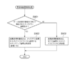
この処理が開始されると、座標送信制御部26は、複数の座標情報の中からタッチアップ座標カーソル非表示領域632で検出されたタッチダウン座標があるか否かを判断する。この結果、タッチアップ座標カーソル非表示領域632で検出されたタッチダウン座標があれば(S901でYES)、座標送信制御部26は、そのタッチダウン座標情報を入力デバイスドライバ4に送信する。このとき、タッチアップ座標は、入力デバイスドライバ4に送信(非送信)されない(S902)。これは、異なる領域に対して同時に座標入力がなされた場合には、タッチアップ座標カーソル非表示領域632への座標入力を優先させる旨の領域間の優先ルールが設定されているためである。
When this process is started, the coordinate
一方、タッチアップ座標カーソル非表示領域632で検出されたタッチダウン座標がなければ(S901でNO)、座標送信制御部26は、全ての座標情報を入力デバイスドライバ4に送信(非送信)しない(S903)。
On the other hand, if there is no touch-down coordinate detected in the touch-up coordinate cursor non-display area 632 (NO in S901), the coordinate
なお、図12〜図15に示すフローチャート(S706、S708、S709、S802、S806、S902)には、図9に示す表番がそれぞれ対応させてある。 The table numbers shown in FIG. 9 are associated with the flowcharts (S706, S708, S709, S802, S806, and S902) shown in FIGS.
以上が、実施形態5に係わる座標入力装置2における処理の流れについての説明である。このような処理を行なうことにより、例えば、図11に示すように、複数の専用ペン3で領域632に対して独立した描画が行なわれた場合、カーソル表示されない。領域632内に描画を行う際には、細かい作業を要しないというその作業の性質上、特にカーソル表示は必要とされないためである。
The above is the description of the processing flow in the coordinate
これに対して、例えば、プリントアウト操作を行おうとする場合には、領域631内のボタンを操作することになるが、その際には、間違えて隣のボタンを押さないように、細かく正確な作業が要求される。この場合、図16に示すように、操作ボタンが配置された領域631近傍に、専用ペン3を近づけると、タッチアップ座標に対応したカーソル表示がなされる。これにより、操作者は、当該表示されたカーソルを頼りにプリントアウト操作に対応したボタンを正確にタッチダウンすることができる。
On the other hand, for example, when a printout operation is to be performed, the buttons in the area 631 are operated. However, in this case, in order to avoid making a mistake and pressing the adjacent button, it is fine and accurate. Work is required. In this case, as shown in FIG. 16, when the
以上のように実施形態5によれば、正確に操作が行なえる領域631と、同時に複数の入力が行なえる領域632とを確保することができ、特に、複数入力時に不確定な座標情報を入力デバイスドライバ4側に送信することによる誤操作を抑制させられる。
As described above, according to the fifth embodiment, it is possible to secure the area 631 where the operation can be accurately performed and the
なお、実施形態5においては、領域に応じてカーソル表示を切り替える場合について説明したが、他の手段、例えば、モードによりこの切り替えを行なうようにしてもよい。 In the fifth embodiment, the case where the cursor display is switched according to the region has been described. However, this switching may be performed by other means, for example, a mode.
(実施形態6)
次に、実施形態6について説明する。実施形態6においては、同一タイミングに異なる領域で座標が検出された場合に、その座標の連続性(座標検出の継続性)を考慮してカーソル表示を行なう場合について説明する。なお、実施形態6に係わる座標入力装置2における処理の一部は、実施形態5における処理と同様となるため、ここでは相違点についてのみ説明する。相違点としては、実施形態5の図15における異領域送信制御処理にある。そのため、実施形態6では、異領域送信制御処理についてのみ説明する。なお、実施形態6に係わる座標入力装置2の構成は基本的に、図11と同様の構成となるため、その説明については省略する。
(Embodiment 6)
Next, Embodiment 6 will be described. In the sixth embodiment, a case where cursor display is performed in consideration of the continuity of coordinates (continuity of coordinate detection) when coordinates are detected in different regions at the same timing will be described. Note that part of the processing in the coordinate
図17において、この処理は、同一タイミングに異なる領域で座標が検出された場合に開始される。この処理では、まず、座標送信制御部26において、座標に付与された指示順識別子Nが参照され、先指示の座標(指示順識別子Nのカウント数が大きい座標)がタッチダウン座標であるか判断される。この結果、先指示の座標がタッチダウン座標であった場合には(S1001でYES)、座標送信制御部26は、当該タッチダウン座標情報を入力デバイスドライバ4に送信する。このとき、後指示の座標情報は、入力デバイスドライバ4に送信(非送信)されない(S1002)。
In FIG. 17, this process is started when coordinates are detected in different areas at the same timing. In this process, first, the coordinate
一方、先指示の座標がタッチアップ座標であった場合には(S1001でNO)、当該座標がタッチアップ座標カーソル非表示領域632で検出された座標であるか判断する。この結果、タッチアップ座標カーソル非表示領域632で検出された座標であれば(S1003でYES)、座標送信制御部26は、後指示のタッチダウン座標情報を入力デバイスドライバ4に送信する。このとき、先指示のタッチアップ座標は、入力デバイスドライバ4に送信(非送信)されない(S1004)。すなわち、タッチアップ座標カーソル非表示領域632では、タッチアップ座標に係わるカーソルを非表示とするため、後指示であるタッチダウン座標を優先させる。
On the other hand, if the first specified coordinate is a touch-up coordinate (NO in S1001), it is determined whether the coordinate is a coordinate detected in the touch-up coordinate
また、タッチアップ座標カーソル非表示領域632で検出された座標でなければ(S1003でNO)、座標送信制御部26は、先指示のタッチアップ座標情報を入力デバイスドライバ4に送信する。このとき、後指示の座標情報は、入力デバイスドライバ4に送信(非送信)されない(S1005)。
If the coordinates are not detected in the touch-up coordinate cursor non-display area 632 (NO in S1003), the coordinate
以上のように実施形態6によれば、同一タイミングに異なる領域で座標が検出された場合であっても、座標入力領域へ指示が行なわれた順番、すなわち座標の連続性を考慮して入力デバイスドライバ4側へ座標を送信することができる。
As described above, according to the sixth embodiment, even when coordinates are detected in different areas at the same timing, the input device is considered in consideration of the order in which instructions are given to the coordinate input area, that is, the continuity of coordinates. Coordinates can be transmitted to the
なお、実施形態6における優先ルールに限られず、例えば、後指示の座標を先指示の座標よりも絶対的に優先させるようにしてよいし、また、例えば、タッチアップ座標カーソル非表示領域632で検出された座標を絶対的に優先させる等してもよい。
Note that the priority rule is not limited to that in the sixth embodiment. For example, the post-instruction coordinate may be given priority over the pre-instruction coordinate, or may be detected in the touch-up coordinate
(実施形態7)
次に、実施形態7について説明する。上述した実施形態1〜実施形態6においては、タッチアップ座標、タッチダウン座標の状態を各々独立して比較、判断していた。しかし、実際の操作においては、タッチアップ座標状態のみでN状態(完全に指示を中止する状態)に戻る場合を除いては、タッチアップ座標状態からタッチダウン座標状態に遷移し、更に、タッチアップ座標状態へと連続的に変化する。そこで、実施形態7においては、この一連の座標入力操作に鑑み、より操作性を向上させた場合について説明する。
(Embodiment 7)
Next, Embodiment 7 will be described. In the first to sixth embodiments described above, the states of the touch-up coordinates and the touch-down coordinates are independently compared and determined. However, in actual operation, the touch-up coordinate state transitions from the touch-up coordinate state to the touch-down coordinate state except when the touch-up coordinate state alone returns to the N state (a state where the instruction is completely stopped). It changes continuously to the coordinate state. Therefore, in the seventh embodiment, a case where the operability is further improved will be described in view of this series of coordinate input operations.
図18においては、タッチダウンに際して、座標入力面に対して近づく時に検出されるタッチアップ座標をUP1、タッチダウン座標の後過程としての座標入力面から離れる時に検出されるタッチアップ座標をUP2とする。ここで、図18(a)、図18(b)に示すように、先指示と後指示とでその座標検出が逆転する逆点ポイント(逆点ポイント1〜3)が3箇所でてくる。逆点ポイントとは、先指示は、後指示よりも先に指示された一連の座標であるので、その座標が検出されなくなるまでの全ての過程において後指示よりも優先して検出されるべきであるのにそうでないところである。例えば、タッチアップ座標の検出には、未検出からタッチアップ(UP1)、及びタッチダウンからタッチアップ(UP2)の座標検出パターンがある。この変化した時点を基準として後先を比較すると、比較順位が逆転してしまう状態がある。但し、逆転ポイント2に関しては、先指示が既に未検出になっているので問題はない。
In FIG. 18, the touch-up coordinates detected when approaching the coordinate input surface during touchdown are UP1, and the touch-up coordinates detected when leaving the coordinate input surface as a subsequent process of the touchdown coordinates are UP2. . Here, as shown in FIGS. 18A and 18B, there are three reverse point points (reverse point points 1 to 3) where the coordinate detection is reversed between the first instruction and the subsequent instruction. The reverse point is a series of coordinates instructed before the post instruction, and should be detected in preference to the post instruction in all processes until the coordinates are not detected. Yes, but not so. For example, detection of touch-up coordinates includes coordinate detection patterns from non-detection to touch-up (UP1) and touch-down to touch-up (UP2). If the subsequent points are compared using the changed time as a reference, there is a state where the comparison order is reversed. However, with respect to the
また、図18(c)に示すように、UP2関連のみならず、タッチダウン座標状態においても逆転ポイントは発生する。つまり、タッチアップ座標においては先指示と判断されても、後指示の方がタッチダウンへ早いタイミングで移った場合、このような逆転現象が起きる。 Further, as shown in FIG. 18C, the reverse point occurs not only in the UP2 but also in the touchdown coordinate state. In other words, even if it is determined that the touch-up coordinate is the first instruction, such a reverse phenomenon occurs when the latter instruction moves to the touch-down at an earlier timing.
このような事態は、座標検出に際して、前後のタッチアップ座標状態とタッチダウン座標状態とを時系列に関連付けせずに検出した場合に生じる。本来、逆転ポイント1及び3では、先指示の座標が未検出とならず連続している限りは、後指示よりも常に優先してその座標情報が入力デバイスドライバ4側に送信されるべきである。
Such a situation occurs when the front and rear touch-up coordinate states and the touch-down coordinate states are detected without being associated in time series during coordinate detection. Originally, at the reverse rotation points 1 and 3, as long as the coordinates of the previous instruction are not detected and are continuous, the coordinate information should always be transmitted to the
これを実現するために、実施形態7では、連続性があると判断された座標に関しては、タッチアップ座標とタッチダウン座標の遷移が発生しても、同一の連続座標として検出する。つまり、実施形態7では、UP1〜ダウン〜UP2に到るすべての座標状態において、後指示に対して先指示であるとの識別を連続的に保持させ、逆点状態を解消させる。 In order to realize this, in the seventh embodiment, coordinates determined to have continuity are detected as the same continuous coordinates even if a transition between touch-up coordinates and touch-down coordinates occurs. That is, in the seventh embodiment, in all the coordinate states from UP1 to Down to UP2, the identification that the previous instruction is the previous instruction is continuously held, and the reverse state is eliminated.
ここで、図19に示すフローチャートを用いて、座標の連続性(座標検出の継続性)を考慮した場合の処理の流れについて説明する。なお、図19では、実施形態3における図7の処理と相違する点についてのみ説明する。 Here, the flow of processing when the continuity of coordinates (continuity of coordinate detection) is considered will be described using the flowchart shown in FIG. In FIG. 19, only differences from the processing of FIG. 7 in the third embodiment will be described.
S1105において、タッチアップ/タッチダウン識別部24は、座標の検出に対応してセンサ部21からタッチダウン信号が送信されてきているか調べ、当該座標がタッチアップ、タッチダウン何れによるものであるかを識別する。この結果、タッチダウン信号との対応が確認されたタッチダウン座標の場合には(S1105でYES)、タッチアップ/タッチダウン識別部24は、そのタッチダウン座標にタッチダウンIDを付与する。このとき、タッチダウン信号のペンID毎に指示順識別子Nも付与する(S1106)。このとき、タッチアップ/タッチダウン識別部24は、指示順識別子、座標情報、タッチダウンIDを、例えば、RAM(Random Access Memory)等の記憶手段に記憶させる。
In step S1105, the touch-up / touch-down identifying
その後、タッチアップ/タッチダウン識別部24は、今回のタッチダウン状態がタッチアップからタッチダウンへの状態変化、つまり、タッチアップ座標からの遷移によりタッチダウンになったか判断する。この判断は、上述した記憶手段に保持された前回の指示順識別子N、タッチダウンID、タッチアップIDを比較して行う。ここで、前回もタッチダウンIDであった場合には(S1107でNO)、タッチダウン状態の維持であるため、指示順識別子Nはそのままの状態となり、タッチダウン座標情報が座標数識別部27に送信される(S1109)。
Thereafter, the touch-up / touch-down identifying
一方、S1107において、前回はタッチアップIDを保持していたことが確認されれば、タッチアップからタッチダウンへの状態変化が起こっていることになる。この場合には、更に、記憶手段に記憶された前回の座標情報と今回の座標情報とを比較し座標の連続性を判断する。例えば、前回の座標との差分(距離)が所定以内の場合には、連続性有りと判断する。 On the other hand, if it is confirmed in S1107 that the previous touch-up ID was held, a state change from touch-up to touch-down has occurred. In this case, the previous coordinate information stored in the storage means is compared with the current coordinate information to determine the continuity of the coordinates. For example, if the difference (distance) from the previous coordinate is within a predetermined range, it is determined that there is continuity.
連続性があると判断されれば(S1107でYES)、それ以前のタッチアップ座標の指示順識別子Nの値を継承した上で、カウントアップを行う(S1108)。つまり、タッチアップからタッチダウンへ状態変化した場合には、例えば、それまでのタッチアップ座標の指示順識別子Nがカウント100である場合には、N=1ではなく、N=100+1=101となる。その後、タッチダウン座標情報が、タッチアップ/タッチダウン識別部24から座標数識別部27に送信される(S1109)。
If it is determined that there is continuity (YES in S1107), the count-up is performed after inheriting the value of the instruction order identifier N of the previous touch-up coordinates (S1108). That is, when the state changes from touch-up to touch-down, for example, when the instruction order identifier N of the touch-up coordinates so far is 100, N is not equal to 1, but N = 100 + 1 = 101. . Thereafter, the touchdown coordinate information is transmitted from the touchup /
また、S1105において、タッチダウン信号との対応が確認されなかった座標、すなわち、タッチアップ座標の場合(S1105でNO)、タッチアップ/タッチダウン識別部24は、そのタッチアップ座標に対して上述した処理を行なう。この処理は基本的に、タッチダウン座標におけるS1106〜S1109の処理と同様であるため、その説明は省略する。タッチダウンをタッチアップ、タッチアップからタッチダウンへの状態変化をタッチダウンからタッチアップへの状態変化、に置き換えて処理してやればよい。
Also, in S1105, in the case where the correspondence with the touchdown signal is not confirmed, that is, in the case of the touchup coordinate (NO in S1105), the touchup /
以上のように実施形態7によれば、タッチアップからタッチダウン、タッチダウンからタッチアップへの状態変化が起こった場合にも、座標の継続性を判断してカーソル表示の制御が行なえるため、上述したような逆転ポイントが生じない。座標入力を先に行なった操作者は、その操作を継続している限り、後から操作を開始した操作者の影響を受けずに済む。 As described above, according to the seventh embodiment, even when a state change occurs from touch-up to touch-down and from touch-down to touch-up, the cursor display can be controlled by determining the continuity of coordinates. The reverse point as described above does not occur. As long as the operator who performed the coordinate input first continues the operation, it is not affected by the operator who started the operation later.
なお、上記説明では、実施形態3の改良として説明したが、これに限られず、実施形態7に係わる座標の連続性を考慮した処理は、その他実施形態で説明した処理に対しても適用できる。 In the above description, the improvement of the third embodiment has been described. However, the present invention is not limited to this, and the processing considering the continuity of coordinates according to the seventh embodiment can be applied to the processing described in the other embodiments.
(実施形態8)
次に、実施形態8について説明する。上述した実施形態1〜実施形態6においては、複数のタッチアップ座標が検出された場合には、該当する複数のタッチアップ座標を入力デバイスドライバ4に対して非送信とする処理を行っていた。しかし、所定の優先ルールを定めた場合には、一部のルールにおいて、その最終過程に到るまでの途中過程でタッチダウンのカーソル表示が途切れる場合が発生する。例えば、図9に示す表における、表番2−10、2−12、2−16、2−17で示されるケースで発生する。
(Embodiment 8)
Next,
つまり、先指示のタッチアップ座標がその状態を保持した状態で後指示がタッチダウンからタッチアップへと状態変化した場合、途中で一旦、複数のタッチアップ座標状態と判断されてしまう。その瞬間に、先指示のタッチアップ座標も入力デバイスドライバ4に対して非送信となり、カーソル非表示となってしまう。
In other words, when the post-instruction changes state from touchdown to touchup while the previous instruction touchup coordinate is kept in that state, it is temporarily determined that there are a plurality of touchup coordinate states on the way. At that moment, the touch-up coordinates of the previous instruction are also not transmitted to the
そこで、実施形態8においては、実施形態3の図7におけるS315の複数座標処理を例に挙げてこの課題を解決する方法について説明する。なお、ここでは、上述した実施形態8における図19で説明したS1105〜S1113の処理により、指示順識別子には、座標の連続性(座標検出の継続性)を考慮した指示順識別子が与えられているものとする。 Therefore, in the eighth embodiment, a method for solving this problem will be described by taking the multi-coordinate process of S315 in FIG. 7 of the third embodiment as an example. Here, by the processing of S1105 to S1113 described in FIG. 19 in the above-described eighth embodiment, the instruction order identifier is given to the instruction order identifier in consideration of coordinate continuity (coordinate detection continuity). It shall be.
図20において、この処理は、同一タイミングにおけるタッチアップ座標、タッチダウン座標の数が複数であると判断され、その複数の座標情報が座標数識別部27から座標送信制御部26に送信されると開始される。
In FIG. 20, this process is performed when it is determined that there are a plurality of touch-up coordinates and touch-down coordinates at the same timing, and the plurality of pieces of coordinate information are transmitted from the coordinate
座標送信制御部26は、同一タイミングにおける複数の座標が複数のタッチアップ座標であるか否かを判断する。この判断は、タッチアップIDが複数あるか否かに基づき行なわれる。この結果、タッチアップIDが単数であった場合には(S1201でNO)、座標送信制御部26は、全ての座標情報を入力デバイスドライバ4に送信する(S1203)。なお、この処理は、上述した実施形態3における図8のS403と同様の処理となる。
The coordinate
一方で、複数のタッチアップIDが確認された場合には(S1201でYES)、座標送信制御部26は、複数のタッチアップ座標の指示順識別子を比較する。ここで、例えば、複数のタッチアップ座標各々に付与された指示順識別子をN1、N2とすると、指示順識別子Nの値が大きい方のタッチアップ座標情報を入力デバイスドライバ4に送信する(S1202)。
On the other hand, when a plurality of touch-up IDs are confirmed (YES in S1201), the coordinate
例えば、N1>N2の場合、N1の指示順識別子のタッチアップ座標情報を入力デバイスドライバ4に送信する。一方、N2の指示順識別子のタッチアップ座標情報は入力デバイスドライバ4に送信(非送信)しない。NIが付与される座標は、例えば、上述した実施形態7における図19で説明したS1105〜S1113の処理により、連続性を考慮した指示順識別子が付与されたタッチアップ座標である。また、N2が付与される座標は、初めて指示された座標である、すなわち、今回の初めてタッチアップ座標となった座標である。このように、N1やN2が付与されたタッチアップ座標は、上述した座標の継続性の判断により明確に識別できる。
For example, when N1> N2, the touch-up coordinate information of the instruction order identifier of N1 is transmitted to the
以上のように実施形態8によれば、先指示のタッチアップ座標は、UP1、UP2何れの場合であっても、後指示の座標の影響を受けることなく、入力デバイスドライバ4側に送信される。
As described above, according to the eighth embodiment, the touch-up coordinate of the previous instruction is transmitted to the
以上が本発明の代表的な実施形態の一例であるが、本発明は、上記及び図面に示す実施形態に限定することなく、その要旨を変更しない範囲内で適宜変形して実施できるものである。 The above is an example of a typical embodiment of the present invention, but the present invention is not limited to the embodiment described above and shown in the drawings, and can be appropriately modified and implemented without departing from the scope of the present invention. .
例えば、上述した実施形態においては、光学方式により座標を検出する場合について説明するが、同様の検出機能、性能を有するものならばよく、他の方式により座標検出を行なうようにしてもよい。 For example, in the above-described embodiment, a case where coordinates are detected by an optical method will be described. However, any coordinate system having a similar detection function and performance may be used, and coordinate detection may be performed by other methods.
また、上述した実施形態においては、表示器と、座標入力を検出する座標入力装置とが一体となっている場合について説明したが、それぞれが別体で構成されていても表示領域と座標入力領域が対応していれば、上記説明した実施形態における処理を実施できる。 In the above-described embodiment, the case where the display and the coordinate input device that detects the coordinate input are integrated has been described. However, the display area and the coordinate input area may be configured separately. Can cope with the processing in the above-described embodiment.
また、上述した実施形態において説明したタッチアップ座標カーソル表示領域(61、631)では、正確な操作を行うのに十分な領域が操作ボタン等の操作対象オブジェクトの周囲に確保されているのが望ましい。操作対象オブジェクト近傍にタッチアップ座標カーソル非表示領域(62、632)があると、操作対象オブジェクトに極めて近い位置でなければカーソルが表示されないことになり操作に不都合となるためである。 Moreover, in the touch-up coordinate cursor display area (61, 631) described in the above-described embodiment, it is desirable that a sufficient area for performing an accurate operation is secured around the operation target object such as the operation button. . If there is a touch-up coordinate cursor non-display area (62, 632) in the vicinity of the operation target object, the cursor is not displayed unless the position is very close to the operation target object, which is inconvenient for the operation.
また、上述した実施形態において説明したタッチアップ座標カーソル表示領域(61、631)内の操作対象オブジェクトをより正確に操作するために、実際のタッチアップ座標カーソル表示領域631の範囲よりも一定範囲その領域を広げるようにしてもよい。更に、タッチアップ座標カーソル表示領域(61、631)内への操作に際して、当該領域外に一度出た場合であっても、一定時間内或いはタッチアップ座標カーソル表示領域(61、631)から一定範囲内であれば、カーソルを表示状態のまま維持させてもよい。 Further, in order to more accurately operate the operation target object in the touch-up coordinate cursor display area (61, 631) described in the above-described embodiment, a certain range of the range of the actual touch-up coordinate cursor display area 631 The area may be expanded. Further, when an operation is performed within the touch-up coordinate cursor display area (61, 631), even if the user has once moved out of the area, a predetermined range or a certain range from the touch-up coordinate cursor display area (61, 631). If it is within, the cursor may be kept displayed.
なお、本発明は、例えば、システム、装置、方法、プログラム若しくは記録媒体等としての実施態様を採ることもできる。具体的には、複数の機器から構成されるシステムに適用してもよいし、また、一つの機器からなる装置に適用してもよい。 It should be noted that the present invention can take the form of, for example, a system, apparatus, method, program, or recording medium. Specifically, the present invention may be applied to a system composed of a plurality of devices, or may be applied to an apparatus composed of a single device.
また、本発明は、ソフトウェアのプログラムをシステム或いは装置に直接或いは遠隔から供給し、そのシステム或いは装置に内蔵されたコンピュータが該供給されたプログラムコードを読み出して実行することにより実施形態の機能が達成される場合をも含む。 Further, the present invention achieves the functions of the embodiments by supplying a software program directly or remotely to a system or apparatus, and reading and executing the supplied program code by a computer incorporated in the system or apparatus. This includes cases where
したがって、本発明の機能処理をコンピュータで実現するために、該コンピュータにインストールされるプログラムコード自体も本発明を実現するものである。つまり、本発明は、本発明の機能処理を実現するためのコンピュータプログラム(例えば、座標入力制御プログラム)自体も含まれる。その場合、プログラムの機能を有していれば、オブジェクトコード、インタプリタにより実行されるプログラム、OS(Operating System)に供給するスクリプトデータ等の形態であってもよい。 Accordingly, since the functions of the present invention are implemented by computer, the program code installed in the computer also implements the present invention. That is, the present invention includes a computer program (for example, a coordinate input control program) itself for realizing the functional processing of the present invention. In that case, as long as it has the function of a program, it may be in the form of object code, a program executed by an interpreter, script data supplied to an OS (Operating System), or the like.
コンピュータプログラムを供給するためのコンピュータ読み取り可能な記録媒体としては以下が挙げられる。例えば、フロッピー(登録商標)ディスク、ハードディスク、光ディスク、光磁気ディスク、MO、CD−ROM、CD−R、CD−RW、磁気テープ、不揮発性のメモリカード、ROM、DVD(DVD−ROM,DVD−R)などである。 Examples of the computer-readable recording medium for supplying the computer program include the following. For example, floppy (registered trademark) disk, hard disk, optical disk, magneto-optical disk, MO, CD-ROM, CD-R, CD-RW, magnetic tape, nonvolatile memory card, ROM, DVD (DVD-ROM, DVD- R).
その他、プログラムの供給方法としては、クライアントコンピュータのブラウザを用いてインターネットのホームページに接続し、該ホームページから本発明のコンピュータプログラムをハードディスク等の記録媒体にダウンロードすることが挙げられる。この場合、ダウンロードされるプログラムは、圧縮され自動インストール機能を含むファイルであってもよい。また、本発明のプログラムを構成するプログラムコードを複数のファイルに分割し、それぞれのファイルを異なるホームページからダウンロードすることによっても実現可能である。つまり、本発明の機能処理をコンピュータで実現するためのプログラムファイルを複数のユーザに対してダウンロードさせるWWWサーバも、本発明に含まれるものである。 As another program supply method, a client computer browser is used to connect to a homepage on the Internet, and the computer program of the present invention is downloaded from the homepage to a recording medium such as a hard disk. In this case, the downloaded program may be a compressed file including an automatic installation function. It can also be realized by dividing the program code constituting the program of the present invention into a plurality of files and downloading each file from a different homepage. That is, a WWW server that allows a plurality of users to download a program file for realizing the functional processing of the present invention on a computer is also included in the present invention.
また、本発明のプログラムを暗号化してCD−ROM等の記録媒体に格納してユーザに配布するという形態をとることもできる。この場合、所定の条件をクリアしたユーザに、インターネットを介してホームページから暗号を解く鍵情報をダウンロードさせ、その鍵情報を使用して暗号化されたプログラムを実行し、プログラムをコンピュータにインストールさせるようにもできる。 Further, the program of the present invention may be encrypted, stored in a recording medium such as a CD-ROM, and distributed to users. In this case, a user who has cleared a predetermined condition is allowed to download key information for decryption from a homepage via the Internet, execute an encrypted program using the key information, and install the program on the computer. You can also.
また、コンピュータが、読み出したプログラムを実行することによって、前述した実施形態の機能が実現される他、そのプログラムの指示に基づき、コンピュータ上で稼動しているOSなどとの協働で実施形態の機能が実現されてもよい。この場合、OSなどが、実際の処理の一部又は全部を行ない、その処理によって前述した実施形態の機能が実現される。 In addition to the functions of the above-described embodiment being realized by the computer executing the read program, the embodiment of the embodiment is implemented in cooperation with an OS or the like running on the computer based on an instruction of the program. A function may be realized. In this case, the OS or the like performs part or all of the actual processing, and the functions of the above-described embodiments are realized by the processing.
更に、記録媒体から読み出されたプログラムが、コンピュータに挿入された機能拡張ボードやコンピュータに接続された機能拡張ユニットに備わるメモリに書き込まれて前述の実施形態の機能の一部或いは全てが実現されてもよい。この場合、機能拡張ボードや機能拡張ユニットにプログラムが書き込まれた後、そのプログラムの指示に基づき、その機能拡張ボードや機能拡張ユニットに備わるCPU(Central Processing Unit)などが実際の処理の一部又は全部を行なう。 Furthermore, the program read from the recording medium is written in a memory provided in a function expansion board inserted into the computer or a function expansion unit connected to the computer, so that part or all of the functions of the above-described embodiments are realized. May be. In this case, after the program is written to the function expansion board or function expansion unit, the CPU (Central Processing Unit) or the like provided in the function expansion board or function expansion unit is a part of the actual processing or based on the instructions of the program. Do everything.
1 表示デバイス
2 座標入力装置
3 専用ペン
4 入力デバイスドライバ
21 センサ部
22 演算制御部
23 座標検出部
24 タッチアップ/タッチダウン識別部
25 座標領域識別部
26 座標送信制御部
27 座標数識別部
51、52、53 アプリケーション
DESCRIPTION OF SYMBOLS 1
Claims (13)
前記座標入力面へ指示体が接触している状態の接触位置を示すタッチダウン座標と、前記座標入力面から所定距離内に接近した非接触状態の指示体の位置を示すタッチアップ座標とを含む座標を検出する検出手段と、
前記検出手段により検出された座標の前記座標入力面における領域を識別する領域識別手段と、
前記検出手段によりタッチアップ座標が検出された場合、前記領域識別手段により識別された領域に応じて該タッチアップ座標に対応する座標情報のドライバへの送信、非送信を制御する制御手段と
を具備し、
前記座標入力面は、
同一タイミングで単数の座標入力を受け付ける第1の領域と、
同一タイミングで複数の座標入力を受け付ける第2の領域と
を有し、
前記制御手段は、
前記検出手段により検出された座標がタッチアップ座標であり、前記領域識別手段により前記第2の領域に対する入力であると識別された場合、該タッチアップ座標に対応する座標情報を前記ドライバに送信しない
ことを特徴とする座標入力装置。 A coordinate input device that detects coordinates designated with respect to a coordinate input surface,
Touch-down coordinates indicating a contact position in a state where the indicator is in contact with the coordinate input surface, and touch-up coordinates indicating a position of the indicator in a non-contact state approaching within a predetermined distance from the coordinate input surface. Detection means for detecting coordinates;
Area identifying means for identifying an area on the coordinate input surface of coordinates detected by the detecting means;
Control means for controlling transmission and non-transmission of coordinate information corresponding to the touch-up coordinates to the driver according to the area identified by the area identifying means when the detection means detects the touch-up coordinates. And
The coordinate input surface is
A first region that accepts a single coordinate input at the same timing;
A second region that accepts a plurality of coordinate inputs at the same timing;
Have
The control means includes
If the coordinates detected by the detection means are touch-up coordinates and the area identification means identifies that the input is for the second area, coordinate information corresponding to the touch-up coordinates is not transmitted to the driver. <br/> A coordinate input device characterized by the above.
前記第1の領域に対応する前記表示器における表示領域では、タッチアップ座標がカーソル表示され、前記第2の領域に対応する前記表示器における表示領域では、タッチアップ座標がカーソル非表示とされる
ことを特徴とする請求項1記載の座標入力装置。 The coordinate input area on the coordinate input surface is provided corresponding to the display area on the display,
In the display area of the display corresponding to the first area, the touch-up coordinates are displayed as a cursor, and in the display area of the display corresponding to the second area, the touch-up coordinates are not displayed. The coordinate input device according to claim 1 .
前記制御手段は、
前記検出手段により同一タイミングで複数の座標が検出された場合、該座標が検出された前記座標入力面における各領域に設定された領域間の優先ルールに基づき該検出した座標に対応する座標情報の送信、非送信を制御する
ことを特徴とする請求項1または2に記載の座標入力装置。 The coordinate input area on the coordinate input surface is divided into a plurality of areas,
The control means includes
When a plurality of coordinates are detected at the same timing by the detection means, the coordinate information corresponding to the detected coordinates is based on the priority rule between the areas set for each area on the coordinate input surface where the coordinates are detected. transmission, to control the non-transmission coordinate input apparatus according to claim 1 or 2, characterized in.
前記検出手段により同一タイミングで複数の座標が検出された場合、各座標の検出の継続性に基づき該検出した座標に対応する座標情報の送信、非送信を制御する
ことを特徴とする請求項1または2に記載の座標入力装置。 The control means includes
2. When a plurality of coordinates are detected at the same timing by the detection means, transmission and non-transmission of coordinate information corresponding to the detected coordinates are controlled based on continuity of detection of each coordinate. Or the coordinate input device of 2.
前記座標入力面へ指示体が接触している状態の接触位置を示すタッチダウン座標と、前記座標入力面から所定距離内に接近した非接触状態の指示体の位置を示すタッチアップ座標とを含む座標を検出する検出手段と、
前記検出手段により検出された座標の前記座標入力面における領域を識別する領域識別手段と、
前記検出手段によりタッチアップ座標が検出された場合、前記領域識別手段により識別された領域に応じて該タッチアップ座標に対応する座標情報のドライバへの送信、非送信を制御する制御手段と
を具備し、
前記制御手段は、
前記検出手段により同一タイミングで複数のタッチアップ座標が検出された場合、該タッチアップ座標に対応する座標情報を前記ドライバに送信しない
ことを特徴とする座標入力装置。 A coordinate input device that detects coordinates designated with respect to a coordinate input surface,
Touch-down coordinates indicating a contact position in a state where the indicator is in contact with the coordinate input surface, and touch-up coordinates indicating a position of the indicator in a non-contact state approaching within a predetermined distance from the coordinate input surface. Detection means for detecting coordinates;
Area identifying means for identifying an area on the coordinate input surface of coordinates detected by the detecting means;
Control means for controlling transmission and non-transmission of coordinate information corresponding to the touch-up coordinates to the driver according to the area identified by the area identifying means when the detection means detects the touch-up coordinates;
Comprising
The control means includes
Coordinate input apparatus characterized by not transmit if multiple touch-up coordinates have been detected at the same timing, the coordinate information corresponding to the touch-up coordinates to the driver by the detecting means.
同一タイミングで単数の座標入力を受け付ける第1の領域と、A first region that accepts a single coordinate input at the same timing;
同一タイミングで複数の座標入力を受け付ける第2の領域とA second region that accepts a plurality of coordinate inputs at the same timing;
を有し、Have
前記制御手段は、The control means includes
前記検出手段により検出された座標がタッチアップ座標であり、前記領域識別手段により前記第2の領域に対する入力であると識別された場合、該タッチアップ座標に対応する座標情報を前記ドライバに送信しないIf the coordinates detected by the detection means are touch-up coordinates and the area identification means identifies that the input is for the second area, coordinate information corresponding to the touch-up coordinates is not transmitted to the driver.
ことを特徴とする請求項5記載の座標入力装置。The coordinate input device according to claim 5.
前記第1の領域に対応する前記表示器における表示領域では、タッチアップ座標がカーソル表示され、前記第2の領域に対応する前記表示器における表示領域では、タッチアップ座標がカーソル非表示とされるIn the display area of the display corresponding to the first area, the touch-up coordinates are displayed as a cursor, and in the display area of the display corresponding to the second area, the touch-up coordinates are not displayed.
ことを特徴とする請求項6記載の座標入力装置。The coordinate input device according to claim 6.
前記制御手段は、The control means includes
前記検出手段により同一タイミングで複数の座標が検出された場合、該座標が検出された前記座標入力面における各領域に設定された領域間の優先ルールに基づき該検出した座標に対応する座標情報の送信、非送信を制御するWhen a plurality of coordinates are detected at the same timing by the detection means, the coordinate information corresponding to the detected coordinates is based on the priority rule between the areas set for each area on the coordinate input surface where the coordinates are detected. Control transmission and non-transmission
ことを特徴とする請求項5から7のいずれか1項に記載の座標入力装置。The coordinate input device according to claim 5, wherein:
前記検出手段により同一タイミングで複数の座標が検出された場合、各座標の検出の継続性に基づき該検出した座標に対応する座標情報の送信、非送信を制御するWhen a plurality of coordinates are detected at the same timing by the detection means, transmission / non-transmission of coordinate information corresponding to the detected coordinates is controlled based on continuity of detection of each coordinate.
ことを特徴とする請求項5から7のいずれか1項に記載の座標入力装置。The coordinate input device according to claim 5, wherein:
検出手段が、前記座標入力面へ指示体が接触している状態の接触位置を示すタッチダウン座標と、前記座標入力面から所定距離内に接近した非接触状態の指示体の位置を示すタッチアップ座標とを含む座標を検出する検出工程と、
領域識別手段が、前記検出工程により検出された座標の前記座標入力面における領域を識別する領域識別工程と、
制御手段が、前記検出工程によりタッチアップ座標が検出された場合、前記領域識別工程により識別された領域に応じて該タッチアップ座標に対応する座標情報のドライバへの送信、非送信を制御する制御工程と
を含み、
前記座標入力面は、
同一タイミングで単数の座標入力を受け付ける第1の領域と、
同一タイミングで複数の座標入力を受け付ける第2の領域と
を有し、
前記制御工程においては、
前記検出工程において検出された座標がタッチアップ座標であり、前記領域識別工程において前記第2の領域に対する入力であると識別された場合、該タッチアップ座標に対応する座標情報を前記ドライバに送信しない
ことを特徴とする座標入力装置における座標入力制御方法。 A coordinate input control method in a coordinate input device for detecting coordinates designated on a coordinate input surface,
Touch-down coordinates indicating a contact position when the indicator is in contact with the coordinate input surface, and a touch-up indicating a position of the non-contact indicator approaching within a predetermined distance from the coordinate input surface. A detection step of detecting coordinates including coordinates;
An area identifying step for identifying an area on the coordinate input surface of the coordinates detected by the detecting step;
When the control means detects touch-up coordinates in the detection step, control for controlling transmission or non-transmission of coordinate information corresponding to the touch-up coordinates to the driver according to the region identified in the region identification step and a step seen including,
The coordinate input surface is
A first region that accepts a single coordinate input at the same timing;
A second region that accepts a plurality of coordinate inputs at the same timing;
Have
In the control step,
When the coordinate detected in the detection step is a touch-up coordinate and is identified as an input to the second region in the region identification step, coordinate information corresponding to the touch-up coordinate is not transmitted to the driver. A coordinate input control method in a coordinate input device.
検出手段が、前記座標入力面へ指示体が接触している状態の接触位置を示すタッチダウン座標と、前記座標入力面から所定距離内に接近した非接触状態の指示体の位置を示すタッチアップ座標とを含む座標を検出する検出工程と、Touch-down coordinates indicating a contact position when the indicator is in contact with the coordinate input surface, and a touch-up indicating a position of the non-contact indicator approaching within a predetermined distance from the coordinate input surface. A detection step of detecting coordinates including coordinates;
領域識別手段が、前記検出工程により検出された座標の前記座標入力面における領域を識別する領域識別工程と、An area identifying step for identifying an area on the coordinate input surface of the coordinates detected by the detecting step;
制御手段が、前記検出工程によりタッチアップ座標が検出された場合、前記領域識別工程により識別された領域に応じて該タッチアップ座標に対応する座標情報のドライバへの送信、非送信を制御する制御工程とWhen the control means detects touch-up coordinates in the detection step, control for controlling transmission or non-transmission of coordinate information corresponding to the touch-up coordinates to the driver according to the region identified in the region identification step Process and
を含み、Including
前記制御工程においては、In the control step,
前記検出工程において同一タイミングで複数のタッチアップ座標が検出された場合、該タッチアップ座標に対応する座標情報を前記ドライバに送信しないWhen a plurality of touch-up coordinates are detected at the same timing in the detection step, coordinate information corresponding to the touch-up coordinates is not transmitted to the driver.
ことを特徴とする座標入力装置における座標入力制御方法。A coordinate input control method in a coordinate input device.
前記座標入力面へ指示体が接触している状態の接触位置を示すタッチダウン座標と、前記座標入力面から所定距離内に接近した非接触状態の指示体の位置を示すタッチアップ座標とを含む座標を検出する検出手段と、
前記検出手段により検出された座標の前記座標入力面における領域を識別する領域識別手段と、
前記検出手段によりタッチアップ座標が検出された場合、前記領域識別手段により識別された領域に応じて該タッチアップ座標に対応する座標情報のドライバへの送信、非送信を制御する制御手段と
を具備し、
前記座標入力面は、
同一タイミングで単数の座標入力を受け付ける第1の領域と、
同一タイミングで複数の座標入力を受け付ける第2の領域と
を有し、
前記制御手段は、
前記検出手段により検出された座標がタッチアップ座標であり、前記領域識別手段により前記第2の領域に対する入力であると識別された場合、該タッチアップ座標に対応する座標情報を前記ドライバに送信しない
ことを特徴とする座標入力装置として機能させるための座標入力制御プログラム。 A computer built in the coordinate input device that detects the designated coordinates on the coordinate input surface,
Touch-down coordinates indicating a contact position in a state where the indicator is in contact with the coordinate input surface, and touch-up coordinates indicating a position of the indicator in a non-contact state approaching within a predetermined distance from the coordinate input surface. detecting means for detecting coordinates,
A region identification means for identifying an area in the coordinate input surface of the detected coordinates by the detecting means,
Control means for controlling transmission and non-transmission of coordinate information corresponding to the touch-up coordinates to the driver according to the area identified by the area identifying means when the detection means detects the touch-up coordinates ;
Comprising
The coordinate input surface is
A first region that accepts a single coordinate input at the same timing;
A second region that accepts a plurality of coordinate inputs at the same timing;
Have
The control means includes
If the coordinates detected by the detection means are touch-up coordinates and the area identification means identifies that the input is for the second area, coordinate information corresponding to the touch-up coordinates is not transmitted to the driver.
A coordinate input control program for causing a coordinate input device to function.
前記座標入力面へ指示体が接触している状態の接触位置を示すタッチダウン座標と、前記座標入力面から所定距離内に接近した非接触状態の指示体の位置を示すタッチアップ座標とを含む座標を検出する検出手段と、Touch-down coordinates indicating a contact position in a state where the indicator is in contact with the coordinate input surface, and touch-up coordinates indicating a position of the indicator in a non-contact state approaching within a predetermined distance from the coordinate input surface. Detection means for detecting coordinates;
前記検出手段により検出された座標の前記座標入力面における領域を識別する領域識別手段と、Area identifying means for identifying an area on the coordinate input surface of coordinates detected by the detecting means;
前記検出手段によりタッチアップ座標が検出された場合、前記領域識別手段により識別された領域に応じて該タッチアップ座標に対応する座標情報のドライバへの送信、非送信を制御する制御手段とControl means for controlling transmission and non-transmission of coordinate information corresponding to the touch-up coordinates to the driver according to the area identified by the area identifying means when the detection means detects the touch-up coordinates;
を具備し、Comprising
前記制御手段は、The control means includes
前記検出手段により同一タイミングで複数のタッチアップ座標が検出された場合、該タッチアップ座標に対応する座標情報を前記ドライバに送信しないWhen a plurality of touch-up coordinates are detected at the same timing by the detection means, coordinate information corresponding to the touch-up coordinates is not transmitted to the driver
ことを特徴とする座標入力装置として機能させるための座標入力制御プログラム。A coordinate input control program for causing a coordinate input device to function.
Priority Applications (1)
| Application Number | Priority Date | Filing Date | Title |
|---|---|---|---|
| JP2008046894A JP5241272B2 (en) | 2008-02-27 | 2008-02-27 | Coordinate input device, coordinate input control method, coordinate input control program |
Applications Claiming Priority (1)
| Application Number | Priority Date | Filing Date | Title |
|---|---|---|---|
| JP2008046894A JP5241272B2 (en) | 2008-02-27 | 2008-02-27 | Coordinate input device, coordinate input control method, coordinate input control program |
Publications (3)
| Publication Number | Publication Date |
|---|---|
| JP2009205425A JP2009205425A (en) | 2009-09-10 |
| JP2009205425A5 JP2009205425A5 (en) | 2011-04-07 |
| JP5241272B2 true JP5241272B2 (en) | 2013-07-17 |
Family
ID=41147613
Family Applications (1)
| Application Number | Title | Priority Date | Filing Date |
|---|---|---|---|
| JP2008046894A Expired - Fee Related JP5241272B2 (en) | 2008-02-27 | 2008-02-27 | Coordinate input device, coordinate input control method, coordinate input control program |
Country Status (1)
| Country | Link |
|---|---|
| JP (1) | JP5241272B2 (en) |
Families Citing this family (8)
| Publication number | Priority date | Publication date | Assignee | Title |
|---|---|---|---|---|
| KR101179466B1 (en) | 2009-09-22 | 2012-09-07 | 에스케이플래닛 주식회사 | Mobile terminal and method for displaying object using approach sensing of touch tool thereof |
| JP5528256B2 (en) * | 2010-08-19 | 2014-06-25 | シャープ株式会社 | Optical touch panel device and optical touch panel |
| JP2012133704A (en) * | 2010-12-24 | 2012-07-12 | Wacom Co Ltd | Input device |
| JP5797950B2 (en) * | 2011-06-29 | 2015-10-21 | 富士通コンポーネント株式会社 | Multi touch panel device |
| JP2013084148A (en) * | 2011-10-11 | 2013-05-09 | Dainippon Printing Co Ltd | Electronic pen system and program |
| JP2013196582A (en) * | 2012-03-22 | 2013-09-30 | Sharp Corp | Touch panel input device, input method of touch panel and program |
| JP2019035993A (en) * | 2016-01-08 | 2019-03-07 | 株式会社リコー | Coordinate detection apparatus, control method and coordinate detection system |
| WO2020183519A1 (en) | 2019-03-08 | 2020-09-17 | Necディスプレイソリューションズ株式会社 | Information processing device, information processing method, program, display system, display method, and electronic writing instrument |
Family Cites Families (5)
| Publication number | Priority date | Publication date | Assignee | Title |
|---|---|---|---|---|
| JPH08272512A (en) * | 1995-03-30 | 1996-10-18 | Canon Inc | Method and device for inputting coordinate |
| JP3950240B2 (en) * | 1998-09-29 | 2007-07-25 | 株式会社デジタル | Detection coordinate processing method and apparatus for analog touch panel |
| JP3952896B2 (en) * | 2002-07-30 | 2007-08-01 | キヤノン株式会社 | Coordinate input device, control method therefor, and program |
| JP2004113386A (en) * | 2002-09-25 | 2004-04-15 | Sun Corp | Displaying method |
| JP4667319B2 (en) * | 2006-07-31 | 2011-04-13 | 三菱電機株式会社 | Analog touch panel device |
-
2008
- 2008-02-27 JP JP2008046894A patent/JP5241272B2/en not_active Expired - Fee Related
Also Published As
| Publication number | Publication date |
|---|---|
| JP2009205425A (en) | 2009-09-10 |
Similar Documents
| Publication | Publication Date | Title |
|---|---|---|
| JP5241272B2 (en) | Coordinate input device, coordinate input control method, coordinate input control program | |
| KR101121402B1 (en) | Improvement of input precision | |
| JP5448370B2 (en) | Information processing apparatus, control method therefor, program, and storage medium | |
| US20100110032A1 (en) | Interface apparatus for generating control command by touch and motion, interface system including the interface apparatus, and interface method using the same | |
| US20100253486A1 (en) | Information-processing apparatus and programs used therein | |
| US20110163988A1 (en) | Image object control system, image object control method and image object control program | |
| US20070126711A1 (en) | Input device | |
| JP2008210348A (en) | Image display device | |
| JP2010067135A (en) | Information processor, information processing method and computer program | |
| JP2006235832A (en) | Processor, information processing method and program | |
| JP2007280019A (en) | Input device and computer system using the input device | |
| JP2008134918A (en) | Image processor and image processing determination method | |
| JP2019514097A (en) | Method for inserting characters in a string and corresponding digital device | |
| US20150199020A1 (en) | Gesture ui device, gesture ui method, and computer-readable recording medium | |
| JP6025473B2 (en) | Information processing apparatus, information processing method, and program | |
| JP6452369B2 (en) | Information processing apparatus, control method therefor, program, and storage medium | |
| JP4812124B2 (en) | Coordinate input device, coordinate detection method, and computer program | |
| KR101447886B1 (en) | Method and apparatus for selecting contents through a touch-screen display | |
| JP2002055781A (en) | Information processor and method for controlling the same and computer readable memory | |
| JP2010117748A (en) | Input device and input method | |
| JP2008226097A (en) | Touch panel system | |
| WO2018159414A1 (en) | Terminal device and operation control program | |
| JP5853778B2 (en) | Print setting apparatus, print setting method, print setting program, and recording medium | |
| JP6463209B2 (en) | Display device and display method | |
| JP2018023792A (en) | Game device and program |
Legal Events
| Date | Code | Title | Description |
|---|---|---|---|
| A521 | Written amendment |
Free format text: JAPANESE INTERMEDIATE CODE: A523 Effective date: 20110221 |
|
| A621 | Written request for application examination |
Free format text: JAPANESE INTERMEDIATE CODE: A621 Effective date: 20110221 |
|
| A977 | Report on retrieval |
Free format text: JAPANESE INTERMEDIATE CODE: A971007 Effective date: 20120420 |
|
| A131 | Notification of reasons for refusal |
Free format text: JAPANESE INTERMEDIATE CODE: A131 Effective date: 20120717 |
|
| A521 | Written amendment |
Free format text: JAPANESE INTERMEDIATE CODE: A523 Effective date: 20120912 |
|
| TRDD | Decision of grant or rejection written | ||
| A01 | Written decision to grant a patent or to grant a registration (utility model) |
Free format text: JAPANESE INTERMEDIATE CODE: A01 Effective date: 20130304 |
|
| A61 | First payment of annual fees (during grant procedure) |
Free format text: JAPANESE INTERMEDIATE CODE: A61 Effective date: 20130402 |
|
| FPAY | Renewal fee payment (event date is renewal date of database) |
Free format text: PAYMENT UNTIL: 20160412 Year of fee payment: 3 |
|
| FPAY | Renewal fee payment (event date is renewal date of database) |
Free format text: PAYMENT UNTIL: 20160412 Year of fee payment: 3 |
|
| LAPS | Cancellation because of no payment of annual fees |