JP5238932B2 - Aortic valve stent graft - Google Patents
Aortic valve stent graft Download PDFInfo
- Publication number
- JP5238932B2 JP5238932B2 JP2010533092A JP2010533092A JP5238932B2 JP 5238932 B2 JP5238932 B2 JP 5238932B2 JP 2010533092 A JP2010533092 A JP 2010533092A JP 2010533092 A JP2010533092 A JP 2010533092A JP 5238932 B2 JP5238932 B2 JP 5238932B2
- Authority
- JP
- Japan
- Prior art keywords
- stent
- valve
- aortic
- tubular conduit
- prosthesis
- Prior art date
- Legal status (The legal status is an assumption and is not a legal conclusion. Google has not performed a legal analysis and makes no representation as to the accuracy of the status listed.)
- Active
Links
- 210000001765 aortic valve Anatomy 0.000 title claims description 34
- 239000012530 fluid Substances 0.000 claims description 8
- 238000000034 method Methods 0.000 description 20
- 210000000709 aorta Anatomy 0.000 description 18
- 230000007246 mechanism Effects 0.000 description 16
- 239000000463 material Substances 0.000 description 15
- 210000004379 membrane Anatomy 0.000 description 15
- 239000012528 membrane Substances 0.000 description 15
- 210000002216 heart Anatomy 0.000 description 12
- 230000008901 benefit Effects 0.000 description 8
- 239000008280 blood Substances 0.000 description 8
- 210000004369 blood Anatomy 0.000 description 8
- 230000006870 function Effects 0.000 description 8
- 229910052751 metal Inorganic materials 0.000 description 8
- 239000002184 metal Substances 0.000 description 8
- 239000004744 fabric Substances 0.000 description 7
- 239000004810 polytetrafluoroethylene Substances 0.000 description 7
- 229920001343 polytetrafluoroethylene Polymers 0.000 description 7
- 230000017531 blood circulation Effects 0.000 description 6
- 210000001519 tissue Anatomy 0.000 description 6
- -1 Polyethylene terephthalate Polymers 0.000 description 5
- 201000002064 aortic valve insufficiency Diseases 0.000 description 5
- 210000001367 artery Anatomy 0.000 description 5
- 210000003709 heart valve Anatomy 0.000 description 5
- 230000014759 maintenance of location Effects 0.000 description 5
- 206010002915 Aortic valve incompetence Diseases 0.000 description 4
- 102000010834 Extracellular Matrix Proteins Human genes 0.000 description 4
- 108010037362 Extracellular Matrix Proteins Proteins 0.000 description 4
- 210000002744 extracellular matrix Anatomy 0.000 description 4
- 230000002439 hemostatic effect Effects 0.000 description 4
- 229920000728 polyester Polymers 0.000 description 4
- 210000004876 tela submucosa Anatomy 0.000 description 4
- 210000005166 vasculature Anatomy 0.000 description 4
- 102000008186 Collagen Human genes 0.000 description 3
- 108010035532 Collagen Proteins 0.000 description 3
- 229920001436 collagen Polymers 0.000 description 3
- 229920001577 copolymer Polymers 0.000 description 3
- 235000012489 doughnuts Nutrition 0.000 description 3
- 210000004115 mitral valve Anatomy 0.000 description 3
- 206010019280 Heart failures Diseases 0.000 description 2
- 229920002732 Polyanhydride Polymers 0.000 description 2
- 238000004873 anchoring Methods 0.000 description 2
- 230000004888 barrier function Effects 0.000 description 2
- 239000012620 biological material Substances 0.000 description 2
- 239000003153 chemical reaction reagent Substances 0.000 description 2
- 238000004891 communication Methods 0.000 description 2
- 230000035487 diastolic blood pressure Effects 0.000 description 2
- 239000007943 implant Substances 0.000 description 2
- 238000011065 in-situ storage Methods 0.000 description 2
- 210000005240 left ventricle Anatomy 0.000 description 2
- 239000000203 mixture Substances 0.000 description 2
- 229910001000 nickel titanium Inorganic materials 0.000 description 2
- HLXZNVUGXRDIFK-UHFFFAOYSA-N nickel titanium Chemical compound [Ti].[Ti].[Ti].[Ti].[Ti].[Ti].[Ti].[Ti].[Ti].[Ti].[Ti].[Ni].[Ni].[Ni].[Ni].[Ni].[Ni].[Ni].[Ni].[Ni].[Ni].[Ni].[Ni].[Ni].[Ni] HLXZNVUGXRDIFK-UHFFFAOYSA-N 0.000 description 2
- 230000036961 partial effect Effects 0.000 description 2
- 230000002093 peripheral effect Effects 0.000 description 2
- BASFCYQUMIYNBI-UHFFFAOYSA-N platinum Chemical compound [Pt] BASFCYQUMIYNBI-UHFFFAOYSA-N 0.000 description 2
- 210000000813 small intestine Anatomy 0.000 description 2
- 229920002994 synthetic fiber Polymers 0.000 description 2
- 230000002792 vascular Effects 0.000 description 2
- OYPRJOBELJOOCE-UHFFFAOYSA-N Calcium Chemical compound [Ca] OYPRJOBELJOOCE-UHFFFAOYSA-N 0.000 description 1
- 241001631457 Cannula Species 0.000 description 1
- OKTJSMMVPCPJKN-UHFFFAOYSA-N Carbon Chemical compound [C] OKTJSMMVPCPJKN-UHFFFAOYSA-N 0.000 description 1
- 229920000049 Carbon (fiber) Polymers 0.000 description 1
- VYZAMTAEIAYCRO-UHFFFAOYSA-N Chromium Chemical compound [Cr] VYZAMTAEIAYCRO-UHFFFAOYSA-N 0.000 description 1
- 208000032170 Congenital Abnormalities Diseases 0.000 description 1
- 229920004934 Dacron® Polymers 0.000 description 1
- 239000004705 High-molecular-weight polyethylene Substances 0.000 description 1
- 239000000020 Nitrocellulose Substances 0.000 description 1
- 239000004952 Polyamide Substances 0.000 description 1
- 239000004695 Polyether sulfone Substances 0.000 description 1
- 229920000954 Polyglycolide Polymers 0.000 description 1
- 229920000331 Polyhydroxybutyrate Polymers 0.000 description 1
- 229920001710 Polyorthoester Polymers 0.000 description 1
- 239000004743 Polypropylene Substances 0.000 description 1
- BQCADISMDOOEFD-UHFFFAOYSA-N Silver Chemical compound [Ag] BQCADISMDOOEFD-UHFFFAOYSA-N 0.000 description 1
- RTAQQCXQSZGOHL-UHFFFAOYSA-N Titanium Chemical compound [Ti] RTAQQCXQSZGOHL-UHFFFAOYSA-N 0.000 description 1
- FJWGYAHXMCUOOM-QHOUIDNNSA-N [(2s,3r,4s,5r,6r)-2-[(2r,3r,4s,5r,6s)-4,5-dinitrooxy-2-(nitrooxymethyl)-6-[(2r,3r,4s,5r,6s)-4,5,6-trinitrooxy-2-(nitrooxymethyl)oxan-3-yl]oxyoxan-3-yl]oxy-3,5-dinitrooxy-6-(nitrooxymethyl)oxan-4-yl] nitrate Chemical compound O([C@@H]1O[C@@H]([C@H]([C@H](O[N+]([O-])=O)[C@H]1O[N+]([O-])=O)O[C@H]1[C@@H]([C@@H](O[N+]([O-])=O)[C@H](O[N+]([O-])=O)[C@@H](CO[N+]([O-])=O)O1)O[N+]([O-])=O)CO[N+](=O)[O-])[C@@H]1[C@@H](CO[N+]([O-])=O)O[C@@H](O[N+]([O-])=O)[C@H](O[N+]([O-])=O)[C@H]1O[N+]([O-])=O FJWGYAHXMCUOOM-QHOUIDNNSA-N 0.000 description 1
- 210000001015 abdomen Anatomy 0.000 description 1
- 230000032683 aging Effects 0.000 description 1
- 229910045601 alloy Inorganic materials 0.000 description 1
- 239000000956 alloy Substances 0.000 description 1
- 238000002583 angiography Methods 0.000 description 1
- 210000002469 basement membrane Anatomy 0.000 description 1
- 238000005452 bending Methods 0.000 description 1
- 230000009286 beneficial effect Effects 0.000 description 1
- 210000004763 bicuspid Anatomy 0.000 description 1
- 229920002988 biodegradable polymer Polymers 0.000 description 1
- 239000004621 biodegradable polymer Substances 0.000 description 1
- 210000004204 blood vessel Anatomy 0.000 description 1
- 229910052791 calcium Inorganic materials 0.000 description 1
- 239000011575 calcium Substances 0.000 description 1
- 229910052799 carbon Inorganic materials 0.000 description 1
- 239000004917 carbon fiber Substances 0.000 description 1
- 210000001168 carotid artery common Anatomy 0.000 description 1
- 230000015556 catabolic process Effects 0.000 description 1
- 229920002301 cellulose acetate Polymers 0.000 description 1
- 229910052804 chromium Inorganic materials 0.000 description 1
- 239000011651 chromium Substances 0.000 description 1
- 239000011248 coating agent Substances 0.000 description 1
- 238000000576 coating method Methods 0.000 description 1
- 229910017052 cobalt Inorganic materials 0.000 description 1
- 239000010941 cobalt Substances 0.000 description 1
- GUTLYIVDDKVIGB-UHFFFAOYSA-N cobalt atom Chemical compound [Co] GUTLYIVDDKVIGB-UHFFFAOYSA-N 0.000 description 1
- 230000006835 compression Effects 0.000 description 1
- 238000007906 compression Methods 0.000 description 1
- 239000002872 contrast media Substances 0.000 description 1
- 238000007796 conventional method Methods 0.000 description 1
- 210000003748 coronary sinus Anatomy 0.000 description 1
- 230000008878 coupling Effects 0.000 description 1
- 238000010168 coupling process Methods 0.000 description 1
- 238000005859 coupling reaction Methods 0.000 description 1
- 238000002788 crimping Methods 0.000 description 1
- 230000007547 defect Effects 0.000 description 1
- 238000006731 degradation reaction Methods 0.000 description 1
- 230000000916 dilatatory effect Effects 0.000 description 1
- 230000010339 dilation Effects 0.000 description 1
- 201000010099 disease Diseases 0.000 description 1
- 208000037265 diseases, disorders, signs and symptoms Diseases 0.000 description 1
- 238000006073 displacement reaction Methods 0.000 description 1
- 239000003814 drug Substances 0.000 description 1
- 210000001951 dura mater Anatomy 0.000 description 1
- 229910000701 elgiloys (Co-Cr-Ni Alloy) Inorganic materials 0.000 description 1
- 238000005530 etching Methods 0.000 description 1
- 230000002496 gastric effect Effects 0.000 description 1
- PCHJSUWPFVWCPO-UHFFFAOYSA-N gold Chemical compound [Au] PCHJSUWPFVWCPO-UHFFFAOYSA-N 0.000 description 1
- 229910052737 gold Inorganic materials 0.000 description 1
- 239000010931 gold Substances 0.000 description 1
- 230000010247 heart contraction Effects 0.000 description 1
- 230000001771 impaired effect Effects 0.000 description 1
- 238000002513 implantation Methods 0.000 description 1
- 229910001026 inconel Inorganic materials 0.000 description 1
- 208000015181 infectious disease Diseases 0.000 description 1
- 229910052741 iridium Inorganic materials 0.000 description 1
- GKOZUEZYRPOHIO-UHFFFAOYSA-N iridium atom Chemical compound [Ir] GKOZUEZYRPOHIO-UHFFFAOYSA-N 0.000 description 1
- 230000001788 irregular Effects 0.000 description 1
- 210000005246 left atrium Anatomy 0.000 description 1
- 230000000670 limiting effect Effects 0.000 description 1
- 239000007788 liquid Substances 0.000 description 1
- 210000004185 liver Anatomy 0.000 description 1
- 150000002739 metals Chemical class 0.000 description 1
- VNWKTOKETHGBQD-UHFFFAOYSA-N methane Chemical compound C VNWKTOKETHGBQD-UHFFFAOYSA-N 0.000 description 1
- 230000003278 mimic effect Effects 0.000 description 1
- 210000004877 mucosa Anatomy 0.000 description 1
- 210000004165 myocardium Anatomy 0.000 description 1
- 229920001220 nitrocellulos Polymers 0.000 description 1
- 210000003516 pericardium Anatomy 0.000 description 1
- 229910052697 platinum Inorganic materials 0.000 description 1
- 239000005015 poly(hydroxybutyrate) Substances 0.000 description 1
- 229920000747 poly(lactic acid) Polymers 0.000 description 1
- 239000002745 poly(ortho ester) Substances 0.000 description 1
- 229920002647 polyamide Polymers 0.000 description 1
- 229920001610 polycaprolactone Polymers 0.000 description 1
- 239000004632 polycaprolactone Substances 0.000 description 1
- 239000004417 polycarbonate Substances 0.000 description 1
- 229920000515 polycarbonate Polymers 0.000 description 1
- 229920006393 polyether sulfone Polymers 0.000 description 1
- 229920000139 polyethylene terephthalate Polymers 0.000 description 1
- 239000005020 polyethylene terephthalate Substances 0.000 description 1
- 239000004633 polyglycolic acid Substances 0.000 description 1
- 239000004626 polylactic acid Substances 0.000 description 1
- 229920001155 polypropylene Polymers 0.000 description 1
- 229920001296 polysiloxane Polymers 0.000 description 1
- 229920002635 polyurethane Polymers 0.000 description 1
- 239000004814 polyurethane Substances 0.000 description 1
- 230000008569 process Effects 0.000 description 1
- 230000002829 reductive effect Effects 0.000 description 1
- 230000008439 repair process Effects 0.000 description 1
- 239000011347 resin Substances 0.000 description 1
- 229920005989 resin Polymers 0.000 description 1
- 230000000717 retained effect Effects 0.000 description 1
- 210000005241 right ventricle Anatomy 0.000 description 1
- 230000037390 scarring Effects 0.000 description 1
- 229910001285 shape-memory alloy Inorganic materials 0.000 description 1
- 229910052709 silver Inorganic materials 0.000 description 1
- 239000004332 silver Substances 0.000 description 1
- 239000010935 stainless steel Substances 0.000 description 1
- 229910001220 stainless steel Inorganic materials 0.000 description 1
- 210000003270 subclavian artery Anatomy 0.000 description 1
- 229910052715 tantalum Inorganic materials 0.000 description 1
- GUVRBAGPIYLISA-UHFFFAOYSA-N tantalum atom Chemical compound [Ta] GUVRBAGPIYLISA-UHFFFAOYSA-N 0.000 description 1
- 229940124597 therapeutic agent Drugs 0.000 description 1
- 229920001187 thermosetting polymer Polymers 0.000 description 1
- 229910052719 titanium Inorganic materials 0.000 description 1
- 239000010936 titanium Substances 0.000 description 1
- 210000000591 tricuspid valve Anatomy 0.000 description 1
- WFKWXMTUELFFGS-UHFFFAOYSA-N tungsten Chemical compound [W] WFKWXMTUELFFGS-UHFFFAOYSA-N 0.000 description 1
- 229910052721 tungsten Inorganic materials 0.000 description 1
- 239000010937 tungsten Substances 0.000 description 1
- 229940070710 valerate Drugs 0.000 description 1
- NQPDZGIKBAWPEJ-UHFFFAOYSA-N valeric acid Chemical compound CCCCC(O)=O NQPDZGIKBAWPEJ-UHFFFAOYSA-N 0.000 description 1
- 210000003462 vein Anatomy 0.000 description 1
- 230000003313 weakening effect Effects 0.000 description 1
Images


Classifications
-
- A—HUMAN NECESSITIES
- A61—MEDICAL OR VETERINARY SCIENCE; HYGIENE
- A61F—FILTERS IMPLANTABLE INTO BLOOD VESSELS; PROSTHESES; DEVICES PROVIDING PATENCY TO, OR PREVENTING COLLAPSING OF, TUBULAR STRUCTURES OF THE BODY, e.g. STENTS; ORTHOPAEDIC, NURSING OR CONTRACEPTIVE DEVICES; FOMENTATION; TREATMENT OR PROTECTION OF EYES OR EARS; BANDAGES, DRESSINGS OR ABSORBENT PADS; FIRST-AID KITS
- A61F2/00—Filters implantable into blood vessels; Prostheses, i.e. artificial substitutes or replacements for parts of the body; Appliances for connecting them with the body; Devices providing patency to, or preventing collapsing of, tubular structures of the body, e.g. stents
- A61F2/02—Prostheses implantable into the body
- A61F2/24—Heart valves ; Vascular valves, e.g. venous valves; Heart implants, e.g. passive devices for improving the function of the native valve or the heart muscle; Transmyocardial revascularisation [TMR] devices; Valves implantable in the body
- A61F2/2412—Heart valves ; Vascular valves, e.g. venous valves; Heart implants, e.g. passive devices for improving the function of the native valve or the heart muscle; Transmyocardial revascularisation [TMR] devices; Valves implantable in the body with soft flexible valve members, e.g. tissue valves shaped like natural valves
- A61F2/2418—Scaffolds therefor, e.g. support stents
-
- A—HUMAN NECESSITIES
- A61—MEDICAL OR VETERINARY SCIENCE; HYGIENE
- A61F—FILTERS IMPLANTABLE INTO BLOOD VESSELS; PROSTHESES; DEVICES PROVIDING PATENCY TO, OR PREVENTING COLLAPSING OF, TUBULAR STRUCTURES OF THE BODY, e.g. STENTS; ORTHOPAEDIC, NURSING OR CONTRACEPTIVE DEVICES; FOMENTATION; TREATMENT OR PROTECTION OF EYES OR EARS; BANDAGES, DRESSINGS OR ABSORBENT PADS; FIRST-AID KITS
- A61F2/00—Filters implantable into blood vessels; Prostheses, i.e. artificial substitutes or replacements for parts of the body; Appliances for connecting them with the body; Devices providing patency to, or preventing collapsing of, tubular structures of the body, e.g. stents
- A61F2/02—Prostheses implantable into the body
- A61F2/04—Hollow or tubular parts of organs, e.g. bladders, tracheae, bronchi or bile ducts
- A61F2/06—Blood vessels
- A61F2/07—Stent-grafts
-
- A—HUMAN NECESSITIES
- A61—MEDICAL OR VETERINARY SCIENCE; HYGIENE
- A61F—FILTERS IMPLANTABLE INTO BLOOD VESSELS; PROSTHESES; DEVICES PROVIDING PATENCY TO, OR PREVENTING COLLAPSING OF, TUBULAR STRUCTURES OF THE BODY, e.g. STENTS; ORTHOPAEDIC, NURSING OR CONTRACEPTIVE DEVICES; FOMENTATION; TREATMENT OR PROTECTION OF EYES OR EARS; BANDAGES, DRESSINGS OR ABSORBENT PADS; FIRST-AID KITS
- A61F2/00—Filters implantable into blood vessels; Prostheses, i.e. artificial substitutes or replacements for parts of the body; Appliances for connecting them with the body; Devices providing patency to, or preventing collapsing of, tubular structures of the body, e.g. stents
- A61F2/95—Instruments specially adapted for placement or removal of stents or stent-grafts
-
- A—HUMAN NECESSITIES
- A61—MEDICAL OR VETERINARY SCIENCE; HYGIENE
- A61F—FILTERS IMPLANTABLE INTO BLOOD VESSELS; PROSTHESES; DEVICES PROVIDING PATENCY TO, OR PREVENTING COLLAPSING OF, TUBULAR STRUCTURES OF THE BODY, e.g. STENTS; ORTHOPAEDIC, NURSING OR CONTRACEPTIVE DEVICES; FOMENTATION; TREATMENT OR PROTECTION OF EYES OR EARS; BANDAGES, DRESSINGS OR ABSORBENT PADS; FIRST-AID KITS
- A61F2/00—Filters implantable into blood vessels; Prostheses, i.e. artificial substitutes or replacements for parts of the body; Appliances for connecting them with the body; Devices providing patency to, or preventing collapsing of, tubular structures of the body, e.g. stents
- A61F2/02—Prostheses implantable into the body
- A61F2/24—Heart valves ; Vascular valves, e.g. venous valves; Heart implants, e.g. passive devices for improving the function of the native valve or the heart muscle; Transmyocardial revascularisation [TMR] devices; Valves implantable in the body
- A61F2/2427—Devices for manipulating or deploying heart valves during implantation
- A61F2/2436—Deployment by retracting a sheath
-
- A—HUMAN NECESSITIES
- A61—MEDICAL OR VETERINARY SCIENCE; HYGIENE
- A61F—FILTERS IMPLANTABLE INTO BLOOD VESSELS; PROSTHESES; DEVICES PROVIDING PATENCY TO, OR PREVENTING COLLAPSING OF, TUBULAR STRUCTURES OF THE BODY, e.g. STENTS; ORTHOPAEDIC, NURSING OR CONTRACEPTIVE DEVICES; FOMENTATION; TREATMENT OR PROTECTION OF EYES OR EARS; BANDAGES, DRESSINGS OR ABSORBENT PADS; FIRST-AID KITS
- A61F2/00—Filters implantable into blood vessels; Prostheses, i.e. artificial substitutes or replacements for parts of the body; Appliances for connecting them with the body; Devices providing patency to, or preventing collapsing of, tubular structures of the body, e.g. stents
- A61F2/82—Devices providing patency to, or preventing collapsing of, tubular structures of the body, e.g. stents
- A61F2/86—Stents in a form characterised by the wire-like elements; Stents in the form characterised by a net-like or mesh-like structure
- A61F2/90—Stents in a form characterised by the wire-like elements; Stents in the form characterised by a net-like or mesh-like structure characterised by a net-like or mesh-like structure
-
- A—HUMAN NECESSITIES
- A61—MEDICAL OR VETERINARY SCIENCE; HYGIENE
- A61F—FILTERS IMPLANTABLE INTO BLOOD VESSELS; PROSTHESES; DEVICES PROVIDING PATENCY TO, OR PREVENTING COLLAPSING OF, TUBULAR STRUCTURES OF THE BODY, e.g. STENTS; ORTHOPAEDIC, NURSING OR CONTRACEPTIVE DEVICES; FOMENTATION; TREATMENT OR PROTECTION OF EYES OR EARS; BANDAGES, DRESSINGS OR ABSORBENT PADS; FIRST-AID KITS
- A61F2/00—Filters implantable into blood vessels; Prostheses, i.e. artificial substitutes or replacements for parts of the body; Appliances for connecting them with the body; Devices providing patency to, or preventing collapsing of, tubular structures of the body, e.g. stents
- A61F2/02—Prostheses implantable into the body
- A61F2/04—Hollow or tubular parts of organs, e.g. bladders, tracheae, bronchi or bile ducts
- A61F2/06—Blood vessels
- A61F2/07—Stent-grafts
- A61F2002/075—Stent-grafts the stent being loosely attached to the graft material, e.g. by stitching
-
- A—HUMAN NECESSITIES
- A61—MEDICAL OR VETERINARY SCIENCE; HYGIENE
- A61F—FILTERS IMPLANTABLE INTO BLOOD VESSELS; PROSTHESES; DEVICES PROVIDING PATENCY TO, OR PREVENTING COLLAPSING OF, TUBULAR STRUCTURES OF THE BODY, e.g. STENTS; ORTHOPAEDIC, NURSING OR CONTRACEPTIVE DEVICES; FOMENTATION; TREATMENT OR PROTECTION OF EYES OR EARS; BANDAGES, DRESSINGS OR ABSORBENT PADS; FIRST-AID KITS
- A61F2220/00—Fixations or connections for prostheses classified in groups A61F2/00 - A61F2/26 or A61F2/82 or A61F9/00 or A61F11/00 or subgroups thereof
- A61F2220/0008—Fixation appliances for connecting prostheses to the body
- A61F2220/0016—Fixation appliances for connecting prostheses to the body with sharp anchoring protrusions, e.g. barbs, pins, spikes
-
- A—HUMAN NECESSITIES
- A61—MEDICAL OR VETERINARY SCIENCE; HYGIENE
- A61F—FILTERS IMPLANTABLE INTO BLOOD VESSELS; PROSTHESES; DEVICES PROVIDING PATENCY TO, OR PREVENTING COLLAPSING OF, TUBULAR STRUCTURES OF THE BODY, e.g. STENTS; ORTHOPAEDIC, NURSING OR CONTRACEPTIVE DEVICES; FOMENTATION; TREATMENT OR PROTECTION OF EYES OR EARS; BANDAGES, DRESSINGS OR ABSORBENT PADS; FIRST-AID KITS
- A61F2220/00—Fixations or connections for prostheses classified in groups A61F2/00 - A61F2/26 or A61F2/82 or A61F9/00 or A61F11/00 or subgroups thereof
- A61F2220/0025—Connections or couplings between prosthetic parts, e.g. between modular parts; Connecting elements
- A61F2220/005—Connections or couplings between prosthetic parts, e.g. between modular parts; Connecting elements using adhesives
-
- A—HUMAN NECESSITIES
- A61—MEDICAL OR VETERINARY SCIENCE; HYGIENE
- A61F—FILTERS IMPLANTABLE INTO BLOOD VESSELS; PROSTHESES; DEVICES PROVIDING PATENCY TO, OR PREVENTING COLLAPSING OF, TUBULAR STRUCTURES OF THE BODY, e.g. STENTS; ORTHOPAEDIC, NURSING OR CONTRACEPTIVE DEVICES; FOMENTATION; TREATMENT OR PROTECTION OF EYES OR EARS; BANDAGES, DRESSINGS OR ABSORBENT PADS; FIRST-AID KITS
- A61F2220/00—Fixations or connections for prostheses classified in groups A61F2/00 - A61F2/26 or A61F2/82 or A61F9/00 or A61F11/00 or subgroups thereof
- A61F2220/0025—Connections or couplings between prosthetic parts, e.g. between modular parts; Connecting elements
- A61F2220/0058—Connections or couplings between prosthetic parts, e.g. between modular parts; Connecting elements soldered or brazed or welded
-
- A—HUMAN NECESSITIES
- A61—MEDICAL OR VETERINARY SCIENCE; HYGIENE
- A61F—FILTERS IMPLANTABLE INTO BLOOD VESSELS; PROSTHESES; DEVICES PROVIDING PATENCY TO, OR PREVENTING COLLAPSING OF, TUBULAR STRUCTURES OF THE BODY, e.g. STENTS; ORTHOPAEDIC, NURSING OR CONTRACEPTIVE DEVICES; FOMENTATION; TREATMENT OR PROTECTION OF EYES OR EARS; BANDAGES, DRESSINGS OR ABSORBENT PADS; FIRST-AID KITS
- A61F2230/00—Geometry of prostheses classified in groups A61F2/00 - A61F2/26 or A61F2/82 or A61F9/00 or A61F11/00 or subgroups thereof
- A61F2230/0002—Two-dimensional shapes, e.g. cross-sections
- A61F2230/0028—Shapes in the form of latin or greek characters
- A61F2230/005—Rosette-shaped, e.g. star-shaped
-
- A—HUMAN NECESSITIES
- A61—MEDICAL OR VETERINARY SCIENCE; HYGIENE
- A61F—FILTERS IMPLANTABLE INTO BLOOD VESSELS; PROSTHESES; DEVICES PROVIDING PATENCY TO, OR PREVENTING COLLAPSING OF, TUBULAR STRUCTURES OF THE BODY, e.g. STENTS; ORTHOPAEDIC, NURSING OR CONTRACEPTIVE DEVICES; FOMENTATION; TREATMENT OR PROTECTION OF EYES OR EARS; BANDAGES, DRESSINGS OR ABSORBENT PADS; FIRST-AID KITS
- A61F2230/00—Geometry of prostheses classified in groups A61F2/00 - A61F2/26 or A61F2/82 or A61F9/00 or A61F11/00 or subgroups thereof
- A61F2230/0002—Two-dimensional shapes, e.g. cross-sections
- A61F2230/0028—Shapes in the form of latin or greek characters
- A61F2230/0054—V-shaped
-
- A—HUMAN NECESSITIES
- A61—MEDICAL OR VETERINARY SCIENCE; HYGIENE
- A61F—FILTERS IMPLANTABLE INTO BLOOD VESSELS; PROSTHESES; DEVICES PROVIDING PATENCY TO, OR PREVENTING COLLAPSING OF, TUBULAR STRUCTURES OF THE BODY, e.g. STENTS; ORTHOPAEDIC, NURSING OR CONTRACEPTIVE DEVICES; FOMENTATION; TREATMENT OR PROTECTION OF EYES OR EARS; BANDAGES, DRESSINGS OR ABSORBENT PADS; FIRST-AID KITS
- A61F2230/00—Geometry of prostheses classified in groups A61F2/00 - A61F2/26 or A61F2/82 or A61F9/00 or A61F11/00 or subgroups thereof
- A61F2230/0063—Three-dimensional shapes
- A61F2230/0067—Three-dimensional shapes conical
-
- A—HUMAN NECESSITIES
- A61—MEDICAL OR VETERINARY SCIENCE; HYGIENE
- A61F—FILTERS IMPLANTABLE INTO BLOOD VESSELS; PROSTHESES; DEVICES PROVIDING PATENCY TO, OR PREVENTING COLLAPSING OF, TUBULAR STRUCTURES OF THE BODY, e.g. STENTS; ORTHOPAEDIC, NURSING OR CONTRACEPTIVE DEVICES; FOMENTATION; TREATMENT OR PROTECTION OF EYES OR EARS; BANDAGES, DRESSINGS OR ABSORBENT PADS; FIRST-AID KITS
- A61F2230/00—Geometry of prostheses classified in groups A61F2/00 - A61F2/26 or A61F2/82 or A61F9/00 or A61F11/00 or subgroups thereof
- A61F2230/0063—Three-dimensional shapes
- A61F2230/0073—Quadric-shaped
- A61F2230/008—Quadric-shaped paraboloidal
-
- A—HUMAN NECESSITIES
- A61—MEDICAL OR VETERINARY SCIENCE; HYGIENE
- A61F—FILTERS IMPLANTABLE INTO BLOOD VESSELS; PROSTHESES; DEVICES PROVIDING PATENCY TO, OR PREVENTING COLLAPSING OF, TUBULAR STRUCTURES OF THE BODY, e.g. STENTS; ORTHOPAEDIC, NURSING OR CONTRACEPTIVE DEVICES; FOMENTATION; TREATMENT OR PROTECTION OF EYES OR EARS; BANDAGES, DRESSINGS OR ABSORBENT PADS; FIRST-AID KITS
- A61F2250/00—Special features of prostheses classified in groups A61F2/00 - A61F2/26 or A61F2/82 or A61F9/00 or A61F11/00 or subgroups thereof
- A61F2250/0004—Special features of prostheses classified in groups A61F2/00 - A61F2/26 or A61F2/82 or A61F9/00 or A61F11/00 or subgroups thereof adjustable
- A61F2250/0007—Special features of prostheses classified in groups A61F2/00 - A61F2/26 or A61F2/82 or A61F9/00 or A61F11/00 or subgroups thereof adjustable for adjusting length
-
- A—HUMAN NECESSITIES
- A61—MEDICAL OR VETERINARY SCIENCE; HYGIENE
- A61F—FILTERS IMPLANTABLE INTO BLOOD VESSELS; PROSTHESES; DEVICES PROVIDING PATENCY TO, OR PREVENTING COLLAPSING OF, TUBULAR STRUCTURES OF THE BODY, e.g. STENTS; ORTHOPAEDIC, NURSING OR CONTRACEPTIVE DEVICES; FOMENTATION; TREATMENT OR PROTECTION OF EYES OR EARS; BANDAGES, DRESSINGS OR ABSORBENT PADS; FIRST-AID KITS
- A61F2250/00—Special features of prostheses classified in groups A61F2/00 - A61F2/26 or A61F2/82 or A61F9/00 or A61F11/00 or subgroups thereof
- A61F2250/0014—Special features of prostheses classified in groups A61F2/00 - A61F2/26 or A61F2/82 or A61F9/00 or A61F11/00 or subgroups thereof having different values of a given property or geometrical feature, e.g. mechanical property or material property, at different locations within the same prosthesis
- A61F2250/0048—Special features of prostheses classified in groups A61F2/00 - A61F2/26 or A61F2/82 or A61F9/00 or A61F11/00 or subgroups thereof having different values of a given property or geometrical feature, e.g. mechanical property or material property, at different locations within the same prosthesis differing in mechanical expandability, e.g. in mechanical, self- or balloon expandability
-
- A—HUMAN NECESSITIES
- A61—MEDICAL OR VETERINARY SCIENCE; HYGIENE
- A61F—FILTERS IMPLANTABLE INTO BLOOD VESSELS; PROSTHESES; DEVICES PROVIDING PATENCY TO, OR PREVENTING COLLAPSING OF, TUBULAR STRUCTURES OF THE BODY, e.g. STENTS; ORTHOPAEDIC, NURSING OR CONTRACEPTIVE DEVICES; FOMENTATION; TREATMENT OR PROTECTION OF EYES OR EARS; BANDAGES, DRESSINGS OR ABSORBENT PADS; FIRST-AID KITS
- A61F2250/00—Special features of prostheses classified in groups A61F2/00 - A61F2/26 or A61F2/82 or A61F9/00 or A61F11/00 or subgroups thereof
- A61F2250/0058—Additional features; Implant or prostheses properties not otherwise provided for
- A61F2250/006—Additional features; Implant or prostheses properties not otherwise provided for modular
Landscapes
- Health & Medical Sciences (AREA)
- Engineering & Computer Science (AREA)
- Biomedical Technology (AREA)
- Cardiology (AREA)
- Heart & Thoracic Surgery (AREA)
- Transplantation (AREA)
- Oral & Maxillofacial Surgery (AREA)
- Vascular Medicine (AREA)
- Life Sciences & Earth Sciences (AREA)
- Animal Behavior & Ethology (AREA)
- General Health & Medical Sciences (AREA)
- Public Health (AREA)
- Veterinary Medicine (AREA)
- Pulmonology (AREA)
- Gastroenterology & Hepatology (AREA)
- Prostheses (AREA)
Description
本発明は、大動脈弁ステントグラフトのような管腔内補綴物に関する。
説明される実施の形態は、埋め込み可能な医療装置および方法に関し、より特定的には、たとえば大動脈弁などの損傷した管腔内の弁の修復のための埋め込み可能な医療装置と、その医療装置を埋め込む方法と、に関する。
The present invention relates to an endoluminal prosthesis such as an aortic valve stent graft.
The described embodiments relate to implantable medical devices and methods, and more particularly to implantable medical devices for repair of a valve in a damaged lumen, such as an aortic valve, and the medical device And how to embed.
発明の背景
大動脈弁は、心臓と身体の他の部分との間の、一方向弁として機能する。血液は、心臓の左心室から大動脈弁を経由して大動脈へポンプ輸送され、その結果身体へ血液を供給する。心臓の収縮の間、大動脈弁は閉じられ、血液が心臓へ逆流するのを防止する。
The aortic valve functions as a one-way valve between the heart and other parts of the body. Blood is pumped from the left ventricle of the heart through the aortic valve to the aorta, thus supplying blood to the body. During heart contraction, the aortic valve is closed, preventing blood from flowing back into the heart.
大動脈弁の損傷は、先天的な欠陥、自然な老化現象、感染症または瘢痕化が原因で発生する。時間とともに、カルシウムが大動脈弁の周囲に堆積し、弁が適切に開閉しない原因となる場合がある。ある種の損傷は、弁が「漏れる」原因となり、「大動脈弁閉鎖不全」または「大動脈弁逆流」を引き起こすことがある。大動脈弁逆流は、心臓の余分な作業負荷の原因となり、最終的に心筋を弱め、結果として心不全を引き起こすことがある。 Aortic valve damage is caused by congenital defects, natural aging, infections or scarring. Over time, calcium may accumulate around the aortic valve, causing the valve to not open and close properly. Certain types of damage can cause the valve to “leak” and cause “aortic regurgitation” or “aortic regurgitation”. Aortic regurgitation can cause an extra workload on the heart, ultimately weakening the myocardium and resulting in heart failure.
大動脈弁がひどく損傷した後に、心不全および死を防ぐために、弁が置換される必要がある。一つの現在の方法は、欠損した大動脈弁の位置に人工弁を設置するためのバルーン拡張型ステントを使用することに関する。他の現在の方法は、自己拡張型ステントを使用して大動脈弁の位置に人工弁を置くことに関する。しかし、これらの技術は不完全である。正常な大動脈弁は、冠動脈口の間の管状静脈洞の壁への取付具を介して上方から吊り下げられるため、また弁輪内の空間を満たすための完全な大きさおよび形状の弁葉を有するために、良好に機能する。経皮的に埋め込まれる補綴物である弁にこれらの機能を複製するのは困難である。埋め込まれる位置の大きさは、重度に石灰化した本来の弁およびその弁輪のバルーン拡張に係る、予想できない結果に依存する。バルーン拡張は、持続的な勾配または弁を介した逆流を伴う、弁機能の劣化をもたらすことがある。大動脈弁の径は小さく、そのため、特に自己拡張型ステントを使用すると、その拡張の径が必ずしも予想できるとは限らない。加えて、大動脈弁の形状は円形ではなく、そのことがまた弁の外側での逆流をもたらすことがある。 After the aortic valve is severely damaged, the valve needs to be replaced to prevent heart failure and death. One current method involves using a balloon expandable stent to place a prosthetic valve at the location of the missing aortic valve. Other current methods relate to using a self-expanding stent to place a prosthetic valve at the aortic valve location. However, these techniques are incomplete. A normal aortic valve is suspended from above via a fitting to the wall of the tubular venous sinus between the coronary ostium and has a full sized and shaped leaflet to fill the space in the annulus. It works well to have. It is difficult to replicate these functions in a valve that is a percutaneous implant. The size of the implant location depends on the unpredictable outcome of the heavily calcified original valve and its balloon annulus balloon expansion. Balloon dilation can result in degradation of valve function with a continuous gradient or back flow through the valve. The diameter of the aortic valve is small, so the diameter of the expansion is not always predictable, especially when using self-expanding stents. In addition, the shape of the aortic valve is not circular, which can also lead to back flow outside the valve.
発明の要約
本発明は、改良された管腔内補綴物、改良された大動脈弁、および、患者内の大動脈弁の改良された置換方法を提供することを求める。
SUMMARY OF THE INVENTION The present invention seeks to provide an improved endoluminal prosthesis, an improved aortic valve, and an improved replacement method for an aortic valve in a patient.
本発明の一局面に従うと、請求項1に特定された管腔内補綴物が提供される。
According to one aspect of the present invention, an endoluminal prosthesis as specified in
説明される実施の形態は、被験者の大動脈弁置換用の管腔内補綴物を提供する。一実施の形態では、補綴物は、第一ステントと、管状導管と、第二ステントとを備える。管状導管は弁を備えてもよく、管状導管の少なくとも一部は第一ステントの少なくとも一部に重なる。第二ステントは、管状導管の少なくとも一部に重なる。使用時に、第一ステント、管状導管および第二ステントは、補綴物を経由して流体を一方方向に通すために、同軸に配置される。 The described embodiments provide an endoluminal prosthesis for aortic valve replacement in a subject. In one embodiment, the prosthesis comprises a first stent, a tubular conduit, and a second stent. The tubular conduit may comprise a valve, and at least a portion of the tubular conduit overlaps at least a portion of the first stent. The second stent overlaps at least a portion of the tubular conduit. In use, the first stent, the tubular conduit, and the second stent are coaxially arranged to pass fluid in one direction through the prosthesis.
一実施の形態では、第一ステントはバルーン拡張型ステントを備え、第二ステントは自己拡張型ステントを備える。自己拡張型ステントは少なくとも部分的に管状導管を囲んでもよく、管状導管は少なくとも部分的にバルーン拡張型ステントを囲んでもよい。代替的には、バルーン拡張型ステントと自己拡張型ステントとの両方が、少なくとも部分的に管状導管を囲んでもよい。弁は人工弁を備えてもよく、人工弁は管状導管の遠位端に配置されてもよい。
いくつかの実施の形態では、第一ステントと第二ステントとの少なくとも一方は、編み組まれた瓶型ステントを含む。
In one embodiment, the first stent comprises a balloon expandable stent and the second stent comprises a self-expanding stent. The self-expanding stent may at least partially surround the tubular conduit, and the tubular conduit may at least partially surround the balloon expandable stent. Alternatively, both the balloon expandable stent and the self-expanding stent may at least partially surround the tubular conduit. The valve may comprise a prosthetic valve, and the prosthetic valve may be located at the distal end of the tubular conduit.
In some embodiments, at least one of the first stent and the second stent includes a braided bottle stent.
一つの例示的な手術方法において、管腔内補綴物が血管系内に導入されてもよい。管腔内補綴物は、第一ステントと、弁を備える管状導管と、第二ステントとを備える。管状導管の少なくとも一部は、第一ステントの少なくとも一部に重なる。管状導管の少なくとも一部は、第二ステントの少なくとも一部に重なる。補綴物は、血管系内において大動脈弁輪へ向けて進められる。その後、補綴物の少なくとも一部が拡張されて、大動脈弁輪に係合する。 In one exemplary surgical method, an endoluminal prosthesis may be introduced into the vasculature. The endoluminal prosthesis includes a first stent, a tubular conduit with a valve, and a second stent. At least a portion of the tubular conduit overlaps at least a portion of the first stent. At least a portion of the tubular conduit overlaps at least a portion of the second stent. The prosthesis is advanced toward the aortic annulus within the vasculature. Thereafter, at least a portion of the prosthesis is expanded to engage the aortic annulus.
第一ステント、管状導管および第二ステントは、順番にまたは同時に血管系内へ進められてもよい。第一ステント、管状導管および第二ステントは、作動中に、補綴物を経由して流体を一方方向に通し、補綴物を経由する逆流を実質的にまたは完全に抑制するために、形成されてもよい。 The first stent, the tubular conduit, and the second stent may be advanced into the vasculature sequentially or simultaneously. The first stent, the tubular conduit, and the second stent are configured to pass fluid in one direction through the prosthesis and substantially or completely inhibit backflow through the prosthesis during operation. Also good.
本明細書中の教示に係る他のシステム、方法、特徴および利点は、以下の図面および詳細な説明を検討することで、当該技術分野における当業者に明らかであろう、または明らかになるであろう。このような追加的なシステム、方法、特徴および利点は、請求項の範囲内にあることが意図される。 Other systems, methods, features and advantages in accordance with the teachings herein will or will be apparent to those of ordinary skill in the art upon review of the following drawings and detailed description. Let's go. Such additional systems, methods, features, and advantages are intended to be within the scope of the claims.
本発明の実施の形態は、添付の図面を参照して、例示のためだけにのみ、以下に説明される。 Embodiments of the invention will now be described, by way of example only, with reference to the accompanying drawings.
詳細な説明
本出願において、「近位」の語は、医療処置中に心臓に概して最も近い方向をいう。一方、「遠位」の語は、医療処置中に心臓から最も離れる方向をいう。
DETAILED DESCRIPTION In this application, the term “proximal” refers to the direction generally closest to the heart during a medical procedure. On the other hand, the term “distal” refers to the direction furthest away from the heart during a medical procedure.
図1は、心臓102および大動脈104の部分断面図を示す。心臓102は、適切に封止されていない大動脈弁106を備える。この大動脈弁106の欠陥により、血液が大動脈104から左心室108へ逆流し、大動脈弁逆流として知られる疾患をもたらす。二尖僧帽弁100は概して、血液がさらに逆流して左心房へ流れるのを防ぐ。また図1には、腕頭動脈112、左総頚動脈114、左鎖骨下動脈116、および右心室120が示される。本明細書中で上行大動脈118と呼称される大動脈104の一部は、大動脈弁106と腕頭動脈112との間に配置されて図示されている。
FIG. 1 shows a partial cross-sectional view of the
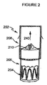
図2は、大動脈ステントグラフト202の形をとる補綴物装置の第一の実施の形態を示す。本実施の形態では、大動脈ステントグラフト202は、内側から外側へ順に、バルーン拡張型ステント204、導管206および自己拡張型ステント208を備える、同軸形状に配置された三つの略管状の部材を備える。導管206は人工弁210を含む。人工弁210は、開放された形状で示されており、矢印240により示される方向における、補綴物を経由した一方方向の血液の流れを可能にする。本実施の形態では、導管206は、薄肉の導管として示される。また本実施の形態では、人工弁210は、導管206の遠位端付近に示される。
FIG. 2 shows a first embodiment of a prosthetic device in the form of an
補綴物装置202の各部材の形状、大きさおよび寸法は変化してもよい。その結果として、大動脈ステントグラフト補綴物の全体としての大きさおよび形状が変化してもよい。好ましい補綴物装置の大きさは、主として、意図される埋め込み位置における管腔(好ましくは健康な弁/管腔の組合せ)の直径によって決定され、また、ステントおよび弁装置全体の望ましい長さによっても決定される。そのため、患者の本来の大動脈弁の位置に関する初期の評価によって、補綴物の構造に係る様々な局面が決定される。たとえば、患者の本来の大動脈弁の位置によって、ステントおよび管状導管の寸法、選択される弁の材料の種類、および留置手段の大きさが決定される。自己拡張型ステント208の長さは、導管206に重なり、上行大動脈118に係合するように延在するために、十分に長い。
The shape, size and dimensions of each member of the
図2に示す実施の形態では、導管206は、バルーン拡張型ステント204の長さを完全に被覆して示される。しかし、他の実施の形態では、導管206はバルーン拡張型ステント204の長さを部分的にのみ被覆してもよい。必要なのは、導管206の長さが、バルーン拡張型ステント204の少なくとも一部に重なり、これにより、補綴物を経由する流体の流れを設ける結合を提供するために、十分であることである。同様に、自己拡張型ステント208の長さも変化してもよい。必要なのは、自己拡張型ステント208の長さが、導管206に重なり、これにより、補綴物を経由する流体の流れを設ける結合を提供するために、十分であることである。
In the embodiment shown in FIG. 2, the
本実施の形態では、管状部材は好ましくは、軸方向に均一である。さらに、図2に示される管状部材は、およそ円筒形状に示される。他の実施の形態では、これらの管状部材の一つ以上は、曲線を付けて形成されてもよい。たとえば、これらの部材の一つ以上は、徐々に先細ってもよい。つまり、これらの部材は、遠位側へ徐々に狭まる管状、または遠位側へ徐々に広がる管状であってもよい。管状の部材はさらに、楕円状であってもよく、円錐状であってもよく、もしくは、移植患者の組織の形状に合う規則的な形状または不規則な形状の組合せを有してもよい。 In the present embodiment, the tubular member is preferably uniform in the axial direction. Furthermore, the tubular member shown in FIG. 2 is shown in a generally cylindrical shape. In other embodiments, one or more of these tubular members may be formed with a curve. For example, one or more of these members may taper gradually. That is, these members may have a tubular shape that gradually narrows toward the distal side, or a tubular shape that gradually widens toward the distal side. The tubular member may further be elliptical, conical, or have a regular shape or a combination of irregular shapes that match the shape of the tissue of the transplant patient.
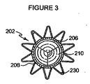
図3は、図2の補綴物の頂面図であり、閉塞された位置にある人工弁210を示している。この図において、人工弁210は、導管206に取り付けられるように見られる。本実施例に示される人工弁210は、三つの弁葉を含む。図3にはまた、自己拡張型ステント208が示される。図3に示されるように、複数の管状部材は、同軸でありおよそ円筒形状に示される。上述したように、他の実施例において、これらの管状部材の一つ以上は、曲線を付けて形成されてもよく、先細ってもよく、円錐状でもよく、または管腔の形状に合う不規則な形状を有してもよい。
FIG. 3 is a top view of the prosthesis of FIG. 2, showing the
図4は、図2の補綴物の底面図であり、閉塞された位置にある人工弁210を示している。この図には、導管206および自己拡張型ステント208に加えて、最も内側の部材であるバルーン拡張型ステント204が示される。
4 is a bottom view of the prosthesis of FIG. 2, showing the
これらの実施の形態の補綴物は、図5および図6に示すように、大動脈弁輪に達するように被験者の血管系内に導入され留置されてもよい。好ましくは補綴物は、送達のための圧縮された状態と、動脈の内部に留置されるときの拡張された状態とを有する。補綴物が大動脈弁輪の位置に留置され埋め込まれると、補綴物の人工弁は、被験者の大動脈弁を機能的に置換する。図5および図6に示された埋め込まれた補綴物の異なる実施の形態に留意する。図5では、自己拡張型ステント208は少なくとも部分的に管状導管206を囲み、管状導管206は少なくとも部分的にバルーン拡張型ステント204を囲む。図6では、バルーン拡張型ステント204と自己拡張型ステント208との両方が、少なくとも部分的に管状導管206を囲む。両方の実施の形態において、補綴物は、心臓から大動脈への流体の一方方向の流れを可能にする。
The prosthesis of these embodiments may be introduced and placed in the subject's vasculature to reach the aortic annulus, as shown in FIGS. Preferably, the prosthesis has a compressed state for delivery and an expanded state when placed within an artery. When the prosthesis is placed and implanted at the aortic annulus, the prosthetic prosthetic valve functionally replaces the subject's aortic valve. Note the different embodiments of the implanted prosthesis shown in FIGS. In FIG. 5, the self-expanding
補綴物を成す部材は、同時に導入され留置されてもよい。この状況では、各要素がバルーンカテーテルに装着されてもよい。バルーンは大動脈弁輪に配列され、その後拡張されて、実質的に同時に大動脈弁輪を拡張し、かつバルーン拡張型ステント204および補綴物の残りを留置する。弁輪が拡張されるのと同時に補綴物の各要素を実質的に同時に留置することにより、潜在的に致命的な逆流の問題を回避できる。
The members constituting the prosthesis may be introduced and placed at the same time. In this situation, each element may be attached to a balloon catheter. The balloon is arranged in the aortic annulus and then expanded to expand the aortic annulus substantially simultaneously and deploy the balloon
他の実施の形態では、個々の部材が順に導入され留置されてもよい。各要素が順に留置されるのであれば、大動脈弁輪を拡張しその後補綴物の要素を個々に挿入することに関連して、潜在的に致命的な大動脈弁逆流の問題のために、医師は血流を止める必要があるかもしれない。 In other embodiments, individual members may be introduced and placed in sequence. If each element is placed in turn, because of the potentially fatal aortic regurgitation problem associated with dilating the aortic annulus and then inserting the prosthetic elements individually, You may need to stop blood flow.
他の実施の形態では、同時および順の留置が組み合わせられてもよい。つまり、補綴物のいくつかの部材が同時に留置され、一方、他の一つまたは複数の部材が順に留置されてもよい。 In other embodiments, simultaneous and sequential placement may be combined. That is, several members of the prosthesis may be placed simultaneously, while the other member or members may be placed in turn.
補綴物に含まれる自己拡張型ステント208は、改良されたジアンタルコ(Gianturco)「Zステント」、または他の任意の形式の自己拡張型ステントであってもよい。Zステントの構造は、大きな径方向の力と長手方向の支持との両方を与えるので、大動脈の直線状の部分に好ましい。
The self-expanding
ある好ましい実施の形態では、自己拡張型ステント208は、図6および図7に示すように、編み組まれたステントであってもよい。図6および図7に図示されるように、長く目の粗い網状のステントは、弁が環状の取付具のみを介して支持されるのであれば必要とされるであろう支柱が無くとも、必要な下流側の支持を与える。このステントの構造には、柔軟性、圧縮力に対する抵抗、および組織を傷つけない大動脈との接合が必要とされる。自己拡張型ステントは、二つの区域、すなわち、径が小さく長さが一定の(圧縮に対する抵抗に係る)下側(近位側)区域と、径がより大きく長さが可変の(柔軟性に係る)上側(遠位側)区域と、を有してもよい。ウォールステント(Wallstent)のような編み組まれたステントは、編み組み角度を変えることによって、このような二つの区域を備えてもよい。ステントがニチノール製であるならば、金属線が全て曲げられ基本形状に接合された後に熱硬化することにより、正確な編み組み形状が決定されてもよい。ステントの近位端は、金属線の端部を輪として繋げることにより、より組織を傷つけないように形成されてもよい。
In certain preferred embodiments, the self-expanding
典型的には、血管管腔の略円形の断面に合わせるために、補綴物は完全に拡張されたとき円形の断面を有する。一実施例では、バルーン拡張型ステント204と自己拡張型ステント208とは、支柱と、鋭い曲がり、または、支柱が互いに角度を持って設置されたジグザグ形状に配置され、鋭い曲がりに結合された尖り、とを含んでもよい。ステントは、湾曲したまたは輪状の部分を含んでもよい。本実施の形態は、広範な種類のステントとともに使用されてもよい。これらのステントは、形状記憶合金ステントと、拡張型ステントと、その場で形成されるステントとを含むが、これらに限られるものではない。関連のある組織の空間に嵌合するための拡張に好適な、任意のステントの形状が使用されてもよい。
Typically, the prosthesis has a circular cross-section when fully expanded to conform to the generally circular cross-section of the vascular lumen. In one embodiment, the balloon
好ましくは、自己拡張型ステント208は、ニチノール、ステンレス鋼、またはエルジロイ(Elgiloy)から形成される。ステントを形成するために使用されてもよい他の材料の例は、カーボンまたは炭素繊維、タンタル、チタン、金、白金、インコネル、イリジウム、銀、タングステン、コバルト、クロム、セルロースアセテート、硝酸セルロース、シリコーン、ポリエチレンテレフタラート、ポリウレタン、ポリアミド、ポリエステル、ポリオルトエステル、ポリアンヒドリド、ポリエーテルスルホン、ポリカーボネート、ポリプロピレン、高分子量ポリエチレン、ポリテトラフルオロエチレン、またはその他の生体適合性重合体材料、もしくはこれらの混合物または共重合体;ポリ乳酸、ポリグリコール酸またはこれらの共重合体;ポリアンヒドリド、ポリカプロラクトン、ポリヒドロキシブチレートバリレート、を含む。さらに他の生体適合性金属、合金、もしくは他の生分解性の重合体または混合物または共重合体が使用されてもよい。
Preferably, the self-expanding
大動脈ステントグラフト202は、任意のステントの少なくとも一部に取り付けられた生体適合性グラフト材料を含んでもよい。グラフト材料は、人工弁に結合されてもよい。一実施の形態では、グラフト材料は管腔を形成し、その管腔は大動脈弁輪に対し近位側の位置における大動脈の壁を封止するために適応される。この実施の形態では、血液がステントグラフトの管腔を経由して流れ、人工弁は、補綴物を経由する血液の一方方向の流れを規制する。
生体適合性グラフト材料は好ましくは、生理的な力が加わることで漏れないように、無孔である。グラフト材料は好ましくは、織られたDACRON(登録商標)ポリエステル(英国、スコットランド、レンフルーシャーのVASCUTEK(登録商標)社)で形成される。好ましくは、グラフト材料は、継ぎ目無く形成される。管状のグラフトは、他のポリエステル織物、ポリテトラフルオロエチレン(PTFE)、拡張PTFE、および他の合成材料のような織物を含む、少なくとも実質的に生体適合性のある任意の他の材料から形成されてもよい。コラーゲンのような自然の生体材料、特に、小腸粘膜下組織(SIS)のような、細胞外マトリックス(ECM)として知られる生成されたコラーゲン材料もまた、非常に好ましい。弾性要素が、織物の特性として、または圧着などの後処理によって、組み入れられてもよい。グラフトの寸法は、治療される動脈の寸法に従って変化してもよい。各々の患者に対して、移植患者の動脈の径を超える径を有するグラフトが選択されてもよい。ステントは、グラフト材料と大動脈の内壁との間を封止させるために十分な径方向外向きの力を作用されることが期待される。 The biocompatible graft material is preferably nonporous so that it does not leak upon application of physiological forces. The graft material is preferably formed from woven DACRON® polyester (VASCUTEK®, Renfrewshire, Scotland, UK). Preferably, the graft material is formed seamlessly. The tubular graft is formed from any other material that is at least substantially biocompatible, including other polyester fabrics, fabrics such as polytetrafluoroethylene (PTFE), expanded PTFE, and other synthetic materials. May be. Also highly preferred are natural biomaterials such as collagen, especially produced collagen materials known as extracellular matrix (ECM), such as small intestine submucosa (SIS). Elastic elements may be incorporated as a property of the fabric or by a post treatment such as crimping. The size of the graft may vary according to the size of the artery to be treated. For each patient, a graft may be selected that has a diameter that exceeds the diameter of the transplant patient's artery. The stent is expected to be subjected to a sufficient radial outward force to seal between the graft material and the inner wall of the aorta.
大動脈ステントグラフトを動脈管腔の壁に固着するために、バルーン拡張型ステント204および/または自己拡張型ステント208は、好ましくは取付システムを含む。好ましい取付システムは、動脈壁係合部材、たとえば図2−4、8−11および16に示されるような、突起または棘部230を含む。
To secure the aortic stent graft to the wall of the arterial lumen, the balloon
好ましくは、鋭い金属製の棘部230は、補綴物202の表面から外方へ突き出る。棘部230は、補綴物202の一つ以上の部材に取り付けられてもよい。一実施の形態では、棘部230は、自己拡張型ステント208に取り付けられる。他の実施の形態では、棘部230は、バルーン拡張型ステント204に取り付けられる。さらに他の実施の形態では、棘部230は、自己拡張型ステント208とバルーン拡張型ステント204との両方に取り付けられる。棘部230は、尾側方向、頭側方向、または両方向に向く。棘部230は、ステントにはんだ付け、ロウ付けまたは溶着されてもよく、たとえばエッチングによって任意の点において一体に形成されてもよい。棘部の数は可変である。一実施の形態では、棘部230は自己拡張型ステント208から延び、留置されるときに上行大動脈の壁に係合してもよく、追加の棘部がバルーン拡張型ステント204から延び、冠状静脈洞に係合してもよい。大動脈ステントグラフトは、棘部を有してまたは有さずに使用されてもよい。棘部が省略される場合、冠状静脈洞および上行大動脈に作用する径方向の力が、バルーン拡張型ステント204および自己拡張型ステント208をそれぞれ所定の位置に保持するために十分であるように、ステントが形成されてもよい。
Preferably, the
図8および図9を参照して、矢印は、典型的な棘部230の外方向への曲がりを示す。点Aは、棘部230の尖を示し、点BおよびCは、棘部230のステントへの取り付け点を示す。留置時にステントが拡張すると、棘部230がステントの平面内に留まるのであれば、ΔAC(ACの差)はΔAB(ABの差)を上回らなければならない。しかし、ステント材料は伸長することも大きく順応することもできない。この差異は、図9および図10中の矢印に示されるように、棘部230の尖Aが外方向および下方向に動くことによって解決される。
With reference to FIGS. 8 and 9, the arrows indicate the outward bending of a
バルーンが無い場合、棘部230がステントの管腔内に移動することがある。棘部230が計画されたように動くことを確実にするために、図8−11に示すように、棘部230は、始点が外方向にわずかに曲がるように形成されてもよい。鋭い尖は、特に非常に短いステントにおいて、棘部として機能するために形成され得る。この実施の形態では、当初の曲がりがなおさら重要である。さもなければ、鋭い先端がバルーンをパンクさせてしまう。好ましい実施の形態では、図11に図示されるように、ステントは、拡張された状態で各々の尖から外方へ向く棘部230を有する。
In the absence of a balloon, the
上述されたように、大動脈ステントグラフト202は好ましくは、人工弁210を含む。この人工弁210の目的は、移植患者本来の損傷したまたは能力の低下した大動脈弁の機能を置換することである。人工弁210は好ましくは、心臓からより離れた導管206の遠位端に設置される。一実施例では、人工弁210は、導管206に縫合によって結合される。
As described above, the
人工弁210は好ましくは、一つ以上の弁葉を含む。自己拡張型ステント208の首部の反対側に長手方向に縫合された管状導管は、まさしく二尖弁として機能する。他の実施の形態では、三本の縫合線が、より冗長性の少ない三尖弁を生成する。好ましくは、図2−4に示すように、人工弁210は三つの弁葉を含む。弁葉が生来の大動脈弁を擬態するように、弁葉は補綴物内に配置される。人工弁210の近位側の圧力が人工弁の遠位側の圧力を上回るとき、人工弁210が「開き」、血液が流れる。このようにして、人工弁210は、心臓から大動脈への流体の一方方向の流れを規制する。
人工弁210の弁葉は、たとえばポリエステル織物、ポリテトラフロオロエチレン(PTFE)、拡張PTFEのような材料、およびその他の当該技術分野における当業者に公知の合成材料を含む、少なくとも実質的に生体適合性の材料から製造されてもよい。好ましくは、弁葉は、自然の生体材料から製造される。弁葉は、細胞外マトリックスのような、生成されたコラーゲン材料を含んでもよい。細胞外マトリックスは、小腸粘膜下組織、胃粘膜下組織、心膜、肝臓基底膜、膀胱粘膜下組織、組織粘膜、硬膜などであってもよい。
The leaflets of the
正常な本来の大動脈弁は、冠動脈口の間の管状静脈洞の壁への取付具を介して上方から吊り下げられ、弁輪の中の空間を満たすための完全な寸法および形状の弁葉を有する。吊り下げられた弁は、下流側の支持部への取付具を介して、心臓拡張期の血圧によって生じ閉じられた弁葉へ作用する力に抵抗するものの、ちょうど近代のステントの支柱が織物を支持するように、人工弁の膜状の「弁葉」を下方から支持することもまた可能である。この方法は以下に述べられ、弁の基底が広く、下流側の固着のために好適な場所がほとんどない場所において、特に利点を有する。 A normal native aortic valve is hung from above via a fitting to the wall of the tubular sinus between the coronary ostium and has a complete sized and shaped leaflet to fill the space in the annulus. Have. Although the hung valve resists the force acting on the closed leaflets caused by diastolic blood pressure via the attachment to the downstream support, the struts of modern stents just woven the fabric. It is also possible to support the membrane “valve” of the prosthetic valve from below so as to support it. This method is described below and is particularly advantageous where the valve base is wide and there are few suitable locations for downstream anchoring.
種々の人工弁の構造が使用されてもよい。これらの構造は好ましくは、一方側から他方側への直接の経路がないように穴/隙間/蓋に重なる、少なくとも二つの膜を有する。流れの段階(大動脈弁の収縮期、僧帽弁の拡張期)において、膜は下方の支持部から持ち上がり、離れ、血液がこれらの孔を経由して抜けられるようにする。外側の膜が内側の膜よりもわずかにたるんでいれば、これが最もよく作用する。広範な種類の隙間および蓋が使用可能である。 Various artificial valve structures may be used. These structures preferably have at least two membranes that overlap the hole / gap / lid so that there is no direct path from one side to the other. During the flow phase (aortic valve systole, mitral valve diastole), the membrane lifts from the underlying support and leaves, allowing blood to escape through these holes. This works best if the outer membrane is slightly slacker than the inner membrane. A wide variety of gaps and lids can be used.
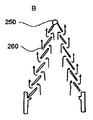
図12に示す実施例では、内側の膜は中心孔250を有し、外側の膜は液体の通路となり得る一連の周辺隙間260を有する。いくつかの実施の形態では、隙間260は、介在する織物が一連の放射状の綱のみであるように、外側部分のほぼ全領域に形成されてもよい。図12は、そのような人工弁の、A)拡張期およびB)収縮期の動作を図示する。図12B中の矢印は、隙間を経由し、そのため収縮期に弁を経由して流れる血流の方向を示す。
In the embodiment shown in FIG. 12, the inner membrane has a
人工弁の蓋は、柔らかい膜である必要はない。弁の蓋は、原始的な周辺の取付機構の存在下で、それ自身を支持するために、いくらか剛性を有してもよい。一つの円盤が、平らにされた腕時計のばねのような螺旋状のひもから、その場で形成されてもよい。弁全体が円錐状であれば、拡張期の圧力勾配によって生じた長手方向の力は、強固なステントが弁輪に機構を固着させる場所である、縁部に伝えられる。コイル層を分離させることで、収縮期に流れが生じる。 The prosthetic valve lid need not be a soft membrane. The valve lid may be somewhat rigid to support itself in the presence of a primitive peripheral attachment mechanism. A single disk may be formed in situ from a spiral strap, such as a flattened watch spring. If the entire valve is conical, the longitudinal force created by the diastolic pressure gradient is transmitted to the edge, where the rigid stent anchors the mechanism to the annulus. By separating the coil layers, a flow occurs during the systole.
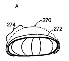
いくつかの実施の形態では、人工弁210のための固着/支持枠組みは、図13〜15に一部が図示されるように、たとえば円筒状、扁平な球状、ドーナツ状、二重円盤状などの、多くの形状をとることができる。これら全ての中で、ドーナツ形状は、膜の下側に直接接触することよりも、弁の膜をぴんと張ることによって、より大きな支持を与える。図13に、網状の球またはドーナツ形状の一実施例が示され、外側の膜270、内側の膜272および放射状の隙間274の位置が図示されている。
In some embodiments, the anchoring / support framework for the
図14に示すように、二重円盤形は、弁としてではなく遮壁または障壁として機能するための、実質的に完全に不浸透性の(隙間または穴の無い)被覆を有して形成され得る。実際には、血管内の空間を閉止するために、弁の一方側が他方側よりも薄くてもよい。薄い側は空間の外側に設置され、滑らかで平らな表面を示す。厚い側は空間の内側に設置され空間を閉止し、またその一方で安定性を与える。 As shown in FIG. 14, the double disc shape is formed with a substantially completely impervious (no gap or hole) coating to function as a barrier or barrier rather than as a valve. obtain. In practice, one side of the valve may be thinner than the other side to close the space in the blood vessel. The thin side is placed outside the space and exhibits a smooth and flat surface. The thicker side is placed inside the space and closes the space, while providing stability.
図14には、弁膜280および本来の大動脈弁282の位置が図示される。血流の方向は矢印284で示される。網状の球である弁の構造は、たとえば図14に示す構造のように、織物の金属線を円盤の縁において始端および終端させることの利益を享受する。これらは周辺の組織(または二重円盤形の場合、介在する組織)を突き刺し、網を所定の位置に縫合する傾向がある。
FIG. 14 illustrates the position of the
概して、支持枠は網状の球または円盤のみである必要はない。いくつかの実施の形態では、図15に示すように、たとえば金属線にまたがるGreenfield(登録商標)フィルタと同様に、膜は円錐状(テント状)であってもよい。図15には、弁膜292、傘状枠294、および一つ以上の取り付け鉤296が図示される。
In general, the support frame need not be only a reticulated sphere or disk. In some embodiments, as shown in FIG. 15, the membrane may be conical (tent-like), for example, similar to a Greenfield® filter spanning a metal wire. In FIG. 15, a
大動脈ステントグラフトは、留置装置または導入器を使用して、移植患者の血管系に導入され、送達され、留置される。留置装置は、図5および図6に示すように、大動脈内部の大動脈弁に置換するための位置に大動脈ステントグラフトを送達し留置する。留置装置は、腹部を切開して管腔内の送達および留置を行なうための形状および寸法とされてもよい。典型的には、留置装置は、カニューレまたはカテーテルを含み、種々の形状を有することができる。大動脈ステントグラフトは、従来の方法を使用して、径方向に折り畳まれてカテーテルまたはカニューレの内部に挿入されてもよい。カニューレまたはカテーテルに加えて、意図された目的のために最も好適な送達および留置システムを得るために、種々の他の要素を設けることを必要としてもよい。これらは、種々の外部シース、押し込み具、ストッパ、ガイドワイヤ、センサなどを含むが、これらに限られるものではない。 The aortic stent graft is introduced, delivered, and deployed into the vascular system of the implanted patient using an indwelling device or introducer. The indwelling device delivers and deploys the aortic stent graft in a position to replace the aortic valve inside the aorta, as shown in FIGS. The indwelling device may be shaped and dimensioned for incision in the abdomen for delivery and placement in the lumen. Typically, indwelling devices include cannulas or catheters and can have a variety of shapes. The aortic stent graft may be folded radially and inserted into the catheter or cannula using conventional methods. In addition to the cannula or catheter, it may be necessary to provide various other elements in order to obtain the most suitable delivery and placement system for the intended purpose. These include, but are not limited to, various external sheaths, pushers, stoppers, guide wires, sensors, and the like.
管腔内装置のための送達システムの例は、当該技術分野で公知である。米国特許出願公開第2003/0149467号明細書「ステントの送達のための方法、システムおよび装置」は、利用可能なステント送達システムの例を与える。管腔内装置の送達に関するシステムおよび方法の他の例は、米国特許第6695875号明細書「管腔内ステントグラフト」に、既に説明された。国際公開第98/53761号「補綴物および補綴物の留置方法」は、両端を独自に動かせるように補綴物を保持する、補綴物の導入器を開示する。同様に、ゼニス(登録商標)TAA血管内グラフトは、インディアナ州ブルーミントンのクック社から市販されている送達装置を使用する。 Examples of delivery systems for intraluminal devices are known in the art. United States Patent Application Publication No. 2003/0149467, “Methods, Systems, and Devices for Delivery of Stents” provides examples of available stent delivery systems. Another example of a system and method for delivery of an endoluminal device has already been described in US Pat. No. 6,695,875 “Intraluminal Stent Graft”. WO 98/53761 “Prosthesis and prosthesis placement method” discloses a prosthesis introducer that holds the prosthesis so that both ends can be moved independently. Similarly, Zenith® TAA endovascular graft uses a delivery device commercially available from Cook Company, Bloomington, Indiana.
一実施の形態では、ステントグラフトの保持された端部を解放するために、トリガワイヤ解放機構が設けられる。トリガワイヤ解放機構は、ステントグラフト保持装置と、ステントグラフトをステントグラフト保持装置に結合するトリガワイヤと、トリガワイヤをステントグラフト保持装置から分離するための制御部材と、を含む。好ましくは、トリガワイヤ装置は、解放機構から留置装置を経由して延びる、少なくとも一つのトリガワイヤを含む。トリガワイヤは、大動脈ステントグラフトの近位端に係合される。好ましい実施の形態では、大動脈ステントグラフトはモジュール式であり多数の部分を含むが、解放機構から留置装置を経由して延びる多数のトリガワイヤがあり、トリガワイヤの各々は大動脈ステントグラフトの少なくとも一部に係合してもよい。好ましくは、大動脈ステントグラフトは、三つの部材(バルーン拡張型ステント、導管、自己拡張型ステント)を含む。そのため、好ましい実施の形態では、三本のトリガワイヤがこれらの補綴物の三つの部材の各々に個々に係合する。補綴物の部材の各々の留置を個々に制御することにより、全体として補綴物の留置のより良い制御が可能になる。 In one embodiment, a trigger wire release mechanism is provided to release the retained end of the stent graft. The trigger wire release mechanism includes a stent graft retention device, a trigger wire that couples the stent graft to the stent graft retention device, and a control member for separating the trigger wire from the stent graft retention device. Preferably, the trigger wire device includes at least one trigger wire extending from the release mechanism via the indwelling device. The trigger wire is engaged to the proximal end of the aortic stent graft. In a preferred embodiment, the aortic stent graft is modular and includes multiple portions, but there are multiple trigger wires extending from the release mechanism through the indwelling device, each of the trigger wires engaging at least a portion of the aortic stent graft. May be. Preferably, the aortic stent graft comprises three members (balloon expandable stent, conduit, self-expanding stent). Thus, in a preferred embodiment, three trigger wires individually engage each of the three members of these prostheses. By individually controlling the placement of each of the members of the prosthesis, overall control of the placement of the prosthesis is possible.
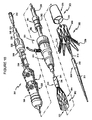
図16は、上述された大動脈ステントグラフトを留置するために使用される典型的な導入器を示す。導入器は、医療処置中に患者の動脈管腔内へ大動脈ステントグラフト202を留置するために使用される。導入器は、外部操作部301と、近位側位置決め機構または取り付け領域302とを含む。導入器はまた、遠位側位置決め機構または取り付け領域303を有する。大動脈ステントグラフトを留置するための医療処置中に、近位側取り付け領域302と遠位側取り付け領域303とは、動脈管腔を経由して所望の留置位置にまで移動する。外部操作部301は、この導入器を操作する使用者によって作動されるが、処置の間中患者の体外に保たれる。
FIG. 16 shows a typical introducer used to deploy the aortic stent graft described above. The introducer is used to place the
図16に図示されるように、大動脈ステントグラフト202は、シース330によって圧縮された状態に保持される。シース330は、薄肉管315の遠位側部分を超えて、大動脈ステントグラフト202を径方向に圧縮する。薄肉管315は、概して柔軟性であり、金属を含んでもよい。管341は、樹脂で形成されてもよいが、薄肉管315と同軸であり、薄肉管315の径方向外側にある。管341の遠位端は、大動脈ステントグラフト202の近位端に隣接する。管341は、送達中にステントグラフト202を導入器から解放するための押し込み具として作用する。
As illustrated in FIG. 16, the
管341は「厚肉である」。つまり、管341の壁の厚さは、薄肉管315の壁の厚さの数倍である。好ましくは、管341は、薄肉管315よりも5倍以上厚い。シース330は、厚肉管341と同軸であり、厚肉管341の径方向外側に位置する。厚肉管341とシース330とは、図16に示すように、外部操作部301まで近位側に延びる。薄肉管315は、導入器の近位端まで延びる。導入器はさらに、シースおよび厚肉管341の周囲に径方向に配置される止血シール手段331を含む。止血シール手段331は、処置中の導入器を介する血液の損失を制御する。
The
導入器は、図16に図示されるように、大動脈ステントグラフト制御部材381を含んでもよい。ステントグラフト制御部材381は、外部操作部301の拡張器部分334上に配置される。大動脈ステントグラフト202の留置中に、シース330は厚肉管341を超えて近位側へ引き抜かれる。止血シール手段331は概して、シース330の周囲にしっかりと嵌合し、シース330と厚肉管341との間の大きな摩擦を形成する。結果として、厚肉管341を超えてシース330を引き抜くのは困難である。この摩擦に打ち勝つために、操作者は、厚肉管341を非常にきつく把持しなければならない。厚肉管341の把持が困難であるために、大動脈ステントグラフト202の軸方向位置が損なわれることがある。制御部材381は、操作者に拡張器をよりよく把持させ、シース330の引き抜き中に厚肉管341を制御し安定させるために操作者が加えなければならない力を低減することによって、この問題を解決する。制御部材381は略管状であり、内側の拡張器対向面382と外側の把持面383とを含む。制御部材381は、拡張器に沿う任意の位置において操作者が制御部材381を使用することを可能にするために、止血シール手段331と解放ワイヤ作動部との間で、厚肉管341上にスライド可能に配置される。
The introducer may include an aortic stent graft control member 381 as illustrated in FIG. The stent graft control member 381 is disposed on the dilator portion 334 of the
外側の把持面383は、制御部材381が操作者の手に快適にかつしっかりと嵌るように設計される。このようにして、外側の把持面383は、厚肉管341の径を大きく超える径を有してもよい。外側の把持面383は、概して軸方向に均一であってもよい。他の実施の形態では、外側の把持面383は、概して軸方向に非均一であり、その結果として曲線を付けて形成された把持面をもたらしてもよい。図16は、概して非均一な外側の把持面383を有する制御部材381を図示する。図16では、制御部材381は、概して砂時計のような形状である。外側の把持面383は、滑らかな表面仕上げを含んでもよく、または代替的には、外側の把持面は粗いまたはざらざらの表面仕上げを含んでもよい。粗いまたはざらざらの表面仕上げは有益である。なぜなら、操作者と制御部材381との間の接触表面積を増加させ、これにより操作者の影響力が増加するためである。種々の実用的および触覚的な利益を与えるための多数の表面仕上げが選択されてもよい。
The outer
制御部材381は、操作者が制御部材381を把持するとき制御部材381が厚肉管341を圧縮するように、概して変形可能である。制御部材381は、操作者によって加えられた力を厚肉管341に伝える。拡張器対向面382は、概して滑らかな表面を含んでもよい。代替的には、拡張器対向面382は、粗いまたはざらざらの表面を有してもよい。粗いまたはざらざらの表面は、制御部材381と厚肉管341との間に、より「粘着性の」または「べたつく」接触を形成し、これにより操作者によって拡張器に伝えられる力を増大させてもよい。
The control member 381 is generally deformable such that the control member 381 compresses the
拡張器対向面382は、概して均一の表面を含んでもよい。代替的には、拡張器対向面382は、概して非均一の表面を含んでもよい。たとえば、拡張器把持面382は、厚肉管341へ向かって径方向内方へ延びる、複数の係合可能な突起を含んでもよい。操作者が厚肉管341に対して制御部材381を把持するとき、係合可能な突起は厚肉管の表面に係合する。係合可能な突起は、制御部材381と厚肉管との間の接触表面積を増大させ、これにより制御部材が操作者から厚肉管341へ伝える力を増大させる。係合可能な突起は、任意の幾何学的または非幾何学的な形状を含んでもよい。たとえば、係合可能な突起は、「O」字形状、線状、点線状、「V」字形状などを含んでもよい。
The
遠位側取り付け領域303は、保持装置310を含む。保持装置310は、大動脈ステントグラフトの遠位端を圧縮された状態で保持する。保持部材310は、その遠位端において、長い先細り形状の可撓性延長部311を含む。可撓性延長部311は、事前に挿入されたガイドワイヤに沿う先細り形状の可撓性延長部311の前進を容易にする、内部の長手方向の穴を含む。長手方向の穴はまた、治療薬の導入のための通路を設ける。たとえば、医療処置の設置および留置段階の間に血管造影を行なうための造影剤を供給することが望ましい。
The
薄肉管315の遠位端は、可撓性延長部311に結合される。薄肉管315は、導入器が容易に前進できるように、可撓性を有する。薄肉管は、近位側に導入器を経由して操作部301まで延び、連結手段316において終端する。薄肉管315は、可撓性延長部と機械的に連通し、操作者が大動脈ステントグラフト202に関して遠位側取り付け領域303を軸方向および回転方向に操作するのを可能にする。連結手段316は、注射器を受け容れ、薄肉管315への試薬の導入を容易にするために、適用される。薄肉管315は可撓性延長部311と流体連通し、可撓性延長部311は穴を経由して動脈管腔内へ試薬を導入する。
The distal end of
外部操作部301のトリガワイヤ解放作動部は、細長体336を含む。遠位側トリガワイヤ解放機構324と近位側トリガワイヤ解放機構325とは、細長体336上に配置される。端部キャップ338は、細長体336の近位端および遠位端に配置される。端部キャップ338は、遠位側栓388と近位側栓389とを規定する、長手方向に面する平行対向面を含む。遠位側トリガワイヤ解放機構324と近位側トリガワイヤ解放機構325とは、遠位側栓388と近位側栓389との間の細長体336上に、スライド可能に配置される。遠位側栓388と近位側栓389とは、遠位側トリガワイヤ解放機構324と近位側トリガワイヤ解放機構325とを、細長体336上に保持する。作動部は、細長体336上のトリガワイヤ解放機構324,325の軸方向の変位を制限するための、ロック機構を含む。
The trigger wire release operation part of the
外部操作部301を参照して、ピン万力339は細長体336の近位端に装着される。ピン万力339は、ねじ蓋346を有する。ねじこまれたとき、万力のアゴは薄肉金属管315を締め付ける(係合する)。万力のアゴが係合されたとき、薄肉管315は細長体336とともにのみ移動できる。したがって薄肉管315は、厚肉管341とともにのみ移動できる。ねじ蓋346を閉めることにより、組立部品の全体がシース330に関して一体として移動できる。
Referring to the
自己拡張型ステント208は、図16に示すように、導入器301からの解放中に、大動脈ステントグラフト202を拡張させる。本実施例に示されるステントグラフトはまた、自己拡張型ステント208の遠位端から延びる棘部230を含む。自己拡張型ステント208が留置される(解放される)とき、棘部230は大動脈ステントグラフト202の遠位端を周辺の管腔(図示せず)に固着する。管腔内の留置の際に、バルーン拡張型ステント204が膨張し拡張する。ステントの両端がそれぞれのスリーブから引き抜かれ、ステントが解放されて所定の位置へ拡張するように、スリーブ間のカテーテルの膨張によってバルーン拡張型ステントの拡張が引き起こされてもよい。管状導管206もまた、導入器からの解放の際に拡張される。管状導管206がバルーン拡張型ステント204と自己拡張型ステント208との間に位置決めされ、これら二つのステントに接触するとき、これら二つのステント204,208の拡張が管状導管206の拡張を同様にもたらす。好ましくは、管状導管206は薄肉であり、このことが解放されるときの拡張に役立つ。
Self-expanding
本発明の種々の実施の形態が説明されたが、本発明は、添付の特許請求の範囲およびその均等物を考慮して、これらの他には限定されるべきではない。さらに、本明細書中に説明された利点は必ずしも本発明の唯一の利点ではなく、本発明の各実施の形態が説明された利点の全てを達成することは必ずしも期待されない。 While various embodiments of the invention have been described, the invention should not be limited in any other way in view of the appended claims and their equivalents. Further, the advantages described herein are not necessarily the only advantages of the present invention, and it is not necessarily expected that each embodiment of the invention will achieve all of the described advantages.
本発明書中に説明された異なる実施の形態の特徴が、任意の適切な方法で互いに組み合わされてもよく、そのため、一実施の形態に関連して説明された特徴が当該実施の形態のみに関して使用されることに限定されないことを理解されたい。 The features of the different embodiments described in this document may be combined with each other in any suitable manner, so that the features described in connection with one embodiment relate only to that embodiment. It should be understood that the invention is not limited to being used.
人工弁210は通常、心臓の弁を物理的に置換せず、心臓の弁は外科的に触れられないままとされ、人工弁210は、心臓の弁に付加されて心臓の弁の機能を果たすことをまた理解されたい。しかしながら、人工弁210が心臓の弁を物理的に置換することは除外されない。
The
一つよりも多い弁が補綴物に設けられることは除外されない。
本特許出願は、2007年11月9日に出願され、「大動脈弁ステントグラフト」と題された米国仮出願第60/986908号の優先権の利益を主張し、当該仮出願の開示はその全体が引用により援用される。
It is not excluded that more than one valve is provided in the prosthesis.
This patent application claims priority benefit of US Provisional Application No. 60/986908, filed Nov. 9, 2007 and entitled “Aortic Valve Stent Graft”, the disclosure of which is in its entirety. Incorporated by reference.
Claims (7)
第一ステントと、
大動脈弁置換物が設けられた管状導管とを含み、前記管状導管の少なくとも一部は前記第一ステントの少なくとも一部に重なり、前記大動脈弁置換物は前記第一ステントを超えて延在し、さらに、
前記管状導管の少なくとも一部に重なるように動作可能な、前記管状導管を超えて延在する第二ステントを含み、
前記第一ステントと前記管状導管と前記第二ステントとは、前記補綴物を経由して流体を一方方向に通すために、同軸に配置され、
前記第一ステントはバルーン拡張型ステントを備え、前記第二ステントは自己拡張型ステントを備え、
前記第一ステントと前記第二ステントとの間に重なりがない、管腔内補綴物。 An endoluminal prosthesis,
A first stent;
A tubular conduit provided with an aortic valve replacement, wherein at least a portion of the tubular conduit overlaps at least a portion of the first stent, and the aortic valve replacement extends beyond the first stent; further,
A second stent extending beyond the tubular conduit, operable to overlap at least a portion of the tubular conduit;
The first stent, the tubular conduit, and the second stent are arranged coaxially to pass fluid in one direction through the prosthesis;
The first stent comprises a balloon expandable stent and the second stent comprises a self-expanding stent;
An endoluminal prosthesis with no overlap between the first stent and the second stent.
Applications Claiming Priority (3)
| Application Number | Priority Date | Filing Date | Title |
|---|---|---|---|
| US98690807P | 2007-11-09 | 2007-11-09 | |
| US60/986,908 | 2007-11-09 | ||
| PCT/US2008/012500 WO2009061419A1 (en) | 2007-11-09 | 2008-11-06 | Aortic valve stent graft |
Publications (3)
| Publication Number | Publication Date |
|---|---|
| JP2011502628A JP2011502628A (en) | 2011-01-27 |
| JP2011502628A5 JP2011502628A5 (en) | 2011-08-11 |
| JP5238932B2 true JP5238932B2 (en) | 2013-07-17 |
Family
ID=40269460
Family Applications (1)
| Application Number | Title | Priority Date | Filing Date |
|---|---|---|---|
| JP2010533092A Active JP5238932B2 (en) | 2007-11-09 | 2008-11-06 | Aortic valve stent graft |
Country Status (6)
| Country | Link |
|---|---|
| US (4) | US8715337B2 (en) |
| EP (1) | EP2217174B1 (en) |
| JP (1) | JP5238932B2 (en) |
| CN (1) | CN101896139B (en) |
| AU (1) | AU2008325202B2 (en) |
| WO (1) | WO2009061419A1 (en) |
Families Citing this family (126)
| Publication number | Priority date | Publication date | Assignee | Title |
|---|---|---|---|---|
| US9408607B2 (en) | 2009-07-02 | 2016-08-09 | Edwards Lifesciences Cardiaq Llc | Surgical implant devices and methods for their manufacture and use |
| US8252036B2 (en) | 2006-07-31 | 2012-08-28 | Syntheon Cardiology, Llc | Sealable endovascular implants and methods for their use |
| US9585743B2 (en) | 2006-07-31 | 2017-03-07 | Edwards Lifesciences Cardiaq Llc | Surgical implant devices and methods for their manufacture and use |
| DE102007019058A1 (en) * | 2007-04-23 | 2008-10-30 | Stengel, Max, Dr.Dr. | Vascular implant for the treatment of an aneurysm |
| US9814611B2 (en) | 2007-07-31 | 2017-11-14 | Edwards Lifesciences Cardiaq Llc | Actively controllable stent, stent graft, heart valve and method of controlling same |
| US9566178B2 (en) | 2010-06-24 | 2017-02-14 | Edwards Lifesciences Cardiaq Llc | Actively controllable stent, stent graft, heart valve and method of controlling same |
| US8679176B2 (en) | 2007-12-18 | 2014-03-25 | Cormatrix Cardiovascular, Inc | Prosthetic tissue valve |
| US8257434B2 (en) | 2007-12-18 | 2012-09-04 | Cormatrix Cardiovascular, Inc. | Prosthetic tissue valve |
| CN102292053A (en) | 2008-09-29 | 2011-12-21 | 卡迪尔克阀门技术公司 | Heart valve |
| WO2010040009A1 (en) | 2008-10-01 | 2010-04-08 | Cardiaq Valve Technologies, Inc. | Delivery system for vascular implant |
| PL3000472T3 (en) * | 2009-02-18 | 2017-09-29 | Cormatrix Cardiovascular, Inc. | Compositions for preventing atrial and ventricular fibrillation |
| CA2961053C (en) | 2009-04-15 | 2019-04-30 | Edwards Lifesciences Cardiaq Llc | Vascular implant and delivery system |
| US9468515B2 (en) * | 2009-07-01 | 2016-10-18 | Correx, Inc. | Method and apparatus for effecting a percutaneous aortic valve bypass |
| US10034748B2 (en) | 2009-09-18 | 2018-07-31 | The Regents Of The University Of California | Endovascular prosthetic heart valve replacement |
| US9095456B2 (en) | 2009-10-13 | 2015-08-04 | Cook Medical Technologies Llc | Paraplegia prevention stent graft |
| AU2010306961B2 (en) | 2009-10-13 | 2013-10-10 | Cook Medical Technologies Llc | Paraplegia prevention stent graft |
| AU2015230879B2 (en) * | 2009-12-08 | 2017-06-15 | Avalon Medical Ltd. | Device and system for transcatheter mitral valve replacement |
| US8870950B2 (en) | 2009-12-08 | 2014-10-28 | Mitral Tech Ltd. | Rotation-based anchoring of an implant |
| WO2011111047A2 (en) | 2010-03-10 | 2011-09-15 | Mitraltech Ltd. | Prosthetic mitral valve with tissue anchors |
| US8579964B2 (en) | 2010-05-05 | 2013-11-12 | Neovasc Inc. | Transcatheter mitral valve prosthesis |
| US11653910B2 (en) | 2010-07-21 | 2023-05-23 | Cardiovalve Ltd. | Helical anchor implantation |
| US9763657B2 (en) | 2010-07-21 | 2017-09-19 | Mitraltech Ltd. | Techniques for percutaneous mitral valve replacement and sealing |
| EP2422748B1 (en) * | 2010-08-31 | 2016-01-27 | Biotronik AG | Medical implant, particularly valve implant, for implantation in an animal and/or human body and method, particularly production method, for producing an implantation apparatus for the medical implant |
| US20120116496A1 (en) | 2010-11-05 | 2012-05-10 | Chuter Timothy A | Stent structures for use with valve replacements |
| EP2640319B1 (en) * | 2010-11-16 | 2016-10-19 | TriVascular, Inc. | Advanced endovascular graft and delivery system |
| DE102011009555A1 (en) * | 2011-01-21 | 2012-07-26 | Aesculap Ag | Vascular prosthesis with integrated aortic valve |
| EP2517671B1 (en) | 2011-04-28 | 2016-05-11 | Cook Medical Technologies LLC | Apparatus for facilitating deployment of an endoluminal prosthesis |
| US9554897B2 (en) | 2011-04-28 | 2017-01-31 | Neovasc Tiara Inc. | Methods and apparatus for engaging a valve prosthesis with tissue |
| US9308087B2 (en) | 2011-04-28 | 2016-04-12 | Neovasc Tiara Inc. | Sequentially deployed transcatheter mitral valve prosthesis |
| JP2014533119A (en) | 2011-05-27 | 2014-12-11 | コーマトリックス カーディオバスキュラー, インコーポレイテッドCorMatrix Cardiovascular, Inc. | Valve conduit for extracellular matrix material and method for making the same |
| CA2855943C (en) | 2011-07-29 | 2019-10-29 | Carnegie Mellon University | Artificial valved conduits for cardiac reconstructive procedures and methods for their production |
| WO2013021374A2 (en) | 2011-08-05 | 2013-02-14 | Mitraltech Ltd. | Techniques for percutaneous mitral valve replacement and sealing |
| US8852272B2 (en) | 2011-08-05 | 2014-10-07 | Mitraltech Ltd. | Techniques for percutaneous mitral valve replacement and sealing |
| EP2739214B1 (en) | 2011-08-05 | 2018-10-10 | Cardiovalve Ltd | Percutaneous mitral valve replacement and sealing |
| US9827093B2 (en) | 2011-10-21 | 2017-11-28 | Edwards Lifesciences Cardiaq Llc | Actively controllable stent, stent graft, heart valve and method of controlling same |
| DE202012013754U1 (en) | 2011-12-06 | 2021-03-01 | Aortic Innovations Llc | Device for endovascular aortic repair |
| FR2985659B1 (en) * | 2012-01-13 | 2015-03-06 | Assist Publ Hopitaux De Paris | DEVICE FOR ANCHORING A PROTHETIC CARDIAC VALVE. |
| US9839519B2 (en) | 2012-02-29 | 2017-12-12 | Valcare, Inc. | Percutaneous annuloplasty system with anterior-posterior adjustment |
| US9180008B2 (en) | 2012-02-29 | 2015-11-10 | Valcare, Inc. | Methods, devices, and systems for percutaneously anchoring annuloplasty rings |
| EP2886083B1 (en) * | 2012-03-23 | 2018-05-16 | Sorin Group Italia S.r.l. | A collapsible valve prosthesis |
| US8992595B2 (en) | 2012-04-04 | 2015-03-31 | Trivascular, Inc. | Durable stent graft with tapered struts and stable delivery methods and devices |
| US9498363B2 (en) | 2012-04-06 | 2016-11-22 | Trivascular, Inc. | Delivery catheter for endovascular device |
| US9345573B2 (en) | 2012-05-30 | 2016-05-24 | Neovasc Tiara Inc. | Methods and apparatus for loading a prosthesis onto a delivery system |
| US9301835B2 (en) | 2012-06-04 | 2016-04-05 | Edwards Lifesciences Corporation | Pre-assembled bioprosthetic valve and sealed conduit |
| ES2735536T3 (en) | 2012-08-10 | 2019-12-19 | Sorin Group Italia Srl | A valve prosthesis and a kit |
| US9585748B2 (en) | 2012-09-25 | 2017-03-07 | Edwards Lifesciences Corporation | Methods for replacing a native heart valve and aorta with a prosthetic heart valve and conduit |
| EP2948103B1 (en) | 2013-01-24 | 2022-12-07 | Cardiovalve Ltd | Ventricularly-anchored prosthetic valves |
| KR101415578B1 (en) * | 2013-01-28 | 2014-07-09 | 이화여자대학교 산학협력단 | Apparatus for stent with reflux prevention function |
| US9095344B2 (en) | 2013-02-05 | 2015-08-04 | Artventive Medical Group, Inc. | Methods and apparatuses for blood vessel occlusion |
| US8984733B2 (en) | 2013-02-05 | 2015-03-24 | Artventive Medical Group, Inc. | Bodily lumen occlusion |
| WO2014133543A1 (en) * | 2013-03-01 | 2014-09-04 | Cormatrix Cardiovascular, Inc. | Two-piece prosthetic valve |
| US10588746B2 (en) * | 2013-03-08 | 2020-03-17 | Carnegie Mellon University | Expandable implantable conduit |
| US10583002B2 (en) | 2013-03-11 | 2020-03-10 | Neovasc Tiara Inc. | Prosthetic valve with anti-pivoting mechanism |
| US9681951B2 (en) | 2013-03-14 | 2017-06-20 | Edwards Lifesciences Cardiaq Llc | Prosthesis with outer skirt and anchors |
| EP2967700B1 (en) | 2013-03-15 | 2020-11-25 | Valcare, Inc. | Systems for delivery of annuloplasty rings |
| CN110393608B (en) | 2013-03-15 | 2023-02-17 | 心脏结构导航公司 | Catheter-guided valve replacement devices and methods |
| US9572665B2 (en) | 2013-04-04 | 2017-02-21 | Neovasc Tiara Inc. | Methods and apparatus for delivering a prosthetic valve to a beating heart |
| US10034784B2 (en) | 2013-04-17 | 2018-07-31 | Gilbert H. L. Tang | Heart valve and endovascular graft components and method for delivery |
| EP3003187B1 (en) | 2013-05-24 | 2023-11-08 | Valcare, Inc. | Heart and peripheral vascular valve replacement in conjunction with a support ring |
| US9636116B2 (en) | 2013-06-14 | 2017-05-02 | Artventive Medical Group, Inc. | Implantable luminal devices |
| US9737306B2 (en) | 2013-06-14 | 2017-08-22 | Artventive Medical Group, Inc. | Implantable luminal devices |
| US10149968B2 (en) | 2013-06-14 | 2018-12-11 | Artventive Medical Group, Inc. | Catheter-assisted tumor treatment |
| EP3013253B1 (en) | 2013-06-28 | 2021-01-06 | ValCare, Inc. | Device for securing an article to a tissue |
| US9861474B2 (en) * | 2013-07-18 | 2018-01-09 | The Trustees Of The University Of Pennsylvania | Cardiac repair prosthesis sets and methods |
| EP2835112B1 (en) | 2013-08-08 | 2021-01-27 | Sorin Group Italia S.r.l. | Heart valve prosthesis |
| CN106456321B (en) | 2014-05-14 | 2019-08-27 | 索林集团意大利有限责任公司 | It is implanted into equipment and implantation external member |
| WO2016016899A1 (en) | 2014-07-30 | 2016-02-04 | Mitraltech Ltd. | Articulatable prosthetic valve |
| EP2982336A1 (en) | 2014-08-04 | 2016-02-10 | Alvimedica Tibb Ürünler San. Ve Dis Tic. A.S. | Mitral valve prosthesis, particularly suitable for transcatheter implantation |
| US20160081829A1 (en) * | 2014-09-22 | 2016-03-24 | Edwards Lifesciences Corporation | Aortic insufficiency repair device and method |
| US10507101B2 (en) * | 2014-10-13 | 2019-12-17 | W. L. Gore & Associates, Inc. | Valved conduit |
| CN107427374B (en) | 2015-01-11 | 2019-10-29 | 爱思赛瑞斯医疗有限责任公司 | Mixing arrangement and its application method for surgery aorta reparation |
| US10478297B2 (en) | 2015-01-27 | 2019-11-19 | Medtronic Vascular, Inc. | Delivery system having an integral centering mechanism for positioning a valve prosthesis in situ |
| US9974651B2 (en) | 2015-02-05 | 2018-05-22 | Mitral Tech Ltd. | Prosthetic valve with axially-sliding frames |
| CN110141399B (en) | 2015-02-05 | 2021-07-27 | 卡迪尔维尔福股份有限公司 | Prosthetic valve with axially sliding frame |
| US20160235525A1 (en) * | 2015-02-12 | 2016-08-18 | Medtronic, Inc. | Integrated valve assembly and method of delivering and deploying an integrated valve assembly |
| JP6689868B2 (en) | 2015-02-12 | 2020-04-28 | ヘモダイナミクス−テクノロジーズ リミテッド | Aortic implant |
| US10251748B2 (en) | 2015-02-12 | 2019-04-09 | Medtronic Vascular, Inc. | Centering devices for use with a valve prosthesis delivery system and methods of use thereof |
| US10314699B2 (en) * | 2015-03-13 | 2019-06-11 | St. Jude Medical, Cardiology Division, Inc. | Recapturable valve-graft combination and related methods |
| US10231827B2 (en) | 2015-03-18 | 2019-03-19 | Medtronic Vascular, Inc. | Valve prostheses having an integral centering mechanism and methods of use thereof |
| EP3078350B1 (en) * | 2015-04-09 | 2018-01-31 | Frid Mind Technologies | 3d filter for prevention of stroke |
| CN107787211B (en) | 2015-05-27 | 2020-12-08 | 特里瓦斯库拉尔公司 | Balloon assisted endoluminal prosthesis deployment |
| ES2921535T3 (en) | 2015-06-18 | 2022-08-29 | Ascyrus Medical Llc | Branch aortic graft |
| US10695206B2 (en) | 2015-07-30 | 2020-06-30 | Trivascular, Inc. | Endoluminal prosthesis deployment devices and methods |
| CN108697517B (en) * | 2016-01-14 | 2020-12-01 | 凯雅提斯有限公司 | Implantable prosthesis for thoracic aortic disease involving aortic valve dysfunction |
| CN108882981B (en) | 2016-01-29 | 2021-08-10 | 内奥瓦斯克迪亚拉公司 | Prosthetic valve for preventing outflow obstruction |
| US10531866B2 (en) * | 2016-02-16 | 2020-01-14 | Cardiovalve Ltd. | Techniques for providing a replacement valve and transseptal communication |
| US10130465B2 (en) * | 2016-02-23 | 2018-11-20 | Abbott Cardiovascular Systems Inc. | Bifurcated tubular graft for treating tricuspid regurgitation |
| WO2017151900A1 (en) | 2016-03-02 | 2017-09-08 | Peca Labs, Inc. | Expandable implantable conduit |
| US10813644B2 (en) | 2016-04-01 | 2020-10-27 | Artventive Medical Group, Inc. | Occlusive implant and delivery system |
| US10172710B2 (en) * | 2016-05-10 | 2019-01-08 | William Joseph Drasler | Two component mitral valve |
| CN105853036B (en) * | 2016-05-18 | 2017-12-26 | 周玉杰 | A kind of degradable personalized bionical medicament elution coronary stent of non-columnar |
| US10588745B2 (en) | 2016-06-20 | 2020-03-17 | Medtronic Vascular, Inc. | Modular valve prosthesis, delivery system, and method of delivering and deploying a modular valve prosthesis |
| US10433991B2 (en) | 2016-07-18 | 2019-10-08 | Cook Medical Technologies Llc | Controlled expansion stent graft delivery system |
| US20190231525A1 (en) | 2016-08-01 | 2019-08-01 | Mitraltech Ltd. | Minimally-invasive delivery systems |
| EP3496664B1 (en) | 2016-08-10 | 2021-09-29 | Cardiovalve Ltd | Prosthetic valve with concentric frames |
| US11224503B2 (en) | 2016-08-12 | 2022-01-18 | Hemodynamx-Techologies Ltd. | Aortic implant |
| CN107753153B (en) | 2016-08-15 | 2022-05-31 | 沃卡尔有限公司 | Device and method for treating heart valve insufficiency |
| EP3522830A4 (en) | 2016-10-10 | 2020-06-17 | Peca Labs, Inc. | Transcatheter stent and valve assembly |
| EP3541462A4 (en) | 2016-11-21 | 2020-06-17 | Neovasc Tiara Inc. | Methods and systems for rapid retraction of a transcatheter heart valve delivery system |
| EP3551140A4 (en) | 2016-12-09 | 2020-07-08 | Zenflow, Inc. | Systems, devices, and methods for the accurate deployment of an implant in the prostatic urethra |
| CN108618871A (en) | 2017-03-17 | 2018-10-09 | 沃卡尔有限公司 | Bicuspid valve with multi-direction anchor portion or tricuspid valve repair system |
| WO2018175048A1 (en) | 2017-03-24 | 2018-09-27 | Ascyrus Medical, Llc | Multi-spiral self-expanding stent and methods of making and using the same |
| US10709544B2 (en) | 2017-07-19 | 2020-07-14 | Cook Medical Technologies Llc | Non-cylindrical variable pitch mesh top stent |
| US10709543B2 (en) | 2017-07-19 | 2020-07-14 | Cook Medical Technologies Llc | Non-cylindrical mesh top stent with twisted sections |
| EP3658080A4 (en) * | 2017-07-25 | 2020-07-22 | Khoynezhad, Ali | Endovascular replacement of aortic valve, aortic root, and ascending aorta |
| US11246704B2 (en) | 2017-08-03 | 2022-02-15 | Cardiovalve Ltd. | Prosthetic heart valve |
| US10888421B2 (en) | 2017-09-19 | 2021-01-12 | Cardiovalve Ltd. | Prosthetic heart valve with pouch |
| US10575948B2 (en) | 2017-08-03 | 2020-03-03 | Cardiovalve Ltd. | Prosthetic heart valve |
| US11793633B2 (en) | 2017-08-03 | 2023-10-24 | Cardiovalve Ltd. | Prosthetic heart valve |
| EP3672530A4 (en) | 2017-08-25 | 2021-04-14 | Neovasc Tiara Inc. | Sequentially deployed transcatheter mitral valve prosthesis |
| US10856972B2 (en) | 2017-09-19 | 2020-12-08 | Cardiovalve Ltd. | Prosthetic valve with angularly offset atrial anchoring arms and ventricular anchoring legs |
| US9895226B1 (en) | 2017-10-19 | 2018-02-20 | Mitral Tech Ltd. | Techniques for use with prosthetic valve leaflets |
| US11207200B2 (en) | 2017-11-15 | 2021-12-28 | Hemodynamx-Technologies Ltd. | Aortic pressure loss reduction apparatus and methods |
| GB201720803D0 (en) | 2017-12-13 | 2018-01-24 | Mitraltech Ltd | Prosthetic Valve and delivery tool therefor |
| GB201800399D0 (en) | 2018-01-10 | 2018-02-21 | Mitraltech Ltd | Temperature-control during crimping of an implant |
| CN112437649A (en) | 2018-05-23 | 2021-03-02 | 索林集团意大利有限责任公司 | Heart valve prosthesis |
| US10779946B2 (en) | 2018-09-17 | 2020-09-22 | Cardiovalve Ltd. | Leaflet-testing apparatus |
| JP7260930B2 (en) | 2018-11-08 | 2023-04-19 | ニオバスク ティアラ インコーポレイテッド | Ventricular deployment of a transcatheter mitral valve prosthesis |
| EP3890658A4 (en) | 2018-12-03 | 2022-12-21 | Valcare, Inc. | Stabilizing and adjusting tool for controlling a minimally invasive mitral / tricuspid valve repair system |
| EP3914198A4 (en) * | 2019-01-24 | 2022-10-12 | Neovasc Medical Ltd. | Flow modifying implants |
| EP3946163A4 (en) | 2019-04-01 | 2022-12-21 | Neovasc Tiara Inc. | Controllably deployable prosthetic valve |
| CN113924065A (en) | 2019-04-10 | 2022-01-11 | 内奥瓦斯克迪亚拉公司 | Prosthetic valve with natural blood flow |
| EP3972673A4 (en) | 2019-05-20 | 2023-06-07 | Neovasc Tiara Inc. | Introducer with hemostasis mechanism |
| WO2020257643A1 (en) | 2019-06-20 | 2020-12-24 | Neovasc Tiara Inc. | Low profile prosthetic mitral valve |
| WO2021011702A1 (en) | 2019-07-15 | 2021-01-21 | Valcare, Inc. | Transcatheter bio-prosthesis member and support structure |
| WO2021101951A1 (en) | 2019-11-19 | 2021-05-27 | Zenflow, Inc. | Systems, devices, and methods for the accurate deployment and imaging of an implant in the prostatic urethra |
Family Cites Families (92)
| Publication number | Priority date | Publication date | Assignee | Title |
|---|---|---|---|---|
| DK124690D0 (en) * | 1990-05-18 | 1990-05-18 | Henning Rud Andersen | FAT PROTECTION FOR IMPLEMENTATION IN THE BODY FOR REPLACEMENT OF NATURAL FLEET AND CATS FOR USE IN IMPLEMENTING A SUCH FAT PROTECTION |
| US5755770A (en) * | 1995-01-31 | 1998-05-26 | Boston Scientific Corporatiion | Endovascular aortic graft |
| EP0850607A1 (en) * | 1996-12-31 | 1998-07-01 | Cordis Corporation | Valve prosthesis for implantation in body channels |
| US6245102B1 (en) * | 1997-05-07 | 2001-06-12 | Iowa-India Investments Company Ltd. | Stent, stent graft and stent valve |
| US6258120B1 (en) * | 1997-12-23 | 2001-07-10 | Embol-X, Inc. | Implantable cerebral protection device and methods of use |
| US6254642B1 (en) | 1997-12-09 | 2001-07-03 | Thomas V. Taylor | Perorally insertable gastroesophageal anti-reflux valve prosthesis and tool for implantation thereof |
| US6494090B1 (en) * | 1998-05-05 | 2002-12-17 | Pierburg Ag | Air-mass sensor |
| US6168619B1 (en) * | 1998-10-16 | 2001-01-02 | Quanam Medical Corporation | Intravascular stent having a coaxial polymer member and end sleeves |
| CA2289169A1 (en) * | 1998-11-11 | 2000-05-11 | Ogawa Spring Co., Ltd. | Stent, manufacturing method thereof and indwelling method thereof |
| US6364905B1 (en) * | 1999-01-27 | 2002-04-02 | Sulzer Carbomedics Inc. | Tri-composite, full root, stentless valve |
| US6425916B1 (en) * | 1999-02-10 | 2002-07-30 | Michi E. Garrison | Methods and devices for implanting cardiac valves |
| US7192442B2 (en) * | 1999-06-30 | 2007-03-20 | Edwards Lifesciences Ag | Method and device for treatment of mitral insufficiency |
| EP1229865B1 (en) * | 1999-09-10 | 2010-11-17 | Cook Incorporated | Endovascular treatment for chronic venous insufficiency |
| US20070043435A1 (en) | 1999-11-17 | 2007-02-22 | Jacques Seguin | Non-cylindrical prosthetic valve system for transluminal delivery |
| US7018406B2 (en) * | 1999-11-17 | 2006-03-28 | Corevalve Sa | Prosthetic valve for transluminal delivery |
| US8579966B2 (en) * | 1999-11-17 | 2013-11-12 | Medtronic Corevalve Llc | Prosthetic valve for transluminal delivery |
| US8016877B2 (en) * | 1999-11-17 | 2011-09-13 | Medtronic Corevalve Llc | Prosthetic valve for transluminal delivery |
| US6458153B1 (en) * | 1999-12-31 | 2002-10-01 | Abps Venture One, Ltd. | Endoluminal cardiac and venous valve prostheses and methods of manufacture and delivery thereof |
| US7195641B2 (en) | 1999-11-19 | 2007-03-27 | Advanced Bio Prosthetic Surfaces, Ltd. | Valvular prostheses having metal or pseudometallic construction and methods of manufacture |
| US6409756B1 (en) * | 2000-01-24 | 2002-06-25 | Edward G. Murphy | Endovascular aortic graft |
| ES2286097T7 (en) * | 2000-01-31 | 2009-11-05 | Cook Biotech, Inc | ENDOPROTESIS VALVES. |
| US6773454B2 (en) * | 2000-08-02 | 2004-08-10 | Michael H. Wholey | Tapered endovascular stent graft and method of treating abdominal aortic aneurysms and distal iliac aneurysms |
| US6572652B2 (en) * | 2000-08-29 | 2003-06-03 | Venpro Corporation | Method and devices for decreasing elevated pulmonary venous pressure |
| US7510572B2 (en) * | 2000-09-12 | 2009-03-31 | Shlomo Gabbay | Implantation system for delivery of a heart valve prosthesis |
| US6494909B2 (en) | 2000-12-01 | 2002-12-17 | Prodesco, Inc. | Endovascular valve |
| US20050182483A1 (en) * | 2004-02-11 | 2005-08-18 | Cook Incorporated | Percutaneously placed prosthesis with thromboresistant valve portion |
| US6733525B2 (en) * | 2001-03-23 | 2004-05-11 | Edwards Lifesciences Corporation | Rolled minimally-invasive heart valves and methods of use |
| AU2002248765B2 (en) * | 2001-03-28 | 2006-11-30 | Cook Medical Technologies Llc | Modular stent graft assembly and use thereof |
| KR100393548B1 (en) | 2001-06-05 | 2003-08-02 | 주식회사 엠아이텍 | Stent |
| FR2826863B1 (en) * | 2001-07-04 | 2003-09-26 | Jacques Seguin | ASSEMBLY FOR PLACING A PROSTHETIC VALVE IN A BODY CONDUIT |
| US7547322B2 (en) * | 2001-07-19 | 2009-06-16 | The Cleveland Clinic Foundation | Prosthetic valve and method for making same |
| FR2828091B1 (en) * | 2001-07-31 | 2003-11-21 | Seguin Jacques | ASSEMBLY ALLOWING THE PLACEMENT OF A PROTHETIC VALVE IN A BODY DUCT |
| FR2828263B1 (en) * | 2001-08-03 | 2007-05-11 | Philipp Bonhoeffer | DEVICE FOR IMPLANTATION OF AN IMPLANT AND METHOD FOR IMPLANTATION OF THE DEVICE |
| US6893460B2 (en) * | 2001-10-11 | 2005-05-17 | Percutaneous Valve Technologies Inc. | Implantable prosthetic valve |
| US7014653B2 (en) * | 2001-12-20 | 2006-03-21 | Cleveland Clinic Foundation | Furcated endovascular prosthesis |
| US7018404B2 (en) * | 2002-01-24 | 2006-03-28 | St. Jude Medical, Inc. | Conduit for aorta or pulmonary artery replacement |
| US6911040B2 (en) * | 2002-01-24 | 2005-06-28 | Cordis Corporation | Covered segmented stent |
| AU2003224769B2 (en) * | 2002-03-25 | 2007-10-18 | Cook Incorporated | Branched vessel prothesis |
| US7288111B1 (en) * | 2002-03-26 | 2007-10-30 | Thoratec Corporation | Flexible stent and method of making the same |
| US7125418B2 (en) * | 2002-04-16 | 2006-10-24 | The International Heart Institute Of Montana Foundation | Sigmoid valve and method for its percutaneous implantation |
| US7351256B2 (en) * | 2002-05-10 | 2008-04-01 | Cordis Corporation | Frame based unidirectional flow prosthetic implant |
| US7572286B1 (en) * | 2002-05-13 | 2009-08-11 | Advanced Cardiovascular Systems, Inc. | Stent assembly for the treatment of vulnerable plaque |
| US20040117003A1 (en) * | 2002-05-28 | 2004-06-17 | The Cleveland Clinic Foundation | Minimally invasive treatment system for aortic aneurysms |
| US7556643B2 (en) * | 2002-07-24 | 2009-07-07 | Boston Scientific Scimed, Inc. | Graft inside stent |
| KR100442330B1 (en) * | 2002-09-03 | 2004-07-30 | 주식회사 엠아이텍 | Stent and manufacturing method the same |
| US7220274B1 (en) * | 2003-03-21 | 2007-05-22 | Quinn Stephen F | Intravascular stent grafts and methods for deploying the same |
| DE602004029159D1 (en) * | 2003-05-28 | 2010-10-28 | Cook Inc | |
| KR100770938B1 (en) | 2003-06-30 | 2007-10-26 | 가부시키가이샤 후지코시 | Production device for multiple-system film and coating tool for multiple-system film |
| AU2004253375B2 (en) * | 2003-07-08 | 2011-07-14 | Ventor Technologies Ltd. | Implantable prosthetic devices particularly for transarterial delivery in the treatment of aortic stenosis, and methods of implanting such devices |
| US7201772B2 (en) * | 2003-07-08 | 2007-04-10 | Ventor Technologies, Ltd. | Fluid flow prosthetic device |
| DE10334868B4 (en) * | 2003-07-29 | 2013-10-17 | Pfm Medical Ag | Implantable device as a replacement organ valve, its manufacturing process and basic body and membrane element for it |
| WO2005011535A2 (en) * | 2003-07-31 | 2005-02-10 | Cook Incorporated | Prosthetic valve for implantation in a body vessel |
| US20050075725A1 (en) * | 2003-10-02 | 2005-04-07 | Rowe Stanton J. | Implantable prosthetic valve with non-laminar flow |
| US7144421B2 (en) * | 2003-11-06 | 2006-12-05 | Carpenter Judith T | Endovascular prosthesis, system and method |
| US7261732B2 (en) * | 2003-12-22 | 2007-08-28 | Henri Justino | Stent mounted valve |
| EP2745805B2 (en) * | 2003-12-23 | 2022-05-18 | Boston Scientific Scimed, Inc. | Repositionable heart valve |
| US8211140B2 (en) | 2004-01-22 | 2012-07-03 | Rex Medical, L.P. | Vein filter |
| AU2005231356A1 (en) * | 2004-03-31 | 2005-10-20 | Med Institute, Inc. | Endoluminal graft with a prosthetic valve |
| US20060217802A1 (en) * | 2004-12-16 | 2006-09-28 | Carlos Ruiz | Heart valve and method for insertion of the heart valve into a bodily vessel |
| JP2008528117A (en) * | 2005-01-21 | 2008-07-31 | イノビア,リミティド ライアビリティー カンパニー | Stent valve and placement catheter for use therewith |
| ITTO20050074A1 (en) * | 2005-02-10 | 2006-08-11 | Sorin Biomedica Cardio Srl | CARDIAC VALVE PROSTHESIS |
| US7331991B2 (en) * | 2005-02-25 | 2008-02-19 | California Institute Of Technology | Implantable small percutaneous valve and methods of delivery |
| US7914569B2 (en) * | 2005-05-13 | 2011-03-29 | Medtronics Corevalve Llc | Heart valve prosthesis and methods of manufacture and use |
| US7799072B2 (en) * | 2005-05-20 | 2010-09-21 | The Cleveland Clinic Foundation | Apparatus and methods for repairing the function of a diseased valve and method for making same |
| EP1883375B1 (en) * | 2005-05-24 | 2016-12-07 | Edwards Lifesciences Corporation | Rapid deployment prosthetic heart valve |
| DE102005051849B4 (en) * | 2005-10-28 | 2010-01-21 | JenaValve Technology Inc., Wilmington | Device for implantation and attachment of heart valve prostheses |
| US20070173926A1 (en) * | 2005-12-09 | 2007-07-26 | Bobo Donald E Jr | Anchoring system for medical implant |
| US20070213813A1 (en) * | 2005-12-22 | 2007-09-13 | Symetis Sa | Stent-valves for valve replacement and associated methods and systems for surgery |
| CN1799520A (en) * | 2006-01-16 | 2006-07-12 | 孔祥清 | Percutaneous aortic valve replacement device |
| US20070168013A1 (en) * | 2006-01-19 | 2007-07-19 | Myles Douglas | Vascular graft and deployment system |
| WO2007109621A2 (en) * | 2006-03-20 | 2007-09-27 | Xtent, Inc. | Apparatus and methods for deployment of linked prosthetic segments |
| US7591848B2 (en) * | 2006-04-06 | 2009-09-22 | Medtronic Vascular, Inc. | Riveted stent valve for percutaneous use |
| US20070244546A1 (en) * | 2006-04-18 | 2007-10-18 | Medtronic Vascular, Inc. | Stent Foundation for Placement of a Stented Valve |
| US8876895B2 (en) * | 2006-09-19 | 2014-11-04 | Medtronic Ventor Technologies Ltd. | Valve fixation member having engagement arms |
| FR2906454B1 (en) | 2006-09-28 | 2009-04-10 | Perouse Soc Par Actions Simpli | IMPLANT INTENDED TO BE PLACED IN A BLOOD CIRCULATION CONDUIT. |
| WO2008070797A2 (en) | 2006-12-06 | 2008-06-12 | Medtronic Corevalve, Inc. | System and method for transapical delivery of an annulus anchored self-expanding valve |
| JP5313928B2 (en) * | 2007-02-05 | 2013-10-09 | ボストン サイエンティフィック リミテッド | Percutaneous valves and systems |
| US20080262593A1 (en) * | 2007-02-15 | 2008-10-23 | Ryan Timothy R | Multi-layered stents and methods of implanting |
| US8221505B2 (en) * | 2007-02-22 | 2012-07-17 | Cook Medical Technologies Llc | Prosthesis having a sleeve valve |
| WO2008150529A1 (en) * | 2007-06-04 | 2008-12-11 | St. Jude Medical, Inc. | Prosthetic heart valves |
| JP2010540190A (en) * | 2007-10-04 | 2010-12-24 | トリバスキュラー・インコーポレイテッド | Modular vascular graft for low profile transdermal delivery |
| US9180030B2 (en) * | 2007-12-26 | 2015-11-10 | Cook Medical Technologies Llc | Low profile non-symmetrical stent |
| US9226820B2 (en) | 2008-07-15 | 2016-01-05 | St. Jude Medical, Inc. | Axially anchoring collapsible and re-expandable prosthetic heart valves for various disease states |
| US8137398B2 (en) | 2008-10-13 | 2012-03-20 | Medtronic Ventor Technologies Ltd | Prosthetic valve having tapered tip when compressed for delivery |
| AU2010218384B2 (en) | 2009-02-27 | 2014-11-20 | St. Jude Medical, Inc. | Stent features for collapsible prosthetic heart valves |
| US8888836B2 (en) * | 2009-04-07 | 2014-11-18 | Medtronic Vascular, Inc. | Implantable temporary flow restrictor device |
| US20120053676A1 (en) | 2009-05-07 | 2012-03-01 | Ku David N | Implantable Prosthetic Vascular Valves |
| US10034748B2 (en) * | 2009-09-18 | 2018-07-31 | The Regents Of The University Of California | Endovascular prosthetic heart valve replacement |
| US20110208289A1 (en) * | 2010-02-25 | 2011-08-25 | Endospan Ltd. | Flexible Stent-Grafts |
| JP2013540484A (en) | 2010-09-20 | 2013-11-07 | セント・ジュード・メディカル,カーディオロジー・ディヴィジョン,インコーポレイテッド | Valve leaflet mounting device in foldable artificial valve |
| US20120116498A1 (en) * | 2010-11-05 | 2012-05-10 | Chuter Timothy A | Aortic valve prostheses |
| US9566149B2 (en) * | 2010-11-16 | 2017-02-14 | W. L. Gore & Associates, Inc. | Devices and methods for in situ fenestration of a stent-graft at the site of a branch vessel |
-
2008
- 2008-11-04 US US12/264,740 patent/US8715337B2/en active Active
- 2008-11-06 EP EP08848068.6A patent/EP2217174B1/en active Active
- 2008-11-06 AU AU2008325202A patent/AU2008325202B2/en active Active
- 2008-11-06 CN CN2008801154086A patent/CN101896139B/en active Active
- 2008-11-06 WO PCT/US2008/012500 patent/WO2009061419A1/en active Application Filing
- 2008-11-06 JP JP2010533092A patent/JP5238932B2/en active Active
-
2011
- 2011-11-02 US US13/287,690 patent/US10105218B2/en active Active
-
2018
- 2018-09-20 US US16/136,937 patent/US11033384B2/en active Active
-
2021
- 2021-06-02 US US17/336,630 patent/US20210338421A1/en active Pending
Also Published As
| Publication number | Publication date |
|---|---|
| WO2009061419A1 (en) | 2009-05-14 |
| US20120046726A1 (en) | 2012-02-23 |
| US11033384B2 (en) | 2021-06-15 |
| US10105218B2 (en) | 2018-10-23 |
| EP2217174B1 (en) | 2014-08-13 |
| US20210338421A1 (en) | 2021-11-04 |
| AU2008325202A1 (en) | 2009-05-14 |
| JP2011502628A (en) | 2011-01-27 |
| CN101896139B (en) | 2012-12-19 |
| US20190015201A1 (en) | 2019-01-17 |
| EP2217174A1 (en) | 2010-08-18 |
| AU2008325202B2 (en) | 2013-10-10 |
| US20090125098A1 (en) | 2009-05-14 |
| CN101896139A (en) | 2010-11-24 |
| US8715337B2 (en) | 2014-05-06 |
Similar Documents
| Publication | Publication Date | Title |
|---|---|---|
| JP5238932B2 (en) | Aortic valve stent graft | |
| US10842618B2 (en) | Endoluminal prosthesis comprising a valve and an axially extendable segment | |
| US11911270B2 (en) | Stent structures for use with valve replacements | |
| EP3402446B1 (en) | Implantable prosthesis for thoracic aortic disease involving aortic valve dysfunction | |
| EP3226809B1 (en) | Segmented transcatheter valve prosthesis having an unsupported valve segment | |
| JP6359006B2 (en) | Stopper prevents slippage of graft material in closed web stent graft | |
| EP2900177B1 (en) | Systems for replacing a native heart valve and aorta with a prosthetic heart valve and conduit | |
| JP4846590B2 (en) | Stent graft fenestration | |
| JP2018525172A (en) | Artificial valve system having a docking element and an artificial valve element | |
| US9808363B2 (en) | Frame structures, stent grafts incorporating the same, and methods for extended aortic repair | |
| WO2005099627A1 (en) | Stent graft repair device | |
| EP2713946B1 (en) | Device for securing a prosthesis to the internal wall of a body lumen | |
| JP6992076B2 (en) | Devices for Forming Venous Valves and Related Percutaneous Minimal Invasive Methods |
Legal Events
| Date | Code | Title | Description |
|---|---|---|---|
| A521 | Request for written amendment filed |
Free format text: JAPANESE INTERMEDIATE CODE: A523 Effective date: 20110624 |
|
| A621 | Written request for application examination |
Free format text: JAPANESE INTERMEDIATE CODE: A621 Effective date: 20110624 |
|
| A977 | Report on retrieval |
Free format text: JAPANESE INTERMEDIATE CODE: A971007 Effective date: 20121227 |
|
| TRDD | Decision of grant or rejection written | ||
| A01 | Written decision to grant a patent or to grant a registration (utility model) |
Free format text: JAPANESE INTERMEDIATE CODE: A01 Effective date: 20130122 |
|
| A711 | Notification of change in applicant |
Free format text: JAPANESE INTERMEDIATE CODE: A711 Effective date: 20130208 |
|
| A61 | First payment of annual fees (during grant procedure) |
Free format text: JAPANESE INTERMEDIATE CODE: A61 Effective date: 20130212 |
|
| A521 | Request for written amendment filed |
Free format text: JAPANESE INTERMEDIATE CODE: A821 Effective date: 20130208 |
|
| FPAY | Renewal fee payment (event date is renewal date of database) |
Free format text: PAYMENT UNTIL: 20160412 Year of fee payment: 3 |
|
| R150 | Certificate of patent or registration of utility model |
Free format text: JAPANESE INTERMEDIATE CODE: R150 Ref document number: 5238932 Country of ref document: JP Free format text: JAPANESE INTERMEDIATE CODE: R150 |
|
| R250 | Receipt of annual fees |
Free format text: JAPANESE INTERMEDIATE CODE: R250 |
|
| R250 | Receipt of annual fees |
Free format text: JAPANESE INTERMEDIATE CODE: R250 |
|
| R250 | Receipt of annual fees |
Free format text: JAPANESE INTERMEDIATE CODE: R250 |
|
| R250 | Receipt of annual fees |
Free format text: JAPANESE INTERMEDIATE CODE: R250 |
|
| R250 | Receipt of annual fees |
Free format text: JAPANESE INTERMEDIATE CODE: R250 |
|
| R250 | Receipt of annual fees |
Free format text: JAPANESE INTERMEDIATE CODE: R250 |
|
| R250 | Receipt of annual fees |
Free format text: JAPANESE INTERMEDIATE CODE: R250 |
|
| R250 | Receipt of annual fees |
Free format text: JAPANESE INTERMEDIATE CODE: R250 |
|
| R250 | Receipt of annual fees |
Free format text: JAPANESE INTERMEDIATE CODE: R250 |