JP5233644B2 - Input device - Google Patents
Input device Download PDFInfo
- Publication number
- JP5233644B2 JP5233644B2 JP2008321092A JP2008321092A JP5233644B2 JP 5233644 B2 JP5233644 B2 JP 5233644B2 JP 2008321092 A JP2008321092 A JP 2008321092A JP 2008321092 A JP2008321092 A JP 2008321092A JP 5233644 B2 JP5233644 B2 JP 5233644B2
- Authority
- JP
- Japan
- Prior art keywords
- screen
- button
- reaction force
- joystick
- unit
- Prior art date
- Legal status (The legal status is an assumption and is not a legal conclusion. Google has not performed a legal analysis and makes no representation as to the accuracy of the status listed.)
- Expired - Fee Related
Links
Images


Landscapes
- Position Input By Displaying (AREA)
Description
本発明は、操作者が画面を見ながら遠隔操作によって入力するための入力装置に関する。 The present invention relates to an input device for an operator to input by remote operation while viewing a screen.
遠隔操作による入力装置として、遠隔ハプティックデバイスがある。遠隔ハプティックデバイスでは、操作者が所定の操作を行った場合に、操作者に触覚感を与えるために、操作者に操作フィードバック反力を与える。遠隔ハプティックデバイスとしては、例えば、遠隔式のハプティックジョイスティック装置があり、操作者が画面上の複数のボタンのうちの1つを選択するためにジョイスティックを動かすと、その選択されたボタンの位置に対応してジョイスティックに反力を付加する。特許文献1に記載の車載の遠隔式入力装置では、メニュー画面や目的地設定画面などの各画面で複数のボタンをディスプレイに表示し、操作者が操作レバーによってディスプレイ上のボタンを選択操作したときにその選択されたボタンの位置に対応して操作レバーに対して節度感(反力)を与える。
操作者によってある画面上の複数のボタンの中から1つのボタンが選択決定され、次の画面に遷移するときに、操作性を向上させるために、その遷移後の画面の複数のボタンの中の所定のボタン(例えば、操作頻度の高いボタン、その画面において前回選択されたボタン)を装置側で自動的に選択し、その選択したボタンをカーソル表示する場合がある。その際、装置側では自動選択したボタン位置に対応してジョイスティックに反力を付加するので、ジョイスティックがそのボタン位置に対応して強制的に動かされる。その結果、操作者は、ジョイスティックを動かしていないにもかかわらず、ジョイスティックが勝手に動くので、違和感を受ける。 In order to improve operability when one button is selected and determined from a plurality of buttons on a screen by the operator and a transition is made to the next screen, among the plurality of buttons on the screen after the transition. There is a case where a predetermined button (for example, a button with a high operation frequency, a button selected on the screen previously) is automatically selected on the apparatus side, and the selected button is displayed as a cursor. At this time, the device side applies a reaction force to the joystick corresponding to the automatically selected button position, so that the joystick is forcibly moved corresponding to the button position. As a result, the operator feels uncomfortable because the joystick moves freely even though the joystick is not moved.
図7に示す例の場合、操作者によってナビゲーションシステムにおける目的地設定画面DSにおいて電話番号ボタンTBが選択決定され、電話番号設定画面TSに遷移した場合を示している(なお、図7では、ボタンの太枠表示でカーソルを示し、矢印でポインタを示し、黒丸で反力マップでのジョイスティック位置を示している)。操作者によってジョイスティックで目的地設定画面DSの電話番号ボタンTBが選択操作された場合、電話番号ボタンTBがカーソル表示される。このとき、ハプティックジョイスティック装置では、目的地設定画面DSのボタン配置に対応した目的地設定画面用反力マップDMを用いており、ジョイスティック位置が目的地設定画面用反力マップDMの電話番号ボタンTB’にあり、その電話番号ボタンTB’の中心位置に従って反力を発生させる。その後、電話番号設定画面TSに遷移すると、ジョイスティックの操作無しで、ナビゲーションシステム側で、電話番号の0〜9のボタンの中から最初に最も選択される0を自動選択し、0ボタン0Bをカーソル表示する。その際、ハプティックジョイスティック装置では、電話番号設定画面TSのボタン配置に対応した電話番号設定画面用反力マップTMに切り替え、電話番号ボタンTB’の位置から電話番号設定画面用反力マップTMの0ボタン0B’にジョイスティック位置を強制的に移動させ、その0ボタン0B’の中心位置に従って反力を発生させる。その結果、操作者は、ジョイスティックを電話番号ボタンTBに対応した位置から動かしていないにもかかわらず、ジョイスティックが0ボタン0Bに対応した位置に勝手に動く。 In the example shown in FIG. 7, the telephone number button TB is selected and determined on the destination setting screen DS in the navigation system by the operator, and a transition to the telephone number setting screen TS is shown (in FIG. 7, the button ) Indicates a cursor, an arrow indicates a pointer, and a black circle indicates a joystick position on the reaction force map). When the operator selects and operates the telephone number button TB on the destination setting screen DS with the joystick, the telephone number button TB is displayed as a cursor. At this time, the haptic joystick device uses the reaction map DM for the destination setting screen corresponding to the button arrangement on the destination setting screen DS, and the joystick position is the telephone number button TB of the reaction force map DM for the destination setting screen. The reaction force is generated according to the center position of the telephone number button TB. After that, when the screen changes to the telephone number setting screen TS, the navigation system automatically selects the 0 most frequently selected from the 0 to 9 buttons of the telephone number without operating the joystick, and moves the 0 button 0B to the cursor. indicate. At that time, the haptic joystick device switches to the reaction number map TM for the telephone number setting screen corresponding to the button arrangement of the telephone number setting screen TS, and the 0 of the reaction force map TM for the telephone number setting screen from the position of the telephone number button TB ′. The joystick position is forcibly moved to the button 0B ′, and a reaction force is generated according to the center position of the 0 button 0B ′. As a result, although the operator does not move the joystick from the position corresponding to the telephone number button TB, the joystick moves freely to the position corresponding to the 0 button 0B.
そこで、本発明は、画面上での選択位置が自動的に変わった場合でも操作部を介して操作者に違和感を与えない入力装置を提供することを課題とする。 Therefore, an object of the present invention is to provide an input device that does not give an uncomfortable feeling to the operator via the operation unit even when the selection position on the screen automatically changes.
本発明に係る入力装置は、複数の選択可能部分を画面上に表示する表示手段と、操作者が表示手段の画面上の複数の選択可能部分から選択するための操作部を有する入力手段と、表示手段の画面上の選択位置に対応して操作部に力を付加する力付加手段を備え、操作者の操作部による選択操作に応じて表示手段の画面上の複数の選択可能部分のうちのいずれかの選択可能部分を選択状態にするとともに選択された選択可能部分の位置に対応した力を力付加手段によって操作部に付加する入力装置であって、力付加手段は、表示手段の画面上の複数の選択可能部分に応じて反力発生領域が設定されている反力マップを有し、操作部の絶対位置に対応した反力マップ上の位置が反力マップの任意の選択可能部分に応じた反力発生領域内にある場合に当該任意の選択可能部分の中心位置に引き込む反力を操作部に付加し、操作部への操作状態に関係なく、所定の選択順に基づいて表示手段の画面上の複数の選択可能部分のうちのいずれか1つ以上の選択可能部分を自動選択した場合に当該自動選択した選択可能部分を選択状態にするとともに操作部の絶対位置に対応した反力マップ上の位置を当該自動選択する前の状態で保持することによって当該自動選択した選択可能部分の中心位置に引き込む反力を操作部に付加しないことを特徴とする。 An input device according to the present invention includes a display unit that displays a plurality of selectable parts on a screen, an input unit that includes an operation unit for an operator to select from a plurality of selectable parts on the screen of the display unit, Force adding means for applying a force to the operation unit corresponding to the selection position on the screen of the display means, and a plurality of selectable portions on the screen of the display means according to a selection operation by the operator's operation unit An input device that puts any selectable part into a selected state and applies a force corresponding to the position of the selected selectable part to the operation unit by the force adding means , and the force adding means is on the screen of the display means. A reaction force map in which reaction force generation areas are set according to a plurality of selectable portions of the position, and a position on the reaction force map corresponding to the absolute position of the operation unit is an arbitrary selectable portion of the reaction force map In the reaction force generation area Adding a reaction force to pull the center position of the arbitrary selectable part in the operation unit, regardless of the operation state of the operation unit, of a plurality of selectable portions of the screen of the display means based on a predetermined selection order state before the position of the reaction force map corresponding to the absolute position of the operating unit as well as a selectable portion of the automatically selected in the selected state to the automatic selection when you select the automatic any one or more of the selectable parts It is characterized in that the reaction force that is drawn to the center position of the automatically selected selectable portion is not added to the operation unit.
この入力装置では、操作者が入力手段の操作部によって表示手段の画面上の複数の選択可能部分の中からある選択可能部分を選択する操作を行うと、その選択操作に応じて表示手段の画面上の選択された選択可能部分を選択状態にし(例えば、カーソル表示、反転表示)、力付加手段によってその選択された選択可能部分の位置に対応した所定の力を操作部に付加する。特に、入力装置では、操作者による操作部への操作状態に関係なく、所定の選択順に基づいて表示手段の画面上の複数の選択可能部分のうちのいずれか1つ以上の選択可能部分を装置側で選択した場合、その装置側で選択した選択可能部分を選択状態にし、その装置側で選択した選択可能部分の位置に対応した力を操作部に付加しない。このように、入力装置では、装置側で自動で選択可能部分を選択した場合、その自動での選択に応じて画面上での選択位置を変えるが、その選択位置の変更に操作部への力の付加を非連動とするので、操作部が勝手に動くようなことがなく、操作者が違和感を受けず、煩わしさを感じない。 In this input device, when the operator performs an operation of selecting a selectable portion from among a plurality of selectable portions on the screen of the display means by the operation unit of the input means, the screen of the display means is selected according to the selection operation. The selected selectable portion above is put into a selected state (for example, cursor display or reverse display), and a predetermined force corresponding to the position of the selected selectable portion is applied to the operation unit by the force adding means. In particular, in the input device, any one or more selectable portions of the plurality of selectable portions on the screen of the display unit are displayed on the basis of a predetermined selection order regardless of the operation state of the operation unit by the operator. When the selection is made on the side, the selectable part selected on the apparatus side is selected, and the force corresponding to the position of the selectable part selected on the apparatus side is not applied to the operation unit. As described above, in the input device, when a selectable part is automatically selected on the device side, the selection position on the screen is changed according to the automatic selection. Since the addition of is not interlocked, the operation unit does not move freely, the operator does not feel uncomfortable and does not feel bothered.
なお、所定の選択順は、画面上の複数の選択可能部分の中で選択の可能性が高い順であり、例えば、その画面において選択頻度の高い順、その画面において前回選択された順である。複数の選択可能部分のうちのいずれか1つ以上の選択可能部分を選択する場合、ある画面上で1つだけを装置側で選択する場合の他に、ある画面で複数を装置側で選択する場合も含むものとする。 Note that the predetermined selection order is the order in which the selection possibility is high among the plurality of selectable parts on the screen, for example, the order in which the selection frequency is high on the screen, and the order selected last time on the screen. . When selecting one or more selectable portions from among a plurality of selectable portions, in addition to selecting only one on the screen on the device side, select a plurality on the screen on the device side. Including cases.
本発明の上記入力装置では、画面遷移時に、操作部への操作状態に関係なく、所定の選択順に基づいて表示手段の画面上の複数の選択可能部分のうちのいずれか1つ以上の選択可能部分を自動選択する構成としてもよい。 In the above input device of the present invention, at the time of screen transition, any one or more of a plurality of selectable portions on the screen of the display means can be selected based on a predetermined selection order regardless of the operation state of the operation unit. It is good also as a structure which selects a part automatically .
この入力装置では、表示手段の画面が遷移するときに遷移後の画面上の複数の選択可能部分のうちのいずれか1つ以上の選択可能部分を選択し、その選択に応じて選択可能部分を選択状態にし、その選択に応じた選択位置に対応した力を操作部に付加しない。このように、入力装置では、画面遷移時には、その遷移後の画面上での選択状態を自動で変え、その変えた選択位置に応じて操作部に力を付加しない。 In this input device, when the screen of the display means transitions, one or more selectable portions of the plurality of selectable portions on the screen after the transition are selected, and the selectable portion is selected according to the selection. The selected state is set, and the force corresponding to the selected position according to the selection is not applied to the operation unit. Thus, in the input device, at the time of screen transition, the selection state on the screen after the transition is automatically changed, and no force is applied to the operation unit according to the changed selection position.
本発明の上記入力装置では、入力手段は、操作者が表示手段の画面上で選択状態となった選択可能部分を決定するための決定入力部を有する構成としてもよい。 In the input device according to the present invention, the input unit may include a determination input unit for determining a selectable portion that is selected by the operator on the screen of the display unit.
この入力装置では、操作者が入力手段の操作部によって表示手段の画面上の複数の選択可能部分の中からある選択可能部分を選択する操作を行うとその選択操作に応じて画面上の選択された選択可能部分を選択状態にし、さらに、操作者が入力手段の決定入力部によってその選択状態の選択可能部分を決定する操作を行うとその選択状態の選択可能部分の項目を決定する。したがって、入力装置では、操作者による操作部への操作状態に関係なく、所定の選択順に基づいて表示手段の画面上の複数の選択可能部分のうちのいずれか1つ以上の選択可能部分を装置側で選択した場合、その装置側で選択した選択可能部分を選択状態としているので、操作者が決定入力部によってその選択状態の選択可能部分を決定する操作を行うとその装置側で選択した選択可能部分の項目を決定する。その際、入力装置では、その装置側で選択した選択可能部分の位置に対応した力を操作部に付加しない。このように、入力装置では、操作者が決定操作だけで項目を決定ができる場合に、操作部が動くようなことがなく、操作者が違和感を受けない。 In this input device, when an operator performs an operation of selecting a selectable portion from among a plurality of selectable portions on the screen of the display means by the operation unit of the input means, the selection is made on the screen according to the selection operation. When the selectable portion is set to the selected state and the operator performs an operation of determining the selectable portion in the selected state by the determination input unit of the input means, the item of the selectable portion in the selected state is determined. Therefore, in the input device, any one or more selectable portions of the plurality of selectable portions on the screen of the display unit are displayed on the basis of a predetermined selection order regardless of the operation state of the operation unit by the operator. Since the selectable part selected on the device side is in the selected state, when the operator performs an operation for determining the selectable part in the selected state by the decision input unit, the selection selected on the device side Determine the possible part items. At this time, the input device does not apply a force corresponding to the position of the selectable portion selected on the device side to the operation unit. As described above, in the input device, when the operator can determine an item only by the determination operation, the operation unit does not move and the operator does not feel uncomfortable.
本発明の上記入力装置では、表示手段の画面上の複数の選択可能部分のうちのいずれか1つ以上の選択可能部分を自動選択した場合に当該自動選択した選択可能部分の位置に対応した反力を操作部に付加していない状態において、操作者による操作部への選択操作又は決定入力部への決定操作をトリガとして操作部に反力を付加していない状態を解除すると好適である。 In the above input device of the present invention, when any one or more selectable portions of the plurality of selectable portions on the screen of the display means are automatically selected, the reaction corresponding to the position of the automatically selectable portion is selected. In a state where no force is applied to the operation unit, it is preferable to release the state where no reaction force is applied to the operation unit using a selection operation to the operation unit or a determination operation to the determination input unit by the operator as a trigger.
この入力装置では、表示手段の画面上の複数の選択可能部分のうちのいずれか1つ以上の選択可能部分を選択した場合にその装置側で選択した選択可能部分の位置に対応した力を入力手段の操作部に付加していないときに、操作者が操作部によって選択操作あるいは決定入力部によって決定操作を行うと、操作部に力を付加していない状態を解除する。このように、入力装置では、操作部が非連動状態の場合には操作者による操作入力によって、操作部の通常の連動状態に戻すことができる。 In this input device, when any one or more selectable portions on the screen of the display means are selected, a force corresponding to the position of the selectable portion selected on the device side is input. When the operator performs the selection operation or the determination input unit using the operation unit when the operator does not add the operation unit to the operation unit, the state in which no force is applied to the operation unit is released. Thus, in the input device, when the operation unit is in the non-interlocking state, it is possible to return the operation unit to the normal interlocking state by an operation input by the operator.
本発明は、装置側で自動で選択可能部分を選択した場合、その自動での選択に応じて画面上での選択位置を変えるが、その選択位置の変更に操作部への力の付加を非連動とすることにより、操作部が勝手に動くようなことがなく、操作者が違和感を受けない。 In the present invention, when a selectable part is automatically selected on the apparatus side, the selection position on the screen is changed in accordance with the automatic selection, but no force is applied to the operation unit to change the selection position. By linking, the operation unit does not move freely and the operator does not feel uncomfortable.
以下、図面を参照して、本発明に係る入力装置の実施の形態を説明する。 Hereinafter, embodiments of an input device according to the present invention will be described with reference to the drawings.
本実施の形態では、本発明に係る入力装置を、車両に搭載されるハプティックジョイスティック装置に適用する。本実施の形態に係るハプティックジョイスティック装置は、ナビゲーションシステムの各種設定に用いられる入力装置であり、ディスプレイの設定画面から離れた遠隔式の入力装置である。本実施の形態には、2つの形態があり、第1の実施の形態が画面遷移時にポインタ及びカーソルがジョイスティック絶対位置と非連動の形態であり、第2の実施の形態が画面遷移時にカーソルのみがジョイスティック絶対位置と非連動の形態である。 In this embodiment, the input device according to the present invention is applied to a haptic joystick device mounted on a vehicle. The haptic joystick device according to the present embodiment is an input device used for various settings of the navigation system, and is a remote input device separated from the setting screen of the display. In this embodiment, there are two forms. In the first embodiment, the pointer and cursor are not linked to the absolute position of the joystick at the time of screen transition, and the second embodiment is only a cursor at the time of screen transition. Is a form that is not linked to the absolute position of the joystick.
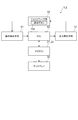
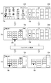
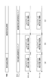
図1〜図4を参照して、第1の実施の形態に係るハプティックジョイスティック装置1について説明する。図1は、本実施の形態に係るハプティックジョイスティック装置の構成図である。図2は、本実施の形態に係る画面遷移時の画面と反力マップの概要を示す一例である。図3は、第1の実施の形態に係る画面遷移時のポインタ及びカーソルがジョイスティック絶対位置と非連動の場合の画面と反力マップの一例である。図4は、図3の例に対応した画面、反力マップ、ポインタ、カーソルのタイミングチャートである。
A
ハプティックジョイスティック装置1は、操作者(運転者、助手席者)によってディスプレイに表示される各種設定画面の複数のボタンに対する選択操作及び決定操作をするための遠隔操作装置であり、カーソル位置(選択されているボタン位置)に基づいてジョイスティックに反力を付加する。特に、ハプティックジョイスティック装置1では、画面遷移時にナビゲーションシステム側で遷移後の設定画面における複数のボタンの中から1つのボタンを選択した場合、画面上のカーソル位置及びポインタ位置とジョイスティックの絶対位置とを非連動とし、そのときのカーソル位置に基づく反力をジョイスティックに付加しない。
The
ハプティックジョイスティック装置1は、決定ボタン10aを有するジョイスティック部10、操作検出手段11、反力発生手段12、ナビECU[Electronic Control Unit]21、ディスプレイ30及びECU40から構成される。
The
なお、本実施の形態ではジョイスティック部10が特許請求の範囲に記載する入力手段及び操作部に相当し、ジョイスティック部10の決定ボタン10aが特許請求の範囲に記載する決定入力部に相当し、反力発生手段12が特許請求の範囲に記載する力付加手段に相当し、ディスプレイ30が特許請求の範囲に記載する表示手段に相当する。
In the present embodiment, the
図2を参照して、ハプティックジョイスティック装置1における設定画面と反力マップについて説明しておく。図2に示す例は、ナビゲーションシステムでの目的地設定画面DSにおいて電話番号ボタンTBが選択操作及び決定操作され、電話番号設定画面TSに遷移した場合を示している。本実施の形態では、設定画面におけるボタンに対する太枠表示でカーソルを示し、設定画面における矢印でポインタを示し、反力マップにおける黒丸で反力マップ上でのジョイスティック位置を示している。カーソルは、設定画面の複数のボタンの中で選択されているボタンを示す。ポインタは、設定画面上でのジョイスティックの位置を示す。
With reference to FIG. 2, the setting screen and reaction force map in the
各種設定画面には、複数のボタンが配置され、各ボタンに対して領域が設定されている。操作者がハプティックジョイスティック装置1のジョイスティック部10を前後左右方向に動かすと(傾倒すると)、そのジョイスティック部10の絶対位置に対応した設定画面上の位置にポインタ(矢印)が表示される。ポインタがあるボタンの設定領域に入ると、そのボタンがカーソル表示(太枠表示)される。ボタンがカーソル表示されているときに、操作者がジョイスティック部10の決定ボタン10aをONすると、そのカーソル表示されているボタンの項目が決定される。そして、次の設定画面又は地図などに画面が遷移する。図2に示す例の場合、操作者がジョイスティック部10によって目的地設定画面DSにおいて電話番号ボタンTBを選択操作したので、電話番号ボタンTBにカーソルが表示されるとともにポインタが表示されている。このときに、操作者が決定ボタン10aをONしたので、目的地設定方法として電話番号が決定され、電話番号設定画面TSに遷移している。
A plurality of buttons are arranged on various setting screens, and an area is set for each button. When the operator moves the
画面遷移すると、ナビゲーションシステムでは、操作性を向上させるために、その遷移後の設定画面の複数のボタンの中から、選択操作頻度の高いボタン又はその画面で前回使用されたボタンを自動的に選択する。その自動で選択されたボタンがカーソル表示されるとともに、そのボタン上にポインタが表示される。この際、カーソル及びポインタは、ジョイスティック部10の絶対位置に対応した位置とはなっていない(非連動)。この自動でボタンが選択されてカーソル表示されているときに、操作者がジョイスティック部10の決定ボタン10aをONすると、そのカーソル表示されているボタンの項目が決定される。この場合、操作者は、選択操作無しに、1つのボタンの項目を決定することができる。図2に示す例の場合、電話番号設定画面TSに遷移すると、電話番号の0〜9のボタンの中から一番目に最も選択される頻度の高い0が自動的に選択され、0ボタン0Bにカーソルが表示されるとともにポインタが表示される。このとき、操作者が決定ボタン10aをONすると(ジョイスティック操作)、電話番号の最初の番号として0が決定される。次に、操作者が7ボタン7Bにポインタが移動するようにジョイスティック部10を動かすと、7ボタン7Bにカーソルが表示されるとともにポインタが表示される。
When the screen transitions, the navigation system automatically selects the button with the highest selection frequency or the last used button on the screen from the multiple buttons on the setting screen after the transition in order to improve operability. To do. The automatically selected button is displayed as a cursor, and a pointer is displayed on the button. At this time, the cursor and the pointer are not positioned corresponding to the absolute position of the joystick unit 10 (not linked). When the button is automatically selected and the cursor is displayed, when the operator turns on the
反力マップは、設定画面毎に設けられ、設定画面の複数のボタンの設定領域に応じて反力発生領域が設定されている。通常、操作者がジョイスティック部10を前後左右方向に動かすと、ハプティックジョイスティック装置1では、ディスプレイ30に表示されている設定画面に対応した反力マップを用いて、そのジョイスティック部10の絶対位置に対応した反力マップ上の位置に基づいて反力を発生させる。ジョイスティック部10の絶対位置に対応した反力マップ上のジョイスティックの位置が反力マップのあるボタンの反力発生領域内にある場合、そのボタンの方向に引き込むような反力が発生され、その反力がジョイスティック部10に付加される。このようにボタンに引き込むような反力をジョイスティック部10に付加することにより、操作者はボタンを選択したことを感じるようなクリック感を受ける。図2(b)に示す例の場合、電話番号設定画面TSに遷移直後は目的地設定画面DSに対応した目的地設定画面用反力マップDMを用いており、ジョイスティック部10の絶対位置に対応した目的地設定画面用反力マップDM上のジョイスティックの位置が電話番号ボタンTB’の反力発生領域内にある。つまり、目的地設定画面DSの電話番号ボタンの中心位置に引き込むような反力がジョイスティック部10に付加されている。
The reaction force map is provided for each setting screen, and reaction force generation regions are set according to the setting regions of a plurality of buttons on the setting screen. Normally, when the operator moves the
画面遷移した場合、ナビゲーションシステムにおいて遷移後の設定画面の複数のボタンの中から1つのボタンが自動的に選択されているが、操作者はジョイスティック部10を遷移前の絶対位置から動かしていないので、操作者の操作に関係のない反力を発生させない。そのために、ハプティックジョイスティック装置1では、ディスプレイ30に表示されている遷移後の設定画面に対応した反力マップに切り替えずに、遷移前の設定画面に対応した反力マップを保持している。したがって、ハプティックジョイスティック装置1では、その遷移前の設定画面に対応した反力マップに基づいて、ジョイスティック部10の絶対位置に対応した遷移前の反力マップ上の位置に基づいて反力を発生させる。その後、この自動でボタンが選択されてカーソル表示されているときに、操作者がジョイスティック部10を操作すると、ハプティックジョイスティック装置1では、ディスプレイ30に表示されている遷移後の設定画面に対応した反力マップに切り替え、遷移後の設定画面に対応した反力マップに基づいて、操作者がジョイスティック部10を前後左右方向に動かしたジョイスティック部10の絶対位置に対応した反力マップ上の位置に基づいて反力を発生させる。図2(b)に示す例の場合、電話番号設定画面TSに遷移しても、目的地設定画面用反力マップDMが保持され、ジョイスティック部10の絶対位置に対応した目的地設定画面用反力マップDM上のジョイスティックの位置が電話番号ボタンTB’の反力発生領域にあるので、その電話番号ボタンの中心位置に引き込むような反力がジョイスティック部10に付加され続ける。次に、操作者が7ボタン7Bにポインタが移動するようにジョイスティック部10を動かすと、電話番号設定画面用反力マップTMに切り替えられ、ジョイスティック部10の絶対位置に対応した電話番号設定画面用反力マップTM上のジョイスティックの位置が7ボタン7B’の反力発生領域内に移動するので、その7ボタンの中心位置に引き込むような反力がジョイスティック部10に付加されている(図2(c))。
When the screen transitions, one button is automatically selected from the plurality of buttons on the setting screen after transition in the navigation system, but the operator does not move the
それでは、ハプティックジョイスティック装置1の各部について説明する。
Now, each part of the
ジョイスティック部10は、遠隔操作でディスプレイ30に表示される画面上のポインタの位置を動かしながらボタンを選択するための操作手段であり、さらに、選択されているボタン(カーソル表示されているボタン)を決定するための操作手段である。ジョイスティック部10のレバーは、X軸(車両前後方向)回りに回動可能かつY軸(車両左右方向)回りに回動可能に、基部が車両側に取り付けられている。そして、ジョイスティック部10では、X軸回りの傾倒角度と画面の左右方向の位置とが対応し、Y軸回りの傾倒角度と画面の上下方向の位置とが対応し、X軸回りの傾倒角度とY軸回りの傾倒角度によって画面上の位置が一意に決まる。したがって、操作者によってジョイスティック部10が所定の方向に傾倒操作されると、そのX軸回りの傾倒角度及びY軸回りの傾倒方向に応じて画面上のポインタが移動し、画面のあるボタンの設定領域内にポインタが位置するとそのボタンがカーソル表示される。
The
決定ボタン10aは、ジョイスティック部10の所定の位置(例えば、先端位置)に取り付けられる。決定ボタン10aは、ON/OFFスイッチであり、例えば、プッシュ式のスイッチである。操作者によって決定ボタン10aがON操作されると、画面上でカーソル表示されているボタンの項目が決定される。
The
操作検出手段11は、ジョイスティック部10の操作状態を検出する手段である。操作検出手段11では、ジョイスティック部10のX軸回りの傾倒角度を検出する。また、操作検出手段11では、ジョイスティック部10のY軸回りの傾倒角度を検出する。また、操作検出手段11では、決定ボタン10aのON/OFFを検出する。そして、操作検出手段11では、それらの検出した情報を操作検出信号としてECU40に送信する。
The
反力発生手段12は、ジョイスティック部10の絶対位置に対応した反力マップ上のジョイスティクの位置に基づいて反力を発生させ、その反力をジョイスティック部10に付加する手段である。反力発生手段12は、ジョイスティック部10に対してX軸回りの反力を発生させるアクチュエータとY軸回りの反力を発生させるアクチュエータを備えている。X軸回りのアクチュエータでは、ECU40からX軸駆動信号を受信すると、そのX軸駆動信号に応じて駆動し、X軸回りの所定のトルクを発生させる。Y軸回りのアクチュエータでは、ECU40からY軸駆動信号を受信すると、そのY軸駆動信号に応じて駆動し、Y軸回りの所定のトルクを発生させる。
The reaction
ナビECU21は、ナビゲーションシステム用のECUであり、自車両の現在位置や走行方向の検出及び目的地までの経路案内制御などを行う。特に、ナビECU21では、操作者による各種設定を行う場合、複数のボタンを配置させた各設定画面のディスプレイ30に表示するための画像を生成する。この画像を生成する際に、ECU40からジョイスティック情報信号を受信すると、ナビECU21では、ジョイスティック情報信号に含まれるジョイスティックの絶対位置に応じた画面上の位置を算出し、設定画面画像においてその算出した位置にポインタ表示するための画像を加える。また、ナビECU21では、ジョイスティックの絶対位置に応じた画面上の位置が設定画面の複数のボタンの各設定領域内に入っているか否かを判定し、あるボタンの設定領域内に入っている場合には設定画面画像においてそのボタンをカーソル表示するための画像を加える。そして、ナビECU21では、その生成した設定画面画像を画像信号としてディスプレイ30に送信する。
The navigation ECU 21 is an ECU for the navigation system, and performs detection of the current position and traveling direction of the host vehicle, route guidance control to the destination, and the like. In particular, the navigation ECU 21 generates an image to be displayed on the
図3に示す例の場合、図3(a)では目的地設定画面DSがディスプレイ30に表示され、目的地設定画面DSの電話番号ボタンTBにカーソルが表示されるとともに、電話番号ボタンTB内にポインタが表示されている。この場合、図4に示すように、カーソルの表示位置及びポインタの表示位置は、ジョイスティック部10の絶対位置に連動している。
In the example shown in FIG. 3, in FIG. 3A, the destination setting screen DS is displayed on the
また、設定画面のあるボタンをカーソル表示している場合にECU40からジョイスティック情報信号を受信すると、ナビECU21では、ジョイスティック情報信号に含まれる決定ボタン10aのON/OFF情報に基づいてONの場合にはそのカーソル表示されているボタンの項目を決定し、設定画面を次の画面に遷移するか否かを判定する。ある設定画面に遷移する場合、ナビECU21では、遷移する設定画面の複数のボタンの中から、その設定画面において一番目に最も選択される可能性の高いボタンを自動的に選択する。そして、ナビECU21では、その遷移する設定画面のディスプレイ30に表示するための画像を生成する。この画像を生成する際、ナビECU21では、設定画面画像においてその自動選択したボタンをカーソル表示するための画像を加えるとともに、その自動選択したボタンの中心位置にポインタを表示するための画像を加える。そして、ナビECU21では、その生成した設定画面画像を画像信号としてディスプレイ30に送信する。その後、ナビECU21では、上記と同様に、ECU40からのジョイスティック情報信号に基づいてカーソル表示及びポインタ表示させるための設定画面画像を生成する。
Further, when a joystick information signal is received from the
図3に示す例の場合、図3(b)では目的地設定画面DSから電話番号設定画面TSに画面遷移し、画面遷移したときに電話番号設定画面TSにおいて一番目に最も選択される可能性の高いボタンとして0ボタンが自動選択されるので、電話番号設定画面TSの0ボタン0Bにカーソルが表示されるとともに、0ボタン0B内にポインタが表示されている。この場合、図4に示すように、カーソルの表示位置及びポインタの表示位置は、ジョイスティック部10の絶対位置に非連動となる。0ボタン0Bにカーソル表示されているときに決定ボタン10aがONされた後に、ジョイスティック部10が7ボタンの方向に動かされたので、電話番号設定画面TSの7ボタン7Bにカーソルが表示されるとともに、7ボタン7B内にポインタが表示されている(図3(c))。この場合、図4(c)に示すように、カーソルの表示位置及びポインタの表示位置は、再び、ジョイスティック部10の絶対位置に連動している。
In the case of the example shown in FIG. 3, the screen transition from the destination setting screen DS to the telephone number setting screen TS in FIG. Since the 0 button is automatically selected as a high button, a cursor is displayed on the 0 button 0B on the telephone number setting screen TS, and a pointer is displayed on the 0 button 0B. In this case, as shown in FIG. 4, the display position of the cursor and the display position of the pointer are not linked to the absolute position of the
また、ナビECU21では、設定画面を遷移する毎に、その設定画面の複数のボタンに対応した反力発生領域を設定した反力マップを生成する。そして、ナビECU21では、その反力マップを反力マップ信号としてECU40に送信する。
The navigation ECU 21 generates a reaction force map in which reaction force generation areas corresponding to a plurality of buttons on the setting screen are set each time the setting screen is changed. Then, the navigation ECU 21 transmits the reaction force map to the
ディスプレイ30は、車載の各種システムで共用されるディスプレイである。ディスプレイ30では、ナビECU21からの画像信号を受信すると、その画像信号に示される画像を画面表示する。
The
ECU40は、CPU[Central Processing Unit]、ROM[ReadOnly Memory]、RAM[Random Access Memory]などからなり、ハプティックジョイスティック装置1を統括制御する電子制御ユニットである。ECU40では、一定時間毎に操作検出手段11から操作検出信号を受信するとともに、設定画面が遷移される毎にナビECU21から反力マップ信号を受信する。そして、ECU40では、これら各信号に基づいて各処理を行い、ジョイスティック情報信号をナビECU21に送信するとともに各駆動信号を反力発生手段12に送信する。
The
具体的には、ECU40では、操作検出信号を受信すると、操作検出信号に含まれるX軸回りの傾倒角度及びY軸回りの傾倒角度に基づいてジョイスティック部10の絶対位置を算出し、そのジョイスティック部10の絶対位置を示すジョイスティック情報信号をナビECU21に送信する。また、ECU40では、操作検出信号を受信すると、操作検出信号に含まれるジョイスティック部10の絶対位置情報を示すジョイスティック情報信号をナビECU21に送信する。
Specifically, when receiving the operation detection signal, the
ECU40では、反力マップ信号を受信すると(画面遷移した場合)、画面遷移後にジョイスティック部10の決定ボタン10aがONされたか否かあるいはジョイスティック部10の絶対位置が移動したか否かを判定する。画面遷移後に決定ボタン10aがONされていないかつジョイスティック部10の絶対位置が移動していない場合、ECU40では、画面遷移前の反力マップを保持する。一方、画面遷移後にジョイスティック部10の絶対位置が移動した場合、ECU40では、反力マップ信号に示される画面遷移後の反力マップに切り替える。
When the reaction force map signal is received (when the screen transitions), the
図3及び図4に示す例の場合、目的地設定画面DSから電話番号設定画面TSに遷移するときに、ナビECU21から反力マップ信号で電話番号設定画面用反力マップTMが送信されるが、0ボタン0Bにカーソル表示されているときにジョイスティック部10の絶対位置が移動するまで、目的地設定画面用反力マップDMが保持される。ジョイスティック部10の絶対位置が移動すると、目的地設定画面用反力マップDMから電話番号設定画面用反力マップTMに切り替えられる。
In the case of the example shown in FIGS. 3 and 4, the phone number setting screen reaction force map TM is transmitted from the navigation ECU 21 as a reaction force map signal when the destination setting screen DS transits to the phone number setting screen TS. The destination setting screen reaction force map DM is held until the absolute position of the
ECU40では、ジョイスティックの絶対位置を算出する毎に、反力マップ上でそのジョイスティックの絶対位置に対応する位置を移動させる。そして、ECU40では、その反力マップ上のジョイスティックの位置が各ボタンの反力発生領域内に入っているか否かを判定し、あるボタンの反力発生領域内に入っている場合にはそのボタンに引き込むような反力を発生させるためのX軸駆動信号及びY軸駆動信号を生成し、そのX軸駆動信号及びY軸駆動信号を反力発生手段12に送信する。
Each time the
図3に示す例の場合、目的地設定画面DSの電話番号ボタンTBにカーソル表示されている場合(図3(a))、目的地設定画面用反力マップDMの電話番号ボタンTB’の反力発生領域内にジョイスティックの位置が入っているので、電話番号ボタンに引き込むような反力を発生さるためのX軸駆動信号及びY軸駆動信号が生成され、ジョイスティック部10に電話番号ボタンに引き込むような反力が付加される。また、画面遷移時(図3(b))に、電話番号設定画面TSの0ボタン0Bにカーソル表示されるが、目的地設定画面用反力マップDMが保持され、電話番号ボタンTB’の反力発生領域内にジョイスティックの位置が入っているので、画面遷移前の電話番号ボタンに引き込むような反力が継続される。また、ジョイスティック部10を操作して電話番号設定画面TSの7ボタン7Bにカーソル表示されている場合(図3(c))、電話番号設定画面用反力マップTMに切り替わっており、7ボタン7B’の反力発生領域内にジョイスティックの位置が入っているので、7ボタンに引き込むような反力を発生さるためのX軸駆動信号及びY軸駆動信号が生成され、ジョイスティック部10に7ボタンに引き込むような反力が付加される。
In the case of the example shown in FIG. 3, when the cursor is displayed on the telephone number button TB on the destination setting screen DS (FIG. 3A), the counter of the telephone number button TB ′ on the reaction force map DM for the destination setting screen is displayed. Since the position of the joystick is within the force generation area, an X-axis drive signal and a Y-axis drive signal for generating a reaction force that is pulled into the telephone number button are generated and pulled into the
図1及び図3を参照して、第1の実施の形態に係るハプティックジョイスティック装置1の動作について説明する。ここでは、図3に示す例で説明する。
With reference to FIG.1 and FIG.3, operation | movement of the
目的地を設定するために、ディスプレイ30に目的地設定画面DSが表示されている場合、操作者が電話番号ボタンを選択するためにジョイスティック部10を動かす。操作検出手段11では、そのジョイスティック部10のX軸回りの傾倒角度及びY軸回りの傾倒角度を検出し、その検出情報を操作検出信号としてECU40に送信する。この操作検出信号を受信すると、ECU40では、X軸回りの傾倒角度及びY軸回りの傾倒角度に基づいてジョイスティック部10の絶対位置を算出し、そのジョイスティック部10の絶対位置を示すジョイスティック情報信号をナビECU21に送信する。
When the destination setting screen DS is displayed on the
このジョイスティック情報信号を受信すると、ナビECU21では、ジョイスティックの絶対位置に応じて画面上の位置を算出し、目的地設定画面DS内の電話番号ボタンTB内にポインタを表示しかつ目的地設定画面DSの電話番号ボタンTBにカーソルを表示する目的地設定画面画像を画像信号としてディスプレイ30に送信する。この画像信号を受信すると、ディスプレイ30では、電話番号ボタンTB内でポインタ表示するとともに電話番号ボタンTBをカーソル表示した目的地設定画面DSを表示する。
Upon receiving this joystick information signal, the navigation ECU 21 calculates a position on the screen according to the absolute position of the joystick, displays a pointer in the telephone number button TB in the destination setting screen DS, and displays the destination setting screen DS. A destination setting screen image for displaying a cursor on the telephone number button TB is transmitted to the
また、ECU40では、そのジョイスティックの絶対位置に対応する位置が目的地設定画面用反力マップDSの各ボタンの反力発生領域内に入っているか否かを判定し、電話番号ボタンTB’の反力発生領域内に入っているので、電話番号ボタンに引き込むような反力を発生させるためのX軸駆動信号及びY軸駆動信号を反力発生手段12に送信する。このX軸駆動信号及びY軸駆動信号を受信すると、反力発生手段12では、そのX軸駆動信号に応じて駆動してX軸回りの所定のトルクを発生させるとともに、そのY軸駆動信号に応じて駆動してY軸回りの所定のトルクを発生させる。すると、ジョイスティック部10には、電話番号ボタンに引き込むような反力が付加される。
Further, the
目的地設定画面DSの電話番号ボタンTBにカーソル表示されているときに、操作者が電話番号ボタンを決定するために決定ボタン10aをONする。操作検出手段11では、その決定ボタン10aのONを検出し、その検出情報を操作検出信号としてECU40に送信する。この操作検出信号を受信すると、ECU40では、そのON情報を示すジョイスティック情報信号をナビECU21に送信する。
When the cursor is displayed on the telephone number button TB on the destination setting screen DS, the operator turns on the
このジョイスティック情報信号を受信すると、ナビECU21では、決定ボタン10aのON情報に基づいてカーソル表示されている電話番号による目的地設定を決定し、電話番号設定画面TSに遷移すると判定する。そして、ナビECU21では、電話番号設定画面TSの0〜9のボタンの中から0ボタンを自動的に選択し、電話番号設定画面TSの0ボタン0Bの中心位置にポインタを表示しかつ0ボタン0Bにカーソルを表示する電話番号設定画面画像を画像信号としてディスプレイ30に送信する。この画像信号を受信すると、ディスプレイ30では、0ボタン0B内でポインタ表示するとともに0ボタン0Bをカーソル表示した電話番号設定画面TSを表示する。また、ナビECU21では、電話番号設定画面用反力マップTMを含む反力マップ信号をECU40に送信する。
When this joystick information signal is received, the navigation ECU 21 determines the destination setting based on the telephone number displayed by the cursor based on the ON information of the
この反力マップ信号を受信すると、ナビECU21では、電話番号設定画面遷移後にジョイスティック部10の絶対位置が移動したか否か判定する。ジョイスティック部10の絶対位置が移動していないと判定した場合、ECU40では、画面遷移前の目的地設定画面用反力マップDMを保持し、上記と同様に電話番号ボタンに引き込むような反力を発生させるためのX軸駆動信号及びY軸駆動信号を反力発生手段12に送信する。これによって、ジョイスティック部10には、電話番号ボタンに引き込むような反力が付加され続ける。
When this reaction force map signal is received, the navigation ECU 21 determines whether or not the absolute position of the
電話番号設定画面TSの0ボタン0Bにカーソル表示されているときに、操作者が0ボタンを決定するために決定ボタン10aをONする。操作検出手段11では、その決定ボタン10aのONを検出し、その検出情報を操作検出信号としてECU40に送信する。この操作検出信号を受信すると、ECU40では、そのON情報を示すジョイスティック情報信号をナビECU21に送信する。
When the cursor is displayed on the 0 button 0B of the telephone number setting screen TS, the operator turns on the
このジョイスティック情報信号を受信すると、ナビECU21では、決定ボタン10aのON情報に基づいてカーソル表示されている0を一番目の電話番号として決定する。
When this joystick information signal is received, the navigation ECU 21 determines 0 as the first telephone number based on the ON information of the
次の電話番号を入力するために、操作者が電話番号設定画面TSの7ボタンを選択するためにジョイスティック部10を動かす。操作検出手段11では、そのジョイスティック部10のX軸回りの傾倒角度及びY軸回りの傾倒角度を検出し、その検出情報を操作検出信号としてECU40に送信する。この操作検出信号を受信すると、ECU40では、X軸回りの傾倒角度及びY軸回りの傾倒角度に基づいてジョイスティック部10の絶対位置を算出し、そのジョイスティック部10の絶対位置を示すジョイスティック情報信号をナビECU21に送信する。また、ECU40では、ジョイスティック部10の絶対位置が移動したと判定した場合、目的地設定画面用反力マップDMから電話番号設定用反力マップTMに切り替える。
In order to input the next telephone number, the operator moves the
このジョイスティック情報信号を受信すると、ナビECU21では、ジョイスティックの絶対位置に応じて画面上の位置を算出し、電話番号設定画面TSの7ボタン7B内にポインタを表示しかつ電話番号設定画面TSの7ボタン7Bにカーソルを表示する電話番号設定画面画像を画像信号としてディスプレイ30に送信する。この画像信号を受信すると、ディスプレイ30では、7ボタン7B内でポインタ表示するとともに7ボタン7Bをカーソル表示した電話番号設定画面TSを表示する。
When this joystick information signal is received, the navigation ECU 21 calculates the position on the screen according to the absolute position of the joystick, displays a pointer in the 7
また、ECU40では、そのジョイスティックの絶対位置に対応する位置が電話番号設定画面用反力マップTMの各ボタンの反力発生領域内に入っているか否かを判定し、7ボタン7B’の反力発生領域内に入っていると判定し、7ボタンに引き込むような反力を発生させるためのX軸駆動信号及びY軸駆動信号を反力発生手段12に送信する。このX軸駆動信号及びY軸駆動信号を受信すると、反力発生手段12では、そのX軸駆動信号に応じて駆動してX軸回りの所定のトルクを発生させるとともに、そのY軸駆動信号に応じて駆動してY軸回りの所定のトルクを発生させる。すると、ジョイスティック部10には、7ボタンに引き込むような反力が付加される。
Further, the
このハプティックジョイスティック装置1によれば、ナビゲーションシステムにおいて画面遷移し、遷移後の設定画面で自動的にボタンを選択した場合、操作者によってジョイスティック操作されるまで遷移前の反力マップを保持するので、ジョイスティック部10には自動選択されたボタン位置(カーソル表示されているボタン位置)に対応した反力が付加されない。そのため、操作者が動かしていないにもかかわらず、ジョイスティック部10が勝手に動くようなことがなく、操作者が違和感を受けず、煩わしさを感じない。
According to the
また、ハプティックジョイスティック装置1によれば、ナビゲーションシステムにおいて画面遷移し、遷移後の設定画面で自動的にボタンを選択した場合、画面上のカーソル及びポインタをジョイスティック部10の絶対位置に非連動とし、自動的に選択したボタンに対応してカーソル表示及びポインタ表示を行うので、操作者がどのボタンが選択されているかを認識できる。その際、操作者は決定ボタン10aへのON操作だけでボタンを決定できるので、操作性も向上する。例えば、全ての段階(画面遷移、電話番号入力など)で次の項目ボタンを自動選択するようにした場合、自動選択された項目が適当であれば、決定ボタン10aのON操作のみで操作入力が完了し、その間ジョイスティック部10は動かないため、煩わしさを軽減できる。
Further, according to the
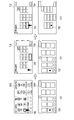
図1及び図5、図6を参照して、第2の実施の形態に係るハプティックジョイスティック装置2について説明する。図5は、第2の実施の形態に係る画面遷移時のカーソルのみがジョイスティック絶対位置と非連動の場合の画面と反力マップの一例である。図6は、図5の例に対応した画面、反力マップ、ポインタ、カーソルのタイミングチャートである。なお、ハプティックジョイスティック装置2では、第1の実施の形態に係るハプティックジョイスティック装置1と同様の構成については同一の符号を付し、その説明を省略する。
A
ハプティックジョイスティック装置2は、第1の実施の形態に係るハプティックジョイスティック装置1と比較すると、画面遷移時にナビゲーションシステムによって遷移後の設定画面における複数のボタンの中から1つのボタンを選択した場合、画面上のカーソル位置だけジョイスティック絶対位置と非連動とした点だけが異なる。そこで、その点のみ詳細に説明する。
Compared with the
ハプティックジョイスティック装置2は、決定ボタン10aを有するジョイスティック部10、操作検出手段11、反力発生手段12、ナビECU22、ディスプレイ30及びECU40から構成される。第2の実施の形態では、ナビECU22における第1の実施の形態と異なる処理についてのみ詳細に説明する。
The
ナビECU22では、画面遷移する場合に遷移する設定画面の複数のボタンの中からボタンを1つ自動的に選択すると、その遷移後の複数のボタンを配置させた設定画面のディスプレイ30に表示するための画像を生成する。この画像を生成する際、ナビECU22では、ECU40からのジョイスティック情報信号に含まれるジョイスティックの絶対位置に応じた画面上の位置を算出し、設定画面画像においてその算出した位置にポインタを表示するための画像を加える。また、ナビECU22では、設定画面画像においてその自動選択したボタンをカーソル表示するための画像を加える。そして、ナビECU22では、その生成した設定画面画像を画像信号としてディスプレイ30に送信する。
In the navigation ECU 22, when one button is automatically selected from a plurality of buttons on the setting screen that changes when the screen changes, the navigation ECU 22 displays the button on the
図5に示す例の場合、図5(b)のように目的地設定画面DSから電話番号設定画面TSに画面遷移し、画面遷移したときに電話番号設定画面TSにおいて0ボタンが自動的に選択されるので、電話番号設定画面TSの0ボタン0Bにカーソルが表示されるとともに、ジョイスティック部10の絶対位置に応じた位置(目的地設定画面DSの電話番号ボタンTB内の位置が保持される)にポインタが表示されている。この場合、図6(b)に示すように、カーソルの表示位置は、ジョイスティック部10の絶対位置に非連動となる。しかし、ポインタの表示位置は、ジョイスティック部10の絶対位置に連動している。0ボタン0Bにカーソル表示されているときに決定ボタン10aがONされた後に、ジョイスティック部10が7ボタンの方向に動かされたので、電話番号設定画面TSの7ボタン7Bにカーソルが表示されるとともに、7ボタン7B内にポインタが表示されている。この場合、図6(c)に示すように、カーソルの表示位置は、再び、ジョイスティック部10の絶対位置に連動する。
In the case of the example shown in FIG. 5, the screen changes from the destination setting screen DS to the telephone number setting screen TS as shown in FIG. 5B, and the 0 button is automatically selected on the telephone number setting screen TS when the screen changes. Therefore, a cursor is displayed on the 0 button 0B on the telephone number setting screen TS, and a position corresponding to the absolute position of the joystick unit 10 (a position in the telephone number button TB on the destination setting screen DS is held). The pointer is displayed at. In this case, as shown in FIG. 6B, the cursor display position is not linked to the absolute position of the
図1及び図5を参照して、第2の実施の形態に係るハプティックジョイスティック装置2の動作について説明する。ここでは、図5に示す例で説明し、第1の実施の形態で説明した動作と異なる点だけ詳細に説明する。
With reference to FIG.1 and FIG.5, operation | movement of the
目的地設定画面DSの電話番号ボタンTBにカーソル表示されている場合、操作者が電話番号ボタンを決定するために決定ボタン10aをONする。操作検出手段11では、その決定ボタン10aのONを検出し、その検出情報を操作検出信号としてECU40に送信する。この操作検出信号を受信すると、ECU40では、そのON情報を示すジョイスティック情報信号をナビECU22に送信する。
When the cursor is displayed on the telephone number button TB on the destination setting screen DS, the operator turns on the
このジョイスティック情報信号を受信すると、ナビECU22では、決定ボタン10aのON情報に基づいてカーソル表示されている電話番号による目的地設定を決定し、電話番号設定画面TSに遷移すると判定する。そして、ナビECU22では、電話番号設定画面TSの0〜9のボタンの中から0ボタンを自動的に選択し、電話番号設定画面TS上でジョイスティック部10の絶対位置に対応した位置にポインタを表示しかつ0ボタン0Bにカーソルを表示する電話番号設定画面画像を画像信号としてディスプレイ30に送信する。この画像信号を受信すると、ディスプレイ30では、ジョイスティック部10の現在の絶対位置に対応した位置でポインタ表示するとともに0ボタン0Bをカーソル表示した電話番号設定画面TSを表示する。
When this joystick information signal is received, the navigation ECU 22 determines the destination setting based on the telephone number displayed by the cursor based on the ON information of the
このハプティックジョイスティック装置2によれば、第1の実施の形態に係るハプティックジョイスティック装置1と同様の効果を有する。また、ハプティックジョイスティック装置2によれば、ナビゲーションシステムにおいて画面遷移し、遷移後の設定画面で自動的にボタンを選択した場合、画面上のカーソルだけをジョイスティック部10の絶対位置に非連動とし、自動的にボタンを選択した位置に対応してカーソル表示し、ジョイスティック部10の絶対位置に対応した位置でポインタ表示を行うので、操作者がジョイスティック部10の実際の位置を認識できるとともにどのボタンが選択されているかを認識できる。
The
以上、本発明に係る実施の形態について説明したが、本発明は上記実施の形態に限定されることなく様々な形態で実施される。 As mentioned above, although embodiment which concerns on this invention was described, this invention is implemented in various forms, without being limited to the said embodiment.
例えば、本実施の形態では入力装置として車両に搭載されるハプティックジョイスティック装置に適用したが、車両以外で用いられる入力装置にも適用可能であり、ジョイスティック以外にもトラックボールなどの他の遠隔ハプティックデバイスにも適用可能である。 For example, in this embodiment, the present invention is applied to a haptic joystick device mounted on a vehicle as an input device. However, the present invention can also be applied to an input device used other than a vehicle. It is also applicable to.
また、本実施の形態ではナビゲーションシステムの設定画面に適用したが、遠隔操作可能な様々な画面(例えば、エアコンの設定画面、オーディオの設定画面)に対する入力に適用可能である。 Further, although the present embodiment is applied to the setting screen of the navigation system, it can be applied to input to various screens that can be remotely operated (for example, an air conditioner setting screen and an audio setting screen).
また、本実施の形態ではジョイスティックに付加する力として選択されたボタンの中心位置に引き込むような力を付加する構成としたが、選択されたボタンの位置に基づいて操作者の操作方向とは逆方向の力を付加するなどの様々な力(操作者に触覚感を与えるような力)を付加してよい。 In this embodiment, the force applied to the center position of the selected button is applied as the force applied to the joystick. However, the operation direction is opposite to the operation direction of the operator based on the position of the selected button. Various forces (such as a force that gives a tactile sensation to the operator) such as a directional force may be added.
また、本実施の形態では画面遷移時に遷移した画面上の最初のボタンだけを装置側で自動的に選択する構成としたが、同一の画面上で複数のボタンを自動的に選択する構成としてもよく、その場合には自動で複数のボタンを選択している間はその各ボタン位置に対応した力をジョイスティックに付加しない。例えば、電話番号選択画面の場合には最も操作頻度の高い市外局番あるいは電話番号に従って複数のボタンを順次自動選択する。 In the present embodiment, the device automatically selects only the first button on the screen that has transitioned at the time of screen transition. However, the configuration may be such that a plurality of buttons are automatically selected on the same screen. In that case, the force corresponding to each button position is not applied to the joystick while a plurality of buttons are automatically selected. For example, in the case of a telephone number selection screen, a plurality of buttons are sequentially automatically selected in accordance with the area code or telephone number that is most frequently operated.
また、本実施の形態では各ボタンが選択された状態をカーソル表示で表わしたが、反転表示、他色表示などの他の表示方法でもよい。 In the present embodiment, the state in which each button is selected is represented by a cursor display, but other display methods such as reverse display and other color display may be used.
また、本実施の形態ではジョイスティックの絶対位置が移動した場合に反力マップを切り替えたが、ジョイスティックの傾倒操作や決定ボタンのONを検出した場合に反力マップを切り替えるようにしてもよい。 In the present embodiment, the reaction force map is switched when the absolute position of the joystick is moved. However, the reaction force map may be switched when a tilting operation of the joystick or ON of the determination button is detected.
1,2…ハプティックジョイスティック装置、10…ジョイスティック部、10a…決定ボタン、11…操作検出手段、12…反力発生手段、21,22…ナビECU、30…ディスプレイ、40…ECU
DESCRIPTION OF
Claims (4)
前記力付加手段は、前記表示手段の画面上の複数の選択可能部分に応じて反力発生領域が設定されている反力マップを有し、前記操作部の絶対位置に対応した反力マップ上の位置が反力マップの任意の選択可能部分に応じた反力発生領域内にある場合に当該任意の選択可能部分の中心位置に引き込む反力を前記操作部に付加し、
前記操作部への操作状態に関係なく、所定の選択順に基づいて前記表示手段の画面上の複数の選択可能部分のうちのいずれか1つ以上の選択可能部分を自動選択した場合に当該自動選択した選択可能部分を選択状態にするとともに前記操作部の絶対位置に対応した反力マップ上の位置を当該自動選択する前の状態で保持することによって当該自動選択した選択可能部分の中心位置に引き込む反力を前記操作部に付加しないことを特徴とする入力装置。 Display means for displaying a plurality of selectable parts on the screen, input means having an operation unit for the operator to select from a plurality of selectable parts on the screen of the display means, and on the screen of the display means One of a plurality of selectable portions on the screen of the display unit according to a selection operation by the operator by the operation unit is provided. The force adding unit applies a force to the operation unit corresponding to the selection position. An input device that places a selectable portion in a selected state and applies a force corresponding to the position of the selected selectable portion to the operation unit by the force adding means,
The force adding means has a reaction force map in which reaction force generation areas are set according to a plurality of selectable portions on the screen of the display means, and is on a reaction force map corresponding to the absolute position of the operation unit. Is added to the operation portion a reaction force that is drawn to the center position of the arbitrary selectable portion when the position is within the reaction force generation region according to the arbitrary selectable portion of the reaction force map,
Regardless of the operation state of the operation unit, when one or more selectable parts on the screen of the display means are automatically selected based on a predetermined selection order, the automatic selection is performed. The selected portion is placed in the selected state, and the position on the reaction force map corresponding to the absolute position of the operation unit is held in the state before the automatic selection, thereby pulling it into the center position of the automatically selected selectable portion. An input device characterized in that a reaction force is not added to the operation unit.
Priority Applications (1)
| Application Number | Priority Date | Filing Date | Title |
|---|---|---|---|
| JP2008321092A JP5233644B2 (en) | 2008-12-17 | 2008-12-17 | Input device |
Applications Claiming Priority (1)
| Application Number | Priority Date | Filing Date | Title |
|---|---|---|---|
| JP2008321092A JP5233644B2 (en) | 2008-12-17 | 2008-12-17 | Input device |
Publications (2)
| Publication Number | Publication Date |
|---|---|
| JP2010146170A JP2010146170A (en) | 2010-07-01 |
| JP5233644B2 true JP5233644B2 (en) | 2013-07-10 |
Family
ID=42566571
Family Applications (1)
| Application Number | Title | Priority Date | Filing Date |
|---|---|---|---|
| JP2008321092A Expired - Fee Related JP5233644B2 (en) | 2008-12-17 | 2008-12-17 | Input device |
Country Status (1)
| Country | Link |
|---|---|
| JP (1) | JP5233644B2 (en) |
Families Citing this family (4)
| Publication number | Priority date | Publication date | Assignee | Title |
|---|---|---|---|---|
| JP5263243B2 (en) | 2010-09-02 | 2013-08-14 | 株式会社デンソー | Vehicle display device |
| JP5387556B2 (en) * | 2010-12-24 | 2014-01-15 | 株式会社デンソー | In-vehicle device |
| JP5664323B2 (en) * | 2011-02-21 | 2015-02-04 | 株式会社デンソー | Operation support system, in-vehicle device, and portable terminal |
| JP5924243B2 (en) * | 2012-11-16 | 2016-05-25 | 株式会社デンソー | Operation selection device |
Family Cites Families (6)
| Publication number | Priority date | Publication date | Assignee | Title |
|---|---|---|---|---|
| JP2004272805A (en) * | 2003-03-11 | 2004-09-30 | Nissan Motor Co Ltd | Multi-directional input device |
| JP4148084B2 (en) * | 2003-09-25 | 2008-09-10 | 株式会社デンソー | Display operation system |
| JP4148104B2 (en) * | 2003-10-31 | 2008-09-10 | 株式会社デンソー | Display operation system |
| JP4720258B2 (en) * | 2005-04-05 | 2011-07-13 | ソニー株式会社 | Data processing method, electronic device, and program |
| JP4899627B2 (en) * | 2006-05-15 | 2012-03-21 | トヨタ自動車株式会社 | Vehicle input device |
| JP2008090640A (en) * | 2006-10-03 | 2008-04-17 | Toyota Motor Corp | Input device |
-
2008
- 2008-12-17 JP JP2008321092A patent/JP5233644B2/en not_active Expired - Fee Related
Also Published As
| Publication number | Publication date |
|---|---|
| JP2010146170A (en) | 2010-07-01 |
Similar Documents
| Publication | Publication Date | Title |
|---|---|---|
| US8384666B2 (en) | Input device for operating in-vehicle apparatus | |
| US8032280B2 (en) | Switch control device and switch control method | |
| JP4257549B2 (en) | Operating device | |
| EP2726970B1 (en) | Vehicle operation device and vehicle operation method | |
| JP5187179B2 (en) | Vehicle periphery monitoring device | |
| JP5177120B2 (en) | Display control device for remote operation device | |
| US20070182721A1 (en) | Display Device, User Interface, and Method for Providing Menus | |
| JP6555348B2 (en) | Image display control device | |
| US8355838B2 (en) | Vehicular input device and method for controlling the same | |
| WO2010043944A1 (en) | Parking assistance apparatus and control method thereof | |
| US9541416B2 (en) | Map display controller | |
| JP2011193040A (en) | Input device for vehicle, and pointer display method | |
| WO2015162895A1 (en) | Image processing device, method for controlling image processing device, program, and display device | |
| JP2014144735A (en) | Display controller | |
| CN106458114A (en) | Operating device for vehicles | |
| JP5233644B2 (en) | Input device | |
| JP6477123B2 (en) | Operation system | |
| JP4840332B2 (en) | Remote control device | |
| CN111806463B (en) | Method and system for exhibiting operation mode switching of a vehicle | |
| JP5234608B2 (en) | Operating parameter setting device and operating parameter setting method | |
| JP2009301082A (en) | Operation sense imparting type input device | |
| JP7622683B2 (en) | Vehicle display system | |
| JP4962387B2 (en) | Pointer display / movement device and program for pointer display / movement device | |
| JP2007226397A (en) | Pointing device, pointing method, pointing program, and recording medium on which pointing program is recorded | |
| JP2007212888A (en) | Display device |
Legal Events
| Date | Code | Title | Description |
|---|---|---|---|
| A621 | Written request for application examination |
Free format text: JAPANESE INTERMEDIATE CODE: A621 Effective date: 20111019 |
|
| A131 | Notification of reasons for refusal |
Free format text: JAPANESE INTERMEDIATE CODE: A131 Effective date: 20120814 |
|
| A977 | Report on retrieval |
Free format text: JAPANESE INTERMEDIATE CODE: A971007 Effective date: 20120815 |
|
| A521 | Request for written amendment filed |
Free format text: JAPANESE INTERMEDIATE CODE: A523 Effective date: 20120920 |
|
| TRDD | Decision of grant or rejection written | ||
| A01 | Written decision to grant a patent or to grant a registration (utility model) |
Free format text: JAPANESE INTERMEDIATE CODE: A01 Effective date: 20130226 |
|
| A61 | First payment of annual fees (during grant procedure) |
Free format text: JAPANESE INTERMEDIATE CODE: A61 Effective date: 20130311 |
|
| FPAY | Renewal fee payment (event date is renewal date of database) |
Free format text: PAYMENT UNTIL: 20160405 Year of fee payment: 3 |
|
| LAPS | Cancellation because of no payment of annual fees |