JP5233284B2 - Cuff supporter and stator manufacturing method using the same - Google Patents
Cuff supporter and stator manufacturing method using the same Download PDFInfo
- Publication number
- JP5233284B2 JP5233284B2 JP2008002483A JP2008002483A JP5233284B2 JP 5233284 B2 JP5233284 B2 JP 5233284B2 JP 2008002483 A JP2008002483 A JP 2008002483A JP 2008002483 A JP2008002483 A JP 2008002483A JP 5233284 B2 JP5233284 B2 JP 5233284B2
- Authority
- JP
- Japan
- Prior art keywords
- cuff
- slot
- supporter
- coil
- stator core
- Prior art date
- Legal status (The legal status is an assumption and is not a legal conclusion. Google has not performed a legal analysis and makes no representation as to the accuracy of the status listed.)
- Expired - Fee Related
Links
- 238000004519 manufacturing process Methods 0.000 title claims description 11
- 238000003780 insertion Methods 0.000 claims description 21
- 230000037431 insertion Effects 0.000 claims description 21
- 230000013011 mating Effects 0.000 claims description 6
- 238000000034 method Methods 0.000 description 22
- 238000003825 pressing Methods 0.000 description 8
- 238000010586 diagram Methods 0.000 description 3
- 230000001154 acute effect Effects 0.000 description 2
- 238000005452 bending Methods 0.000 description 2
- 210000001217 buttock Anatomy 0.000 description 2
- 238000009413 insulation Methods 0.000 description 2
- 238000000465 moulding Methods 0.000 description 2
- 229910000976 Electrical steel Inorganic materials 0.000 description 1
- 229910000831 Steel Inorganic materials 0.000 description 1
- 238000000748 compression moulding Methods 0.000 description 1
- 230000000694 effects Effects 0.000 description 1
- 238000004080 punching Methods 0.000 description 1
- 239000010959 steel Substances 0.000 description 1
Images


Landscapes
- Insulation, Fastening Of Motor, Generator Windings (AREA)
- Manufacture Of Motors, Generators (AREA)
Description
本発明は、ステータコアのスロットに挿入されるスロット紙のカフス部を保護するカフスサポータ及びそのカフスサポータを用いたステータ製造方法に関する。 The present invention relates to a cuff supporter for protecting a cuff portion of slot paper inserted into a slot of a stator core, and a stator manufacturing method using the cuff supporter.
従来、回転電機の製造工程において、ステータコアとそのスロットに挿入されるコイルとを絶縁するために、ステータコアのスロットには、コイルの挿入に先立って、スロットの形状に折り曲げられたスロット紙が挿入される。図19に示すように、スロット紙51には、スロットへの挿入方向の上側及び下側に、スロット紙51を折り曲げてなるカフス部51a,51bが形成される。スロット紙51がスロットに挿入された後は、カフス部51a,51bがステータコアの上下両面に当たることで、スロット紙51のスロットからの抜けを防止するようになっている。
Conventionally, in the manufacturing process of a rotating electrical machine, in order to insulate a stator core from a coil inserted into the slot, slot paper folded into a slot shape is inserted into the slot of the stator core prior to insertion of the coil. The As shown in FIG. 19, the
ここで、スロットにスロット紙51が挿入された後には、スロット紙51のカフス部51a,51bを保護するために、ステータコアにカフスサポータが装着される。カフスサポータは、複数の棒状体が互いに接しながら、ステータコアの上下両端面にて放射状に配置される。例えば、下記の特許文献1には、カフスサポータを用いたステータ製造方法が開示されている。図20に、ステータコアの一つのスロットに対応した一組のカフスサポータ52を平面図により示す。
Here, after the
ところで、特許文献1に記載の技術では、図20に示すように、一つのスロット紙51が、隣接する二本の棒状体53,54の先端部53a,54aにより形成される二股部55にて保護されるようになっている。ここで、二股部55の内側頂部には、隣接する二本の棒状体53,54の合わせ面56の継ぎ目56aが現れ出る。二本の棒状体53,54は、成形精度が全く同じでないことから、図21に示すように、継ぎ目56aに段差ができることがある。このため、スロットにコイルを挿入する工程では、図22に示すように、スロット紙51のカフス部51a,51bがコイル57により継ぎ目56aに押し付けられて破損するおそれがあった。
By the way, in the technique described in
この発明は、上記事情に鑑みてなされたものであって、その目的は、コイルの押し付けによるスロット紙の破損を防止することを可能としたカフスサポータ及びそれを用いたステータ製造方法を提供することにある。 The present invention has been made in view of the above circumstances, and an object thereof is to provide a cuff supporter capable of preventing the slot paper from being damaged by the pressing of the coil, and a stator manufacturing method using the cuff supporter. It is in.
上記目的を達成するために、請求項1に記載の発明は、ステータコアのスロットに挿入されるスロット紙のカフス部を、隣接する二本の棒状体の先端部より形成される二股部にて保護するカフスサポータであって、前記二股部の内側頂部には、前記二本の棒状体の合わせ面の継ぎ目があり、前記二股部の内側の少なくとも前記継ぎ目の近傍に、前記スロット紙の後に前記スロットに挿入されるコイルから前記カフス部を退ける庇部を設け、前記庇部は、前記二股部の内壁がその縁部にて張り出した部分であることを趣旨とする。 In order to achieve the above object, according to the first aspect of the present invention, the cuff portion of the slot paper inserted into the slot of the stator core is protected by the bifurcated portion formed by the tip portions of the two adjacent rod-shaped bodies. A cuff supporter having a seam of a mating surface of the two rod-like bodies at an inner top portion of the bifurcated portion, and at least in the vicinity of the seam inside the bifurcated portion, the slot after the slot paper. only setting the eaves portion to reject the cuff from the coil to be inserted into, the eaves section, the purpose that the inner wall of the bifurcated portion is a protruding portion at its edge.
上記発明の構成によれば、隣接する二本の棒状体の先端部より形成される二股部の内側頂部には、二本の棒状体の合わせ面の継ぎ目があるが、その二股部の内側の少なくとも継ぎ目の近傍に庇部が設けられる。従って、スロット紙の後にスロットにコイルが挿入され
ても、スロット紙のカフス部がこの庇部によりコイルから退けられるので、カフス部がコイルによって継ぎ目に押し付けられることがない。
According to the configuration of the invention described above, the inner top portion of the bifurcated portion formed from the tip portions of the two adjacent rod-shaped bodies has a joint of the mating surfaces of the two rod-shaped bodies. A collar is provided at least near the seam. Therefore, even if the coil is inserted into the slot after the slot paper, the cuff portion of the slot paper is retracted from the coil by the collar portion, so that the cuff portion is not pressed against the seam by the coil.
上記目的を達成するために、請求項2に記載の発明は、請求項1に記載の発明において、庇部は、凸に湾曲した形状をなすことを趣旨とする。
In order to achieve the above object, the invention described in
上記目的を達成するために、請求項3に記載の発明のカフスサポータを用いたステータ製造方法は、ステータコアのスロットに、上下にカフス部を有するスロット紙を、カフス部がステータコアの上下両面から突出するように挿入するスロット紙挿入工程と、ステータコアの上下両面に対し、スロットに挿入されたスロット紙に対応して、請求項1に記載されたカフスサポータを装着するカフスサポータ装着工程と、スロット紙が挿入され、カフスサポータが装着された状態で、カフスサポータの庇部によりスロット紙のカフス部をコイルから退けながらスロットにコイルを挿入するコイル挿入工程とを備えたことを趣旨とする。
In order to achieve the above object, a stator manufacturing method using the cuff supporter according to the third aspect of the present invention is the slot of the stator core, the slot paper having the cuff portions on the top and bottom, and the cuff portions project from both the top and bottom surfaces of the stator core. The slot paper insertion step of inserting the cuff supporter according to
上記発明の構成によれば、スロット紙挿入工程によりスロットにスロット紙が挿入され、カフスサポータ装着工程によりスロットに挿入されたスロット紙に対応して、ステータコアの上下両面に対してカフスサポータが装着された状態では、ステータコアの上下両面から、スロット紙のカフス部が突出し、そのカフス部がカフスサポータの二股部により囲まれた状態となる。その後、コイル挿入工程では、スロット紙が挿入され、カフスサポータが装着された状態で、スロットにコイルが挿入される。このとき、スロット紙のカフス部がコイルにより押圧されるが、カフスサポータの庇部によりカフス部がコイルから退けられるので、コイルによりカフス部が継ぎ目に押し付けられることがない。 According to the configuration of the invention, the slot paper is inserted into the slot by the slot paper insertion process, and the cuff supporters are attached to the upper and lower surfaces of the stator core corresponding to the slot paper inserted into the slot by the cuff supporter attachment process. In this state, the cuff portion of the slot paper protrudes from the upper and lower surfaces of the stator core, and the cuff portion is surrounded by the forked portion of the cuff supporter. Thereafter, in the coil insertion step, the slot paper is inserted, and the coil is inserted into the slot with the cuff supporter attached. At this time, the cuff part of the slot paper is pressed by the coil, but the cuff part is retracted from the coil by the collar part of the cuff supporter, so that the cuff part is not pressed against the seam by the coil.
請求項1乃至2の何れかに記載の発明によれば、コイルの押し付けによるスロット紙の破損を防止することができる。
According to the invention described in any one of
請求項3に記載の発明によれば、スロットの押し付けによるスロット紙の破損を防止することができる。
According to the invention described in
[第1実施形態]
以下、本発明のカフスサポータ及びそれを用いたステータ製造方法を具体化した第1実施形態につき図面を参照して詳細に説明する。
[First Embodiment]
Hereinafter, a cuff supporter of the present invention and a stator manufacturing method using the same will be described in detail with reference to the drawings.
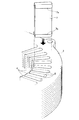
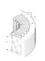
図1に、この実施形態のステータ1を斜視図により示す。図2に、ステータ1を構成するステータコア2を平面図により示す。図3に、ステータコア2を縦断面図により示す。図4に、ステータコア2を斜視図により示す。図1に示すように、この実施形態のステータ1は、ステータコア2と、そのステータコア2に巻き付けられたコイル3とを備える。図2〜図4に示すように、ステータコア2は、平面視リング状をなし、複数のティース4及びスロット5を有する。複数のティース4は、ステータコア2の径方向内側へ向かって伸びる。複数のスロット5は、隣り合うティース4の間にそれぞれ形成される。このステータコア2は、例えば、方向性珪素鋼板をプレス打ち抜きして形成された鋼板6を積み重ね、互いに固着して構成される。
FIG. 1 is a perspective view of a
上記のようなステータ1の製造工程で、ステータコア2の各スロット5には、コイル3が挿入され、そのコイル3の巻き付けが行われる。その過程で、コイル3とステータコア2との絶縁性を保持するために、スロット紙挿入工程では、各スロット5に、コイル3の挿入に先立って絶縁用のスロット紙が挿入される。図5,6には、スロット紙挿入工程を斜視図により示す。図5,6に示すように、スロット紙7には、スロット5への挿入方向の上側及び下側に、スロット紙7を折り曲げてなるカフス部7a,7bがそれぞれ形成される。スロット紙7がスロット5に挿入された後は、カフス部7a,7bがステータコア
2の上面2a及び下面2bに当たることで、スロット紙7がスロット5から抜け止めされる。
In the manufacturing process of the
後工程であるコイル挿入工程では、図7に示すように、スロット紙7の後にスロット5にコイル3が挿入されるが、この実施形態では、スロット5に挿入されたスロット紙7のカフス部7a,7bを保護するために、コイル挿入工程の前にカフスサポータ装着工程が実施され、ステータコア2の上下両面2a,2bに対して上側カフスサポータ及び下側カフスサポータが装着されるようになっている。
In the coil insertion process, which is a subsequent process, as shown in FIG. 7, the
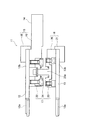
図8に、カフスサポータ装着工程で使用されるカフスサポート機構11を上側から見た斜視図により示す。図9に、同じくカフスサポート機構11を下側から見た斜視図により示す。図10に、弾性変形していない状態のカフスサポート機構11を説明図により示す。図11に、軸方向に弾性変形した状態のカフスサポート機構11を説明図により示す。図12に、ステータコア2にカフスサポート機構11を装着した状態を説明図により示す。
FIG. 8 is a perspective view of the
図12に示すカフスサポート機構11は、図8〜図11に示すように、上側カフスサポータ12と、下側カフスサポータ13と、カフスサポータ保持部材14とから構成される。図12に示すように、上側カフスサポータ12は、その先端部12aがステータコア2のティース4のうち上面2a上に配置され、その基端部12bがステータコア2の径方向外側に配置される。また、下側カフスサポータ13は、その先端部13aがステータコア2のティース4のうち下面2b上に配置され、基端部13bがステータコア2の径方向外側に配置される。そして、これら上側カフスサポータ12と下側カフスサポータ13は、ステータコア2の径方向外側においてカフスサポータ保持部材14によって固定される。
As shown in FIGS. 8 to 11, the
このカフスサポータ保持部材14は、上側保持部15と下側保持部16と弾性部17とからなる。従って、カフスサポータ保持部材14は、簡易な構造となっている。上側保持部15は、環状の上側保持第1部材18と、中央に開口を有する板状の上側保持第2部材19とからなり、これらの間に上側カフスサポータ12を挟んで上側カフスサポータ12を保持する。また、下側保持部16は、環状の下側保持第1部材20と、環状の下側保持第2部材21とからなり、これらの間に下側カフスサポータ13を挟んで下側カフスサポータ13を保持する。
The cuff
図9に示すように、弾性部17は、上側保持部15と下側保持部16との間に、周方向に均等な間隔で周方向に6カ所に配設されている。図10,11に示すように、この弾性部17は、概略円盤状をなし、上側保持部15の上側保持第2部材19にボルトで固定される上側カラー部材22と、突出部23aを有する概略円盤状をなし、下側保持部16の下側保持第2部材21にボルトで固定される下側カラー部材23と、下側カラー部材23の突出部23aが貫通した状態で上側カラー部材22と下側カラー部材23との間に配置された弦巻バネ24とからなる。
As shown in FIG. 9, the
カフスサポート機構11は、このような構成とされるため、軸方向に押圧力が掛かると、図11に示すように、弾性部17が軸方向に弾性変形(圧縮変形)し、上側カフスサポータ12と下側カフスサポータ13との平行な状態を保ちつつ、上側カフスサポータ12と下側カフスサポータ13との間隔を縮めることができる。すなわち、この実施形態のカフスサポート機構11は、軸方向の押圧力に応じて上側カフスサポータ12と下側カフスサポータ13との間隔が可変となっている。
Since the
図12に示すように、カフスサポート機構11を、コイル挿入工程に先立って、スロット5にスロット紙7が挿入されたステータコア2の上下両面2a,2bを挟むように装着
される。すなわち、上側カフスサポータ12は、その先端部12aをステータコア2のティース4上に配置すると共に、その基端部12bをステータコア2の径方向外側に配置する。また、下側カフスサポータ13は、その先端部13aをステータコア2のティース4上に配置すると共に、その基端部13aをステータコア2の径方向外側に配置する。また、上側カフスサポータ12及び下側カフスサポータ13をステータコア2の径方向外側においてカフスサポータ保持部材14により保持する。
As shown in FIG. 12, the
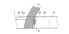
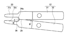
ここで、上側カフスサポータ12と下側カフスサポータ13の構成について詳しく説明する。この実施形態では、上側カフスサポータ12及び下側カフスサポータ13は同じ構成を有することから、ここでは上側カフスサポータ12について説明し、下側カフスサポータ13の説明は省略する。図13に、ステータコア2のティース4の間に形成される一つのスロット5に対応した一組の上側カフスサポータ12を平面図により示す。図14に、図13のA−A線に沿って切り離した一つの棒状体31の一部を側面図により示す。図13,14から分かるように、カフスサポート機構11は、上記一組の上側カフスサポータ12及び下側カフスサポータ13を複数組を備える。上側カフスサポータ12は、図6に示すように、ステータコア2のスロット5に挿入されるスロット紙7の上側のカフス部7aを、隣接する二本の棒状体31,32の先端部31a,32aより形成される二股部33により囲い保護するようになっている。二股部33の内側頂部には、二本の棒状体31,32の合わせ面34の端に継ぎ目34aができる。二股部33の内壁において、継ぎ目34aの近傍には、スロット紙7の後にスロット5に挿入されるコイル3からカフス部7aを退ける庇部35が設けられる。図14に示すように、この庇部35は、その下面に鋭角な角部を有する形状となっている。この庇部35の下にスロット紙7のカフス部7aが入り込むようになっている。
Here, the configuration of the
そして、上記のようにカフスサポータ装着工程において、カフスサポート機構11を用いて上側及び下側のカフスサポータ12,13をステータコア2に装着した後、コイル挿入工程を実施して各スロット5にコイル3を挿入する。コイル挿入工程では、スロット紙7が挿入され、上側及び下側のカフスサポータ12,13が装着された状態で、図15に示すように、各カフスサポータ12,13の庇部35によりスロット紙7のカフス部7a,7bをコイル3から退けながらスロット5にコイル3を挿入する。
Then, in the cuff supporter mounting process as described above, the upper and
その後、ステータコア2の上面2aから突出するコイル3の上側エンドと、ステータコア2の下面2bから突出するコイル3の下側エンドのそれぞれを所要形状に圧縮成形することにより、コイルエンド成形工程が実施される。このようにして、図1に示すステータ1が製造される。
Thereafter, the coil end molding process is performed by compression molding the upper end of the
以上説明したこの実施形態のカフスサポータ12,13によれば、隣接する二本の棒状体31,32の先端部31a,32aより形成される二股部33の内側頂部には、二本の棒状体31,32の合わせ面34の継ぎ目34aがあるが、その二股部33の内側の継ぎ目34aの近傍に庇部35が設けられる。従って、図15に示すように、スロット紙7の後にスロット5にコイル3が挿入されても、スロット紙7のカフス部7a(7b)がこの庇部35によりコイル3から退けられるので、カフス部7a(7b)がコイル3によって継ぎ目34aに押し付けられることがない。この結果、コイル3の押し付けによりスロット紙7のカフス部7a(7b)が破損することを防止することができる。
According to the
また、この実施形態のステータ製造方法によれば、スロット紙挿入工程によりスロット5にスロット紙7が挿入され、カフスサポータ装着工程によりスロット5に挿入されたスロット紙7に対応して、ステータコア2の上下両面2a,2bに対し上側及び下側のカフスサポータ12,13が装着される。この装着状態では、ステータコア2の上下両面2a,2bから、スロット紙7のカフス部7a,7bが突出し、そのカフス部7a,7bを、
カフスサポータ12,13の二股部33により囲まれた状態となる。その後、コイル挿入工程では、スロット紙7が挿入され、カフスサポータ12,13が装着された状態で、スロット5にコイル3が挿入される。このとき、スロット紙7のカフス部7a,7bがコイル3により押圧されるが、カフスサポータ12,13の庇部35によりカフス部7a,7bがコイル3から退けられるので、コイル3によりカフス部7a,7bが継ぎ目に押し付けられることがない。この結果、コイル3の押し付けによりスロット紙7のカフス部7a,7bが破損することを防止することができる。
Further, according to the stator manufacturing method of this embodiment, the
The
[第2実施形態]
次に、本発明のカフスサポータ及びそれを用いたステータ製造方法を具体化した第2実施形態につき図面を参照して詳細に説明する。なお、この実施形態で、第1実施形態と同じ構成については、同一の符号を付して説明を省略し、以下には異なった点を中心に説明する。
[Second Embodiment]
Next, a cuff supporter according to the present invention and a stator manufacturing method using the same will be described in detail with reference to the drawings. In this embodiment, the same components as those in the first embodiment are denoted by the same reference numerals, description thereof is omitted, and different points will be mainly described below.
この実施形態では、上側及び下側のカフスサポータ12,13の構成の点で第1実施形態と異なる。ここでも、上側カフスサポータ12のみについて説明する。図16に、一組の上側カフスサポータ12を平面図により示す。図17に、図16のB−B線に沿って切り離した一つの棒状体31の一部を側面図により示す。継ぎ目34aの部分を含む、二股部33の内壁には、スロット紙7の後にスロット5に挿入されるコイル3からカフス部7aを退ける庇部36が設けられる。この庇部36は、二股部33の内側全体にわたって設けられる。図17に示すように、この庇部36は、凸に湾曲した形状となっている。この庇部36の下にスロット紙7のカフス部7aが入り込むようになっている。
This embodiment differs from the first embodiment in the configuration of the upper and
従って、この実施形態でも、図18に示すように、スロット紙7の後にスロット5にコイル3が挿入されても、スロット紙7のカフス部7a(7b)がこの庇部36によりコイル3から退けられるので、第1実施形態と同様の作用効果を得ることができる。特に、この実施形態では、庇部36が二股部33の内側全体にわたって設けられるので、カフスサポータ12,13を構成する二本の棒状体31,32の継ぎ目34a以外の部分でも、スロット紙7のカフス部7a(7b)がコイル3によって二股部33に押し付けられることがない。このため、コイル3の押し付けによるカフス部7a(7b)の破損を広範囲に防止することができる。
Therefore, also in this embodiment, as shown in FIG. 18, even if the
なお、この発明は前記実施形態に限定されるものではなく、発明の趣旨を逸脱することのない範囲で以下のように実施することもできる。 In addition, this invention is not limited to the said embodiment, In the range which does not deviate from the meaning of invention, it can also implement as follows.
(1)前記第1実施形態では、二股部33の内壁の継ぎ目34aの近傍にのみ、下面に鋭角な角部を有する形状の庇部35を設けたが、この形状の庇部を二股部の内側全体にわたって設けてもよい。
(1) In the first embodiment, the
(2)前記第2実施形態では、二股部33の内側全体にわたって、凸に湾曲した形状の庇部36を設けたが、この形状の庇部を二股部の内壁の継ぎ目の近傍にのみ設けてもよい。
(2) In the second embodiment, the
1 ステータ
2 ステータコア
2a 上面
2b 下面
3 コイル
5 スロット
7 スロット紙
7a カフス部
7b カフス部
12 上側カフスサポータ
12a 先端部
13 下側カフスサポータ
13a 先端部
31 棒状体
32 棒状体
33 二股部
34 合わせ面
34a 継ぎ目
35 庇部
36 庇部
DESCRIPTION OF
Claims (3)
前記二股部の内側頂部には、前記二本の棒状体の合わせ面の継ぎ目があり、前記二股部の内側の少なくとも前記継ぎ目の近傍に、前記スロット紙の後に前記スロットに挿入されるコイルから前記カフス部を退ける庇部を設け、
前記庇部は、前記二股部の内壁がその縁部にて張り出した部分であることを特徴とするカフスサポータ。 A cuff supporter that protects a cuff portion of slot paper inserted into a slot of a stator core with a bifurcated portion formed by tip portions of two adjacent rod-shaped bodies,
At the inner top of the bifurcated portion, there is a seam of the mating surfaces of the two rod-shaped bodies, and at least in the vicinity of the seam inside the bifurcated portion, from the coil inserted into the slot after the slot paper set the eaves portion to reject the cuff,
The cuff supporter is characterized in that the collar portion is a portion where an inner wall of the bifurcated portion projects at an edge thereof .
前記ステータコアの上下両面に対し、前記スロットに挿入された前記スロット紙に対応して、請求項1に記載されたカフスサポータを装着するカフスサポータ装着工程と、
前記スロット紙が挿入され、前記カフスサポータが装着された状態で、前記カフスサポータの前記庇部により前記スロット紙の前記カフス部を前記コイルから退けながら前記スロットにコイルを挿入するコイル挿入工程と
を備えたことを特徴とするカフスサポータを用いたステータ製造方法。 A slot paper insertion step of inserting slot paper having cuff portions up and down into slots of the stator core so that the cuff portions protrude from both upper and lower surfaces of the stator core; and
A cuff supporter mounting step for mounting the cuff supporter according to claim 1, corresponding to the slot paper inserted into the slot, on both upper and lower surfaces of the stator core;
A coil insertion step of inserting the coil into the slot while the slot paper is inserted and the cuff supporter is mounted, while the cuff portion of the cuff supporter moves the cuff portion of the slot paper away from the coil. A stator manufacturing method using a cuff supporter, comprising:
Priority Applications (1)
| Application Number | Priority Date | Filing Date | Title |
|---|---|---|---|
| JP2008002483A JP5233284B2 (en) | 2008-01-09 | 2008-01-09 | Cuff supporter and stator manufacturing method using the same |
Applications Claiming Priority (1)
| Application Number | Priority Date | Filing Date | Title |
|---|---|---|---|
| JP2008002483A JP5233284B2 (en) | 2008-01-09 | 2008-01-09 | Cuff supporter and stator manufacturing method using the same |
Publications (3)
| Publication Number | Publication Date |
|---|---|
| JP2009165312A JP2009165312A (en) | 2009-07-23 |
| JP2009165312A5 JP2009165312A5 (en) | 2010-08-05 |
| JP5233284B2 true JP5233284B2 (en) | 2013-07-10 |
Family
ID=40967262
Family Applications (1)
| Application Number | Title | Priority Date | Filing Date |
|---|---|---|---|
| JP2008002483A Expired - Fee Related JP5233284B2 (en) | 2008-01-09 | 2008-01-09 | Cuff supporter and stator manufacturing method using the same |
Country Status (1)
| Country | Link |
|---|---|
| JP (1) | JP5233284B2 (en) |
Cited By (1)
| Publication number | Priority date | Publication date | Assignee | Title |
|---|---|---|---|---|
| EP4024684A1 (en) * | 2020-04-10 | 2022-07-06 | Jee Technology Co., Ltd. | Positioning and guiding device for inserting flat wire hairpins into stator |
Families Citing this family (5)
| Publication number | Priority date | Publication date | Assignee | Title |
|---|---|---|---|---|
| JP5321129B2 (en) * | 2009-02-25 | 2013-10-23 | トヨタ自動車株式会社 | Stator manufacturing method and stator manufacturing apparatus |
| JP6358086B2 (en) * | 2014-12-26 | 2018-07-18 | アイシン・エィ・ダブリュ株式会社 | Stator assembly apparatus and stator assembly method |
| DE112016003633T5 (en) * | 2015-09-30 | 2018-04-26 | Aisin Aw Co., Ltd. | Statormontageverfahren |
| WO2019189934A1 (en) * | 2018-03-30 | 2019-10-03 | 株式会社小田原エンジニアリング | Method for preventing location aberration of insulation sheet and device for preventing location aberration of insulation sheet |
| JPWO2019208099A1 (en) * | 2018-04-27 | 2021-02-12 | アイシン・エィ・ダブリュ株式会社 | Stator and how to manufacture the stator |
Family Cites Families (2)
| Publication number | Priority date | Publication date | Assignee | Title |
|---|---|---|---|---|
| JPH0833290A (en) * | 1994-07-14 | 1996-02-02 | Toshiba Corp | Method and apparatus for inserting insulator into slot |
| JPH1127889A (en) * | 1997-06-30 | 1999-01-29 | Hitachi Ltd | Stator of dynamoelectric machine and its manufacturing method |
-
2008
- 2008-01-09 JP JP2008002483A patent/JP5233284B2/en not_active Expired - Fee Related
Cited By (2)
| Publication number | Priority date | Publication date | Assignee | Title |
|---|---|---|---|---|
| EP4024684A1 (en) * | 2020-04-10 | 2022-07-06 | Jee Technology Co., Ltd. | Positioning and guiding device for inserting flat wire hairpins into stator |
| EP4024684A4 (en) * | 2020-04-10 | 2023-09-27 | Jee Technology Co., Ltd. | Positioning and guiding device for inserting flat wire hairpins into stator |
Also Published As
| Publication number | Publication date |
|---|---|
| JP2009165312A (en) | 2009-07-23 |
Similar Documents
| Publication | Publication Date | Title |
|---|---|---|
| JP5233284B2 (en) | Cuff supporter and stator manufacturing method using the same | |
| JP2009165312A5 (en) | ||
| KR102387991B1 (en) | Stator and motor using the same | |
| US11502586B2 (en) | Stator of a motor | |
| WO2011102536A1 (en) | Crimping apparatus for shielded wire and method for end-processing shielded wire | |
| JP4344529B2 (en) | Stator core | |
| WO2016132470A1 (en) | Rotating electric machine stator | |
| JP4764048B2 (en) | Interphase insulation paper for rotating electrical machines | |
| JP5282153B1 (en) | Resolver stator and method of manufacturing stator assembly | |
| JP2016093055A (en) | Stator core assembly | |
| JP5991308B2 (en) | Stator manufacturing method | |
| JP2008253037A (en) | Inter-phase insulator | |
| JP2007259649A (en) | Insulation member and method of assembling same | |
| WO2014024987A1 (en) | Stator, stator core for stator, stator core production method, and sheet core bending device | |
| JP2019004662A (en) | Cuff supporter, inter-phase insulating paper, and manufacturing method of motor | |
| JP5330079B2 (en) | Insulator, armature, and manufacturing method of armature | |
| WO2015111214A1 (en) | Cold-welded conductor wire, electric motor, and electric motor manufacturing method | |
| JP5521642B2 (en) | Armature of rotating electric machine and method for manufacturing the armature | |
| JP2009176677A (en) | Insulating protection method of terminal | |
| JP4215001B2 (en) | Interphase insulating paper and stator using the interphase insulating paper | |
| JP2010259174A (en) | Method of manufacturing motor stators | |
| JP2013121298A (en) | Method for fitting interphase insulation paper, interphase insulation paper and method for manufacturing interphase insulation paper | |
| WO2013190724A1 (en) | Wire harness sheath and wire-harness protection structure | |
| JP5479840B2 (en) | Protective cover for ground wire attachment point and its attachment method | |
| JP6432431B2 (en) | Coil component and method for forming coil component |
Legal Events
| Date | Code | Title | Description |
|---|---|---|---|
| A521 | Request for written amendment filed |
Free format text: JAPANESE INTERMEDIATE CODE: A523 Effective date: 20100617 |
|
| A621 | Written request for application examination |
Free format text: JAPANESE INTERMEDIATE CODE: A621 Effective date: 20100617 |
|
| A131 | Notification of reasons for refusal |
Free format text: JAPANESE INTERMEDIATE CODE: A131 Effective date: 20120904 |
|
| A977 | Report on retrieval |
Free format text: JAPANESE INTERMEDIATE CODE: A971007 Effective date: 20120905 |
|
| A521 | Request for written amendment filed |
Free format text: JAPANESE INTERMEDIATE CODE: A523 Effective date: 20121008 |
|
| TRDD | Decision of grant or rejection written | ||
| A01 | Written decision to grant a patent or to grant a registration (utility model) |
Free format text: JAPANESE INTERMEDIATE CODE: A01 Effective date: 20130226 |
|
| A61 | First payment of annual fees (during grant procedure) |
Free format text: JAPANESE INTERMEDIATE CODE: A61 Effective date: 20130311 |
|
| R151 | Written notification of patent or utility model registration |
Ref document number: 5233284 Country of ref document: JP Free format text: JAPANESE INTERMEDIATE CODE: R151 |
|
| FPAY | Renewal fee payment (event date is renewal date of database) |
Free format text: PAYMENT UNTIL: 20160405 Year of fee payment: 3 |
|
| LAPS | Cancellation because of no payment of annual fees |