JP5231201B2 - Terminal block and method for assembling the terminal block - Google Patents
Terminal block and method for assembling the terminal block Download PDFInfo
- Publication number
- JP5231201B2 JP5231201B2 JP2008331276A JP2008331276A JP5231201B2 JP 5231201 B2 JP5231201 B2 JP 5231201B2 JP 2008331276 A JP2008331276 A JP 2008331276A JP 2008331276 A JP2008331276 A JP 2008331276A JP 5231201 B2 JP5231201 B2 JP 5231201B2
- Authority
- JP
- Japan
- Prior art keywords
- coil spring
- housing
- spring
- terminal block
- slit
- Prior art date
- Legal status (The legal status is an assumption and is not a legal conclusion. Google has not performed a legal analysis and makes no representation as to the accuracy of the status listed.)
- Expired - Fee Related
Links
- 238000000034 method Methods 0.000 title description 5
- 230000002093 peripheral effect Effects 0.000 claims description 4
- 238000003780 insertion Methods 0.000 description 17
- 230000037431 insertion Effects 0.000 description 17
- 239000000523 sample Substances 0.000 description 8
- 239000004020 conductor Substances 0.000 description 6
- 230000035515 penetration Effects 0.000 description 5
- WABPQHHGFIMREM-UHFFFAOYSA-N lead(0) Chemical compound [Pb] WABPQHHGFIMREM-UHFFFAOYSA-N 0.000 description 4
- 230000000149 penetrating effect Effects 0.000 description 4
- 239000000758 substrate Substances 0.000 description 4
- 238000005452 bending Methods 0.000 description 3
- 239000002184 metal Substances 0.000 description 3
- 229910052751 metal Inorganic materials 0.000 description 3
- 238000003825 pressing Methods 0.000 description 2
- 238000005476 soldering Methods 0.000 description 2
- RYGMFSIKBFXOCR-UHFFFAOYSA-N Copper Chemical compound [Cu] RYGMFSIKBFXOCR-UHFFFAOYSA-N 0.000 description 1
- 125000002066 L-histidyl group Chemical group [H]N1C([H])=NC(C([H])([H])[C@](C(=O)[*])([H])N([H])[H])=C1[H] 0.000 description 1
- 229910052802 copper Inorganic materials 0.000 description 1
- 239000010949 copper Substances 0.000 description 1
- 238000005520 cutting process Methods 0.000 description 1
- 238000010586 diagram Methods 0.000 description 1
- 230000014509 gene expression Effects 0.000 description 1
- 239000000463 material Substances 0.000 description 1
- 238000012986 modification Methods 0.000 description 1
- 230000004048 modification Effects 0.000 description 1
- 238000004080 punching Methods 0.000 description 1
- 239000011347 resin Substances 0.000 description 1
- 229920005989 resin Polymers 0.000 description 1
- 238000000926 separation method Methods 0.000 description 1
- 238000003860 storage Methods 0.000 description 1
Images


Classifications
-
- H—ELECTRICITY
- H01—ELECTRIC ELEMENTS
- H01R—ELECTRICALLY-CONDUCTIVE CONNECTIONS; STRUCTURAL ASSOCIATIONS OF A PLURALITY OF MUTUALLY-INSULATED ELECTRICAL CONNECTING ELEMENTS; COUPLING DEVICES; CURRENT COLLECTORS
- H01R4/00—Electrically-conductive connections between two or more conductive members in direct contact, i.e. touching one another; Means for effecting or maintaining such contact; Electrically-conductive connections having two or more spaced connecting locations for conductors and using contact members penetrating insulation
- H01R4/28—Clamped connections, spring connections
- H01R4/48—Clamped connections, spring connections utilising a spring, clip, or other resilient member
- H01R4/489—Clamped connections, spring connections utilising a spring, clip, or other resilient member spring force increased by screw, cam, wedge, or other fastening means
-
- H—ELECTRICITY
- H01—ELECTRIC ELEMENTS
- H01R—ELECTRICALLY-CONDUCTIVE CONNECTIONS; STRUCTURAL ASSOCIATIONS OF A PLURALITY OF MUTUALLY-INSULATED ELECTRICAL CONNECTING ELEMENTS; COUPLING DEVICES; CURRENT COLLECTORS
- H01R4/00—Electrically-conductive connections between two or more conductive members in direct contact, i.e. touching one another; Means for effecting or maintaining such contact; Electrically-conductive connections having two or more spaced connecting locations for conductors and using contact members penetrating insulation
- H01R4/28—Clamped connections, spring connections
- H01R4/48—Clamped connections, spring connections utilising a spring, clip, or other resilient member
- H01R4/4809—Clamped connections, spring connections utilising a spring, clip, or other resilient member using a leaf spring to bias the conductor toward the busbar
- H01R4/4828—Spring-activating arrangements mounted on or integrally formed with the spring housing
- H01R4/48365—Spring-activating arrangements mounted on or integrally formed with the spring housing with integral release means
-
- H—ELECTRICITY
- H01—ELECTRIC ELEMENTS
- H01R—ELECTRICALLY-CONDUCTIVE CONNECTIONS; STRUCTURAL ASSOCIATIONS OF A PLURALITY OF MUTUALLY-INSULATED ELECTRICAL CONNECTING ELEMENTS; COUPLING DEVICES; CURRENT COLLECTORS
- H01R4/00—Electrically-conductive connections between two or more conductive members in direct contact, i.e. touching one another; Means for effecting or maintaining such contact; Electrically-conductive connections having two or more spaced connecting locations for conductors and using contact members penetrating insulation
- H01R4/28—Clamped connections, spring connections
- H01R4/48—Clamped connections, spring connections utilising a spring, clip, or other resilient member
- H01R4/4854—Clamped connections, spring connections utilising a spring, clip, or other resilient member using a wire spring
- H01R4/4863—Coil spring
- H01R4/4872—Coil spring axially compressed to retain wire end
-
- H—ELECTRICITY
- H01—ELECTRIC ELEMENTS
- H01R—ELECTRICALLY-CONDUCTIVE CONNECTIONS; STRUCTURAL ASSOCIATIONS OF A PLURALITY OF MUTUALLY-INSULATED ELECTRICAL CONNECTING ELEMENTS; COUPLING DEVICES; CURRENT COLLECTORS
- H01R43/00—Apparatus or processes specially adapted for manufacturing, assembling, maintaining, or repairing of line connectors or current collectors or for joining electric conductors
- H01R43/20—Apparatus or processes specially adapted for manufacturing, assembling, maintaining, or repairing of line connectors or current collectors or for joining electric conductors for assembling or disassembling contact members with insulating base, case or sleeve
- H01R43/22—Hand tools
-
- Y—GENERAL TAGGING OF NEW TECHNOLOGICAL DEVELOPMENTS; GENERAL TAGGING OF CROSS-SECTIONAL TECHNOLOGIES SPANNING OVER SEVERAL SECTIONS OF THE IPC; TECHNICAL SUBJECTS COVERED BY FORMER USPC CROSS-REFERENCE ART COLLECTIONS [XRACs] AND DIGESTS
- Y10—TECHNICAL SUBJECTS COVERED BY FORMER USPC
- Y10T—TECHNICAL SUBJECTS COVERED BY FORMER US CLASSIFICATION
- Y10T29/00—Metal working
- Y10T29/49—Method of mechanical manufacture
- Y10T29/49002—Electrical device making
- Y10T29/49117—Conductor or circuit manufacturing
- Y10T29/49204—Contact or terminal manufacturing
Description
本発明は、レバーを備えたプッシュ式端子台等の端子台及び該端子台の組立方法に関する。 The present invention relates to a terminal block such as a push-type terminal block having a lever and a method for assembling the terminal block.
プッシュ式のレバーを押し下げることにより端子挿入孔内にケーブル導体又はケーブル先端に取り付けられたリード端子を挿入可能にして、ケーブル導体又はリード端子と内部の接続端子との導通接続を図るいわゆるプッシュ式端子台は、例えばオーディオ機器の背面に、多くの場合複数連設されて使用されている。例えば特許文献1には、「リード線Aを第1固定部20に固定し接続する場合には、図3(b)に示すように、レバー3を圧接部15の後端縁15aを支点として座具2上で傾動させて摺動軸4を引き上げる。これによって、第1挿入孔5と第2挿入孔13とを一致させて両挿入孔5、13にリード線Aを挿入する」と記載されている。
A so-called push-type terminal that allows a cable conductor or a lead terminal attached to the end of the cable to be inserted into the terminal insertion hole by pushing down a push-type lever, thereby conducting a conductive connection between the cable conductor or the lead terminal and the internal connection terminal. For example, in many cases, a plurality of platforms are used in series on the back of an audio device. For example, in Patent Document 1, “When the lead wire A is fixed and connected to the first fixing portion 20, the lever 3 is used with the rear end edge 15 a of the press contact portion 15 as a fulcrum as shown in FIG. The sliding shaft 4 is lifted by tilting on the
レバーのような可動部を備えた端子台では、該レバーを所定の方向に付勢するためのコイルばねを使用する場合が多い。例えば特許文献2には、「第3図(イ)に示す様にばね止め板11に切起し片22を設け、該切起し片22にコイルばね8の後端部をひっかけ、同図(ロ)に示すように、該ばね止め板11をケース1のばね挿入孔9を塞ぐ方向に折り曲げる一動作で切起し片22でコイルばね8を前方に押圧する」と記載されている。
In a terminal block having a movable part such as a lever, a coil spring for biasing the lever in a predetermined direction is often used. For example, in
また特許文献3には、「第3図において、C方向より復帰ばね15を組込むと、収納部14に設けた凸状の柱21によって、復帰ばね15はD部のスキマに噛み込まずスムースに組立てることができる」と記載されている。 Further, in Patent Document 3, “in FIG. 3, when the return spring 15 is assembled from the direction C, the return spring 15 is smoothly bitten by the convex column 21 provided in the storage portion 14 without being caught in the gap of the D portion. It can be assembled ".
近年のプッシュ式端子台等の端子台は、使用される装置の小型化や機器の複雑化に伴い、よりコンパクトなものが求められ、故に端子台を構成する各要素にも必然的に小型化が求められる。具体的には、端子台が有する各端子用挿入孔を開口するためのプッシュレバー及び該プッシュレバーをプッシュ方向の反対方向に付勢するコイルばねにも小型化が要求される。一方、該レバーやコイルばねの組み立ては通常手作業で行われ、これらの要素の小型化は該手作業を困難なものとする。特に、コイルばねは圧縮した状態でレバーに係合させてハウジング内に配置する必要がある場合が多く、圧縮されたコイルばねはその復元力によって作業者の手元から不意に離れる等の不都合を招く虞がある。 In recent years, terminal blocks such as push-type terminal blocks are required to be more compact as the equipment used and the equipment become more complex. Therefore, the elements constituting the terminal block are inevitably downsized. Is required. Specifically, the push lever for opening each terminal insertion hole of the terminal block and the coil spring that biases the push lever in the direction opposite to the push direction are also required to be downsized. On the other hand, the lever and the coil spring are usually assembled manually, and the miniaturization of these elements makes the manual operation difficult. In particular, the coil spring often needs to be engaged with a lever in a compressed state and disposed in the housing, and the compressed coil spring causes inconveniences such as unintentional separation from the operator's hand due to its restoring force. There is a fear.
そこで本発明は、コイルばねの装着作業を容易に行える構造を備えた端子台、及び該端子台の組立方法を提供する。 Therefore, the present invention provides a terminal block having a structure capable of easily mounting a coil spring, and a method for assembling the terminal block.
上記目的を達成するために、本発明の一態様によれば、ハウジングと、前記ハウジングに可動に配置された少なくとも1つのレバー部材と、前記ハウジング内に配置されるとともに、前記少なくとも1つのレバー部材を所定の方向に付勢する少なくとも1つのコイルばねと、前記コイルばねの一端を支持可能に構成されたばね受け部と、前記コイルばねを前記ハウジング内に挿入するための、該ハウジングに形成された開口部と、前記ハウジングの前記開口部に連通するとともに、前記ばね受け部内を少なくとも部分的に延びかつ前記コイルばねの外径より短い幅を備えたスリットと、を有する端子台が提供される。 To achieve the above object, according to one aspect of the present invention, a housing, at least one lever member movably disposed in the housing, and at least one lever member disposed in the housing. At least one coil spring for urging the coil spring in a predetermined direction, a spring receiving portion configured to be able to support one end of the coil spring, and the housing for inserting the coil spring into the housing. There is provided a terminal block having an opening and a slit communicating with the opening of the housing and extending at least partially within the spring receiving portion and having a width shorter than the outer diameter of the coil spring.
本発明の他の態様によれば、少なくとも1つのレバー部材が可動に配置されたハウジングを用意するステップと、前記少なくとも1つのレバー部材を所定の方向に付勢するコイルばねを保持可能である保持部を備えた治具を用意するステップと、前記コイルばねの一端を前記保持部に係合させて、前記コイルばねを前記ハウジングに形成された開口部から挿入するステップと、前記コイルばねの他端を、前記ハウジング内で前記レバー部材の部分に係合させるステップと、前記治具を前記ハウジング内に押し込んで前記コイルばねを圧縮させるステップと、前記ハウジングの前記開口部に連通するとともに、前記コイルばねの一端を支持可能に形成された前記ハウジング内のばね受け部内を少なくとも部分的に延びかつ前記コイルばねの外径より短い幅を備えたスリット内を前記治具の前記保持部が通るように、前記コイルばねが圧縮された状態で前記治具を移動させるステップと、前記保持部が前記スリット内を通っている状態で前記治具を引き抜いて、前記コイルばねの一端を前記ばね受け部に当接させるステップと、を有する端子台の組立方法が提供される。 According to another aspect of the present invention, a step of preparing a housing in which at least one lever member is movably disposed, and a holding capable of holding a coil spring that biases the at least one lever member in a predetermined direction. Providing a jig having a portion, engaging one end of the coil spring with the holding portion, and inserting the coil spring from an opening formed in the housing; Engaging the end with the portion of the lever member within the housing, pressing the jig into the housing to compress the coil spring, communicating with the opening of the housing, and An outer diameter of the coil spring extending at least partially within a spring receiving portion in the housing formed to be capable of supporting one end of the coil spring A step of moving the jig while the coil spring is compressed so that the holding portion of the jig passes through a slit having a shorter width, and the holding portion passes through the slit. And pulling out the jig in a state to bring one end of the coil spring into contact with the spring receiving portion.
本発明によれば、端子台が小型化された場合であっても、レバーを付勢するコイルばねの着脱を容易かつ確実に行うことができる。 According to the present invention, even when the terminal block is downsized, the coil spring that biases the lever can be easily and reliably attached and detached.
図1は、本発明に係る端子台の一実施形態としてプッシュ式端子台(以降、単に端子台と称する)1を示す外観斜視図であり、図2は図1の端子台1の底面図であり、図3は図2のIII−III断面図である。図示される端子台1は、ハウジング2と、ハウジング2に可動に設けられた第1及び第2レバー部材3a及び3bと、導電性材料からなる第1及び第2接続端子4a及び4b(第2接続端子4bは図2に図示)と、第1及び第2レバー部材3a及び3bをそれぞれ付勢する第1及び第2付勢部材であるコイルばね5a及び5b(第1付勢部材5aのみ図3に図示)とを有する。ハウジング2は任意の材料から作製することが可能であり、例えば金属や樹脂から作製可能である。図1に示すように、ハウジング2は各接続端子と導通接続すべきケーブル導体又はケーブル先端に取り付けられたリード端子(以降、まとめてリード線と称する)を挿通可能な挿入孔21a、21bを上面22に有する。
FIG. 1 is an external perspective view showing a push-type terminal block (hereinafter simply referred to as a terminal block) 1 as an embodiment of the terminal block according to the present invention, and FIG. 2 is a bottom view of the terminal block 1 of FIG. 3 is a cross-sectional view taken along the line III-III in FIG. The illustrated terminal block 1 includes a
図3に示すように、第1接続端子4aは、銅等の金属板から曲げ加工や打ち抜き加工により作製可能であり、全体として略L字形状を呈しており、背面部41a及び屈曲した脚部42aを有し、脚部42aがハウジング2の底部24に形成された溝部241a(図2参照)に係合することにより、ハウジング2内に固定できるようになっている。また接続端子4aは、挿入孔21aに挿入されたリード線6a(図3に破線で図示)に接触するための2つの突起43a、44aを有する。突起43a、44aは、金属板の一部の曲げや切り起こし等の加工により形成可能であり、挿入されたリード線の長手方向に互いに所定距離離れている。さらに接続端子4aの脚部42aは、ハウジング2の底部24(すなわち図3に概略図示した基板7に接続されるハウジング面)から突出するように構成されており、脚部42aは基板7に設けられた貫通孔(図示せず)に半田付け等により導通接続される。或いは、接続端子の脚部42aを基板面と略平行に折り曲げて表面実装に適した形状とし、基板表面の導体部(ランド)と半田付け等によって導通接続することもできる。他方の接続端子4bについても、同様の構成とすることができる。
As shown in FIG. 3, the
図3に示すように、第1レバー部材3aは、その末端部に設けられた支軸31aを中心に旋回可能に構成される。支軸31aは、略L字形状の接続端子4aの屈曲部46aの近傍かつ内側に配置される。また第1レバー部材3aは、支軸31aから接続端子4aとは反対側に延びる本体部32aと、本体部32a上であって支軸31aからレバー部の長手方向にいくらか離れた位置に形成された突部33aとを有する。例えばコイルばねからなる第1付勢部材5aは、その一端51aが突部33aに係合し、他端52aがハウジング2の底部24に形成されたばね受け部25a内に保持されており、レバー部材3aを、第1接続端子4aの2つの突起43a及び44aの近傍に設けられた第1レバー部材3aの楔部34aが2つの突起43aと44aとの間に位置するように(図示例では上方)に付勢する。なお本願における「ハウジング内に配置」等の表現は、例えばコイルばねが完全にハウジング内部に収容される形態のみを意味するものではなく、その一部がハウジング内に配置される場合も含む。例えばコイルばねの一部がハウジングの一面から外部に突出していたり、ハウジングの壁面部分が少ない(開口部が多い)ためにコイルばねが実質的に覆われていない場合も含まれる。
As shown in FIG. 3, the
第2レバー部材3b及び第2レバー部材3bを付勢する第2コイルばね(図示せず)についても、第1レバー部材3aと同様の構成とすることができる。但し図示例では、作業者が第1レバー部材3aのみを操作しようとした場合に誤って隣接する第2レバー部材3bも操作してしまうことを防止するために、図3に示すように、第1レバー部材3aの操作部35aと第2レバー部材3bの操作部35bとを、作業者が手を離した状態でのそれぞれの位置が異なるように、各レバー部材が構成されている。
The
図4は、端子台1の上面図である。挿入孔21a及び21bはそれぞれ、ケーブル用貫通部211a及び211bと、ケーブル用貫通部と連通したプローブ用貫通部212a及び212bとを有している。ケーブル用貫通部211a及び211bは略円形の貫通孔であり、その上面22側の端部にそれぞれ傾斜面213a及び213bを有する。ケーブル用貫通部の直径は、挿入されるケーブルの外径よりも多少大きい寸法に設定されている。一方プローブ用貫通部は略矩形の貫通孔であり、その幅Wはケーブル用貫通部の直径よりも小さく設定されている。幅Wは、挿入孔に挿入されるケーブルの導体の太さよりも小さくすることができる。挿入孔21a及び21b直下のハウジング内側には、上述の接続端子4a及び4bの突起43a及び43bが配置されている。ハウジング2の上面から見たときに、突起の先端は円形の貫通孔のおよそ円周上に位置する。
FIG. 4 is a top view of the terminal block 1. The
ケーブルが挿入孔に挿入された状態において、プローブ用貫通部212a及び212bの各々にはテスター等の探針を挿入して接続端子の突起43a、43bと導通させることができ、これにより端子台1に接続されたケーブルへの導電状態を検査することができる。プローブ用貫通部の幅Wはケーブル用貫通部の直径よりも小さいため、ケーブルをケーブル用貫通部に挿入するときに、ケーブル先端が誤ってプローブ用貫通部に挿入される可能性を低くし、挿入作業性を高めることができる。幅Wをケーブルの導体の太さよりも小さくすると、誤挿入をより効果的に防ぐことができる。また、外観的にもケーブル用貫通部がプローブ用貫通部よりも大きいため、作業者も容易にケーブル用貫通部とプローブ用貫通部とを識別することができる。
In a state where the cable is inserted into the insertion hole, a probe such as a tester can be inserted into each of the probe through
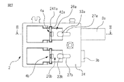
図2に示すように、ハウジング2の底部24には、端子4a及びコイルばね5aを挿入してハウジング2内に配置するための開口部26aと、端子4b及びコイルばね(図示せず)を挿入してハウジング2内に配置するための開口部26bとが形成される。また底部24には、開口部26aに連通するとともに上述のばね受け部25a内を略直線状に延びるスリット又は凹部27aが形成され、同様に、開口部26bに連通するとともに上述のばね受け部25b内を少なくとも部分的に略直線状に延びるスリット又は凹部27bが形成される。なお図示例でのスリット27aはばね受け部25aの中心を越えて略直線状に延びているが、スリット27aの長さはその先端がばね受け部25aに達する長さであればよい。またスリット27aは直線状に延びるものでなくともよく、例えばL字状やS字状に延びるものでもよい。
As shown in FIG. 2, an
図5は、ハウジング2の部品図を2つの断面図とともに示す。ばね受け部25aは、コイルばね5aの端部52a(図3参照)が当接する受け面251aと、受け面251aに当接したコイルばねの端部52aを、コイルばねの径方向にずれることを防止すべく保持するばね端部保持部252aとを有する。ばね端部保持部252aは、例えば受け面251aに略垂直に突出する部材であり、上述の受け面251aの外周部の一部であってスリット27aを塞がない位置(図示例では2箇所)に設けられる。スリット27aの幅はコイルばね5aの外径より短く、またスリット27aの長さは少なくともコイルばね5aの半径以上であることが好ましい。なおばね受け部25b及びスリット27bについても、それぞればね受け部25a及びスリット27aと同様の構成とできるので、詳細な説明は省略する。またばね受け部25aは、スリット27aと略反対側で受け面251aに隣接する壁部253aを有してもよく、この場合壁部253aもコイルばねの端部保持機能を備えることができる。また図5に示すような端部保持部252aの代わりに、受け面251aの略中央から突出するとともにコイルばね5aの内側寸法より小さい寸法を有する(すなわちコイルばね5aの端部内に挿入可能な)突起(図示せず)を設けてもよい。
FIG. 5 shows a component diagram of the
次に図6〜図12を参照して、本発明に係る端子台へのコイルばねの装着手順について説明する。なお以下の説明は端子台1のレバー3aの付勢に使用されるコイルばね5aについてのものであるが、他方のレバー3bについても同様である。
Next, with reference to FIGS. 6 to 12, a procedure for mounting the coil spring to the terminal block according to the present invention will be described. The following description is for the
先ず図6に示すように、コイルばね5aを端子台1のハウジング2内に装着するための治具8を用意する。治具8は、作業者が把持する好ましくは棒状の柄部81と、柄部81の端部に取り付けられてコイルばね5を保持する保持部82とを有する。保持部82は、全体として略U字状又はJ字状に形成された板状の部材であり、詳細には、コイルばね5aの内径より短い幅を有しかつコイルばね5aの長さより短い長さを備えた棒状又は細長い板状の挿入部すなわち第1突出部分821と、第1突出部分821から少なくともコイルばね5の線径に等しい長さだけ離隔配置された第2突出部分822と、第1及び第2の突出部分の間に形成され、コイルばね5aに挿入部821を挿入したときにコイルばね5aの一端52aに当接する底部823とを有する。また第2突出部822の突出長さは、後述する手順の操作性の観点から、第1突出部821より短いことが好ましい。また保持部82は全体としてスリット27aの幅以下の厚さを備えた部材から形成される。なお第2突出部分822は必須の構成要素ではなく、保持部82全体として棒状に構成してもよい。
First, as shown in FIG. 6, a
次に図7に示すように、コイルばね5aを治具8の保持部82に保持させた状態(具体的には治具8の挿入部821をコイルばね5a内に挿入した状態)で、治具8の保持部82を端子台1のハウジング2の底部開口部26aに接近させる。
Next, as shown in FIG. 7, the
さらに図8に示すように、コイルばね5を保持部82とともに底部開口部26a内に挿入していき、コイルばね5aの端部51aをプッシュレバー3aの突部33aに係合させる。突部33aの形状は図示のような半球形状に限られないが、突部33aに係合している間はコイルばね5aの端部51aの位置が実質変化しないようにすることが好ましい。また突部33aを形成する代わりにレバー部材3aに凹部を形成し、該凹部内にコイルばねの端部を係合させることもできる。
Further, as shown in FIG. 8, the coil spring 5 is inserted into the
次に図9に示すように、治具8を図8の状態からさらに、コイルばね5aが圧縮される方向に押し込む。ここで治具8の押込み長さは少なくとも、圧縮されたコイルばね5aの長さL1が、ばね受け部25aと突部33aとの間の距離L2よりも短くなるような長さである。
Next, as shown in FIG. 9, the
次に図10に示すように、コイルばね5aが圧縮された状態を維持しつつ、治具8を突部33aを支点としてばね受け部25a側に旋回させる。このとき、治具8の保持部82がハウジング2の底部に形成されたスリット27a内に挿入される。
Next, as shown in FIG. 10, the
次に図11に示すように、図10の状態から治具8を引き抜いて、圧縮されたコイルばね5aを復元させる。このとき、復元したコイルばね5aの一端52aがハウジング2のばね受け部25aの受け面251a(図5参照)に当接するように、治具8の保持部82がハウジング2のスリット27a内を通るように治具8を引き抜く。上述のように、スリット27aの幅は保持部82の幅より大きくかつコイルばねの外径よりは小さいので、保持部82をスリット27a内に通した状態で治具8を引き抜けば、治具8のみをスムースに引き抜くことができる。また図5に示したようにばね受け部25aはコイルばね5aの外周部に隣接するばね端部保持部252aを有しているので、ばね受け部25aに支持されたコイルばね5aの位置が装着後にずれることが防止される。
Next, as shown in FIG. 11, the
以上の操作により、図12に示すように、コイルばね5aを所定の状態、すなわちレバー部材3aの突部33aに一端51aが係合し、ハウジング2のばね受け部25aに他端52aが係合した状態で装着することができる。なおコイルばね5aをハウジング2内から取り外すときは、図7〜図11を用いて説明した操作を逆に行えばよい。
With the above operation, as shown in FIG. 12, the
図13は、ハウジングに形成されたばね受け部の代替例を示す図である。図13は、ハウジング2′の部品図を2つの断面図とともに示す。ばね受け部25a′は、コイルばね5aの端部52a(図3参照)が当接する受け面251a′と、受け面251a′に当接したコイルばねの端部52aを、コイルばねの径方向にずれることを防止すべく保持するばね端部保持部252a′とを有する。ばね受け部25a′は、ハウジング2の底部近傍にコイルばねの外径より僅かに大きい直径の円筒形状の凹部を形成してなり、受け面251a′はその凹部の底面に相当し、ばね端部保持部252a′は該円筒形状の側面に相当する。またハウジング2′の開口部26a′に連通するスリット27a′は、該円筒形状の凹部内をその直径方向に延びるように形成される。従ってこの場合も、ばね端部保持部252a′は受け面251a′に略垂直に突出し、受け面251a′の外周部の一部であってスリット27a′を塞がない位置に設けられる。スリット27a′の幅はコイルばね5aの外径より短く、またスリット27a′の長さは、スリット27a′が受け面251aに達するものであればよいが、治具の強度や作業性からコイルばね5aの半径以上であることが好ましい。なおばね受け部25b′及びスリット27b′についても、それぞればね受け部25a′及びスリット27a′と同様の構成とできるので、詳細な説明は省略する。
FIG. 13 is a view showing an alternative example of the spring receiving portion formed in the housing. FIG. 13 shows a part view of the
なお図示例では端子台1は、接続端子、レバー及び付勢部材をそれぞれ2つ有する構成となっているが、それぞれ1つのみ又は3つ以上有する構成とすることもできる。 In the illustrated example, the terminal block 1 has two connection terminals, two levers, and two biasing members. However, the terminal block 1 may have only one or three or more.
1 端子台
2 ハウジング
3a、3b レバー部材
25a、25b ばね受け部
26a、26b 底部開口部
27a、27b スリット
4a、4b 接続端子
5a、5b コイルばね
8 治具
DESCRIPTION OF SYMBOLS 1
Claims (2)
前記ハウジングに可動に配置された少なくとも1つのレバー部材と、
前記ハウジング内に配置されるとともに、前記少なくとも1つのレバー部材を所定の方向に付勢する少なくとも1つのコイルばねと、
前記コイルばねの一端を支持可能に構成されたばね受け部と、
前記コイルばねを前記ハウジング内に挿入するための、該ハウジングに形成された開口部と、
前記ハウジングの前記開口部に連通するとともに、前記ばね受け部内を少なくとも部分的に延びかつ前記コイルばねの外径より短い幅を備えたスリットと、
を有する端子台。 A housing;
At least one lever member movably disposed in the housing;
At least one coil spring disposed in the housing and biasing the at least one lever member in a predetermined direction;
A spring receiving portion configured to be capable of supporting one end of the coil spring;
An opening formed in the housing for inserting the coil spring into the housing;
A slit that communicates with the opening of the housing and that extends at least partially within the spring receiver and has a width shorter than the outer diameter of the coil spring;
A terminal block.
Priority Applications (5)
| Application Number | Priority Date | Filing Date | Title |
|---|---|---|---|
| JP2008331276A JP5231201B2 (en) | 2008-12-25 | 2008-12-25 | Terminal block and method for assembling the terminal block |
| PCT/US2009/065307 WO2010074858A2 (en) | 2008-12-25 | 2009-11-20 | Terminal block and method for assembling the same |
| CN200980155797XA CN102301536A (en) | 2008-12-25 | 2009-11-20 | Terminal Block And Method For Assembling The Same |
| US13/132,144 US8210865B2 (en) | 2008-12-25 | 2009-11-20 | Terminal block and method of assembling the same |
| US13/486,088 US20120238156A1 (en) | 2008-12-25 | 2012-06-01 | Terminal block and method for assembling the same |
Applications Claiming Priority (1)
| Application Number | Priority Date | Filing Date | Title |
|---|---|---|---|
| JP2008331276A JP5231201B2 (en) | 2008-12-25 | 2008-12-25 | Terminal block and method for assembling the terminal block |
Publications (3)
| Publication Number | Publication Date |
|---|---|
| JP2010153251A JP2010153251A (en) | 2010-07-08 |
| JP2010153251A5 JP2010153251A5 (en) | 2012-02-16 |
| JP5231201B2 true JP5231201B2 (en) | 2013-07-10 |
Family
ID=42288352
Family Applications (1)
| Application Number | Title | Priority Date | Filing Date |
|---|---|---|---|
| JP2008331276A Expired - Fee Related JP5231201B2 (en) | 2008-12-25 | 2008-12-25 | Terminal block and method for assembling the terminal block |
Country Status (4)
| Country | Link |
|---|---|
| US (2) | US8210865B2 (en) |
| JP (1) | JP5231201B2 (en) |
| CN (1) | CN102301536A (en) |
| WO (1) | WO2010074858A2 (en) |
Families Citing this family (16)
| Publication number | Priority date | Publication date | Assignee | Title |
|---|---|---|---|---|
| JP5231201B2 (en) * | 2008-12-25 | 2013-07-10 | スリーエム イノベイティブ プロパティズ カンパニー | Terminal block and method for assembling the terminal block |
| DE102012110759B4 (en) * | 2012-11-09 | 2021-04-01 | Wago Verwaltungsgesellschaft Mbh | Spring clamp connection and electrical device herewith |
| TW201507300A (en) * | 2013-08-07 | 2015-02-16 | Switchlab Inc | Wire terminal seat improvement structure |
| DE102014200271A1 (en) * | 2014-01-10 | 2015-07-16 | MCQ TECH GmbH | PCB terminal |
| US9859649B2 (en) * | 2014-07-05 | 2018-01-02 | Eaton Electrical Ip Gmbh & Co. Kg | Plug adapter for an electrical device for plugging in supply lines, and system formed by a plug adapter and a device |
| DE102015100823B4 (en) * | 2015-01-21 | 2021-12-09 | Phoenix Contact Gmbh & Co. Kg | Electrical connection terminal |
| US9537278B2 (en) * | 2015-02-09 | 2017-01-03 | Yazaki Corporation | Terminal group and connector |
| CN204558667U (en) * | 2015-04-11 | 2015-08-12 | 江门市创艺电器有限公司 | A kind of terminal connector |
| JP6651393B2 (en) * | 2016-03-25 | 2020-02-19 | 日本圧着端子製造株式会社 | IDC contacts and IDC connectors |
| EP3367508B1 (en) * | 2017-02-28 | 2019-07-24 | Omron Corporation | Terminal block |
| DE202018101731U1 (en) * | 2018-03-28 | 2019-07-01 | Wago Verwaltungsgesellschaft Mbh | Conductor connection terminal, clamping spring of a conductor connection terminal and terminal block |
| TWI677149B (en) * | 2018-09-13 | 2019-11-11 | 進聯工業股份有限公司 | Improved structure of the connector |
| JP2020119689A (en) * | 2019-01-22 | 2020-08-06 | 株式会社ヨコオ | connector |
| DE102020100218A1 (en) * | 2020-01-08 | 2021-07-08 | WAGO Verwaltungsgesellschaft mit beschränkter Haftung | Conductor connection terminal |
| CN111628300A (en) * | 2020-06-24 | 2020-09-04 | 陈聪荣 | Anti-drop formula binding post |
| DE102020119865A1 (en) * | 2020-07-28 | 2022-02-03 | WAGO Verwaltungsgesellschaft mit beschränkter Haftung | conductor terminal |
Family Cites Families (25)
| Publication number | Priority date | Publication date | Assignee | Title |
|---|---|---|---|---|
| CH205322A (en) * | 1937-06-23 | 1939-06-15 | Deutsche Waffen & Munitionsfab | Electric circuit breaker. |
| US2501284A (en) * | 1948-06-09 | 1950-03-21 | Stromberg Carlson Co | Electrical component retaining and shielding means |
| US2673334A (en) * | 1951-10-03 | 1954-03-23 | Gen Motors Corp | Retainer spring |
| US3005176A (en) * | 1960-01-27 | 1961-10-17 | Lloyd J Berg | Retainer clamps for electric plug and socket connectors |
| US3242286A (en) * | 1962-12-24 | 1966-03-22 | Heinemann Electric Co | Circuit breaker linkage having a toggle link of variable length |
| US3517355A (en) * | 1968-03-11 | 1970-06-23 | Federal Pacific Electric Co | Blow-open circuit breaker |
| US3588761A (en) * | 1970-02-26 | 1971-06-28 | Gen Electric | Electric circuit interrupter with magnetic trip level adjusting means |
| JPS58131631A (en) * | 1982-01-30 | 1983-08-05 | 松下電工株式会社 | Circuit breaker |
| JPS61136431A (en) | 1984-12-07 | 1986-06-24 | Hitachi Ltd | Method and apparatus for controlling granulator |
| JP2642493B2 (en) * | 1989-11-01 | 1997-08-20 | アルプス電気株式会社 | Push-type electric component and method of mounting coil spring on push-type electric component |
| US5089735A (en) * | 1989-12-11 | 1992-02-18 | Sawafuji Electric Co., Ltd. | Direct-current motor |
| US5162765A (en) * | 1991-12-23 | 1992-11-10 | North American Philips Corporation | Adjustable magnetic tripping device and circuit breaker including such device |
| JPH0799657B2 (en) * | 1992-11-17 | 1995-10-25 | 吉田電機工業株式会社 | Lever operation switching type terminal block unit |
| JP3253202B2 (en) | 1993-12-22 | 2002-02-04 | 株式会社東京測器研究所 | Terminal block |
| DE9415076U1 (en) * | 1994-09-16 | 1995-10-12 | Siemens Ag | Electronic device, in particular automation device |
| JPH09129312A (en) * | 1995-11-01 | 1997-05-16 | Yazaki Corp | Connector |
| DE19823648C1 (en) * | 1998-05-27 | 1999-11-04 | Metz Albert Ria Electronic | Connector, esp. for circuit boards, developed to be simple to operate, to be of simple construction and to be held stable in the open position |
| JP4527242B2 (en) * | 2000-05-26 | 2010-08-18 | Idec株式会社 | Connected device |
| ES1047527Y (en) * | 2000-11-03 | 2001-09-01 | Codina M Cristina Moret | BLOCK FOR DRINKING OF DRIVER TERMINALS. |
| ATE359608T1 (en) * | 2003-12-18 | 2007-05-15 | Abb Research Ltd | CONNECTION TERMINAL AND CABLE CONNECTOR |
| DE102005045596B3 (en) * | 2005-09-23 | 2007-06-21 | Siemens Ag | Spring plug terminal |
| DE102005050267B4 (en) * | 2005-10-20 | 2007-12-27 | Phoenix Contact Gmbh & Co. Kg | terminal |
| US7384317B1 (en) * | 2006-12-21 | 2008-06-10 | General Electric Company | Multi-terminal block for electronic devices having superimposed conductor connecting levels |
| JP5324123B2 (en) * | 2008-04-25 | 2013-10-23 | スリーエム イノベイティブ プロパティズ カンパニー | Push connector |
| JP5231201B2 (en) * | 2008-12-25 | 2013-07-10 | スリーエム イノベイティブ プロパティズ カンパニー | Terminal block and method for assembling the terminal block |
-
2008
- 2008-12-25 JP JP2008331276A patent/JP5231201B2/en not_active Expired - Fee Related
-
2009
- 2009-11-20 WO PCT/US2009/065307 patent/WO2010074858A2/en active Application Filing
- 2009-11-20 CN CN200980155797XA patent/CN102301536A/en active Pending
- 2009-11-20 US US13/132,144 patent/US8210865B2/en not_active Expired - Fee Related
-
2012
- 2012-06-01 US US13/486,088 patent/US20120238156A1/en not_active Abandoned
Also Published As
| Publication number | Publication date |
|---|---|
| US20110244708A1 (en) | 2011-10-06 |
| CN102301536A (en) | 2011-12-28 |
| WO2010074858A2 (en) | 2010-07-01 |
| WO2010074858A3 (en) | 2010-10-21 |
| US8210865B2 (en) | 2012-07-03 |
| US20120238156A1 (en) | 2012-09-20 |
| JP2010153251A (en) | 2010-07-08 |
Similar Documents
| Publication | Publication Date | Title |
|---|---|---|
| JP5231201B2 (en) | Terminal block and method for assembling the terminal block | |
| JP5324123B2 (en) | Push connector | |
| JP6230471B2 (en) | connector | |
| JP4440160B2 (en) | connector | |
| JP5604575B1 (en) | Wire conductor connection terminal | |
| JP5754533B1 (en) | Connector terminals and connectors | |
| JP2007087621A (en) | Connector for cable connection | |
| JPH08303561A (en) | Harness connection construction of shift lever device | |
| US20110111643A1 (en) | Audio Connector | |
| JP4377736B2 (en) | Shielded wire connector and connection method with shielded wire | |
| JP2010073549A (en) | Connector, and method of manufacturing the same | |
| JP2019021542A (en) | connector | |
| JP2001203011A (en) | Clamp terminal with terminal and spring integrated | |
| JP6317844B1 (en) | connector | |
| CN111480271B (en) | Clamp apparatus | |
| JP3107906U (en) | Coaxial connector | |
| JP4693892B2 (en) | Multi-directional input device | |
| JP4543411B2 (en) | Coaxial connector | |
| JP2006344490A (en) | Coaxial connector | |
| JPH04112469A (en) | Connector for printed circuit board | |
| JP2006209974A (en) | Terminal board | |
| JP4256708B2 (en) | Switch device | |
| KR101978926B1 (en) | Poke in connector | |
| JP2005174552A (en) | Piercing terminal for coaxial cable | |
| JP2005222767A (en) | Plug housing, plug connector, attachment structure of connector and manufacturing method of plug connector |
Legal Events
| Date | Code | Title | Description |
|---|---|---|---|
| A521 | Request for written amendment filed |
Free format text: JAPANESE INTERMEDIATE CODE: A523 Effective date: 20111222 |
|
| A621 | Written request for application examination |
Free format text: JAPANESE INTERMEDIATE CODE: A621 Effective date: 20111222 |
|
| TRDD | Decision of grant or rejection written | ||
| A01 | Written decision to grant a patent or to grant a registration (utility model) |
Free format text: JAPANESE INTERMEDIATE CODE: A01 Effective date: 20130219 |
|
| A61 | First payment of annual fees (during grant procedure) |
Free format text: JAPANESE INTERMEDIATE CODE: A61 Effective date: 20130321 |
|
| FPAY | Renewal fee payment (event date is renewal date of database) |
Free format text: PAYMENT UNTIL: 20160329 Year of fee payment: 3 |
|
| R150 | Certificate of patent or registration of utility model |
Ref document number: 5231201 Country of ref document: JP Free format text: JAPANESE INTERMEDIATE CODE: R150 Free format text: JAPANESE INTERMEDIATE CODE: R150 |
|
| R250 | Receipt of annual fees |
Free format text: JAPANESE INTERMEDIATE CODE: R250 |
|
| R250 | Receipt of annual fees |
Free format text: JAPANESE INTERMEDIATE CODE: R250 |
|
| R250 | Receipt of annual fees |
Free format text: JAPANESE INTERMEDIATE CODE: R250 |
|
| R250 | Receipt of annual fees |
Free format text: JAPANESE INTERMEDIATE CODE: R250 |
|
| R250 | Receipt of annual fees |
Free format text: JAPANESE INTERMEDIATE CODE: R250 |
|
| R250 | Receipt of annual fees |
Free format text: JAPANESE INTERMEDIATE CODE: R250 |
|
| R250 | Receipt of annual fees |
Free format text: JAPANESE INTERMEDIATE CODE: R250 |
|
| LAPS | Cancellation because of no payment of annual fees |