JP5229803B2 - Electric razor - Google Patents

Electric razor Download PDF

Info

Publication number
JP5229803B2
JP5229803B2 JP2008262926A JP2008262926A JP5229803B2 JP 5229803 B2 JP5229803 B2 JP 5229803B2 JP 2008262926 A JP2008262926 A JP 2008262926A JP 2008262926 A JP2008262926 A JP 2008262926A JP 5229803 B2 JP5229803 B2 JP 5229803B2
Authority
JP
Japan
Prior art keywords
tilt
razor head
head
spring
blade
Prior art date
Legal status (The legal status is an assumption and is not a legal conclusion. Google has not performed a legal analysis and makes no representation as to the accuracy of the status listed.)
Expired - Fee Related
Application number
JP2008262926A
Other languages
Japanese (ja)
Other versions
JP2010088729A (en
Inventor
健作 規工川
Current Assignee (The listed assignees may be inaccurate. Google has not performed a legal analysis and makes no representation or warranty as to the accuracy of the list.)
Hitachi Maxell Energy Ltd
Original Assignee
Hitachi Maxell Energy Ltd
Priority date (The priority date is an assumption and is not a legal conclusion. Google has not performed a legal analysis and makes no representation as to the accuracy of the date listed.)
Filing date
Publication date
Application filed by Hitachi Maxell Energy Ltd filed Critical Hitachi Maxell Energy Ltd
Priority to JP2008262926A priority Critical patent/JP5229803B2/en
Publication of JP2010088729A publication Critical patent/JP2010088729A/en
Application granted granted Critical
Publication of JP5229803B2 publication Critical patent/JP5229803B2/en
Expired - Fee Related legal-status Critical Current
Anticipated expiration legal-status Critical

Links

Images

Description

本発明は、かみそりヘッドを傾動可能に、しかも上下フロート可能に支持する浮動支持構造を備えている電気かみそりに関する。   The present invention relates to an electric razor including a floating support structure that supports a razor head in a tiltable manner and in a vertically floatable manner.

この種の浮動支持構造は、例えば特許文献1にみることができる。そこでは、4個の支持脚を本体部で上下スライド自在に案内支持し、各支持脚の上端に設けた球座でかみそりヘッドを支持している。各支持脚の周囲には、かみそりヘッドを押し上げ付勢するフロートばねが配置してある。かみそりヘッドは、モーターおよび振動子と、前後揺動可能な外刃ホルダーなどを含んで構成してあり、肌面から受ける押し付け反力によって本体部に対して上下フロートでき、さらに左右へ傾動できる。   Such a floating support structure can be found, for example, in US Pat. There, four support legs are guided and supported by the main body so as to be slidable up and down, and a razor head is supported by a ball seat provided at the upper end of each support leg. A float spring that pushes up and biases the razor head is disposed around each support leg. The razor head includes a motor and a vibrator, an outer blade holder that can swing back and forth, and the like, and can float up and down with respect to the main body by a pressing reaction force received from the skin surface, and can tilt further to the left and right.

特許文献2における浮動支持構造は、本体部に固定されるU字枠状の支持台と、支持台とかみそりヘッドを連結する左右一対のリンクと、かみそりヘッドを中立位置へ復帰付勢する復帰ばねと、フロートばねで押し上げ付勢されるフロート台などで構成してある。支持台はフロート台の上面に固定してある。左右一対のリンクはハ字状に配置してあり、リンクの下端はかみそりヘッドの前後面に連結されており、リンクの上端は支持台に設けた左右一対の連結穴に対して個別に連結してある。   The floating support structure in Patent Document 2 includes a U-shaped frame-shaped support base fixed to the main body, a pair of left and right links connecting the support base and the razor head, and a return spring that urges the razor head to return to the neutral position. And a float table that is pushed up and biased by a float spring. The support table is fixed to the upper surface of the float table. The pair of left and right links are arranged in a C shape, the lower ends of the links are connected to the front and rear surfaces of the razor head, and the upper ends of the links are individually connected to the pair of left and right connection holes provided in the support base. It is.

上記のように、ハ字状の左右一対のリンクで支持されたかみそりヘッドは、肌面から受ける押し付け反力によって本体部に対して上下フロートでき、さらに左右のリンクが支持台に対して独立して傾動することで左右に傾動できる。かみそりヘッドが中立位置にあるときの傾動中心は本体部の中心軸線上であって、左右のリンクの中心線の交点上にある。しかし、かみそりヘッドが左右へ傾動するときの瞬間的な傾動中心は、本体部の中心軸線から左右いずれかへずれたリンク中心線の交点上にあるものの、そのずれ量はごく僅かでしかなく、瞬間的な傾動中心位置は概ね一定となる。   As described above, the razor head supported by a pair of left and right links in the shape of a letter can float up and down with respect to the main body by the pressing reaction force received from the skin surface, and the left and right links are independent of the support base. Can be tilted left and right. The center of tilting when the razor head is in the neutral position is on the center axis of the main body and on the intersection of the center lines of the left and right links. However, the instantaneous tilt center when the razor head tilts to the left or right is on the intersection of the link center line shifted to the left or right from the center axis of the main body, but the amount of shift is negligible. The instantaneous tilt center position is substantially constant.

本発明の浮動支持構造においては、傾動フレームに部分円弧状の傾動溝を形成しておき、この傾動溝を複数個のローラーで移行案内してかみそりヘッドを左右傾動させるが、この種の傾動構造は特許文献3に開示してある。そこでは、傾動フレームにモーターおよび振動子などを組み込み、傾動フレームの前後面に形成した凹弧状の傾動溝を、本体ケースの内面前後に配置した3個のローラーで移行案内している。かみそりヘッドが左右傾動するときの仮想傾動中心は、刃面の頂部中央の近傍に位置している。かみそりヘッドの全体は前後方向へも傾動できるが、傾動フレームの傾動溝がローラーで受け止められているため、上下フロートはできない。   In the floating support structure of the present invention, a partial arc-shaped tilt groove is formed in the tilt frame, and the tilt groove is moved and guided by a plurality of rollers to tilt the razor head left and right. Is disclosed in Patent Document 3. There, a motor, a vibrator, and the like are incorporated in the tilting frame, and the concave arc-shaped tilting grooves formed on the front and rear surfaces of the tilting frame are transferred and guided by three rollers disposed on the front and rear surfaces of the main body case. The virtual tilt center when the razor head tilts left and right is located in the vicinity of the top center of the blade surface. Although the entire razor head can be tilted in the front-rear direction, it cannot float up and down because the tilting groove of the tilting frame is received by a roller.

特開平10−043443号公報(段落番号0027、図3)Japanese Patent Laid-Open No. 10-043443 (paragraph number 0027, FIG. 3) 特開2005−192615号公報(段落番号0051、図7)Japanese Patent Laying-Open No. 2005-192615 (paragraph number 0051, FIG. 7) 特開平06−343776号公報(段落番号0016、図1)Japanese Patent Laid-Open No. 06-343776 (paragraph number 0016, FIG. 1)

特許文献1の浮動支持構造は、上下スライドする4個の支持脚とフロートばねとでかみそりヘッドを左右傾動可能に支持するので、肌面の変化に追随してかみそりヘッドを左右傾動でき、しかも上下フロートできる。しかし、かみそりヘッドの下面4個所を支持脚で支持するので、左右傾動するときに前後方向へも傾動しやすく、そのため、ひげそり時にかみそりヘッドがふらつきやすく、安定した状態でひげを剃るのが難しい。   The floating support structure of Patent Document 1 supports the razor head so that it can tilt left and right with four support legs that slide up and down and a float spring, so that the razor head can be tilted left and right following changes in the skin surface. Can float. However, since the four lower surfaces of the razor head are supported by the support legs, the razor head is liable to tilt in the front-rear direction when tilting left and right, so that the razor head is likely to fluctuate during shaving and it is difficult to shave in a stable state.

その点、特許文献2の浮動支持構造は、ハ字状に配置した4個のリンクでかみそりヘッドを左右傾動可能に支持するので、かみそりヘッドが前後へ傾動することはなく、より安定した状態でひげそりを行なえる。しかし、かみそりヘッドが左右へ傾動するときの瞬間的な傾動中心位置は概ね一定となる。また、かみそりヘッドが本体部側へ沈み込むときの沈み込み量が大小に変化しても、先の傾動中心とかみそりヘッドの刃面との上下距離は一定で変化しない。   In that respect, the floating support structure of Patent Document 2 supports the razor head so that it can tilt left and right with four links arranged in a C-shape, so that the razor head does not tilt back and forth, and in a more stable state. You can shave. However, the instantaneous tilt center position when the razor head tilts left and right is substantially constant. Further, even if the sinking amount when the razor head sinks toward the main body portion changes to a large or small amount, the vertical distance between the previous tilting center and the blade surface of the razor head is constant and does not change.

本発明の目的は、本体ケース側へ押し込まれるかみそりヘッドの押し込み量に応じて、かみそりヘッドの傾動軌跡を積極的に変化させて、ひげ切断を円滑に行なえる電気かみそりを提供することにある。本発明の目的は、かみそりヘッドの刃面を肌面の変化に追随させてひげ切断を円滑に行なうことができ、しかも、左右傾動動作を常に安定した状態で行なって、より軽快にひげ切断を行える電気かみそりを提供することにある。   An object of the present invention is to provide an electric razor capable of smoothly cutting a beard by actively changing the tilting locus of the razor head in accordance with the amount of the razor head pushed into the main body case. The object of the present invention is to make the beard cutting smoothly by following the change in the skin surface of the razor head, and to make the beard cutting lighter by always performing the horizontal tilting operation in a stable state. It is to provide an electric razor that can be used.

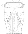
本発明に係る電気かみそりは、本体ケース2とかみそりヘッド3との間に、かみそりヘッド3を左右傾動可能に支持する左右傾動機構が設けてある。図1に示すように、左右傾動機構は、かみそりヘッド3が仮想傾動中心Pの回りに左右傾動できるように構成してある。かみそりヘッド3は、左右傾動機構とかみそりヘッド3との間に設けたフロート構造で上下動可能に案内支持されてフロートばね80で押し上げ付勢されている。以て、本体ケース2側へ押し込み操作されるかみそりヘッド3の押し込み量に応じて、仮想傾動中心Pとかみそりヘッド3の刃面Sとの上下距離Hが大小に変化することを特徴とする電気かみそり。   The electric razor according to the present invention is provided with a left-right tilt mechanism that supports the razor head 3 so as to be tiltable left and right between the main body case 2 and the razor head 3. As shown in FIG. 1, the left / right tilt mechanism is configured such that the razor head 3 can tilt left / right around the virtual tilt center P. The razor head 3 is guided and supported by a float structure provided between the left-right tilt mechanism and the razor head 3 so as to be movable up and down, and is pushed up and biased by a float spring 80. Thus, the vertical distance H between the virtual tilt center P and the blade surface S of the razor head 3 varies depending on the pushing amount of the razor head 3 pushed into the main body case 2 side. Razor.

左右傾動機構は、本体ケース2側に固定されるブラケット51と、ブラケット51で左右傾動可能に支持されるヘッドホルダー52と、ヘッドホルダー52を中立位置へ復帰操作する第1復帰ばね53を含んで構成し、かみそりヘッド3をヘッドホルダー52で上下動可能に案内支持する。   The left / right tilt mechanism includes a bracket 51 fixed to the main body case 2 side, a head holder 52 supported by the bracket 51 so as to be tiltable left / right, and a first return spring 53 for returning the head holder 52 to a neutral position. The razor head 3 is guided and supported by the head holder 52 so as to be movable up and down.

左右傾動機構の仮想傾動中心Pは、かみそりヘッド3の頂部中央Qの近傍に位置させる。   The virtual tilt center P of the left / right tilt mechanism is positioned in the vicinity of the top center Q of the razor head 3.

図4に示すように、かみそりヘッド3に、外刃15と、外刃15を支持する外刃支持構造13と、内刃16と、内刃16を押し上げ付勢する内刃ばね28とを設ける。外刃15は外刃支持構造13で上下動および左右傾動可能に支持する。   As shown in FIG. 4, the razor head 3 is provided with an outer blade 15, an outer blade support structure 13 that supports the outer blade 15, an inner blade 16, and an inner blade spring 28 that pushes up and biases the inner blade 16. . The outer blade 15 is supported by the outer blade support structure 13 so as to be movable up and down and tilted left and right.

外刃支持構造13は、外刃15を支持する傾動枠31と、傾動枠31を支持する外刃ホルダー32とを含んで構成する。傾動枠31は、外刃ホルダー32に設けた左右一対の側壁43で軸36を介して前後傾動可能に支持する。傾動枠31と外刃ホルダー32との間に、傾動枠31を中立位置へ復帰付勢する第2復帰ばね37を設ける。   The outer blade support structure 13 includes a tilt frame 31 that supports the outer blade 15 and an outer blade holder 32 that supports the tilt frame 31. The tilt frame 31 is supported by a pair of left and right side walls 43 provided on the outer blade holder 32 so as to be tiltable back and forth via a shaft 36. A second return spring 37 is provided between the tilt frame 31 and the outer blade holder 32 to urge the tilt frame 31 back to the neutral position.

図3に示すように、かみそりヘッド3に前後一対の外刃15と、各外刃15に沿って往復駆動される内刃16とを組み付ける。以て、両内刃16を往復駆動する内刃駆動構造を、前側の内刃16と後側の内刃16とを互いに逆向きに駆動できるように構成する。   As shown in FIG. 3, a pair of front and rear outer blades 15 and an inner blade 16 that is driven to reciprocate along each outer blade 15 are assembled to the razor head 3. Thus, the inner blade drive structure that reciprocally drives both the inner blades 16 is configured such that the front inner blade 16 and the rear inner blade 16 can be driven in opposite directions.

左右傾動機構は、ヘッドホルダー52の前後面の少なくともいずれか一方に形成される部分凹弧状の傾動溝70と、ブラケット51で遊転自在に軸支されて、前記傾動溝70を移行案内する複数個のガイドローラー59を含んで構成する(図1参照)。   The left / right tilting mechanism is supported by a partially concave arc-shaped tilting groove 70 formed on at least one of the front and rear surfaces of the head holder 52 and a bracket 51 so as to be freely swingable, and a plurality of the tilting mechanisms 70 are moved and guided. A single guide roller 59 is included (see FIG. 1).

ブラケット51に、2個のガイドローラー59と補助ローラー61とを設ける。ヘッドホルダー52の傾動溝70に隣接して、前記補助ローラー61で移行案内される部分円弧状の傾動体71を設ける。   Two guide rollers 59 and an auxiliary roller 61 are provided on the bracket 51. A partial arcuate tilting body 71 is provided adjacent to the tilting groove 70 of the head holder 52 and guided by the auxiliary roller 61.

ブラケット51とヘッドホルダー52との間に、左右傾動したヘッドホルダー52を中立位置へ復帰操作する第1復帰ばね53を設ける(図8参照)。   A first return spring 53 is provided between the bracket 51 and the head holder 52 to return the head holder 52 tilted left and right to the neutral position (see FIG. 8).

内刃ばね28のばね力をF1、フロートばね80のばね力をF2、第2復帰ばね37のばね力をF3、第1復帰ばね53のばね力をF4とするとき、各ばねのばね力がF1>F2>F3>F4の関係を満足するように設定する。   When the spring force of the inner blade spring 28 is F1, the spring force of the float spring 80 is F2, the spring force of the second return spring 37 is F3, and the spring force of the first return spring 53 is F4, the spring force of each spring is It sets so that the relationship of F1> F2> F3> F4 may be satisfied.

本発明の電気かみそりは、かみそりヘッド3を左右傾動機構で、ひとつの仮想傾動中心Pの回りに左右傾動可能に支持し、さらに、左右傾動機構とかみそりヘッド3との間に設けたフロート構造で上下動可能に案内支持して、フロートばね80で押し上げ付勢した。これにより、本体ケース2側へ押し込み操作されるかみそりヘッド3の押し込み量に応じて、仮想傾動中心Pとかみそりヘッド3の刃面との上下距離Hを大小に変化させるようにした。   The electric razor of the present invention has a float structure in which the razor head 3 is supported by a left-right tilt mechanism so that it can tilt left and right around one virtual tilt center P, and is further provided between the left-right tilt mechanism and the razor head 3. It was guided and supported so that it could move up and down, and was pushed up and biased by a float spring 80. As a result, the vertical distance H between the virtual tilt center P and the blade surface of the razor head 3 is changed to be larger or smaller in accordance with the push amount of the razor head 3 pushed into the main body case 2 side.

上記のように、かみそりヘッド3の押し込み量に応じて、仮想傾動中心Pとかみそりヘッド3の刃面Sとの上下距離Hを大小に変化させる電気かみそりによれば、かみそりヘッド3の傾動姿勢を上下距離Hの範囲内で多様に変化させることができる。例えば、図13(a)に示すように仮想傾動中心Pが刃面Sの頂部中央Qに設けてある場合には、仮想傾動中心Pの回りにかみそりヘッド3を左右傾動でき、さらに、図13(b)に示すように刃面Sが仮想傾動中心Pから上下距離Hだけ沈み込む状態では、任意の沈み込み位置において仮想傾動中心Pの回りにかみそりヘッド3を多様に左右傾動することができる。なお、仮想傾動中心Pの位置は、かみそりヘッド3が左右傾動し、あるいは上下フロートしても常に一定であって、その位置は変化しない。   As described above, according to the electric razor that changes the vertical distance H between the virtual tilt center P and the blade surface S of the razor head 3 in accordance with the amount of pressing of the razor head 3, the tilting posture of the razor head 3 is changed. Various changes can be made within the range of the vertical distance H. For example, when the virtual tilt center P is provided at the top center Q of the blade surface S as shown in FIG. 13A, the razor head 3 can be tilted left and right around the virtual tilt center P. Further, FIG. In the state where the blade surface S sinks from the virtual tilt center P by the vertical distance H as shown in (b), the razor head 3 can be tilted in various directions around the virtual tilt center P at an arbitrary sink position. . Note that the position of the virtual tilt center P is always constant even when the razor head 3 tilts left or right or floats up and down, and the position does not change.

したがって、本発明の電気かみそりによれば、かみそりヘッド3の刃面Sを肌面に軽く当てた状態では、肌面の変化に追随してかみそりヘッド3を仮想傾動中心Pの回りに左右傾動させてひげ切断を円滑に行なうことができる。また、刃面Sが仮想傾動中心Pよりも下方へ沈み込んだ状態では、刃面Sの頂部中央Qが仮想傾動中心Pを中心とする半径線Rに沿って傾動変位し、このときの刃面Sは肌面に対して相対摺動しながら傾動する。そのため、かみそりヘッド3は、刃面Sが肌面に対して相対摺動するときの摩擦抵抗によって動きが抑止されることになり、かみそりヘッド3はふらつくこともなく安定した状態で肌面の変化に従って傾動変位し、より軽快にひげ切断を行える。また、刃面Sの沈み込み量の違いに応じて傾動モーメントが大小に変化するので、上下距離Hが小さい場合にはかみそりヘッド3は動きやすい状態にあるが、上下距離Hが大きい場合には動きが抑止された状態になり、使用者は刃面Sを好みの押圧力で肌面に押し付けて左右傾動させることができる。   Therefore, according to the electric razor of the present invention, when the blade surface S of the razor head 3 is lightly applied to the skin surface, the razor head 3 is tilted left and right around the virtual tilt center P following the change of the skin surface. The beard cutting can be performed smoothly. Further, when the blade surface S sinks below the virtual tilt center P, the top center Q of the blade surface S is tilted and displaced along the radial line R centering on the virtual tilt center P, and the blade at this time The surface S tilts while sliding relative to the skin surface. Therefore, the movement of the razor head 3 is restrained by the frictional resistance when the blade surface S slides relative to the skin surface, and the razor head 3 does not wobble and changes in the skin surface in a stable state. In accordance with the displacement, the whisker can be cut more easily. Further, since the tilting moment changes depending on the amount of subsidence of the blade surface S, the razor head 3 is easy to move when the vertical distance H is small, but when the vertical distance H is large. The movement is suppressed, and the user can press the blade surface S against the skin surface with a desired pressing force to tilt left and right.

ブラケット51と、ブラケット51で左右傾動可能に支持されるヘッドホルダー52と、第1復帰ばね53などで左右傾動機構を構成し、かみそりヘッド3をヘッドホルダー52上下動可能に案内支持する浮動支持構造によれば、ヘッドホルダー52およびかみそりヘッド3を左右傾動させながら、同時にかみそりヘッド3を上下フロートすることができる。また、ブラケット51でヘッドホルダー52を左右傾動可能に支持し、ヘッドホルダー52でかみそりヘッド3を上下動可能に案内支持するので、左右傾動動作と上下動動作をそれぞれ独立して円滑に行なうことができ、したがって、刃面Sを肌面の変化に追随して左右傾動しながら上下フロートさせてかみそりヘッド3を最適の姿勢に維持し、軽快にひげ切断を行える。   The bracket 51, the head holder 52 supported by the bracket 51 so as to be able to tilt left and right, and the first return spring 53 and the like constitute a left-right tilt mechanism, and the floating support structure that guides and supports the razor head 3 so that the head holder 52 can move up and down. According to the above, while the head holder 52 and the razor head 3 are tilted left and right, the razor head 3 can be floated up and down at the same time. Further, since the head holder 52 is supported by the bracket 51 so as to be able to tilt left and right, and the razor head 3 is guided and supported by the head holder 52 so as to be able to move up and down, the left and right tilting operation and the vertical movement operation can be performed independently and smoothly. Therefore, the razor head 3 can be floated up and down while tilting left and right following the change in the skin surface to maintain the razor head 3 in an optimal posture, and the beard can be cut lightly.

左右傾動機構の仮想傾動中心Pが、かみそりヘッド3の頂部中央Qの近傍に位置させてあると、かみそりヘッド3を肌面に押し付けた状態における仮想傾動中心Pを、刃面Sの外面上方に位置させることができる。このように、仮想傾動中心Pが刃面Sの外面上方に位置する状態の刃面Sは、仮想傾動中心Pを中心とする半径線Rに沿って傾動変位し、肌面に押し付けられている側の刃面Sが下り傾斜する状態で傾動する。この状態でかみそりヘッド3の全体を上方スライドすると、先の傾動姿勢を維持した状態のままで刃面Sを肌面に対して適正に密着させてひげ切断を行える。したがって、仮想傾動中心Pが刃面Sより本体ケース2側に設けてある場合に比べて、より安定した状態で刃面Sを肌面の変化に従って傾動変位させながら軽快にひげ切断を行える。   When the virtual tilt center P of the left / right tilt mechanism is positioned in the vicinity of the top center Q of the razor head 3, the virtual tilt center P when the razor head 3 is pressed against the skin surface is positioned above the outer surface of the blade surface S. Can be positioned. Thus, the blade surface S in a state where the virtual tilt center P is located above the outer surface of the blade surface S is tilted and displaced along the radial line R centering on the virtual tilt center P and is pressed against the skin surface. The side blade surface S tilts in a state where it is inclined downward. When the entire razor head 3 is slid upward in this state, whiskers can be cut while the blade surface S is properly brought into close contact with the skin surface while maintaining the previously tilted posture. Therefore, as compared with the case where the virtual tilt center P is provided on the main body case 2 side with respect to the blade surface S, whiskers can be cut lightly while the blade surface S is tilted and displaced according to the skin surface change in a more stable state.

外刃15、外刃支持構造13、内刃16、および内刃16を押し上げ付勢する内刃ばね28をかみそりヘッド3に設け、外刃15を外刃支持構造13で上下動および左右傾動可能に支持すると、質量が小さな外刃15をかみそりヘッド3などの他の部材に先行して上下動させ、あるいは左右傾動させて、刃面Sの姿勢を肌面の変化に対応して小刻みに、しかも軽快に追随させることができる。   The razor head 3 is provided with an outer blade 15, an outer blade support structure 13, an inner blade 16, and an inner blade spring 28 that pushes and urges the inner blade 16, and the outer blade 15 can be moved up and down and tilted left and right by the outer blade support structure 13. , The outer blade 15 having a small mass is moved up and down or tilted left and right in advance of other members such as the razor head 3, and the posture of the blade surface S is gradually changed corresponding to the change in the skin surface. Moreover, it can be followed lightly.

傾動枠31、および外刃ホルダー32などで外刃支持構造13を構成し、傾動枠31を外刃ホルダー32で軸36を介して前後傾動可能に支持し、第2復帰ばね37で中立位置へ復帰付勢すると、先に説明したように外刃15を肌面の変化に対応して上下動および左右傾動可能としながら、さらに前後傾動させることができる。したがって、刃面Sを肌面に常に適正な姿勢で密着させて、効果的にひげ切断を行える。   The outer blade support structure 13 is configured by the tilt frame 31 and the outer blade holder 32, and the tilt frame 31 is supported by the outer blade holder 32 so as to be tiltable forward and backward via the shaft 36, and is moved to the neutral position by the second return spring 37. When the return bias is applied, the outer blade 15 can be further tilted back and forth while allowing the outer blade 15 to move up and down and to the left and right according to changes in the skin surface as described above. Therefore, the blade surface S is always brought into close contact with the skin surface in an appropriate posture, and the beard cutting can be performed effectively.

かみそりヘッド3に前後一対の外刃15と、往復駆動される前後一対の内刃16とが設けてある場合に、両内刃16を内刃駆動構造で互いに逆向きに駆動すると、各内刃16の運動慣性力を打ち消しあうことができ、例えば両内刃16が同じ向きに同時に駆動される場合に比べて、振動の発生を著しく抑止して電気かみそりを静音化でき、使用感を向上できる。また、外刃15が往復振動を受けて肌面から浮き離れるのをよく防止できる。   When the razor head 3 is provided with a pair of front and rear outer blades 15 and a pair of front and rear inner blades 16 that are driven to reciprocate, when the inner blades 16 are driven in opposite directions by the inner blade driving structure, each inner blade The motion inertia force of 16 can be canceled out, for example, compared with the case where both the inner blades 16 are simultaneously driven in the same direction, the generation of vibration can be remarkably suppressed and the electric razor can be silenced, and the feeling of use can be improved. . Further, it is possible to well prevent the outer blade 15 from being lifted away from the skin surface due to reciprocal vibration.

ヘッドホルダー52の前後面の少なくともいずれか一方に形成される部分凹弧状の傾動溝70と、ブラケット51の側に設けられる複数個のガイドローラー59などで左右傾動機構を構成すると、複数個のガイドローラー59で傾動溝70を常に安定した状態で確実に傾動案内することができる。つまり、左右傾動機構を確動機構として構成して、ヘッドホルダー52をガイドローラー59で規定される移動軌跡に従って的確に傾動変位させることができる。   When a left and right tilt mechanism is configured by a partially concave arc-shaped tilt groove 70 formed on at least one of the front and rear surfaces of the head holder 52 and a plurality of guide rollers 59 provided on the bracket 51 side, a plurality of guides are provided. The roller 59 can reliably guide the tilting groove 70 in a stable state. That is, the left / right tilt mechanism can be configured as a positive mechanism, and the head holder 52 can be accurately tilted and displaced according to the movement locus defined by the guide roller 59.

ブラケット51に、2個のガイドローラー59と補助ローラー61とを設け、これらのローラー59・61で傾動溝70および傾動体71を移行案内すると、ヘッドホルダー52を3個のローラー59・61でさらに安定した状態で左右傾動可能に支持できる。また、かみそりヘッド3がフロートばね80に抗して押し込み操作されるときの外力を、3個のローラー59・61で分散支持して、ヘッドホルダー52の左右傾動を軽快かつ円滑に行なうことができる。   When two guide rollers 59 and an auxiliary roller 61 are provided on the bracket 51 and the tilt groove 70 and the tilt body 71 are moved and guided by these rollers 59 and 61, the head holder 52 is further moved by the three rollers 59 and 61. It can be supported so that it can tilt to the left and right in a stable state. Further, the external force when the razor head 3 is pushed against the float spring 80 can be dispersedly supported by the three rollers 59 and 61 so that the head holder 52 can be tilted left and right lightly and smoothly. .

左右傾動したヘッドホルダー52を中立位置へ復帰操作する第1復帰ばね53を、相対摺動するブラケット51とヘッドホルダー52との間に設けると、第1復帰ばね53のばね力を遅滞なくヘッドホルダー52に作用させて、ヘッドホルダー52およびかみそりヘッド3の中立位置への復帰動作を円滑に行なうことができる。また、第1復帰ばね53がいたずらに大形化するのを防止して、浮動支持構造をコンパクトにまとめることにも役立つ。   If the first return spring 53 for returning the head holder 52 tilted left and right to the neutral position is provided between the bracket 51 and the head holder 52 that slide relative to each other, the spring force of the first return spring 53 is maintained without delay. Thus, the head holder 52 and the razor head 3 can be smoothly returned to the neutral position. Further, it is possible to prevent the first return spring 53 from being unnecessarily large and to make the floating support structure compact.

内刃ばね28のばね力をF1、フロートばね80のばね力をF2、第2復帰ばね37のばね力をF3、第1復帰ばね53のばね力をF4とするとき、各ばねのばね力をF1>F2>F3>F4の関係を満足するように設定すると、自由度が多岐にわたるかみそりヘッド3において、外刃15やかみそりヘッド3の動きを抑制して安定した状態でひげ剃りを行なえる。詳しくは、他に先行して外刃15を上下動および左右傾動させ、次いで、かみそりヘッド3を本体ケース2側へ沈み込み移動することができる。また、外刃15および内刃16の前後傾動を許す状態を経て、かみそりヘッド3を左右に傾動変位させることができる。なお、各ばねのばね力は、外刃15が上下動および左右傾動を開始するとき、かみそりヘッド3が沈み込みを開始するとき、外刃15および内刃16が前後傾動を開始するとき、かみそりヘッド3が左右傾動を開始するときのばね力である。   When the spring force of the inner blade spring 28 is F1, the spring force of the float spring 80 is F2, the spring force of the second return spring 37 is F3, and the spring force of the first return spring 53 is F4, the spring force of each spring is When setting is made so as to satisfy the relationship of F1> F2> F3> F4, in the razor head 3 having various degrees of freedom, the movement of the outer blade 15 and the razor head 3 can be suppressed and shaving can be performed in a stable state. Specifically, the outer blade 15 can be moved up and down and tilted left and right prior to the others, and then the razor head 3 can be moved into the main body case 2 by sinking. Further, the razor head 3 can be tilted and displaced to the left and right after allowing the outer blade 15 and the inner blade 16 to tilt forward and backward. The spring force of each spring is such that when the outer blade 15 starts to move up and down and to the left and right, when the razor head 3 starts to sink, and when the outer blade 15 and the inner blade 16 start to tilt back and forth, This is the spring force when the head 3 starts to tilt left and right.

(実施例) 図1ないし図13は本発明に係る電気かみそりの実施例を示す。図2において電気かみそりは、グリップを兼ねる本体ケース2と、本体ケース2の内部に収容される電装部と、本体ケース2の上部に配置されるかみそりヘッド3などで構成する。電装部は2次電池4と、制御回路が実装された回路基板と、これら両者を収容する内ケース5と、スイッチ構造などで構成する。内ケース5は本体ケース2に固定してある。本体ケース2の前面には、モーター起動用のスイッチノブ6と、電気かみそりの運転状況および2次電池4の充電状況を点灯表示する表示窓7が設けてある。なお、本発明における前後、左右、上下とは、図2および図3に示す直交する矢印と前後、左右、上下の表示に従うものとする。 (Embodiment) FIGS. 1 to 13 show an embodiment of an electric shaver according to the present invention. In FIG. 2, the electric razor is composed of a main body case 2 that also serves as a grip, an electrical component housed in the main body case 2, a razor head 3 disposed on the upper portion of the main body case 2, and the like. The electrical component includes a secondary battery 4, a circuit board on which a control circuit is mounted, an inner case 5 that accommodates both, a switch structure, and the like. The inner case 5 is fixed to the main body case 2. On the front surface of the main body case 2, a switch knob 6 for starting the motor and a display window 7 for lighting and displaying the operation status of the electric razor and the charging status of the secondary battery 4 are provided. In the present invention, “front / rear”, “left / right”, and “upper / lower” refer to the orthogonal arrows shown in FIG. 2 and FIG.

かみそりヘッド3は、ヘッドケース11と、ヘッドケース11の下面に固定されるモーターホルダー12と、ヘッドケース11の上面に組み付けられる外刃支持構造13などを主な外郭構造体にして構成してある。かみそりヘッド3の上端には、網刃からなる前後一対の外刃15と、外刃15の内面に沿って往復駆動されるスリット刃からなる一対の内刃16とが配置してある。外刃15は上下面が開口する外刃枠17に固定されてカセット化してある。同様に、内刃16は上下面が開口する内刃枠18に固定されてカセット化してある。図4に示すように、外刃枠17の左右側壁には、上下方向に長いスライド溝19が形成してある。内刃枠18の内部の左右中央には、後述する駆動軸24を連結するための受動片20が一体に設けてある。   The razor head 3 includes a head case 11, a motor holder 12 fixed to the lower surface of the head case 11, an outer blade support structure 13 assembled on the upper surface of the head case 11, and the like as main outer structures. . At the upper end of the razor head 3, a pair of front and rear outer blades 15 made of mesh blades and a pair of inner blades 16 made of slit blades reciprocally driven along the inner surface of the outer blade 15 are arranged. The outer cutter 15 is fixed to an outer cutter frame 17 whose upper and lower surfaces are open and is formed into a cassette. Similarly, the inner blade 16 is fixed to an inner blade frame 18 whose upper and lower surfaces are open and is formed into a cassette. As shown in FIG. 4, slide grooves 19 that are long in the vertical direction are formed on the left and right side walls of the outer cutter frame 17. A passive piece 20 for connecting a drive shaft 24 to be described later is integrally provided at the left and right center inside the inner blade frame 18.

かみそりヘッド3の内部には、両内刃16を往復駆動する内刃駆動構造が組み込んである。図3に示すように内刃駆動構造は、モーターホルダー12の内部に組み込まれるモーター22と、ヘッドケース11の内部に組み込まれる前後一対の振動子23と、振動子23の往復動力を内刃16へ伝動する前後一対の駆動軸24などで構成する。   Inside the razor head 3, an inner blade driving structure for reciprocally driving both inner blades 16 is incorporated. As shown in FIG. 3, the inner blade drive structure has a motor 22 incorporated in the motor holder 12, a pair of front and rear vibrators 23 incorporated in the head case 11, and the reciprocating power of the vibrator 23 to the inner blade 16. It comprises a pair of front and rear drive shafts 24 that transmit to the front.

モーター22の出力軸には偏心カム25が固定してあり、偏心カム25の上下には、振動子23を往復駆動する偏心ピン26が設けてある。前側の内刃16と後側の内刃16とを互いに逆向きに駆動するために、上下の偏心ピン26の位相位置は180度ずらしてある。駆動軸24は、振動子23に連結されるT字状の固定駆動軸24aと、固定駆動軸24aに対して前後傾動できる可動駆動軸24bとで構成する。可動駆動軸24bの上部に、先の受動片20と係合する連結枠27が一体に形成してある。連結枠27に連結した状態の内刃16は、受動片20と可動駆動軸24bとの間に配置した内刃ばね28で押し上げ付勢する。   An eccentric cam 25 is fixed to the output shaft of the motor 22, and eccentric pins 26 for reciprocating the vibrator 23 are provided above and below the eccentric cam 25. In order to drive the front inner blade 16 and the rear inner blade 16 in opposite directions, the phase positions of the upper and lower eccentric pins 26 are shifted by 180 degrees. The drive shaft 24 includes a T-shaped fixed drive shaft 24a connected to the vibrator 23 and a movable drive shaft 24b that can be tilted back and forth with respect to the fixed drive shaft 24a. A connecting frame 27 that engages with the passive piece 20 is formed integrally with the upper portion of the movable drive shaft 24b. The inner blade 16 connected to the connection frame 27 is pushed up and biased by an inner blade spring 28 disposed between the passive piece 20 and the movable drive shaft 24b.

図6に示すようにヘッドケース11は、上ヘッドケース11aと下ヘッドケース11bとで構成してあり、これら両ケース11a・11bの接合面の間に振動子23の両側端の取付部が挟み固定される。外刃支持構造13は、外刃枠17を支持する傾動枠31と、傾動枠31を支持する外刃ホルダー32と、これら両者31・32の間に配置されるばね受け枠33とで構成する。傾動枠31は、外刃15および外刃枠17を上下動および左右傾動可能に支持し、さらに外刃15および外刃枠17を前後傾動可能とするために設けてある。   As shown in FIG. 6, the head case 11 is composed of an upper head case 11a and a lower head case 11b, and attachment portions on both ends of the vibrator 23 are sandwiched between the joint surfaces of the both cases 11a and 11b. Fixed. The outer blade support structure 13 includes a tilting frame 31 that supports the outer blade frame 17, an outer blade holder 32 that supports the tilting frame 31, and a spring receiving frame 33 that is disposed between the both 31 and 32. . The tilt frame 31 is provided to support the outer blade 15 and the outer blade frame 17 so as to be movable up and down and to the left and right, and to allow the outer blade 15 and the outer blade frame 17 to tilt forward and backward.

詳しくは、傾動枠31の左右一対の側壁の対向面に係合突起35を形成し、両側壁の間に配置した外刃枠17のスライド溝19を係合突起35でスライド案内することにより、外刃15および外刃枠17を上下動および左右傾動可能に支持している(図4参照)。また、傾動枠31の左右側壁の上部を、外刃ホルダー32に軸36を介して前後傾動可能に軸支して、外刃15および外刃枠17を傾動枠31に同行して前後傾動できるようにしている。   Specifically, by forming engagement protrusions 35 on the opposing surfaces of the pair of left and right side walls of the tilting frame 31, and slidingly guiding the slide grooves 19 of the outer blade frame 17 disposed between both side walls with the engagement protrusions 35, The outer blade 15 and the outer blade frame 17 are supported so as to be vertically movable and horizontally tiltable (see FIG. 4). Further, the upper portions of the left and right side walls of the tilting frame 31 are pivotally supported by the outer blade holder 32 via the shaft 36 so as to tilt forward and backward, and the outer blade 15 and the outer blade frame 17 can be tilted forward and backward by accompanying the tilting frame 31. I am doing so.

傾動枠31と外刃ホルダー32との間には第2復帰ばね37が配置してあり、このばね37で前後傾動した傾動枠31を中立位置へ復帰操作する。図5に示すように第2復帰ばね37は、部分円弧状の線ばねからなり、その前後端がばね受け枠33および外刃ホルダー32に設けた溝38に掛止してある。ばね受け枠33には、第2復帰ばね37の中途部を挟み保持する上下一対のばね保持体39・40が設けてある。ばね受け枠33が傾動枠31に同行して前後傾動するとき、ばね保持体39・40は第2復帰ばね37と相対摺動しながら同ばね37を弾性変形させ、片方の掛止端を溝38に沿って変位させる。このときの弾性力で傾動枠31および外刃枠17を中立位置へ復帰させる。傾動枠31の前後傾動を円滑化するために、左右側壁の外面に前後一対の傾動ピン42を突設し、両ピン42を外刃ホルダー32の側壁43に設けた半円状のガイド溝44で移行案内している。   A second return spring 37 is disposed between the tilt frame 31 and the outer blade holder 32, and the tilt frame 31 tilted back and forth by this spring 37 is returned to the neutral position. As shown in FIG. 5, the second return spring 37 is a partial arc-shaped wire spring, and the front and rear ends thereof are hooked in grooves 38 provided in the spring receiving frame 33 and the outer blade holder 32. The spring receiving frame 33 is provided with a pair of upper and lower spring holders 39 and 40 that sandwich and hold the middle part of the second return spring 37. When the spring receiving frame 33 accompanies the tilting frame 31 and tilts back and forth, the spring holders 39 and 40 elastically deform the spring 37 while sliding relative to the second return spring 37, and the one latching end is grooved. 38 is displaced. The tilting frame 31 and the outer blade frame 17 are returned to the neutral position by the elastic force at this time. In order to facilitate the tilting of the tilting frame 31 in the front-rear direction, a pair of front and rear tilting pins 42 are provided on the outer surfaces of the left and right side walls. I have been guiding the transition.

外刃ホルダー32は、左右一対の側壁43を有する上下面が開口する枠体からなり、ヘッドケース11に対して着脱可能に装着してある。一対の側壁43の間に傾動枠31が配置され、先に説明したように軸36で前後傾動可能に支持してある。図7に示すように、外刃ホルダー32は、ヘッドケース11に組み込んだロック爪45で分離不能にロック保持してある。ロック爪45と一体に形成したロック解除ボタン46をロックばね47に抗して押し込み操作することにより、ロック爪45とロック凹部48との係合を解除して、外刃ホルダー32をヘッドケース11から取り外すことができる。   The outer blade holder 32 is formed of a frame body having upper and lower surfaces having a pair of left and right side walls 43 and is detachably attached to the head case 11. The tilt frame 31 is disposed between the pair of side walls 43 and is supported by the shaft 36 so as to be tiltable back and forth as described above. As shown in FIG. 7, the outer blade holder 32 is locked and held so as not to be separated by a lock claw 45 incorporated in the head case 11. The lock release button 46 formed integrally with the lock claw 45 is pushed against the lock spring 47 to release the engagement between the lock claw 45 and the lock recess 48, so that the outer blade holder 32 is moved to the head case 11. Can be removed from.

かみそりヘッド3の全体を左右傾動可能に支持するために、本体ケース2とかみそりヘッドと3の間に左右傾動機構を設けている。また、左右傾動機構とかみそりヘッド3との間にフロート構造を設けて、かみそりヘッド3の全体を上下フロート可能に支持している。   In order to support the entire razor head 3 so as to be able to tilt left and right, a left-right tilt mechanism is provided between the main body case 2 and the razor head 3. Further, a float structure is provided between the left-right tilt mechanism and the razor head 3, and the entire razor head 3 is supported so as to be able to float up and down.

図1において左右傾動機構は、内ケース5の上端に締結固定されるブラケット51と、ブラケット51で左右傾動可能に支持されるヘッドホルダー52と、ヘッドホルダー52を中立位置へ復帰操作する第1復帰ばね53(図8参照)などで構成する。ブラケット51は、前ブラケット54と後ブラケット55の下端どうしをビス56で締結してU字枠状に形成してある。図9に示すように前ブラケット54の上部にはT字状のローラーアーム58が設けてあり、ローラーアーム58の両横腕の後面側に左右一対のガイドローラー59をピン60で遊転自在に軸支する。さらにローラーアーム58の縦腕の中途部前面に、別の補助ローラー61をピン62で遊転自在に軸支する。後ブラケット55の上部前面に、さらに別の補助ローラー63をピン64で遊転自在に軸支する。第1復帰ばね53は引っ張りばねからなり、その上下端はピン64と後述するばね掛突起75とに掛止してある(図8参照)。   In FIG. 1, the left / right tilt mechanism includes a bracket 51 fastened and fixed to the upper end of the inner case 5, a head holder 52 supported by the bracket 51 so as to be tiltable left and right, and a first return for returning the head holder 52 to a neutral position. A spring 53 (see FIG. 8) is used. The bracket 51 is formed in a U-shaped frame shape by fastening lower ends of the front bracket 54 and the rear bracket 55 with screws 56. As shown in FIG. 9, a T-shaped roller arm 58 is provided on the upper portion of the front bracket 54, and a pair of left and right guide rollers 59 can be freely rotated by pins 60 on the rear surface side of both lateral arms of the roller arm 58. Pivot. Further, another auxiliary roller 61 is pivotally supported by a pin 62 on the front surface of the middle portion of the vertical arm of the roller arm 58 so as to be freely rotatable. A further auxiliary roller 63 is pivotally supported by a pin 64 on the upper front surface of the rear bracket 55 so as to be freely rotatable. The first return spring 53 is composed of a tension spring, and the upper and lower ends thereof are hooked on a pin 64 and a spring hooking protrusion 75 described later (see FIG. 8).

ヘッドホルダー52は、それぞれ樋体状に形成される前ホルダー体67と後ホルダー体68とで構成する。前ホルダー体67の前面上部には、ガイドローラー59で移行案内される部分凹弧状の前傾動溝(傾動溝)70が形成してあり、さらに前傾動溝70の下側に補助ローラー61で移行案内される部分凹弧状の傾動枠71が設けてある。前ホルダー体67の後面には、モーターホルダー12をスライド自在に案内支持する前ガイド面72(図11参照)が樋溝状に凹み形成してある。   The head holder 52 includes a front holder body 67 and a rear holder body 68 each formed in a casing shape. The front holder body 67 has a partially concave arc-shaped forward tilt groove (tilt groove) 70 which is guided to be transferred by the guide roller 59, and is further moved by the auxiliary roller 61 below the front tilt groove 70. A partially concave arc-shaped tilting frame 71 to be guided is provided. On the rear surface of the front holder body 67, a front guide surface 72 (see FIG. 11) for slidably guiding and supporting the motor holder 12 is formed in a groove shape.

後ホルダー体68の上部には、補助ローラー63で移行案内される部分凹弧状の後傾動溝(傾動溝)74が形成してあり、さらに後面の下端中央に第1復帰ばね53を掛止するためのばね掛突起75が形成してある。後ホルダー体68の前面には、モーターホルダー12をスライド自在に案内支持する後ガイド面76が樋溝状に凹み形成してある。図11に示すように、前後のホルダー体67・68は、モーターホルダー12を前後から抱持する状態で接合されてビス77で締結され、さらに断面コ字状の左右一対の挟持ばね78で締結してある(図12参照)。   In the upper part of the rear holder body 68, a rear concave groove (tilt groove) 74 that is partially guided by the auxiliary roller 63 is formed, and the first return spring 53 is latched at the center of the lower end of the rear surface. For this purpose, a spring projection 75 is formed. A rear guide surface 76 that slidably guides and supports the motor holder 12 is formed on the front surface of the rear holder body 68 so as to be recessed in a groove shape. As shown in FIG. 11, the front and rear holder bodies 67 and 68 are joined in a state of holding the motor holder 12 from the front and rear, fastened with screws 77, and further fastened with a pair of left and right sandwiching springs 78 having a U-shaped cross section. (See FIG. 12).

上記のように、モーターホルダー12をヘッドホルダー52で支持し、ヘッドホルダー52をブラケット51で支持することにより、かみそりヘッド3の全体を左右傾動可能に支持できる。かみそりヘッド3が左右傾動するときの仮想傾動中心Pは、前傾動溝70、傾動枠71、後傾動溝74の曲率によって決定され、この実施例では、図1に示すように仮想傾動中心Pがかみそりヘッド3の頂部中央Qに位置するように先の曲率を設定した。ヘッドホルダー52をブラケット51で支持した状態においては、前傾動溝70の上側の溝周面が左右のガイドローラー59で支持され、傾動枠71の上面が補助ローラー61で支持されている。したがって、ヘッドホルダー52が左右傾動し、あるいはかみそりヘッド3が上下フロートするとき、ヘッドホルダー52が上下にがたつくことはなく、左右傾動動作および上下フロート動作を円滑に行なえる。   As described above, by supporting the motor holder 12 with the head holder 52 and supporting the head holder 52 with the bracket 51, the entire razor head 3 can be supported so as to be tiltable in the left-right direction. The virtual tilt center P when the razor head 3 tilts left and right is determined by the curvature of the front tilt groove 70, the tilt frame 71, and the rear tilt groove 74. In this embodiment, as shown in FIG. The previous curvature was set so as to be located at the center Q of the top of the razor head 3. In a state where the head holder 52 is supported by the bracket 51, the upper groove circumferential surface of the front tilt groove 70 is supported by the left and right guide rollers 59, and the upper surface of the tilt frame 71 is supported by the auxiliary roller 61. Therefore, when the head holder 52 tilts left and right or the razor head 3 floats up and down, the head holder 52 does not rattle up and down, and the left and right tilting operation and the vertical floating operation can be performed smoothly.

フロート構造は、ヘッドホルダー52を利用して構成する。詳しくは、前後のホルダー体67・68に設けた前ガイド面72および後ガイド面76と、両ガイド面72・76でスライド案内されるモーターホルダー12と、フロートばね80とでフロート構造を構成する。フロートばね80は圧縮ばねからなり、モーターホルダー12の下端とブラケット51の基端との間に配置されて、かみそりヘッド3の全体を押し上げ付勢する。フロートばね80による押し上げ限界を規定するために、モーターホルダー12の下部の左右側面のそれぞれにストッパー81が形成してある。図10に示すように、ストッパー81がヘッドホルダー52の下端縁に接当した状態が先の押し上げ限界となる。   The float structure is configured using the head holder 52. Specifically, the front guide surface 72 and the rear guide surface 76 provided on the front and rear holder bodies 67 and 68, the motor holder 12 slidably guided by the both guide surfaces 72 and 76, and the float spring 80 constitute a float structure. . The float spring 80 is composed of a compression spring, and is disposed between the lower end of the motor holder 12 and the base end of the bracket 51 to push up and bias the entire razor head 3. In order to define the push-up limit by the float spring 80, stoppers 81 are formed on the left and right side surfaces of the lower part of the motor holder 12, respectively. As shown in FIG. 10, the state where the stopper 81 is in contact with the lower edge of the head holder 52 is the push-up limit.

以上のように構成した電気かみそりによれば、外刃15および内刃16が傾動枠31に対して上下動および左右傾動でき、傾動枠31は外刃ホルダー32に対して前後傾動できる。またかみそりヘッド3の全体が本体ケース2に対して上下フロートでき、しかも左右傾動できる。このように、かみそりヘッド3の自由度が多岐にわたると、かみそりヘッド3がふらつきやすくなる。そこで、先の自由度に強弱を与えて外刃15やかみそりヘッド3の動きを抑制し、安定した状態でひげ剃りを行なえるようにしている。具体的には、内刃ばね28のばね力をF1、フロートばね80のばね力をF2、第2復帰ばね37のばね力をF3、第1復帰ばね53のばね力をF4とするとき、各ばねのばね力がF1>F2>F3>F4の関係を満足するように設定している。   According to the electric shaver configured as described above, the outer blade 15 and the inner blade 16 can move up and down and left and right with respect to the tilt frame 31, and the tilt frame 31 can tilt back and forth with respect to the outer blade holder 32. Further, the entire razor head 3 can float up and down with respect to the main body case 2 and can tilt left and right. As described above, when the degrees of freedom of the razor head 3 are varied, the razor head 3 is likely to wobble. Therefore, the degree of freedom is given to the degree of freedom to suppress the movement of the outer blade 15 and the razor head 3 so that the shaving can be performed in a stable state. Specifically, when the spring force of the inner blade spring 28 is F1, the spring force of the float spring 80 is F2, the spring force of the second return spring 37 is F3, and the spring force of the first return spring 53 is F4, The spring force of the spring is set so as to satisfy the relationship of F1> F2> F3> F4.

不使用状態におけるかみそりヘッド3はフロートばね80で押し上げ付勢されて、図2に示すように、ヘッドケース11の周縁下面と本体ケース1の上端との間に充分な隙間が存在する状態になっている。この状態のかみそりヘッド3を、刃面(外刃15の外面)Sを水平に保持した状態のままで本体ケース2側へ押し込むと、フロートばね80が圧縮変形されて、やがてヘッドケース11の周縁下面が本体ケース1の上端で受け止められる。このときの、押し込み操作力はフロートばね80の反発力に一致する。   When the razor head 3 is not in use, the razor head 3 is pushed up and biased by the float spring 80, and as shown in FIG. 2, there is a sufficient gap between the lower peripheral surface of the head case 11 and the upper end of the main body case 1. ing. When the razor head 3 in this state is pushed into the main body case 2 while the blade surface (outer surface of the outer blade 15) S is held horizontally, the float spring 80 is compressed and deformed, and eventually the periphery of the head case 11 The lower surface is received by the upper end of the main body case 1. The pushing operation force at this time coincides with the repulsive force of the float spring 80.

かみそりヘッド3に刃面Sを傾動させる外力が作用していない無負荷状態で、かみそりヘッド3が中立位置にあるときの仮想傾動中心Pは、刃面Sの頂部中央Qに位置している。この状態から、かみそりヘッド3の刃面Sの頂部中央Qから左側へ離れた位置に外力が作用すると、図13(a)に示すように、かみそりヘッド3の全体が外力f1の大きさに応じて仮想傾動中心Pの回りに左傾動する。したがって、かみそりヘッド3の刃面Sを肌面に軽く当てた状態では、肌面の変化に追随してひげ切断を円滑に行なうことができる。この状態における第1復帰ばね53の反発力が、フロートばね80のばね力F2より小さいと、かみそりヘッド3が本体ケース2側へ沈み込むことはない。しかし、先の反発力がフロートばね80のばね力F2を越えると、超過分だけかみそりヘッド3が本体ケース2側へ沈み込む。   The virtual tilting center P when the razor head 3 is in the neutral position in an unloaded state where no external force that tilts the blade surface S is applied to the razor head 3 is located at the top center Q of the blade surface S. From this state, when an external force is applied to a position away from the top center Q of the blade surface S of the razor head 3 to the left side, as shown in FIG. 13A, the entire razor head 3 depends on the magnitude of the external force f1. To the left about the virtual tilt center P. Therefore, in a state where the blade surface S of the razor head 3 is lightly applied to the skin surface, the whisker can be cut smoothly following the change in the skin surface. If the repulsive force of the first return spring 53 in this state is smaller than the spring force F2 of the float spring 80, the razor head 3 will not sink into the main body case 2 side. However, when the previous repulsive force exceeds the spring force F2 of the float spring 80, the razor head 3 sinks to the main body case 2 side by an excess amount.

図13(b)に、かみそりヘッド3が外力f2で本体ケース2側の限界位置まで押し込まれ、さらに左傾動限界位置まで傾動した状態を示している。この状態では、従来の電気かみそりと同様に、フロートばね80の反発力と、第1復帰ばね53の反発力とが刃面Sに作用する。しかし、かみそりヘッド3が本体ケース2側へ押し込まれた分だけ、つまり上下距離Hの分だけ刃面Sが仮想傾動中心Pから沈み込む。そのため、刃面Sの頂部中央Qは、仮想傾動中心Pを中心とする半径線Rに沿って傾動変位することになり、その結果、刃面Sの頂部中央Qは肌面に対して相対摺動しながら傾動することになる。つまり、刃面Sが肌面に対して相対摺動する分だけ、かみそりヘッド3はふらつくこともなく、安定した状態で傾動変位できることになる。この作用は上下距離Hがゼロより大きい場合に発揮でき、上下距離Hが大きいほど顕著にあらわれることになる。   FIG. 13B shows a state in which the razor head 3 is pushed to the limit position on the main body case 2 side by the external force f2 and further tilted to the left tilt limit position. In this state, like the conventional electric razor, the repulsive force of the float spring 80 and the repulsive force of the first return spring 53 act on the blade surface S. However, the blade surface S sinks from the virtual tilt center P by the amount that the razor head 3 is pushed into the main body case 2 side, that is, the vertical distance H. Therefore, the top center Q of the blade surface S is tilted and displaced along the radial line R centered on the virtual tilt center P. As a result, the top center Q of the blade surface S is relatively slid relative to the skin surface. Tilt while moving. In other words, the razor head 3 does not fluctuate as much as the blade surface S slides relative to the skin surface, and can be tilted and displaced in a stable state. This effect can be exhibited when the vertical distance H is greater than zero, and becomes more prominent as the vertical distance H increases.

上記のように、上下距離Hがゼロより大きい場合に、刃面Sの頂部中央Qを肌面に対して相対摺動させながら傾動させると、本体ケース2側へ押し込まれた状態のかみそりヘッド3の左右方向のふらつきを防止できる。さらに、かみそりヘッド3の押し込み量が小さい場合と大きい場合とで、半径線Rに沿って移動する距離が大小に変化するので、使用者は好みの押し付け力を肌面に作用させながらより軽快にひげ切断を行えることになる。また、刃面Sの沈み込み量の違いに応じて傾動モーメントが大小に変化するので、上下距離Hが小さい場合にはかみそりヘッド3は比較的動きやすい状態にあるが、上下距離Hが大きい場合には動きが抑止された状態になり、使用者は刃面Sを好みの押圧力で肌面に押し付けて左右傾動させることができる。   As described above, when the vertical distance H is greater than zero, if the top center Q of the blade surface S is tilted while sliding relative to the skin surface, the razor head 3 is pushed into the body case 2 side. Can be prevented from wobbling in the left-right direction. Furthermore, since the distance moved along the radial line R varies depending on whether the amount of pushing of the razor head 3 is small or large, the user can lighten the user while applying the desired pressing force to the skin surface. A beard cutting can be performed. In addition, since the tilting moment changes depending on the amount of sinking of the blade surface S, the razor head 3 is relatively easy to move when the vertical distance H is small, but when the vertical distance H is large. In this state, the movement is suppressed, and the user can press the blade surface S against the skin surface with a desired pressing force and tilt it left and right.

因みに、刃面Sが本体ケース2側へ押し込まれて水平になっており、しかも頂部中央Qが下あごの下端に接当している場合に、電気かみそりの全体を図13に向かって左上側へ移動させると、それまで頂部中央Qに作用していた押し込み力が、左半分側の刃面Sに作用するため、かみそりヘッド3の全体は図13(b)に示すように、本体ケース2に対して左下がり状に傾動することになる。逆に、電気かみそりの全体を図13に向かって右上側へ移動させると、かみそりヘッド3の全体は、本体ケース2に対して右下がり状に傾動することになる。   Incidentally, when the blade surface S is pushed into the main body case 2 side and becomes horizontal, and the top center Q is in contact with the lower end of the lower jaw, the entire electric razor is shown in FIG. , The pushing force that had been acting on the top center Q until now acts on the blade surface S on the left half side, so that the entire razor head 3 is shown in FIG. Will tilt to the left. Conversely, when the entire electric razor is moved to the upper right side in FIG. 13, the entire razor head 3 tilts downward with respect to the main body case 2.

図14は、補助ローラー61のガイド構造の別実施例を示す。そこでは、前ホルダー体67の前面上部に、ガイドローラー59で移行案内される部分凹弧状の前傾動溝70を形成し、さらに前傾動溝70の下側に補助ローラー61で移行案内される部分凹弧状の傾動溝71を設けるようにした。傾動溝71は先の実施例における傾動枠に相当する。このように、補助ローラー61の案内対象は枠体であってもよいし、溝であってもよい。他は先の実施例と同じであるので、同じ部材に同じ符号を付してその説明を省略する。   FIG. 14 shows another embodiment of the guide structure of the auxiliary roller 61. There, a partial concave arc-shaped front tilt groove 70 guided by the guide roller 59 is formed in the front upper portion of the front holder body 67, and a portion guided by the auxiliary roller 61 below the front tilt groove 70. A concave arc-shaped tilting groove 71 is provided. The tilt groove 71 corresponds to the tilt frame in the previous embodiment. Thus, the guidance object of the auxiliary roller 61 may be a frame or a groove. Since others are the same as the previous embodiment, the same reference numerals are assigned to the same members, and descriptions thereof are omitted.

図15および図16は、本発明に係る電気かみそりの別実施例を示す。そこでは、左右傾動機構を内ケース5に固定されるブラケット51と、ブラケット51で左右一対の傾動アーム85を介して左右傾動可能に支持されるヘッドホルダー52と、第1復帰ばね53などで構成する。傾動アーム85の上端は、それぞれブラケット51の上端のアーム両端に連結ピン86を介して相対揺動可能に連結し、傾動アーム65の下端は、ヘッドホルダー52の左右に張り出したアームブラケット87の突端に連結ピン88を介して連結する。第1復帰ばね53は、先の実施例と同様にブラケット51とヘッドホルダー52との間に掛止する。   15 and 16 show another embodiment of the electric shaver according to the present invention. There, a left and right tilt mechanism is constituted by a bracket 51 fixed to the inner case 5, a head holder 52 supported by the bracket 51 via a pair of left and right tilt arms 85 so as to be tiltable left and right, a first return spring 53, and the like. To do. The upper end of the tilting arm 85 is connected to both ends of the upper end of the bracket 51 via a connecting pin 86 so as to be able to swing relative to each other, and the lower end of the tilting arm 65 is the protruding end of the arm bracket 87 protruding to the left and right of the head holder 52. Are connected to each other via a connecting pin 88. The first return spring 53 is hooked between the bracket 51 and the head holder 52 as in the previous embodiment.

かみそりヘッド3に刃面Sを傾動させる外力が作用していない無負荷状態で、かみそりヘッド3が中立位置にあるときの仮想傾動中心Pは、本体ケース2の中心軸線上で、刃面Sの頂部中央Qより下方のかみそりヘッド3の上下中途部に位置しており、左右の傾動アーム87の中心軸の交点になっている。この状態でかみそりヘッド3を押し込み操作すると、図15に想像線で示すように、かみそりヘッド3がフロートばね80に抗して本体ケース2側へ沈込む。   The virtual tilting center P when the razor head 3 is in the neutral position in the no-load state in which the external force for tilting the blade surface S is not applied to the razor head 3 is the center of the blade surface S on the central axis of the body case 2. It is located in the middle of the razor head 3 below the top center Q, and is the intersection of the central axes of the left and right tilt arms 87. When the razor head 3 is pushed in this state, the razor head 3 sinks toward the main body case 2 against the float spring 80, as shown by an imaginary line in FIG.

また、刃面Sが肌面に押し付けられて、その反力でかみそりヘッド3が左右いずれかの限界位置まで傾動した状態では、図16に示すように、反力を受けた側の刃面Sが下り傾斜する状態で傾動する。このときの、仮想傾動中心P1は、左右の傾動アーム87の中心軸線の交点上にあり、中立状態時の仮想傾動中心Pから図16へ向かって左側へずれた位置へ変位する。想像線で示すように、かみそりヘッド3が逆方向へ傾動する場合の仮想傾動中心P1は、同様に中立状態時の仮想傾動中心Pから図16へ向かって右側へずれた位置へ変位する。   Further, when the blade surface S is pressed against the skin surface and the razor head 3 is tilted to the left or right limit position by the reaction force, the blade surface S on the side subjected to the reaction force as shown in FIG. Tilts in a state of falling down. At this time, the virtual tilt center P1 is on the intersection of the central axes of the left and right tilt arms 87, and is displaced to a position shifted to the left from the virtual tilt center P in the neutral state toward FIG. As indicated by the imaginary line, the virtual tilt center P1 when the razor head 3 tilts in the opposite direction is similarly displaced from the virtual tilt center P in the neutral state to a position shifted to the right side in FIG.

上記のように、この実施例における仮想傾動中心Pの位置は、かみそりヘッド3が左右へ傾動するときの傾動角度の変化に応じて、瞬間的な仮想傾動中心Pの位置が連続して変化する。本発明は、このように瞬間的な仮想傾動中心Pが連続して変化する左右傾動構造をも含むこととする。   As described above, the position of the virtual tilt center P in this embodiment continuously changes according to the change in tilt angle when the razor head 3 tilts to the left and right. . The present invention also includes a left-right tilt structure in which the instantaneous virtual tilt center P changes continuously as described above.

上記の実施例以外に、かみそりヘッド3が左右傾動するときの仮想傾動中心Pは、かみそりヘッド3の頂部中央Qに位置させる必要はなく、図15および図16で説明したように頂部中央Qよりも本体ケース2側へ離れた位置に設ける以外に、頂部中央Qより上方へ離れた位置に設けることができる。本発明は、ロータリー式の内刃16を備えた電気かみそりにも適用できる。ブラケット51は本体ケース2に直接取り付けてあってもよい。   In addition to the above embodiment, the virtual tilt center P when the razor head 3 tilts left and right does not need to be positioned at the top center Q of the razor head 3, but from the top center Q as described with reference to FIGS. In addition to being provided at a position distant from the main body case 2 side, it can be provided at a position distant from the top center Q. The present invention can also be applied to an electric razor having a rotary inner blade 16. The bracket 51 may be directly attached to the main body case 2.

浮動支持構造を示す一部破断正面図である。It is a partially broken front view which shows a floating support structure. 電気かみそりの正面図である。It is a front view of an electric razor. 図2におけるA−A線断面図である。It is the sectional view on the AA line in FIG. 内刃の駆動構造を示すかみそりヘッドの一部破断正面図である。It is a partially broken front view of the razor head which shows the drive structure of an inner blade. 図4におけるB−B線断面図である。It is the BB sectional view taken on the line in FIG. かみそりヘッドの分解断面図である。It is an exploded sectional view of a razor head. かみそりヘッドの一部破断正面図である。It is a partially broken front view of a razor head. 図10におけるC−C線断面図である。It is CC sectional view taken on the line in FIG. 浮動支持構造の分解正面図である。It is a disassembled front view of a floating support structure. 浮動支持構造の縦断正面図である。It is a vertical front view of a floating support structure. 図10におけるD−D線断面図である。It is the DD sectional view taken on the line in FIG. 図10におけるE−E線断面図である。It is the EE sectional view taken on the line in FIG. 浮動支持構造の左右傾動動作を示す動作説明図である。It is operation | movement explanatory drawing which shows the left-right tilting operation | movement of a floating support structure. 左右傾動構造の別実施例を示す正面図である。It is a front view which shows another Example of the left-right tilt structure. 左右傾動構造のさらに別実施例を示す正面図である。It is a front view which shows another Example of the left-right tilt structure. 図15に係る左右傾動構造の傾動動作を示す正面図である。It is a front view which shows the tilting operation | movement of the left-right tilting structure which concerns on FIG.

符号の説明Explanation of symbols

2 本体ケース
3 かみそりヘッド
51 ブラケット
52 ヘッドホルダー
53 第1復帰ばね
59 ガイドローラー
70 傾動溝(前傾動溝)
P 仮想傾動中心
Q 頂部中央
S 刃面
2 Main body case 3 Razor head 51 Bracket 52 Head holder 53 First return spring 59 Guide roller 70 Tilt groove (front tilt groove)
P Virtual tilt center Q Top center S Blade surface

Claims (10)

本体ケース(2)とかみそりヘッド(3)との間に、かみそりヘッド(3)を左右傾動可能に支持する左右傾動機構が設けられており、
左右傾動機構は、かみそりヘッド(3)が仮想傾動中心(P)の回りに左右傾動できるように構成されており、
かみそりヘッド(3)は、左右傾動機構とかみそりヘッド(3)との間に設けたフロート構造で上下動可能に案内支持されてフロートばね(80)で押し上げ付勢されており、
本体ケース(2)側へ押し込み操作されるかみそりヘッド(3)の押し込み量に応じて、仮想傾動中心(P)とかみそりヘッド(3)の刃面(S)との上下距離(H)が大小に変化することを特徴とする電気かみそり。
Between the main body case (2) and the razor head (3), a left / right tilt mechanism for supporting the razor head (3) so as to be tiltable to the left and right is provided.
The left-right tilt mechanism is configured such that the razor head (3) can tilt left and right around the virtual tilt center (P),
The razor head (3) is supported by a float structure provided between the left-right tilt mechanism and the razor head (3) so as to be movable up and down, and is pushed up and biased by a float spring (80).
The vertical distance (H) between the virtual tilt center (P) and the blade surface (S) of the razor head (3) is large or small in accordance with the amount of pushing of the razor head (3) pushed into the main body case (2). An electric razor characterized by changing to.
左右傾動機構が、本体ケース(2)側に固定されるブラケット(51)と、ブラケット(51)で左右傾動可能に支持されるヘッドホルダー(52)と、ヘッドホルダー(52)を中立位置へ復帰操作する第1復帰ばね(53)を含んで構成されており、
かみそりヘッド(3)がヘッドホルダー(52)で上下動可能に案内支持してある請求項1に記載の電気かみそり。
The left / right tilt mechanism returns the bracket (51) fixed to the main body case (2) side, the head holder (52) supported by the bracket (51) so as to be tiltable left and right, and the head holder (52) to the neutral position. A first return spring (53) to be operated;
2. The electric razor according to claim 1, wherein the razor head (3) is supported by a head holder (52) so as to be movable up and down.
左右傾動機構の仮想傾動中心(P)が、かみそりヘッド(3)の頂部中央(Q)の近傍に位置させてある請求項1または2に記載の電気かみそり。   The electric shaver according to claim 1 or 2, wherein the virtual tilting center (P) of the left-right tilting mechanism is located in the vicinity of the top center (Q) of the razor head (3). かみそりヘッド(3)に、外刃(15)と、外刃(15)を支持する外刃支持構造(13)と、内刃(16)と、内刃(16)を押し上げ付勢する内刃ばね(28)とが設けられており、
外刃(15)が外刃支持構造(13)で上下動および左右傾動可能に支持してある請求項1から3のいずれかに記載の電気かみそり。
The razor head (3) has an outer blade (15), an outer blade support structure (13) that supports the outer blade (15), an inner blade (16), and an inner blade that pushes and urges the inner blade (16). A spring (28) is provided,
The electric shaver according to any one of claims 1 to 3, wherein the outer blade (15) is supported by the outer blade support structure (13) so as to be vertically movable and horizontally tiltable.
外刃支持構造(13)が、外刃(15)を支持する傾動枠(31)と、傾動枠(31)を支持する外刃ホルダー(32)とを含んで構成されており、
傾動枠(31)が、外刃ホルダー(32)に設けた左右一対の側壁(43)で軸(36)を介して前後傾動可能に支持されており、
傾動枠(31)と外刃ホルダー(32)との間に、傾動枠(31)を中立位置へ復帰付勢する第2復帰ばね(37)が設けてある請求項4に記載の電気かみそり。
The outer blade support structure (13) includes a tilt frame (31) that supports the outer blade (15) and an outer blade holder (32) that supports the tilt frame (31).
The tilt frame (31) is supported by a pair of left and right side walls (43) provided on the outer blade holder (32) so as to be tiltable back and forth via the shaft (36).
The electric shaver according to claim 4, wherein a second return spring (37) is provided between the tilt frame (31) and the outer blade holder (32) to return and bias the tilt frame (31) to the neutral position.
かみそりヘッド(3)に前後一対の外刃(15)と、各外刃(15)に沿って往復駆動される内刃(16)とが組み付けられており、
両内刃(16)を往復駆動する内刃駆動構造が、前側の内刃(16)と後側の内刃(16)とを互いに逆向きに駆動できるように構成してある請求項4または5に記載の電気かみそり。
A pair of front and rear outer cutters (15) and an inner cutter (16) driven reciprocally along each outer cutter (15) are assembled to the razor head (3).
The inner blade driving structure for reciprocally driving both inner blades (16) is configured to be able to drive the front inner blade (16) and the rear inner blade (16) in opposite directions. 5. The electric razor according to 5.
左右傾動機構が、ヘッドホルダー(52)の前後面の少なくともいずれか一方に形成される部分凹弧状の傾動溝(70)と、ブラケット(51)で遊転自在に軸支されて、前記傾動溝(70)を移行案内する複数個のガイドローラー(59)を含んで構成してある請求項2から6のいずれかに記載の電気かみそり。   The tilting mechanism is pivotally supported by a tilting groove (70) formed in at least one of the front and rear surfaces of the head holder (52) and a partially concave arc-shaped tilting groove (70) and a bracket (51). The electric shaver according to any one of claims 2 to 6, comprising a plurality of guide rollers (59) for guiding the transition (70). ブラケット(51)に、2個のガイドローラー(59)と補助ローラー(61)とが設けられており、
ヘッドホルダー(52)の傾動溝(70)に隣接して、前記補助ローラー(61)で移行案内される部分円弧状の傾動枠(71)が設けてある請求項7に記載の電気かみそり。
The bracket (51) is provided with two guide rollers (59) and an auxiliary roller (61),
The electric shaver according to claim 7, wherein a partial arcuate tilting frame (71) that is guided by the auxiliary roller (61) is provided adjacent to the tilting groove (70) of the head holder (52).
ブラケット(51)とヘッドホルダー(52)との間に、左右傾動したヘッドホルダー(52)を中立位置へ復帰操作する第1復帰ばね(53)が設けてある請求項7または8に記載の電気かみそり。   The electric return according to claim 7 or 8, wherein a first return spring (53) is provided between the bracket (51) and the head holder (52) to return the head holder (52) tilted left and right to a neutral position. Razor. 内刃ばね(28)のばね力を(F1)、フロートばね(80)のばね力を(F2)、第2復帰ばね(37)のばね力を(F3)、第1復帰ばね(53)のばね力を(F4)とするとき、各ばねのばね力がF1>F2>F3>F4の関係を満足するように設定してある請求項7、8または9に記載の電気かみそり。   The spring force of the inner blade spring (28) is (F1), the spring force of the float spring (80) is (F2), the spring force of the second return spring (37) is (F3), and the first return spring (53) The electric shaver according to claim 7, 8 or 9, wherein the spring force of each spring is set so as to satisfy a relationship of F1> F2> F3> F4 when the spring force is (F4).
JP2008262926A 2008-10-09 2008-10-09 Electric razor Expired - Fee Related JP5229803B2 (en)

Priority Applications (1)

Application Number Priority Date Filing Date Title
JP2008262926A JP5229803B2 (en) 2008-10-09 2008-10-09 Electric razor

Applications Claiming Priority (1)

Application Number Priority Date Filing Date Title
JP2008262926A JP5229803B2 (en) 2008-10-09 2008-10-09 Electric razor

Publications (2)

Publication Number Publication Date
JP2010088729A JP2010088729A (en) 2010-04-22
JP5229803B2 true JP5229803B2 (en) 2013-07-03

Family

ID=42252050

Family Applications (1)

Application Number Title Priority Date Filing Date
JP2008262926A Expired - Fee Related JP5229803B2 (en) 2008-10-09 2008-10-09 Electric razor

Country Status (1)

Country Link
JP (1) JP5229803B2 (en)

Families Citing this family (1)

* Cited by examiner, † Cited by third party
Publication number Priority date Publication date Assignee Title
RU2548351C2 (en) * 2009-11-12 2015-04-20 Конинклейке Филипс Электроникс Н.В. Hair clipping device with turning mechanism

Family Cites Families (10)

* Cited by examiner, † Cited by third party
Publication number Priority date Publication date Assignee Title
JPH06261986A (en) * 1993-03-11 1994-09-20 Tokyo Electric Co Ltd Electric razor
JPH06343776A (en) * 1993-06-10 1994-12-20 Tokyo Electric Co Ltd Electric shaver
JPH1043443A (en) * 1996-08-07 1998-02-17 Tec Corp Electric razor
AT2988U1 (en) * 1998-07-24 1999-08-25 Payer Lux Elektroprod DRY SHAVER
JP2003284874A (en) * 2002-03-28 2003-10-07 Sanyo Electric Co Ltd Electric razor
JP3972903B2 (en) * 2003-12-26 2007-09-05 松下電工株式会社 Electric razor
JP4573260B2 (en) * 2004-02-05 2010-11-04 九州日立マクセル株式会社 Electric razor
JP4526061B2 (en) * 2004-02-25 2010-08-18 九州日立マクセル株式会社 Electric razor
JP4552646B2 (en) * 2004-12-16 2010-09-29 パナソニック電工株式会社 Hair removal equipment
JP2006255200A (en) * 2005-03-17 2006-09-28 Matsushita Electric Works Ltd Electric razor

Also Published As

Publication number Publication date
JP2010088729A (en) 2010-04-22

Similar Documents

Publication Publication Date Title
JP6395303B2 (en) Electric razor
EP1661672B1 (en) Reciprocating-type electric shaver
JP4730353B2 (en) Clippers
US8156652B2 (en) Shaver
JP6468644B2 (en) Electric razor
JP2003093765A (en) Reciprocating type electric razor
JP2005349128A (en) Electric shaver
JP4883581B2 (en) Electric razor
JP5229803B2 (en) Electric razor
JPH06343776A (en) Electric shaver
JP3826876B2 (en) Electric razor
JP6389392B2 (en) Reciprocating electric razor
JP4526061B2 (en) Electric razor
JP4420379B2 (en) Electric razor
JP5992756B2 (en) Electric razor
JP2017213114A (en) Electric shaver
JP5964690B2 (en) Electric razor
JP3059501B2 (en) Reciprocating electric razor
JP3840832B2 (en) Reciprocating electric razor
JP3081022B2 (en) Reciprocating electric razor
JPH10211369A (en) Reciprocating electric shaver
JPH07185150A (en) Electric shaver
JP2008093237A (en) Reciprocating electric shaver
JP5879162B2 (en) Electric razor
JP3861796B2 (en) Electric razor movable head holding structure

Legal Events

Date Code Title Description
A621 Written request for application examination

Free format text: JAPANESE INTERMEDIATE CODE: A621

Effective date: 20111003

A711 Notification of change in applicant

Free format text: JAPANESE INTERMEDIATE CODE: A712

Effective date: 20120507

A977 Report on retrieval

Free format text: JAPANESE INTERMEDIATE CODE: A971007

Effective date: 20130228

TRDD Decision of grant or rejection written
A01 Written decision to grant a patent or to grant a registration (utility model)

Free format text: JAPANESE INTERMEDIATE CODE: A01

Effective date: 20130313

A61 First payment of annual fees (during grant procedure)

Free format text: JAPANESE INTERMEDIATE CODE: A61

Effective date: 20130313

FPAY Renewal fee payment (event date is renewal date of database)

Free format text: PAYMENT UNTIL: 20160329

Year of fee payment: 3

R150 Certificate of patent or registration of utility model

Ref document number: 5229803

Country of ref document: JP

Free format text: JAPANESE INTERMEDIATE CODE: R150

Free format text: JAPANESE INTERMEDIATE CODE: R150

R250 Receipt of annual fees

Free format text: JAPANESE INTERMEDIATE CODE: R250

R250 Receipt of annual fees

Free format text: JAPANESE INTERMEDIATE CODE: R250

S531 Written request for registration of change of domicile

Free format text: JAPANESE INTERMEDIATE CODE: R313531

S533 Written request for registration of change of name

Free format text: JAPANESE INTERMEDIATE CODE: R313533

R350 Written notification of registration of transfer

Free format text: JAPANESE INTERMEDIATE CODE: R350

R250 Receipt of annual fees

Free format text: JAPANESE INTERMEDIATE CODE: R250

LAPS Cancellation because of no payment of annual fees