JP5229727B2 - Multi-image display system, image processing method and program - Google Patents
Multi-image display system, image processing method and program Download PDFInfo
- Publication number
- JP5229727B2 JP5229727B2 JP2008223551A JP2008223551A JP5229727B2 JP 5229727 B2 JP5229727 B2 JP 5229727B2 JP 2008223551 A JP2008223551 A JP 2008223551A JP 2008223551 A JP2008223551 A JP 2008223551A JP 5229727 B2 JP5229727 B2 JP 5229727B2
- Authority
- JP
- Japan
- Prior art keywords
- image
- display
- common
- buffer
- region
- Prior art date
- Legal status (The legal status is an assumption and is not a legal conclusion. Google has not performed a legal analysis and makes no representation as to the accuracy of the status listed.)
- Expired - Fee Related
Links
- 238000003672 processing method Methods 0.000 title claims description 6
- 239000000872 buffer Substances 0.000 claims description 76
- 230000015572 biosynthetic process Effects 0.000 claims description 49
- 238000003786 synthesis reaction Methods 0.000 claims description 36
- 238000000034 method Methods 0.000 claims description 33
- 230000002194 synthesizing effect Effects 0.000 claims description 8
- 238000009877 rendering Methods 0.000 claims description 5
- 239000000203 mixture Substances 0.000 description 21
- 230000008707 rearrangement Effects 0.000 description 14
- 238000010586 diagram Methods 0.000 description 7
- PEDCQBHIVMGVHV-UHFFFAOYSA-N Glycerine Chemical compound OCC(O)CO PEDCQBHIVMGVHV-UHFFFAOYSA-N 0.000 description 2
- 230000007704 transition Effects 0.000 description 2
- 238000002834 transmittance Methods 0.000 description 2
- 239000002131 composite material Substances 0.000 description 1
- 230000001934 delay Effects 0.000 description 1
- 239000007788 liquid Substances 0.000 description 1
- 239000004973 liquid crystal related substance Substances 0.000 description 1
Images
Landscapes
- Image Processing (AREA)
- Digital Computer Display Output (AREA)
- Controls And Circuits For Display Device (AREA)
Description
本発明は、マルチ画像表示システム、画像処理方法及びプログラムに関する。 The present invention relates to a multi-image display system, an image processing method, and a program.
リアシートエンタテイメントを特長としたカーナビゲーションシステム(以下カーナビ)等の組み込み機器上で、マルチプロセスをサポートしたOS(Operating System)やXwindowsystemのようなウィンドウシステムを用いて、さらにウィンドウシステムが持つ仮想空間をモニタ毎(フロントモニタ、リアモニタ1、リアモニタ2・・・)に分割を行ったり、スクリーンの概念を用いることにより、完全なマルチシーケンスを実現することが可能になった。 On a built-in device such as a car navigation system (hereinafter referred to as “car navigation system”) featuring rear seat entertainment, a window system such as an OS (Operating System) or Xwindowsystem that supports multiple processes is used to monitor the virtual space of the window system. It is possible to realize a complete multi-sequence by dividing every time (front monitor, rear monitor 1, rear monitor 2...) Or using the concept of a screen.
これらの機能は、組み込み向けMPU(Micro Processing Unit)のマルチコア化やOSD(On Screen Display)機能又はオーバーレイ機能を搭載したLCDC(Liquid Cristal Display Controller)が組み込み向けMPUに内蔵されるという技術の進歩で、非常に安価で実現することが可能となっている。その一方で、現状の組み込み向けCPU(Central Processing Unit)は、省電力性や温度保証による制限からクロック数を上げることは難しく、マルチコア化することでパフォーマンスを上げている。 These functions are due to the advancement of technology in which the embedded MPU (Micro Processing Unit) multi-core and the LCDC (Liquid Cristal Display Controller) equipped with OSD (On Screen Display) function or overlay function are built into the embedded MPU. It can be realized at a very low price. On the other hand, it is difficult for current embedded CPUs (Central Processing Units) to increase the number of clocks due to power savings and limitations due to temperature guarantees.
しかしながら、例えばカーナビ内蔵の地上波デジタルチューナーのように外部デバイスが一つしかないような場合には、複数のモニタから入出力を共有したい場合があり、このような場合に遅延等の問題を発生させることなく共有する手段がなかった。また、走行規制等でフロントモニタとリアモニタで異なる表示をする必要があり、これらの対応をする必要があった。 However, when there is only one external device, such as a terrestrial digital tuner with a built-in car navigation system, you may want to share input / output from multiple monitors. There was no way to share without letting. Further, it is necessary to display differently between the front monitor and the rear monitor due to travel restrictions and the like, and it is necessary to deal with these.
一般的なカーナビでは、フロントモニタとリアモニタで全く同じ表示、または多少異なる表示を行うことが可能であった。しかしながら、それらは単一のアプリケーション内で実現されており、PC(Personal Computer)のようなマルチウィンドウシステムを持った組み込み端末では実現手段がなかった。 In general car navigation systems, it is possible to display the same or slightly different display on the front monitor and the rear monitor. However, they are realized in a single application, and there is no realization means in an embedded terminal having a multi-window system such as a PC (Personal Computer).
一部のカーナビでは、フロントモニタとリアモニタで異なるアプリケーション(カーナビ、テレビ、DVD等)を実行可能なものが存在する。ただ、この場合は、各アプリケーション用に専用のプロセッサーを搭載し、専用プロセッサーからの映像出力をOSDの機能等を用いてハードウエア的に切り替える形式であり、本発明が対象とするマルチ画像表示システムとは異なる。このカーナビの場合、全画面表示される映像出力を切り替える形式が主であり、モニタ毎に同一のアプリケーションを異なる状態および座標位置で、独立させて動作させることや、モニタ毎に異なる複数のアプリケーションを同時実行させることが困難であった。 Some car navigation systems can execute different applications (car navigation system, television, DVD, etc.) for the front monitor and the rear monitor. However, in this case, a dedicated processor is installed for each application, and the video output from the dedicated processor is switched by hardware using the OSD function or the like. The multi-image display system targeted by the present invention Is different. In the case of this car navigation system, the format for switching the video output displayed on the full screen is the main. The same application can be operated independently in different states and coordinate positions for each monitor, or multiple applications different for each monitor can be operated. It was difficult to execute simultaneously.
一方、PCの世界では、ネットワーク接続により各PCのデスクトップ上で、共有アプリケーションを実現することが可能である。しかし、同じような考え方を組み込み機器に適用する場合、モニタ毎に独立した組み込み機器(例えば、フロントモニタ用にはネットワーク対応のカーナビ、一又は複数のリアモニタ用には、専用のネットワーク機能付き小型コンピュータ)を用意しなければならず、コスト面で問題がある(例えば、特許文献1参照)。また、地上波デジタル放送のようなハイビジョンの動画映像をネットワーク経由で共有すると、遅延やコマ落ちが発生しやすく、リアルタイム性が重視される組み込み端末では実現が難しい。特に、車載組み込み向け機器のCPUクロックは、PCの1/4〜1/5程であり、PCと同等のパフォーマンスは望めない。 On the other hand, in the PC world, a shared application can be realized on the desktop of each PC by network connection. However, when the same concept is applied to embedded devices, an embedded device that is independent for each monitor (for example, a car navigation system compatible with a network for front monitors and a small computer with a dedicated network function for one or more rear monitors) ) Must be prepared, and there is a problem in terms of cost (for example, see Patent Document 1). In addition, if high-definition video images such as terrestrial digital broadcasting are shared via a network, delays and frame dropping are likely to occur, and it is difficult to realize in embedded terminals where real-time characteristics are important. In particular, the CPU clock of the in-vehicle embedded device is about 1/4 to 1/5 that of a PC, and performance equivalent to that of a PC cannot be expected.
また、特許文献2、3には、画像合成技術が開示されているが1つのモニタに表示するための技術であり、複数のモニタに表示するための技術ではない。
背景技術として説明したように、複数のモニタを有する単一の組み込み向け機器では、モニタ毎に同一のアプリケーションとモニタ毎に異なるアプリケーションを複数実行表示させることが困難であるという問題点があった。 As described in the background art, a single embedded device having a plurality of monitors has a problem in that it is difficult to execute and display the same application for each monitor and a plurality of different applications for each monitor.
本発明の目的は、上述した課題である複数の表示装置を有するシステムにおいて、表示装置毎に同一のアプリケーションと表示装置毎に異なるアプリケーションを複数実行表示させたマルチ画像表示システム、画像処理方法及びプログラムを提供することにある。 An object of the present invention is to provide a multi-image display system, an image processing method, and a program that execute and display the same application for each display device and a plurality of different applications for each display device in a system having a plurality of display devices, which are the problems described above. Is to provide.
本発明にかかるマルチ画像表示システムは、複数の表示装置のそれぞれに対応する領域に分割された複数の表示レイヤに対して配置される画像の管理を行う管理部と、前記管理部からの命令に応じて、画像の配置処理を実行する描画処理部とを備え、当該描画処理部は、各画像に対応する描画バッファに格納された複数の画像を、ソフトウェア的に合成し、ある表示レイヤに割り当てられている単一のフレームバッファ上に出力するソフトウェア合成手段と、各画像に対応する描画バッファを複数の表示レイヤに割り当て、ハードウェアの機能を利用して前記画像の重ね合わせを行うハードウェア合成手段とを有するものである。 A multi-image display system according to the present invention includes a management unit that manages images arranged for a plurality of display layers divided into regions corresponding to a plurality of display devices, and a command from the management unit. And a drawing processing unit that executes image arrangement processing. The drawing processing unit synthesizes a plurality of images stored in a drawing buffer corresponding to each image by software, and assigns them to a display layer. Hardware compositing means for assigning a plurality of display layers to a plurality of display layers and superimposing the images using a hardware function, and software compositing means for outputting to a single frame buffer. Means.
本発明により、複数の表示装置を有するシステムにおいて、表示装置毎に同一のアプリケーションと表示装置毎に異なるアプリケーションを複数実行表示させたマルチ画像表示システム、画像処理方法及びプログラムを提供することができる。 According to the present invention, it is possible to provide a multi-image display system, an image processing method, and a program in which a system having a plurality of display devices executes and displays a plurality of different applications for each display device and the same application.
以下、本発明を適用した具体的な実施の形態について図面を参照しながら詳細に説明する。
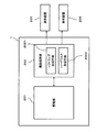
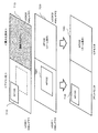
図1は、本発明の実施の形態にかかるマルチ画像表示システムの概略図である。
マルチ画像表示システム1は、管理部201、画像処理部202、表示装置203、204を有する。
Hereinafter, specific embodiments to which the present invention is applied will be described in detail with reference to the drawings.
FIG. 1 is a schematic diagram of a multi-image display system according to an embodiment of the present invention.
The multi-image display system 1 includes a
管理部201は、複数の表示レイヤに対して配置される画像の配置情報、重ね合わせ情報を管理する。ここで、表示レイヤは、表示装置203、204に対応するように領域を分割されている。管理部201は、画像の配置情報、重ね合わせ情報を基に描画処理部202に画像の再配置命令を送信する。
The
描画処理部202は、管理部201から受信した再配置命令に基づいて、表示レイヤに対して画像の生成又は配置変更等の再配置処理を実行する。また、該描画処理部202は、各画像に対応する描画バッファに格納された複数の画像を、ソフトウェア的に合成し、ある表示レイヤに割り当てられている単一のフレームバッファ上に出力するソフトウェア合成手段と、各画像に対応する描画バッファを複数の表示レイヤに割り当て、ハードウェアの機能(OSD)を利用して前記画像の重ね合わせを行うハードウェア合成手段とを有する。
The
該ソフトウェア合成手段もしくは該ハードウェア合成手段により複数の画像を合成し、表示装置203、204に表示することができる。
なお、本発明は複数の表示装置を有するマルチ画像表示システムに適用でき、表示装置の数は本実施の形態において例示した数に限られない。
A plurality of images can be synthesized by the software synthesizing unit or the hardware synthesizing unit and displayed on the
Note that the present invention can be applied to a multi-image display system having a plurality of display devices, and the number of display devices is not limited to the number exemplified in this embodiment.
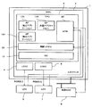
図2は、本発明の実施の形態にかかるマルチ画像表示システムの詳細を示す図である。本実施の形態では、複数のタッチパネル付き表示装置を接続可能な車載コンピュータを想定する。この車載コンピュータは、表示装置毎に異なる複数のGUI(Graphical User Interface)アプリケーションを独立させることが可能である。UNIX(登録商標)サーバーとX端末のシステムに似ているが、本実施の形態では単一の高性能マルチコアCPUのみで同様の機能を実現可能である。 FIG. 2 is a diagram showing details of the multi-image display system according to the embodiment of the present invention. In this embodiment, an in-vehicle computer capable of connecting a plurality of touch panel display devices is assumed. This in-vehicle computer can make a plurality of GUI (Graphical User Interface) applications different for each display device independent. Although it is similar to a UNIX (registered trademark) server and an X terminal system, in this embodiment, the same function can be realized only by a single high-performance multi-core CPU.
図2は、本発明の実施の形態にかかるマルチ画像表示システムの詳細を示す図である。マルチ画像表示システム1は、MPU2、LCD(Liquid Cristal Display)6、7、LCDC4、5及び外部RAM8を有する。MPU2は、CPU等からなる処理部3を有する。処理部3は、OS10がインストールされている。OS10は、APM(Application Manager)20、描画システム30、GUIアプリケーション100、101、102を有する。
APM20は、管理部として機能し、描画システム30とLCDC4、5は、描画処理部として機能する。
FIG. 2 is a diagram showing details of the multi-image display system according to the embodiment of the present invention. The multi-image display system 1 includes an MPU 2, LCDs (Liquid Crystal Display) 6 and 7,
The
LCDC4、5は、複数のHWレイヤを割り当て可能なLCDコントローラである。該HWレイヤは、表示レイヤとして機能する。LCDC6、7は、複数のHWレイヤに割り当てられたバッファの表示情報をハードウェアで合成(後述するハードウェア合成)して、RGB信号としてLCD6、7に出力する。LCD6、7は、表示装置として機能する。
なお、単一のLCDCで複数の表示装置に対応したものであってもよいが、本実施の形態では複数のLCDC6,7を有する形態について記載する。本実施の形態では、LCD6、7をそれぞれ車載コンピュータのフロントモニタとリアモニタとして使用することを想定する。
また、本発明は複数のLCDC及びLCDを有するマルチ画像表示システムに適用でき、LCDC、LCDの数は本実施の形態において例示した数に限られない。
Although a single LCDC may correspond to a plurality of display devices, in this embodiment, a mode having a plurality of LCDCs 6 and 7 will be described. In the present embodiment, it is assumed that the LCDs 6 and 7 are used as a front monitor and a rear monitor of an in-vehicle computer, respectively.
In addition, the present invention can be applied to a multi-image display system having a plurality of LCDCs and LCDs, and the number of LCDCs and LCDs is not limited to the number exemplified in the present embodiment.
OS10は、UNIX(登録商標)等のOS10であり、マルチメディアアプリケーション(カーナビゲーション、CD&DVDプレーヤー、デジタルテレビ放送、インターネットブラウザ、ゲーム等)をGUIアプリケーション100、101、102として有している。
The OS 10 is an OS 10 such as UNIX (registered trademark), and has multimedia applications (car navigation, CD & DVD player, digital TV broadcast, Internet browser, game, etc.) as
APM20は、特願2007−334854に記載されたAPMを単一OSでも使用可能にしたものであり、一つのAPMで複数のHWレイヤを管理可能となったものである。GUIアプリケーション100、101、102が配置するウィンドウの配置情報、重ね合わせ情報を管理する。APM20は、GUIアプリケーションの配置情報、重ね合わせ情報を基に描画システム30にGUIアプリケーションの再配置命令を送信する。
The
描画システム30は、透過ウィンドウをサポートしたXwindowsystem等のウィンドウシステムであり、透過ウィンドウを描画することが可能である。描画システム30は、APM20から受信した再配置命令に基づいてGUIアプリケーションのウィンドウ及び透過ウィンドウの再配置処理(ウィンドウの生成、配置変更等)を行う。ここで、透過ウィンドウとは、自身を透過し、下のHWレイヤに表示された画像を透過して表示するものをいう。
The
続いて、本実施の形態にかかるマルチ画像表示システムにおける画像合成処理について説明する。
本実施の形態におけるマルチ画像表示システムは、LCD6、7毎に独立して動作するGUIアプリケーションである独立アプリケーションと、各LCD6、7からのタッチイベント等の入力イベント及び画像出力機能が共有されるGUIアプリケーションである共有アプリケーションを有する。
Next, image composition processing in the multi-image display system according to the present embodiment will be described.
The multi-image display system according to the present embodiment includes an independent application that is a GUI application that operates independently for each of the LCDs 6 and 7, and a GUI that shares input events such as touch events from the LCDs 6 and 7 and an image output function. Have a shared application that is an application.
独立アプリケーションは、1つのLCDのみに表示可能なウィンドウである個別表示ウィンドウを有することができる。
共通アプリケーションは、個別表示ウィンドウと、全LCDで共有あるいは指定されえたLCD以外の全LCDで共有可能なウィンドウである共通表示ウィンドウの両方を有することができる。また、各ウィンドウは、それぞれ同じ座標に配置、重ね合わせをすることも可能である。
なお、個別表示ウィンドウは一部を透過させることも可能である。
本実施の形態における各ウィンドウは、ハードウエア合成(HW合成)又はソフトウェア合成(SW合成)のいずれかの手法によって合成され、LCD6、7に表示することができる。
The independent application can have an individual display window that is a window that can be displayed on only one LCD.
The common application can have both an individual display window and a common display window that is a window that can be shared by all LCDs other than the LCD that can be shared or designated by all LCDs. Each window can be arranged and overlapped at the same coordinates.
The individual display window can be partially transparent.
The windows in the present embodiment can be synthesized by either hardware synthesis (HW synthesis) or software synthesis (SW synthesis) and displayed on the LCDs 6 and 7.
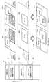
図3に本発明の実施の形態にかかる共通表示ウィンドウのHW合成を示す。
本実施の形態では、描画システム30が有する仮想表示空間を2つに分割し、それぞれをフロントモニタとリアモニタに割り当てている。
描画システム30及びHW合成される共通表示ウィンドウは、描画用のバッファとして外部RAM8内の領域を使用する。描画システム30によって生成された各ウィンドウの描画データは、描画システム30によって重ね合わせ処理が行われる前に、該バッファに格納される。
FIG. 3 shows HW composition of the common display window according to the embodiment of the present invention.
In the present embodiment, the virtual display space of the
The common display window combined with the
描画システム30の使用するフレームバッファ81及び共通表示ウィンドウ520が使用する描画バッファ83は、HWレイヤに割り当てられる。該バッファ81、83とHWレイヤの関連付けは、LCDC6、7のレジスタを制御することにより行われる。レジスタ設定パラメータとしては、該バッファ81、83の先頭アドレス、該バッファ81、83のサイズ(幅、高さ)、実際にLCD6、7への表示対象となる領域の情報(オフセット値、幅、高さ)、拡大率(HW合成時の全画面表示等に使用する)、HWレイヤ全体としての透過率(これとは別にビット単位で透過率を設定することも可能である)等がある。
本実施の形態では、最も表示優先度の高いHWレイヤに描画システム30用のフレームバッファ81が割り当てられており、2番目以降のHWレイヤのそれぞれには、共通表示ウィンドウ毎に設けられたHW合成される共通表示ウィンドウ用の描画バッファがそれぞれ割り当てられる。なお、本実施の形態では、2番目のHWレイヤに、共通表示ウィンドウ520の描画バッファ83が割り当てられている。
The
In the present embodiment, the
図3のウィンドウ510、511は独立アプリケーションの個別表示ウィンドウである。共通表示ウィンドウ520の描画データは、HWレイヤ2に割り当てられた描画バッファ83に格納されている。また、共通アプリケーションは、一部を透過させた個別表示ウィンドウ513を有することができる。これにより、例えば操作ボタンのみで他の部分は透けている個別表示ウィンドウ513を有することができる。該個別表示ウィンドウ513の描画データは、共通表示ウィンドウ520と同様に描画バッファ82に格納される。描画バッファ82に格納された該個別表示ウィンドウ513の描画データは、フレームバッファ81にコピーされ、HWレイヤ1に該個別表示ウィンドウ513が生成される。
また、APM20は、HWレイヤ2に描画されるウィンドウ520を配置情報に基づいて、このウィンドウを表示させるための透過ウィンドウをHWレイヤ1に生成させる再配置命令を描画システム30に通知する。この通知を受けた描画システム30は、HWレイヤ1に透過ウィンドウ512を生成する。
Further, the
LCDC4、5は、これらのウィンドウが生成されたHWレイヤ1、2を画面合成することにより、ウィンドウを重ね合わせた画面を生成し、LCD6、7に表示する。
カーナビナビゲーションアプリケーションのように、走行規制のため、走行中は運転席側のフロントモニタのメニュー等の一部の操作を伴う表示を非表示としたい場合は、上述のように一部が透過した個別表示ウィンドウと透過ウィンドウを使用して、ウィンドウの合成を行うことで実現が可能である。
The
If you want to hide the display with some operations, such as the front monitor menu on the driver's seat side, because of travel restrictions, such as in car navigation applications, the individual partly transparent as described above This can be realized by combining windows using a display window and a transparent window.
図4に本発明の実施の形態にかかる共通表示ウィンドウのSW合成を示す。
図4のウィンドウ610、611は独立アプリケーションの個別表示ウィンドウである。共通アプリケーションの共通表示ウィンドウ620及び個別表示ウィンドウ613の描画データは、前述と同様に描画バッファ82、83に格納される。各描画データは、フレームバッファ81にコピーされ、描画システム30であるXwindowsystem等が有する機能を用いることで、ウィンドウを重ね合わせ合わせた画面の生成を実現する。
FIG. 4 shows the SW composition of the common display window according to the embodiment of the present invention.
The
本実施の形態にかかるマルチ画像表示システムは、上述したいずれかの合成手段でウィンドウを合成することで、LCD6、7毎に独立して動作する独立アプリケーションと、各LCD6、7への画像出力が共有される共有アプリケーションを混在させて、同時に実行表示することが可能となる。 In the multi-image display system according to the present embodiment, by combining the windows with any of the combining means described above, an independent application that operates independently for each of the LCDs 6 and 7 and an image output to each of the LCDs 6 and 7 can be performed. It is possible to simultaneously display shared applications that are shared.
また、HW合成においては、透過ウィンドウ又は一部が透過した個別表示ウィンドウを分割された仮想表示空間毎に異なる座標位置に配置させることにより、共通表示ウィンドウをLCD毎に異なる座標位置に表示することも可能である。SW合成においても、共通表示ウィンドウ及び一部が透過した個別表示ウィンドウを分割された仮想表示空間毎に異なる座標位置に配置することにより、共通表示ウィンドウをLCD毎に異なる座標位置に表示することが可能である In HW composition, a common display window is displayed at a different coordinate position for each LCD by arranging a transparent window or an individual display window partially transparent at different coordinate positions for each divided virtual display space. Is also possible. In the SW composition, the common display window and the individual display window partially transparent can be arranged at different coordinate positions for each divided virtual display space, so that the common display window can be displayed at different coordinate positions for each LCD. Is possible
ここで、本実施の形態においては、独立アプリケーションの個別表示ウィンドウは、描画データを直接フレームバッファ81に格納して表示してもよく、共通アプリケーションの個別表示ウィンドウと同様に一度描画バッファに格納し、その後フレームバッファ81にコピーして表示してもよい。また、独立アプリケーションの個別表示ウィンドウを描画バッファに格納し、表示優先度が2番目以降のHWレイヤに割り当てて、HW合成して表示する実施の形態としてもよい。
Here, in the present embodiment, the individual display window of the independent application may display the drawing data directly stored in the
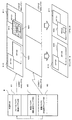
図5に本発明の実施の形態にかかる共通表示ウィンドウの最大化表示及びアイコン化を示す。共通表示ウィンドウ720をアイコン化したい場合は、透過ウィンドウ又は一部が透過した個別表示ウィンドウを一時的に消去することにより、実現可能である。また、共通表示ウィンドウ720を最大化表示したい場合は、LCDCの有するOSD機能を利用することで、高速にズーム表示させることが可能である。共通表示ウィンドウの最大化表示時のズームの有無は、アプリケーション毎に設定が可能である。
FIG. 5 shows the maximized display and iconization of the common display window according to the embodiment of the present invention. When the
車載コンピュータには、CD&DVDドライブ及びデジタルテレビ放送チューナーが内蔵されているが、どちらも一系統のみ有している場合は、CD&DVDプレーヤーアプリケーション及びデジタルテレビ放送アプリケーションは、共通アプリケーションとして、全てのLCDに入出力を共有される。この場合に、走行規制のため、走行中は運転席側のフロントモニタのみアイコン化をしたいときは、上述の方法により実現が可能である。 The in-vehicle computer has a built-in CD & DVD drive and digital TV broadcast tuner, but if both have only one system, the CD & DVD player application and the digital TV broadcast application are input to all LCDs as a common application. The output is shared. In this case, if it is desired to iconify only the front monitor on the driver's seat side during traveling because of travel restrictions, this can be realized by the above-described method.
続いて、共通表示ウィンドウの合成優先度、及びSW合成とHW合成の切替処理について説明する。
共通表示ウィンドウ毎に、16段階(0〜15)の合成優先度が割り当てられている。合成優先度の設定は、アプリケーションからの専用のAPIの呼び出し、又はAPMが管理するデータベースやスクリプト等を使用して行う。データベースやスクリプトを使用した場合、各アプリケーションが意識せずに合成優先度の設定を行うことが可能となる。
Next, the combination priority of the common display window and the switching process between the SW combination and the HW combination will be described.
Sixteen levels (0 to 15) of synthesis priority are assigned to each common display window. The synthesis priority is set by calling a dedicated API from an application or using a database or script managed by APM. When a database or script is used, it is possible to set the synthesis priority without each application being aware of it.
合成優先度0(デフォールト値)の場合は、SW合成に割り当てられる。既存の汎用アプリケーションを共有化したい場合や、例えばボタン表示のみで他の領域は透過であるもの等の処理負荷の軽い共通表示ウィンドウを対象としている。
合成優先度15の場合は、HW合成に割り当てられる。描画処理の負荷が非常に重い共通表示ウィンドウや外部の専用プロセッサー(テレビやDVDのバックエンドチップ等)からの描画が必要とされる場合を対象としている。
When the synthesis priority is 0 (default value), it is assigned to SW synthesis. When an existing general-purpose application is desired to be shared, for example, a common display window with a light processing load such as a button display only and other areas are transparent is targeted.
In the case of the synthesis priority 15, it is assigned to HW synthesis. This is intended for cases where drawing is required from a common display window or an external dedicated processor (such as a TV or DVD back-end chip) that has a very heavy drawing processing load.
合成優先度が1から14の場合は、HW合成優先である。HWレイヤに空きがある場合は、HW合成され、HWレイヤに空きが無い場合は、SW合成される。
合成優先度の低い共通表示ウィンドウが、HW合成に割り当てられており、より合成優先度の高い共通表示ウィンドウが新規に作成され、HWレイヤに空きが無い場合は、APMは、HW合成されている合成優先度の低い共通表示ウィンドウを、自動的にSW合成に切り替える。
When the synthesis priority is 1 to 14, HW synthesis priority is given. When there is a vacancy in the HW layer, HW synthesis is performed, and when there is no vacancy in the HW layer, SW synthesis is performed.
A common display window with a low synthesis priority is assigned to HW synthesis. If a common display window with a higher synthesis priority is newly created and there is no free space in the HW layer, the APM is HW synthesized. The common display window with a low composition priority is automatically switched to SW composition.
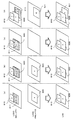
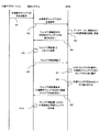
図6に合成優先度の高い共有アプリケーションの共通表示ウィンドウを新規作成する場合の共通表示ウィンドウの切替処理の状態遷移図を示す。図7に、この場合のシーケンス図を示す。
図6(a)は、独立アプリケーションの個別表示ウィンドウ810と、透過ウィンドウ811を用いてHW合成された共通アプリケーションの共通表示ウィンドウ820をLCDに表示されている状態を示している。
FIG. 6 shows a state transition diagram of the switching process of the common display window when a new common display window of the shared application having a high composition priority is created. FIG. 7 shows a sequence diagram in this case.
FIG. 6A shows a state in which the
この状態から、新たな共通アプリケーションが起動されると、該共通アプリケーションから描画システム30に共通表示ウィンドウの生成要求が通知される(ステップS1)。これを受けた描画システム30は、APM20に共通表示ウィンドウの生成要求が通知される(ステップS2)。この通知により、該共通表示ウィンドウの配置情報及び描画バッファのアドレス情報(先頭アドレス、サイズ等)が、APM20に通知される。
When a new common application is activated from this state, a request for generating a common display window is notified from the common application to the drawing system 30 (step S1). Upon receiving this, the
ここで、新たに生成される共通表示ウィンドウの合成優先度が、既に表示されている共通表示ウィンドウ820より高く、HWレイヤに空きが無い場合は、共通表示ウィンドウ820のSW合成による表示への切替処理を行うことで、HWレイヤの空きをつくる。そのため、APM20は、データベースに格納されている各ウィンドウの配置情報を参照、更新し、共通表示ウィンドウ820の表示を含むウィンドウ再配置命令を描画システム30に通知する(ステップS3、S4)。
If the compositing priority of the newly generated common display window is higher than that of the already displayed
図6(b)は、該再配置命令を受けた描画システム30が、ウィンドウの再配置処理を行った状態である(ステップS5)。ここでは、共通表示ウィンドウ820がSW合成とHW合成の両方の合成された表示を同時にLCDに表示している。このように該切替処理時に、一時的に両方の合成表示を表示することにより、共通表示ウィンドウ820のちらつきを抑えることが可能である。
描画システム30からウィンドウ再配置終了の通知を受けたAPM20は、共通表示ウィンドウ820をHWレイヤ2から切り離す(ステップS6、S7)。その時の状態を図6(c)に示す。
FIG. 6B shows a state in which the
Receiving the notice of window rearrangement completion from the
次にAPM20は、HWレイヤ2を新たに表示される共通表示ウィンドウ821に割り当て、透過ウィンドウ813の作成を含むウィンドウ再配置命令を描画システム20に通知する(ステップS8、S9)。該通知を受けた描画システム20により透過ウィンドウ813が生成され、HW合成により共通表示ウィンドウ821がLCDに表示される(S10)。その時の状態を図6(d)に示す。
このように、APM30が自動的に透過ウィンドウの生成を依頼することにより、新たに起動した共通アプリケーション側で該切替処理を意識する必要がなくなる。
Next, the
As described above, the
また、上記切替処理により、HW合成に割り当てられる合成優先度を有する共通アプリケーションをHWレイヤ数以上実行し、同時に表示することが可能となる。
その他、上述のように、描画処理の負荷が重い共通アプリケーションは、HW合成を行うように合成優先度を設定することで、高速なウィンドウ合成処理が可能となる。例えば、カーナビゲーションアプリケーションにおける地図画面でGPU(Graphic Processer Unit)を占有し、描画システム30でGPUを使用できない場合や、デジタル放送アプリケーションやDVDアプリケーション等のように数10ms単位で描画が発生するアプリケーションを共有する場合にHW合成が有効である。既存アプリケーション資産に関しては、SW合成でアプリケーションの共有を行うことが可能である。
Further, by the switching process, it is possible to execute the common applications having the combination priority assigned to the HW combination more than the number of HW layers and display them simultaneously.
In addition, as described above, a common application having a heavy drawing processing load can perform high-speed window composition processing by setting the composition priority so as to perform HW composition. For example, when a GPU (Graphic Processor Unit) is occupied on a map screen in a car navigation application and the GPU cannot be used in the
ここで、本実施の形態では、共通表示ウィンドウの切替処理について説明したが、個別表示ウィンドウに適用した実施の形態としてもよい。 Here, in the present embodiment, the switching process of the common display window has been described, but the embodiment may be applied to an individual display window.
1 マルチ画像表示システム
2 MPU
3 処理部
4、5 LCDC
6、7 LCD
8 外部RAM
10 OS
20 APM
30 描画システム
81 フレームバッファ
82、83 描画バッファ
100、101 独立アプリケーション
102 共通アプリケーション
201 管理部
202 描画処理部
203、204 表示装置
510、511、512、513、520、610、611、613、620、710、713、720、810、811、813、820、821 ウィンドウ
2021 ソフトウェア合成手段
2022 ハードウェア合成手段
1 Multi-image display system 2 MPU
3
6, 7 LCD
8 External RAM
10 OS
20 APM
30
Claims (10)
独立アプリケーション及び共通アプリケーションを実行するCPUと、
前記独立アプリケーションから生成される個別表示画像と、前記共通アプリケーションから生成される共通表示画像の管理を行う管理部と、
前記管理部からの命令に応じて、前記個別表示画像を生成して前記第1の描画バッファにおける前記第1の領域及び前記第2の領域のいずれか1つに配置するとともに、前記共通表示画像を生成して前記第2の描画バッファにおける前記第1の領域及び前記第2の領域の両方に配置する配置処理を実行する描画処理部とを備え、
当該描画処理部は、
前記第1の描画バッファ及び前記第2の描画バッファに格納された前記個別表示画像及び前記共通表示画像を、ソフトウェア的に合成し、前記フレームバッファ上に出力するソフトウェア合成手段と、
前記フレームバッファ及び前記第2の描画バッファのそれぞれを第1の表示レイヤ及び第2の表示レイヤに割り当てるとともに、前記第1の描画バッファの個別表示画像を前記フレームバッファにコピーし、ハードウェアの機能を利用して前記第1の表示レイヤ及び前記第2の表示レイヤを合成することにより、前記フレームバッファの個別表示画像及び前記第2の描画バッファの共通表示画像の合成を行うハードウェア合成手段とを有し、
前記ソフトウェア合成手段によって前記フレームバッファ上に合成された画像、又は、前記ハードウェア合成手段によって合成された画像における、前記第1の領域及び前記第2の領域のそれぞれを前記第1の表示装置及び前記第2の表示装置に表示するマルチ画像表示システム。 A frame buffer including a first region and a second region corresponding to each of the first display device and the second display device; a first drawing buffer including the first region and the second region; And a storage unit having a second drawing buffer including the first region and the second region;
A CPU that executes an independent application and a common application;
A management unit that manages an individual display image generated from the independent application and a common display image generated from the common application ;
In response to a command from the management unit, the individual display image is generated and arranged in any one of the first region and the second region in the first drawing buffer, and the common display image A drawing processing unit that executes an arrangement process for generating and arranging in both the first area and the second area in the second drawing buffer ;
The drawing processing unit
And software combining means a first drawing buffer and the second of said individual display image and the common display image stored in the rendering buffer, software synthesized, and outputs on the frame buffer,
Said frame buffer and said second assign each drawing buffer to the first display layer and a second display layer Rutotomoni, copy the individual display image of the first drawing buffer to the frame buffer, the hardware Hardware combining means for combining the individual display image of the frame buffer and the common display image of the second drawing buffer by combining the first display layer and the second display layer using a function. It has a door,
Each of the first area and the second area in the image synthesized on the frame buffer by the software synthesizing unit or the image synthesized by the hardware synthesizing unit is displayed on the first display device and A multi-image display system for displaying on the second display device .
前記共通表示画像を表示装置毎に異なる座標位置に表示する請求項1に記載のマルチ画像表示システム。 Software synthesis means or hardware synthesis means
The multi-image display system according to claim 1, wherein the common display image is displayed at a different coordinate position for each display device.
前記共通表示画像に対して設定された合成優先度に基づいて、前記共通表示画像を前記ソフトウェア合成手段もしくは前記ハードウェア合成手段のいずれにより合成するかを決定する請求項1又は2に記載のマルチ画像表示システム。 The management unit
3. The multi-unit according to claim 1, wherein whether the common display image is to be combined by the software combining unit or the hardware combining unit is determined based on a combination priority set for the common display image. Image display system.
前記独立アプリケーション及び前記共通アプリケーションのそれぞれに割り当てられたウィンドウとして表示される画像である請求項1乃至3のいずれか1項に記載のマルチ画像表示システム。 Each of the individual display image and the common display image is
Multi-image display system according to any one of claims 1 to 3 is an image displayed as a window assigned to each of said independent application and the common application.
前記共通表示画像の合成を前記ソフトウェア合成手段による合成に切り替える時に、前記ソフトウェア合成手段による画像の表示と前記ハードウェア合成手段による画像の表示とを一時的に同時に表示する請求項5に記載のマルチ画像表示システム。 The switching processing means includes
The multi display according to claim 5 , wherein when the synthesis of the common display image is switched to the synthesis by the software synthesis unit, the image display by the software synthesis unit and the image display by the hardware synthesis unit are temporarily displayed simultaneously. Image display system.
CPUによって、独立アプリケーション及び共通アプリケーションの実行を開始する第1のステップと、
前記共通アプリケーションから生成される共通表示画像を、ソフトウェア合成処理とハードウェア合成処理のいずれにより合成処理を実行するかを決定する第2のステップと、
前記独立アプリケーションから個別表示画像を生成して前記第1の描画バッファにおける前記第1の領域及び前記第2の領域のいずれか1つに配置するとともに、前記共通アプリケーションから共通表示画像を生成して前記第2の描画バッファにおける前記第1の領域及び前記第2の領域の両方に配置する第3のステップと、
前記ソフトウェア合成処理を実行することを決定した場合に、前記第1の描画バッファ及び前記第2の描画バッファに格納された前記個別表示画像及び前記共通表示画像を、ソフトウェア的に合成し、前記フレームバッファ上に出力する第4のステップと、
前記ハードウェア合成処理を実行することを決定した場合に、前記フレームバッファ及び前記第2の描画バッファのそれぞれを第1の表示レイヤ及び第2の表示レイヤに割り当てるとともに、前記第1の描画バッファの個別表示画像を前記フレームバッファにコピーし、ハードウェアの機能を利用して前記第1の表示レイヤ及び前記第2の表示レイヤを合成することにより、前記フレームバッファの個別表示画像及び前記第2の描画バッファの共通表示画像の合成を行う第5のステップと、
前記ソフトウェア合成処理によって前記フレームバッファ上に合成された画像、又は、前記ハードウェア合成処理によって合成された画像における、前記第1の領域及び前記第2の領域のそれぞれを前記第1の表示装置及び前記第2の表示装置に表示する第6のステップと、を備えた画像処理方法。 A frame buffer including a first region and a second region corresponding to each of the first display device and the second display device; a first drawing buffer including the first region and the second region; And an image processing method for displaying an image on the first display device and the second display device using a second drawing buffer including the first region and the second region ,
A first step of starting execution of the independent application and the common application by the CPU;
A second step of determining whether to perform the synthesis process on the common display image generated from the common application by software synthesis process or hardware synthesis process;
An individual display image is generated from the independent application and arranged in one of the first area and the second area in the first drawing buffer, and a common display image is generated from the common application. A third step of arranging in both the first region and the second region in the second drawing buffer;
Wherein when it is decided to execute the software synthesis process, the first drawing buffer and the second of said individual display image and the common display image stored in the rendering buffer, software synthesized, the frame A fourth step of outputting on the buffer;
Wherein when it is decided to perform hardware synthesis process, assign each of the frame buffer and the second drawing buffer to the first display layer and a second display layer Rutotomoni, the first drawing buffer The individual display image of the frame buffer is copied to the frame buffer, and the first display layer and the second display layer are synthesized using a hardware function, so that the individual display image of the frame buffer and the second display layer are combined. A fifth step of synthesizing the common display image of the drawing buffer ;
Each of the first area and the second area in the image synthesized on the frame buffer by the software synthesis process or the image synthesized by the hardware synthesis process is displayed on the first display device and A sixth step of displaying on the second display device .
CPUによって、独立アプリケーション及び共通アプリケーションの実行を開始する第1のステップと、
前記共通アプリケーションから生成される共通表示画像を、ソフトウェア合成処理とハードウェア合成処理のいずれにより合成処理を実行するかを決定する第2のステップと、
前記独立アプリケーションから個別表示画像を生成して前記第1の描画バッファにおける前記第1の領域及び前記第2の領域のいずれか1つに配置するとともに、前記共通アプリケーションから共通表示画像を生成して前記第2の描画バッファにおける前記第1の領域及び前記第2の領域の両方に配置する第3のステップと、
前記ソフトウェア合成処理を実行することを決定した場合に、前記第1の描画バッファ及び前記第2の描画バッファに格納された前記個別表示画像及び前記共通表示画像を、ソフトウェア的に合成し、前記フレームバッファ上に出力する第4のステップと、
前記ハードウェア合成処理を実行することを決定した場合に、前記フレームバッファ及び前記第2の描画バッファのそれぞれを第1の表示レイヤ及び第2の表示レイヤに割り当てるとともに、前記第1の描画バッファの個別表示画像を前記フレームバッファにコピーし、ハードウェアの機能を利用して前記第1の表示レイヤ及び前記第2の表示レイヤを合成することにより、前記フレームバッファの個別表示画像及び前記第2の描画バッファの共通表示画像の合成を行う第5のステップと、
前記ソフトウェア合成処理によって前記フレームバッファ上に合成された画像、又は、前記ハードウェア合成処理によって合成された画像における、前記第1の領域及び前記第2の領域のそれぞれを前記第1の表示装置及び前記第2の表示装置に表示する第6のステップと、をコンピュータに対して実行させる画像処理プログラム。 A frame buffer including a first region and a second region corresponding to each of the first display device and the second display device; a first drawing buffer including the first region and the second region; And an image processing program for displaying an image on the first display device and the second display device using a second drawing buffer including the first region and the second region ,
A first step of starting execution of the independent application and the common application by the CPU;
A second step of determining whether to perform the synthesis process on the common display image generated from the common application by software synthesis process or hardware synthesis process;
An individual display image is generated from the independent application and arranged in one of the first area and the second area in the first drawing buffer, and a common display image is generated from the common application. A third step of arranging in both the first region and the second region in the second drawing buffer;
Wherein when it is decided to execute the software synthesis process, the first drawing buffer and the second of said individual display image and the common display image stored in the rendering buffer, software synthesized, the frame A fourth step of outputting on the buffer;
Wherein when it is decided to perform hardware synthesis process, assign each of the frame buffer and the second drawing buffer to the first display layer and a second display layer Rutotomoni, the first drawing buffer The individual display image of the frame buffer is copied to the frame buffer, and the first display layer and the second display layer are synthesized using a hardware function, so that the individual display image of the frame buffer and the second display layer are combined. A fifth step of synthesizing the common display image of the drawing buffer ;
Each of the first area and the second area in the image synthesized on the frame buffer by the software synthesis process or the image synthesized by the hardware synthesis process is displayed on the first display device and An image processing program for causing a computer to execute a sixth step of displaying on the second display device .
Priority Applications (1)
| Application Number | Priority Date | Filing Date | Title |
|---|---|---|---|
| JP2008223551A JP5229727B2 (en) | 2008-09-01 | 2008-09-01 | Multi-image display system, image processing method and program |
Applications Claiming Priority (1)
| Application Number | Priority Date | Filing Date | Title |
|---|---|---|---|
| JP2008223551A JP5229727B2 (en) | 2008-09-01 | 2008-09-01 | Multi-image display system, image processing method and program |
Publications (2)
| Publication Number | Publication Date |
|---|---|
| JP2010060623A JP2010060623A (en) | 2010-03-18 |
| JP5229727B2 true JP5229727B2 (en) | 2013-07-03 |
Family
ID=42187522
Family Applications (1)
| Application Number | Title | Priority Date | Filing Date |
|---|---|---|---|
| JP2008223551A Expired - Fee Related JP5229727B2 (en) | 2008-09-01 | 2008-09-01 | Multi-image display system, image processing method and program |
Country Status (1)
| Country | Link |
|---|---|
| JP (1) | JP5229727B2 (en) |
Families Citing this family (3)
| Publication number | Priority date | Publication date | Assignee | Title |
|---|---|---|---|---|
| CN103064645A (en) * | 2011-10-21 | 2013-04-24 | 联想(北京)有限公司 | Display method and electronic equipment |
| CN106469039B (en) * | 2016-09-28 | 2019-05-03 | 华为技术有限公司 | Image display method and system |
| JP2020177073A (en) * | 2019-04-16 | 2020-10-29 | 株式会社デンソー | Vehicle equipment, control method of vehicle equipment |
Family Cites Families (2)
| Publication number | Priority date | Publication date | Assignee | Title |
|---|---|---|---|---|
| JP2006227555A (en) * | 2005-02-18 | 2006-08-31 | Okayama Prefecture | Multi-window display device and multi-window image management method |
| JP5305564B2 (en) * | 2006-03-30 | 2013-10-02 | クラリオン株式会社 | Navigation system and output control method |
-
2008
- 2008-09-01 JP JP2008223551A patent/JP5229727B2/en not_active Expired - Fee Related
Also Published As
| Publication number | Publication date |
|---|---|
| JP2010060623A (en) | 2010-03-18 |
Similar Documents
| Publication | Publication Date | Title |
|---|---|---|
| EP2962191B1 (en) | System and method for virtual displays | |
| US10031712B2 (en) | System and method for display mirroring | |
| CN102681887B (en) | System and method used for controlling virtual screen | |
| CN104123110A (en) | Android double-screen extraordinary image display method | |
| JP6364949B2 (en) | Information processing apparatus and information processing method | |
| CN102685589A (en) | Method and device for switchover displaying of video window and message window | |
| JP5045428B2 (en) | Image display system, image display method, and program | |
| CN103503430B (en) | Play control system and method | |
| JP4780101B2 (en) | Image display system, image display method, and program | |
| JP5229727B2 (en) | Multi-image display system, image processing method and program | |
| US9298413B1 (en) | System, method, and computer program product for changing a state of operation of a display system with respect to at least a portion of an image occluded by a non-display surface | |
| US20140026100A1 (en) | Method and apparatus for displaying an image, and computer readable recording medium | |
| WO2024044936A1 (en) | Composition for layer roi processing | |
| CN112770169B (en) | List circulating page turning method and display device | |
| US20220358899A1 (en) | Control method for magnifying display screen and associated display system | |
| CN116700850A (en) | Display method and electronic device | |
| US7844900B2 (en) | Visual management system | |
| CN110753194A (en) | Dual-screen different display method, storage medium and electronic equipment | |
| JP7709256B2 (en) | Information processing device, display control method and program | |
| US9582158B2 (en) | Efficient usage of screen real estate on an electronic device | |
| CN116233512A (en) | Display equipment and data display method | |
| WO2025138015A1 (en) | Driving system, method, and device for display screen, display system, and vehicle | |
| CN119065771A (en) | A multi-buffer graphics display method, system, medium, program product and device | |
| WO2025214054A1 (en) | Interface generation apparatus and interface generation method | |
| CN118061778A (en) | Display method of intelligent cockpit display system and intelligent cockpit display system |
Legal Events
| Date | Code | Title | Description |
|---|---|---|---|
| A977 | Report on retrieval |
Free format text: JAPANESE INTERMEDIATE CODE: A971007 Effective date: 20120606 |
|
| A131 | Notification of reasons for refusal |
Free format text: JAPANESE INTERMEDIATE CODE: A131 Effective date: 20121204 |
|
| A521 | Request for written amendment filed |
Free format text: JAPANESE INTERMEDIATE CODE: A523 Effective date: 20130121 |
|
| TRDD | Decision of grant or rejection written | ||
| A01 | Written decision to grant a patent or to grant a registration (utility model) |
Free format text: JAPANESE INTERMEDIATE CODE: A01 Effective date: 20130219 |
|
| A61 | First payment of annual fees (during grant procedure) |
Free format text: JAPANESE INTERMEDIATE CODE: A61 Effective date: 20130312 |
|
| FPAY | Renewal fee payment (event date is renewal date of database) |
Free format text: PAYMENT UNTIL: 20160329 Year of fee payment: 3 |
|
| R150 | Certificate of patent or registration of utility model |
Ref document number: 5229727 Country of ref document: JP Free format text: JAPANESE INTERMEDIATE CODE: R150 Free format text: JAPANESE INTERMEDIATE CODE: R150 |
|
| S533 | Written request for registration of change of name |
Free format text: JAPANESE INTERMEDIATE CODE: R313533 |
|
| R350 | Written notification of registration of transfer |
Free format text: JAPANESE INTERMEDIATE CODE: R350 |
|
| LAPS | Cancellation because of no payment of annual fees |