JP5227420B2 - Filter device - Google Patents
Filter device Download PDFInfo
- Publication number
- JP5227420B2 JP5227420B2 JP2010538548A JP2010538548A JP5227420B2 JP 5227420 B2 JP5227420 B2 JP 5227420B2 JP 2010538548 A JP2010538548 A JP 2010538548A JP 2010538548 A JP2010538548 A JP 2010538548A JP 5227420 B2 JP5227420 B2 JP 5227420B2
- Authority
- JP
- Japan
- Prior art keywords
- plug
- filter
- filter element
- receptacle
- combustion engine
- Prior art date
- Legal status (The legal status is an assumption and is not a legal conclusion. Google has not performed a legal analysis and makes no representation as to the accuracy of the status listed.)
- Expired - Fee Related
Links
- 238000001914 filtration Methods 0.000 claims description 18
- 238000002485 combustion reaction Methods 0.000 claims description 16
- 239000007788 liquid Substances 0.000 claims description 13
- 238000011045 prefiltration Methods 0.000 claims description 7
- 238000004891 communication Methods 0.000 claims description 2
- 238000003780 insertion Methods 0.000 description 3
- 230000037431 insertion Effects 0.000 description 3
- 230000001419 dependent effect Effects 0.000 description 2
- 230000000694 effects Effects 0.000 description 2
- 239000010687 lubricating oil Substances 0.000 description 2
- 239000000463 material Substances 0.000 description 2
- 235000014676 Phragmites communis Nutrition 0.000 description 1
- 238000013459 approach Methods 0.000 description 1
- 238000004140 cleaning Methods 0.000 description 1
- 239000000356 contaminant Substances 0.000 description 1
- 230000003247 decreasing effect Effects 0.000 description 1
- 238000013461 design Methods 0.000 description 1
- 239000012530 fluid Substances 0.000 description 1
- 239000000446 fuel Substances 0.000 description 1
- 238000004519 manufacturing process Methods 0.000 description 1
- 239000002184 metal Substances 0.000 description 1
- 238000000034 method Methods 0.000 description 1
- 239000003921 oil Substances 0.000 description 1
- 238000007789 sealing Methods 0.000 description 1
- 238000003466 welding Methods 0.000 description 1
Images


Classifications
-
- B—PERFORMING OPERATIONS; TRANSPORTING
- B01—PHYSICAL OR CHEMICAL PROCESSES OR APPARATUS IN GENERAL
- B01D—SEPARATION
- B01D35/00—Filtering devices having features not specifically covered by groups B01D24/00 - B01D33/00, or for applications not specifically covered by groups B01D24/00 - B01D33/00; Auxiliary devices for filtration; Filter housing constructions
- B01D35/14—Safety devices specially adapted for filtration; Devices for indicating clogging
- B01D35/153—Anti-leakage or anti-return valves
-
- B—PERFORMING OPERATIONS; TRANSPORTING
- B01—PHYSICAL OR CHEMICAL PROCESSES OR APPARATUS IN GENERAL
- B01D—SEPARATION
- B01D35/00—Filtering devices having features not specifically covered by groups B01D24/00 - B01D33/00, or for applications not specifically covered by groups B01D24/00 - B01D33/00; Auxiliary devices for filtration; Filter housing constructions
- B01D35/005—Filters specially adapted for use in internal-combustion engine lubrication or fuel systems
-
- B—PERFORMING OPERATIONS; TRANSPORTING
- B01—PHYSICAL OR CHEMICAL PROCESSES OR APPARATUS IN GENERAL
- B01D—SEPARATION
- B01D35/00—Filtering devices having features not specifically covered by groups B01D24/00 - B01D33/00, or for applications not specifically covered by groups B01D24/00 - B01D33/00; Auxiliary devices for filtration; Filter housing constructions
- B01D35/16—Cleaning-out devices, e.g. for removing the cake from the filter casing or for evacuating the last remnants of liquid
-
- F—MECHANICAL ENGINEERING; LIGHTING; HEATING; WEAPONS; BLASTING
- F02—COMBUSTION ENGINES; HOT-GAS OR COMBUSTION-PRODUCT ENGINE PLANTS
- F02M—SUPPLYING COMBUSTION ENGINES IN GENERAL WITH COMBUSTIBLE MIXTURES OR CONSTITUENTS THEREOF
- F02M37/00—Apparatus or systems for feeding liquid fuel from storage containers to carburettors or fuel-injection apparatus; Arrangements for purifying liquid fuel specially adapted for, or arranged on, internal-combustion engines
- F02M37/22—Arrangements for purifying liquid fuel specially adapted for, or arranged on, internal-combustion engines, e.g. arrangements in the feeding system
- F02M37/32—Arrangements for purifying liquid fuel specially adapted for, or arranged on, internal-combustion engines, e.g. arrangements in the feeding system characterised by filters or filter arrangements
- F02M37/34—Arrangements for purifying liquid fuel specially adapted for, or arranged on, internal-combustion engines, e.g. arrangements in the feeding system characterised by filters or filter arrangements by the filter structure, e.g. honeycomb, mesh or fibrous
-
- B—PERFORMING OPERATIONS; TRANSPORTING
- B01—PHYSICAL OR CHEMICAL PROCESSES OR APPARATUS IN GENERAL
- B01D—SEPARATION
- B01D2201/00—Details relating to filtering apparatus
- B01D2201/40—Special measures for connecting different parts of the filter
- B01D2201/4007—Use of cam or ramp systems
-
- B—PERFORMING OPERATIONS; TRANSPORTING
- B01—PHYSICAL OR CHEMICAL PROCESSES OR APPARATUS IN GENERAL
- B01D—SEPARATION
- B01D2201/00—Details relating to filtering apparatus
- B01D2201/40—Special measures for connecting different parts of the filter
- B01D2201/4046—Means for avoiding false mounting of different parts
-
- B—PERFORMING OPERATIONS; TRANSPORTING
- B01—PHYSICAL OR CHEMICAL PROCESSES OR APPARATUS IN GENERAL
- B01D—SEPARATION
- B01D2201/00—Details relating to filtering apparatus
- B01D2201/52—Filter identification means
Landscapes
- Chemical & Material Sciences (AREA)
- Chemical Kinetics & Catalysis (AREA)
- Engineering & Computer Science (AREA)
- Combustion & Propulsion (AREA)
- Mechanical Engineering (AREA)
- General Engineering & Computer Science (AREA)
- Filtration Of Liquid (AREA)
- Lubrication Details And Ventilation Of Internal Combustion Engines (AREA)
Description
本発明は、請求項1の前文の機能を有する、特に自動車の内燃機関の液体を濾過するためのフィルタ装置に関する。 The invention relates to a filter device having the function of the preamble of claim 1, in particular for filtering the liquid of an internal combustion engine of a motor vehicle.
この種のフィルタ装置として、特許文献1に示される、特に自動車の内燃機関のための好ましくは潤滑油を浄化するオイルフィルタが知られている。公知のフィルタ装置は、フィルタエレメントを収容するためのフィルタハウジングを備え、そのフィルタハウジングは、濾過前側に入口を有し、濾過後側に出口を有する。挿入状態において、フィルタエレメントは、出口と連通する濾過前室から入口と連通する濾過後室を切り離す。さらにまた、周知のフィルタ装置のフィルタハウジングは、濾過後室と連通し、フィルタハウジングに形成される、軸方向に且つ偏心して突出するプラグのためのプラグレセプタクルを形成するドレーンラインを有する。そして、フィルタエレメントの挿入状態でプラグがレセプタクルに接続される。このように、フィルタエレメントがフィルタハウジングに適切に挿入されるときに、プラグはドレンラインを閉める。周知のフィルタ装置においては、簡略化されたプラグレセプタクルの発見及びプラグレセプタクルへのプラグの挿入のために、同心に配置されて螺旋状に上昇又は下降する傾斜路がハウジングに設けられている。そして、このようにドレーンラインの入口領域である、プラグレセプタクルは、傾斜路上端と傾斜路下端との間に配置される。そして、フィルタエレメントが挿入され又はねじ込まれるのに合わせ、カバーにねじ込まれるときに、フィルタエレメントの回転を通じ、また傾斜路に沿うプラグのスライドを通じ、プラグは自動的にプラグレセプタクルを見つけ、そこに貫入されてドレンラインを閉めることができる。周知のフィルタ装置の特に有利な実施形態においては、傾斜路に適合するプラグが設けられるフィルタエレメントだけが、プラグがカバーにねじ込まれるときに、プラグが捜し出して自動的にプラグレセプタクルを閉じるように、周知のフィルタ装置のハウジングに用いられることができ、傾斜路及びプラグは、キー・ロック原理に従って相互に作用できる。 As this type of filter device, there is known an oil filter disclosed in Patent Document 1 for purifying lubricating oil, particularly for an internal combustion engine of an automobile. The known filter device comprises a filter housing for accommodating a filter element, the filter housing having an inlet on the front side of filtration and an outlet on the rear side of filtration. In the inserted state, the filter element separates the post-filtration chamber communicating with the inlet from the pre-filtration chamber communicating with the outlet. Furthermore, the filter housing of the known filter device has a drain line that communicates with the post-filtration chamber and forms a plug receptacle for the axially and eccentrically projecting plug formed in the filter housing. Then, the plug is connected to the receptacle with the filter element inserted. In this way, the plug closes the drain line when the filter element is properly inserted into the filter housing. In known filter devices, the housing is provided with a concentrically arranged ramp that rises or descends in a spiral manner for simplified plug receptacle discovery and plug insertion into the plug receptacle. The plug receptacle, which is the entrance region of the drain line, is thus arranged between the upper end of the ramp and the lower end of the ramp. As the filter element is inserted or screwed in, the plug automatically finds the plug receptacle and penetrates through the rotation of the filter element and through the slide of the plug along the ramp when screwed into the cover. The drain line can be closed. In a particularly advantageous embodiment of the known filter device, only the filter element provided with a plug that fits the ramp so that when the plug is screwed into the cover, the plug is located and automatically closes the plug receptacle. It can be used in the housing of known filter devices, and the ramp and plug can interact according to the key lock principle.
フィルタエレメントが欠如すると、又は、フィルタハウジングに充分に適合しないフィルタエレメントを使用すると、内燃機関の動作のための各液体の充分な浄化を確実に行うことができない。したがって、各液体の流通が増加するのに伴って運ばれる汚損によって生じる内燃機関への損害の危険が増加する。 The lack of filter elements or the use of filter elements that do not fit well in the filter housing cannot ensure sufficient cleaning of each liquid for the operation of the internal combustion engine. Therefore, there is an increased risk of damage to the internal combustion engine caused by the fouling carried as each fluid flow increases.
本発明は、上述した種類のフィルタ装置のために、フィルタエレメントの欠如又はフィルタハウジングに特に適合されないフィルタエレメントの使用をより簡単な方法で防止することができるという点を特徴とする、特に改良された実施形態を設けることを目的とする。 The present invention is particularly improved, characterized in that, for a filter device of the kind described above, the absence of a filter element or the use of a filter element not particularly adapted for the filter housing can be prevented in a simpler way. It is an object to provide an embodiment.
上記課題は、独立項の主題によって、本発明により解決される。有利な実施形態は、従属クレームの主題である。 The above problems are solved by the present invention by the subject matter of the independent claims. Advantageous embodiments are the subject matter of the dependent claims.
本発明は、フィルタ装置に、プラグ及びプラグを備えたフィルタエレメントの存在又は欠如を検出して信号を送ることができる信号発生器を設けるという一般的な思想に基づく。例えばドライバにフィルタエレメントの欠如を示すために、この情報を例えば車両の電子システムへ転送することができる。また、フィルタエレメントが欠如しているときに、車両の電子システムが、主として内燃機関の始動を防止することができる。このような提案された設計によって、フィルタエレメントが欠如しているときに内燃機関に伝達され得る汚染物質によって生じる内燃機関への損害を効果的に回避することができる。 The invention is based on the general idea that the filter device is provided with a signal generator that can send signals by detecting the presence or absence of a plug and a filter element with a plug. This information can be transferred, for example, to the vehicle's electronic system, for example to indicate to the driver the lack of a filter element. Also, when the filter element is absent, the vehicle's electronic system can primarily prevent the internal combustion engine from starting. Such a proposed design can effectively avoid damage to the internal combustion engine caused by contaminants that can be transmitted to the internal combustion engine when the filter element is absent.
信号発生器は、電気的に作動する。すなわちその作動により、対応する制御システムにプラグの存在又は欠如と相関する、対応する電気信号を送る。信号発生器は、例えば、リードコンタクト又はRFIDトランスポンダリーダ(RFID = Radio Frequency Identification)を含み得る。また、信号発生器をホール・センサ又はスイッチにより形成することができる。 The signal generator operates electrically. That is, its actuation sends a corresponding electrical signal to the corresponding control system that correlates with the presence or absence of the plug. The signal generator may include, for example, a lead contact or an RFID transponder reader (RFID = Radio Frequency Identification). The signal generator can also be formed by a hall sensor or a switch.
プラグレセプタクルは、主に有底穴又はポケット穴として構成することができ、このようにプラグを収容すること以外の更なる機能を有しない。他の実施形態では、プラグレセプタクルを、濾過後室と連通しているリターンライン又はドレーンラインの入口領域により形成することができる。これによって、リターンライン又はドレーンラインにより形成されるプラグレセプタクルと関連し、プラグは付加的な機能を与えられる。すなわち、プラグレセプタクルに貫入されたときに、リターンライン又はドレーンラインを遮断する。プラグが欠如しているときに、又は、フィルタエレメントが欠如しているときに、フィルタハウジングに入口を通って届けられる液体の実質部分をリターンライン又はドレーンラインで例えば貯蔵部(そこから適切な供給装置が液体を入口に届ける)に再び吐出できる。このように、所望圧力を出口において堆積することができない。信号発生器は、リターンライン又はドレンラインの中に配置される。そして、信号発生器を、プラグ又はフィルタエレメントが欠如していることによる所定の圧力増加を検出する圧力センサにより形成することができる。圧力増加がドレーンライン又はリターンラインの中で発生しない場合、適切な制御ロジックは、リターンライン又はドレーンラインが閉じられ、言い換えればプラグによって塞がれていると推定する。これは、圧力増加が発生しないときに、プラグ又はフィルタエレメントが存在するという信号が送られる。あるいは、信号発生器は、リターンラインに配置された圧力センサで構成され、又は、リターンラインの中にいずれかの方法でもともと配置された圧力センサを信号発生器として使うことができる。この圧力センサによって、適切な制御ロジックは、所定の圧力が出口内に堆積されないときに、プラグ及びそれと共にフィルタエレメントがないことを認識できる。また、不十分な圧力増加の場合には、フィルタエレメントの欠如を信号として送ることができる。 The plug receptacle can be configured primarily as a bottomed hole or a pocket hole and thus has no further function other than accommodating the plug. In other embodiments, the plug receptacle can be formed by the return line or drain line inlet region in communication with the post-filtration chamber. Thereby, the plug is given an additional function in connection with the plug receptacle formed by the return line or drain line. That is, when the plug receptacle is inserted, the return line or the drain line is blocked. When the plug is absent or when the filter element is absent, a substantial portion of the liquid delivered through the inlet to the filter housing can be removed by a return line or drain line, for example a reservoir (appropriate supply therefrom) The device can deliver the liquid again). Thus, the desired pressure cannot be deposited at the outlet. The signal generator is placed in the return line or drain line. The signal generator can then be formed by a pressure sensor that detects a predetermined pressure increase due to the lack of a plug or filter element. If no pressure increase occurs in the drain line or return line, the appropriate control logic assumes that the return line or drain line is closed, in other words, plugged. This is signaled that a plug or filter element is present when no pressure increase occurs. Alternatively, the signal generator can consist of a pressure sensor arranged in the return line, or a pressure sensor originally arranged in any way in the return line can be used as the signal generator. With this pressure sensor, the appropriate control logic can recognize that there is no filter element along with the plug when a given pressure is not deposited in the outlet. Also, in the case of insufficient pressure increase, the lack of filter element can be signaled.
更に重要な特徴及び効果は、従属項、図面及び図面に基づく図の関連する説明に現れる。 Further important features and effects appear in the associated description of the dependent claims, the drawings and the drawings based on the drawings.
上述した機能及び以下で説明される機能は、それぞれ言及された組合せだけでなく、本発明の範囲内において、他の組合せや単独で使われ得ることを理解すべきである。 It should be understood that the functions described above and described below can be used not only in the respective combinations mentioned, but also in other combinations or alone within the scope of the present invention.
本発明の好ましい例示的実施形態は、図面において図示されて、更に詳細に以下の記載において説明される。同一の符号は、同一又は類似であるか、機能的に同一の構成要素について参照される。 Preferred exemplary embodiments of the invention are illustrated in the drawings and are explained in more detail in the following description. The same reference numbers refer to the same, similar or functionally identical components.
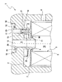
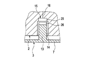
図1及び図2に示すように、フィルタ装置1は、フィルタエレメント3を収容するように構成されたフィルタハウジング2を備える。フィルタハウジング2は、濾過前側の入口4及び濾過後側の出口5を有する。フィルタ装置1は、特に自動車に配置され得る内燃機関の液体を濾過する役割を果たす。特に、フィルタ装置1は、内燃機関の潤滑油を濾過する役割を果たす。また、原則として、実施形態は、フィルタ装置1が内燃機関の燃料又は他のいずれかの液体を濾過する役割を果たすことが考えられる。
As shown in FIGS. 1 and 2, the filter device 1 includes a
フィルタエレメント3は、環状フィルタエレメントとして好ましくは設計され、それに合うように環状であるか円筒状のフィルタ体6を備えている。フィルタ体6は、例えば通常の濾過材料(例えば濾紙又は濾過フリース)からなる。図1及び図2に示すように、軸方向端部で、フィルタエレメント3は、液体が浸透しないような方法でフィルタ体6と接続されたエンドディスク7を備える。エンドディスク7は、フィルタ体6に溶接、接着その他のいかなる適切な方法でも接続され得る。例えば、フィルタ体6の濾過材料は、エンドディスク7に弾性変形して挿入され得る。図示されたエンドディスク7は、中央の開口部8を有する、開いたエンドディスク7である。軸方向他端で、フィルタエレメント3は、開閉され得る更なるエンドディスクを含むことができる。フィルタハウジング2の中で、フィルタエレメント3は、濾過前室9を濾過後室10から切り離す。濾過後室10が出口5と連通するのに対して、濾過前室9は入口4と連通する。一例として、濾過後室10は、フィルタ体6によって囲まれるフィルタエレメント3の内部に形成される。一例として、流れは、このように外側から内向きに放射状にフィルタエレメント3を通過できる。フィルタハウジング2は、適合する開口部8を有する開いたエンドディスク7が取り付けられ得るポート11を有する。出口5は、このように濾過後室10を有するフィルタエレメント3の内部を有するポート11を通って連通する。開いたエンドディスク7に、半径方向シール36が一体的に形成され、それはポート11と相互にシール作用を発揮する。
The filter element 3 is preferably designed as an annular filter element and comprises an annular or
フィルタエレメント3は、その縦中央軸12に関して軸方向に且つ偏心して突出するプラグ13を備えている。好ましくは、このプラグ13は、エンドディスク7に形成される。例えば、プラグ13は、エンドディスク7に一体的に形成される。また、プラグ13をエンドディスク7に、完全に又は部分的に取り付けることができる。
The filter element 3 includes a
ハウジング2は、プラグレセプタクル14を有する。ハウジング2は、濾過前室9の方へ開いている。フィルタエレメント3がフィルタハウジング2に適切に挿入されるときに、プラグ13がプラグレセプタクル14側へ軸方向に突出するか又はプラグレセプタクル14に詰め込まれるように、フィルタハウジング2とフィルタエレメント3とが互いに適合される。
The
加えて、フィルタ装置1は、それがプラグレセプタクル14のプラグ13の欠如及び存在の少なくとも一方を認識することができ、必要に応じて電気信号を送ることができるように構成されて配置される少なくとも1つの信号発生器15を備えている。例えば、ここで示されないコントローラに、各信号発生器15を、各信号回線16を介して接続することができる。
In addition, the filter device 1 is at least arranged and arranged so that it can recognize at least one of the absence and presence of the
図1に示す実施形態において、プラグレセプタクル14は、有底穴として形成される。特に、プラグ13を収容する機能の他に、この有底穴、すなわちプラグレセプタクル14は、更なる機能を有しない。対照的に、図2は、プラグレセプタクル14が、濾過前室9と連通するリターンライン又はドレーンライン17の入口領域により形成される実施形態を示す。ここで、プラグ13は、リターンライン又はドレーンライン17の入口領域に差し込まれるときに、ドレーンライン又はリターンライン17を閉じるための付加的な機能を成し遂げる。このために、プラグ13は、例えば、Oリングである対応する半径方向シール31を備えることができる。
In the embodiment shown in FIG. 1, the
以下に、信号発生器の複数の異なる、単なる具体例としての実施形態は、図1に示す実施形態における、有底穴として形成されるプラグレセプタクル14や、図2に示す実施形態における、リターンラインかドレーンライン17の入口領域により形成されるプラグレセプタクル14で図示され、累積的に結合したり、代替的に結合したり、任意に結合したりして実現することができる。
In the following, a plurality of different and merely exemplary embodiments of the signal generator include the
図1によれば、信号発生器15は、ホール・センサ18を含むことができる。プラグ13に接点素子19を取り付けることができ、その接近をホール・センサ18により検出することができる。接点素子19は、例えば、磁石本体又は金属本体を含むことができる。
According to FIG. 1, the
図2によれば、信号発生器15は、付加的に又は代わりに圧力センサ20を備えることができる。圧力センサ20は、リターンライン又はドレーンライン17に配置され、ドレーンライン17又はリターンライン17の液体の圧力を検出することができる。検出圧力が、既定値に達する場合、制御ロジックは、プラグ13がない、又は、フィルタエレメント3全体がないと推定する。圧力増加が、ドレーンライン17又はリターンライン17で発生しない場合、制御ロジックはプラグ13が適切にドレーンライン17又はリターンライン17の入口領域14を閉じていると推定する。従って、フィルタエレメント3は、なければならない。
According to FIG. 2, the
図3に示す変形例において、信号発生器15は、プラグ13と物理的に接触するボタン22によって作動できるスイッチ21を備えることができる。ボタン22は軸方向に変位可能な方法で取り付けられ、例えば、バネ24によってプレストレスをかけられ、プラグレセプタクル14に突出するアクチュエータ23を備えている。プラグ13が欠如しているときに、例えば、スイッチ21は閉じられ、それによってプラグ13及びそれを伴うフィルタエレメント3の欠如信号が送られる。プラグ13がプラグレセプタクル14に差し込まれていると、スイッチ21は開いて、フィルタエレメント3の存在信号を送る。異なる実施形態では、スイッチ21は、プラグ13がプラグレセプタクル14に挿入されているときにだけ閉じ、プラグ13が欠如しているときに開くことは、明らかである。
In the variant shown in FIG. 3, the
図4に示す実施形態において、信号発生器は、磁力により作動可能なリードコンタクト25を含むことができる。このため、プラグは、永久磁石26を備えることができる。
In the embodiment shown in FIG. 4, the signal generator can include a
図5によれば、信号発生器15に無線データ交換のためのRFIDトランスポンダ27と通信できるRFIDトランスポンダリーダ28を設けることができる。このため、上記RFIDトランスポンダ27は、プラグ13内に配置される。トランスポンダリーダ28は、フィルタハウジング2内の適切な位置に配置される。RFIDトランスポンダ27によって、リーダ28は、少なくとも、特定のフィルタエレメント3があるという情報を読むことができる。さらにまた、RFIDトランスポンダ27によって、付加的なデータ及び情報、例えばフィルタエレメント3の製造場所及び製造年月日並びにフィルタエレメント3の正確なタイプ指定を伝達することができるようにすることもできる。
According to FIG. 5, the
図1及び図2によれば、信号発生器15は、出口5に配置され、出口5の中の液体の圧力を検出することができる圧力センサ29を含むこともできる。出口5の中の圧力が既定値まで上昇する場合、制御ロジックは、ドレーンライン17又はリターンライン17が閉じられており、プラグ13を有する適切なフィルタエレメント3が存在していると仮定する。出口5に所定の圧力増加が発生しない場合、制御ロジックは、リターンライン17又はドレーンライン17が開いており、フィルタエレメント3が欠如している、フィルタエレメント3が適切に挿入されていない、又は、間違ったフィルタエレメント3が挿入されいると推定する。
According to FIGS. 1 and 2, the
特に有利な実施形態によれば、フィルタエレメント3が欠如しているときでも、入口4を通ってそれぞれの液体を届ける供給装置が、内燃機関の緊急供給に充分である出口5を通る液体の量を分配することができるように、リターンライン17又はドレーンライン17を絞ることができる。例えば、フィルタエレメント3が欠如しているときでも、このように、一時的に内燃機関の緊急供給を確実にする緊急ボリューム・フローを分配できる。この緊急動作のために、適切な制御は内燃機関のための特に減少するパフォーマンス・データを特定できる。それにより、例えば、車両が最大限のパフォーマンスででなく、非常に削減されたパフォーマンスだけで、少なくとも故障対応工場へ移動できるように構成することができる。
According to a particularly advantageous embodiment, the amount of liquid through the outlet 5 in which the supply device that delivers the respective liquid through the inlet 4 is sufficient for the emergency supply of the internal combustion engine, even when the filter element 3 is absent. So that the
図1及び図2に示す実施形態において、フィルタエレメント3は、フィルタハウジング2の中で吊り下げられて配置される。フィルタハウジング2内でフィルタエレメント3が起立して配置されることも主に可能でもあることは明らかである。更に、フィルタハウジング2内でフィルタエレメント3を横たわった状態で配置することもできる。
In the embodiment shown in FIGS. 1 and 2, the filter element 3 is arranged suspended in the
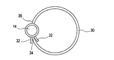
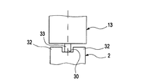
図1及び図2によれば、ハウジング2は、傾斜路30を含むことができる。傾斜路30は、迂回形状で、プラグレセプタクル14の方へ誘導する。ここで、傾斜路30は、プラグレセプタクル14の方へ螺旋状に下降する。フィルタエレメント3にねじ込まれるときに、プラグ13は傾斜路30に沿ってスライド移動できる。傾斜路30によって、プラグレセプタクル14へのプラグ13の挿入が著しく単純化される。
According to FIGS. 1 and 2, the
フィルタハウジング2が、この種の傾斜路30を備えていれば、特に、図6〜図8において更に詳細に説明される特別な実施形態を備えることができる。これらの特別な実施形態において、傾斜路30及びプラグ13は、キー・ロック原理に従って相互作用して適合するように形成される。このキー・ロック原理は、プラグ13が傾斜路30に特に適合されるフィルタエレメント3だけがフィルタ装置1で適切に用いられることができるようにする、という効果を奏する。関連した適切な使用により、フィルタエレメント3を取り付けるか又は回転させるときに、プラグ13がプラグレセプタクル14を発見して自動的に閉じてプラグレセプタクル14に貫入されることができる。フィルタ装置1に特に適合されないフィルタエレメント3の場合には、キー・ロック原理は、フィルタエレメント3にねじ込まれるときに、現在のプラグ13が自動的にプラグレセプタクル14を捜し出すことができる可能性をなくす。そして、これによって、フィルタ装置1に正確に適合するフィルタエレメント3だけを使用することができ、例えば、適当な濾過器機能を確実に行うことができる、ということを達成することを意図する。
If the
このキー・ロック原理を実現するために、図6〜図8によれば、案内本体32を有する挿入輪郭を設けることができ、それは傾斜路30の片側又は両側に配置することができ、それは傾斜路30を越えて軸方向に突出する。プラグ13は、案内本体32に適合されてそれぞれのプラグ13から軸方向に突出する突起33を有する場合にだけ、傾斜路30に沿って低い方へスライドしてプラグレセプタクル14に到達することができる。例えば、この突起33は、プラグ13と傾斜路30とが接触できるように、先細り形状か、ピン形状か、又はリブ形状の突起である。この突起33は、案内本体32を横切ってプラグ13を持上げることができるように、軸方向に必要な大きさにされる。これは、傾斜路30上の突起33を経てスライドするプラグ13が、プラグレセプタクル14と距離をとって案内本体32に沿って通過する方向に向けることができるように、案内本体32から間隔を置いて配置されることを意味する。図6〜図8によれば、プラグ13をスライドさせることを許容することで、案内本体32の間及び案内本体32を通って、突起33が傾斜路30に接触することができる。
In order to realize this key-lock principle, according to FIGS. 6 to 8, an insertion profile with a guiding
図6によれば、案内本体32は、より低い傾斜路端34の領域に配置される。プラグレセプタクル14は、より低い傾斜路端34と、このより低い傾斜路端34の方へ傾斜路30に沿って下降する上方の傾斜路端35との間に円周方向に配置される。
According to FIG. 6, the
それはさておき、キー・ロック原理及びその実施に関し、上述した特許文献1が参照され、明示的な参照によって本発明の開示内容に加えられる。 Aside from that, with respect to the key lock principle and its implementation, reference is made to the above-mentioned patent document 1, which is added to the disclosure content of the present invention by explicit reference.
Claims (1)
上記フィルタハウジング(2)が濾過前側の入口(4)及び濾過後側の出口(5)を有し、
上記フィルタエレメント(3)が上記フィルタハウジング(2)に挿入された挿入状態において上記フィルタエレメント(3)が上記出口(5)と連通する濾過後室(10)から上記入口(4)と連通する濾過前室(9)を切り離し、
上記フィルタエレメント(3)が軸方向に延び且つ上記フィルタエレメント(3)に対して偏心して突出するプラグ(13)を有し、上記挿入状態において、上記フィルタハウジング(2)内に形成されたプラグレセプタクル(14)に上記プラグ(13)が差し込まれる、自動車の内燃機関の液体を濾過するためのフィルタ装置であって、
上記プラグレセプタクル(14)は有底穴として形成され、該プラグレセプタクル(14)には、上記プラグ(13)が存在するか及び存在しないかの少なくとも一方を認識できて信号を送ることができるように、リードコンタクト(25)、RFIDトランスポンダリーダ(28)、ホールセンサ(18)又はスイッチ(21)を有する、少なくとも1つの信号発生器(15)が設けられており、
上記フィルタエレメント(3)が欠如しているときに、上記信号発生器(15)からの該フィルタエレメント(3)の欠如を報せる信号を受けて上記濾過前室(9)と連通するリターンライン(17)又はドレンライン(17)から流出する上記液体の量を制限して一時的に上記内燃機関に対して緊急供給を確実にする緊急ボリューム・フローを上記出口(5)を通って上記内燃機関に分配することができるように、上記リターンライン(17)又は上記ドレンライン(17)が絞られるように構成されている
ことを特徴とするフィルタ装置。 A filter housing (2) for accommodating the filter element (3);
The filter housing (2) has an inlet (4) on the front side of filtration and an outlet (5) on the rear side of filtration,
In the inserted state in which the filter element (3) is inserted into the filter housing (2), the filter element (3) communicates with the inlet (4) from the post-filtration chamber (10) that communicates with the outlet (5). Cut off the pre-filter chamber (9)
The filter element (3) has a plug (13) extending in the axial direction and protruding eccentrically with respect to the filter element (3 ), and is formed in the filter housing (2) in the inserted state. A filter device for filtering liquid of an internal combustion engine of an automobile, wherein the plug (13) is inserted into a receptacle (14),
The plug receptacle (14) is formed as a bottomed hole so that at least one of the presence or absence of the plug (13) can be recognized and a signal can be transmitted to the plug receptacle (14). At least one signal generator (15) having a lead contact (25), an RFID transponder reader (28), a Hall sensor (18) or a switch (21) ,
When the upper Symbol filter element (3) is absent, return to communication with the pre-filtration chamber (9) receives a signal informing the absence of the filter element (3) from the signal generator (15) line (17) or the emergency volume flow to ensure emergency supplied to temporarily the internal combustion engine by limiting the amount of the liquid flowing out of the de Renrain (17) through said outlet (5) A filter device characterized in that the return line (17) or the drain line (17) is restricted so that it can be distributed to the internal combustion engine.
Applications Claiming Priority (3)
| Application Number | Priority Date | Filing Date | Title |
|---|---|---|---|
| DE102007062102.9 | 2007-12-21 | ||
| DE102007062102A DE102007062102A1 (en) | 2007-12-21 | 2007-12-21 | filtering device |
| PCT/EP2008/066751 WO2009080455A1 (en) | 2007-12-21 | 2008-12-04 | Filter device |
Publications (2)
| Publication Number | Publication Date |
|---|---|
| JP2011506842A JP2011506842A (en) | 2011-03-03 |
| JP5227420B2 true JP5227420B2 (en) | 2013-07-03 |
Family
ID=40561732
Family Applications (1)
| Application Number | Title | Priority Date | Filing Date |
|---|---|---|---|
| JP2010538548A Expired - Fee Related JP5227420B2 (en) | 2007-12-21 | 2008-12-04 | Filter device |
Country Status (9)
| Country | Link |
|---|---|
| US (1) | US9555351B2 (en) |
| EP (1) | EP2222384B1 (en) |
| JP (1) | JP5227420B2 (en) |
| KR (1) | KR101515526B1 (en) |
| CN (1) | CN101903078B (en) |
| BR (1) | BRPI0821722B1 (en) |
| DE (1) | DE102007062102A1 (en) |
| PL (1) | PL2222384T3 (en) |
| WO (1) | WO2009080455A1 (en) |
Cited By (1)
| Publication number | Priority date | Publication date | Assignee | Title |
|---|---|---|---|---|
| KR20170128594A (en) * | 2015-04-21 | 2017-11-22 | 말레 인터내셔널 게엠베하 | Filter device |
Families Citing this family (33)
| Publication number | Priority date | Publication date | Assignee | Title |
|---|---|---|---|---|
| DE102007062100A1 (en) * | 2007-12-21 | 2009-06-25 | Mahle International Gmbh | Liquid filter, in particular oil filter |
| DE102009041523B4 (en) | 2009-09-15 | 2024-01-25 | Mahle International Gmbh | Filter device |
| DE102009049868A1 (en) * | 2009-10-20 | 2011-04-21 | Mahle International Gmbh | filtering device |
| KR101141472B1 (en) * | 2009-11-27 | 2012-05-07 | 엘지전자 주식회사 | Water dispensor with detecting means for filter replacement |
| KR101764925B1 (en) | 2010-10-08 | 2017-08-03 | 엘지이노텍 주식회사 | Anti-seperating structure of sensing magnet for eps motor |
| US9707497B2 (en) | 2011-11-21 | 2017-07-18 | Saint-Gobain Performance Plastics Corporation | Modular stacked disc filter apparatus |
| US11975279B2 (en) * | 2012-01-12 | 2024-05-07 | Davco Technology, Llc | Fluid filter assembly with a filter cartridge and housing interface |
| DE102012000876C5 (en) * | 2012-01-19 | 2014-10-02 | Mann+Hummel Gmbh | Liquid filter and filter element of a liquid filter |
| US20130220900A1 (en) * | 2012-02-27 | 2013-08-29 | Cummins Filtration Ip, Inc. | Filter communication and identification network |
| CA2867629C (en) * | 2012-04-19 | 2017-11-07 | Outotec (Finland) Oy | Method for filtering a suspension and filter plate |
| JP6181175B2 (en) * | 2012-06-25 | 2017-08-16 | エイヴィエル・テスト・システムズ・インコーポレーテッド | Emission measurement equipment and method |
| DE102013009198B4 (en) * | 2013-06-03 | 2021-06-10 | Mann+Hummel Gmbh | Filter for fluid and method of assembling a filter element in a filter housing |
| DE112015004896T5 (en) * | 2014-12-18 | 2017-08-10 | Cummins Filtration Ip, Inc. | Automatic drain plug for a filtration device |
| CN107921336B (en) | 2015-08-31 | 2021-04-06 | 康明斯过滤Ip公司 | Filter port seal |
| DE102016001023A1 (en) * | 2016-02-01 | 2017-08-03 | Mann + Hummel Gmbh | Filter element and fluid filter |
| DE102016203764A1 (en) | 2016-03-08 | 2017-09-14 | Mahle International Gmbh | filtering device |
| DE102017000976A1 (en) | 2017-02-03 | 2018-08-09 | Mann + Hummel Gmbh | Filter element, filter system with a filter element and method for producing a filter element |
| JP7082874B2 (en) * | 2017-12-26 | 2022-06-09 | ヤマシンフィルタ株式会社 | Filter device |
| EP3608009A1 (en) | 2018-08-10 | 2020-02-12 | Mann+Hummel GmbH | Filter system and filter element with improved positioning means |
| DE102018218632A1 (en) | 2018-10-31 | 2020-04-30 | Mahle International Gmbh | Filter device |
| DE102018221262A1 (en) | 2018-12-07 | 2020-06-10 | Mahle International Gmbh | Filter element for a filter device |
| DE102018221256A1 (en) * | 2018-12-07 | 2020-06-10 | Mahle International Gmbh | Filter element for a filter device |
| USD967330S1 (en) | 2019-03-21 | 2022-10-18 | Mahle International Gmbh | Pin for a filter element |
| US11992788B2 (en) | 2019-06-27 | 2024-05-28 | Mahle International Gmbh | Filter device |
| US11426687B2 (en) | 2019-06-27 | 2022-08-30 | Mahle International Gmbh | Fuel filter |
| US11452956B2 (en) | 2019-06-27 | 2022-09-27 | Mahle International Gmbh | Fuel filter |
| JP7305518B2 (en) * | 2019-11-08 | 2023-07-10 | ヤマシンフィルタ株式会社 | filter device |
| USD969964S1 (en) | 2020-03-06 | 2022-11-15 | Pentair Residential Filtration, Llc | Filtration system |
| US11511217B2 (en) | 2020-09-22 | 2022-11-29 | Mahle International Gmbh | Filter and method of fabricating same |
| USD958288S1 (en) | 2020-10-09 | 2022-07-19 | Mahle International Gmbh | Filter device |
| CN112459936A (en) * | 2020-11-25 | 2021-03-09 | 蚌埠金威滤清器有限公司 | Diesel filter assembly for engineering vehicles and machines |
| DE102021209336B4 (en) | 2021-08-25 | 2024-04-25 | Filtration Group Gmbh | Filter device for filtering a liquid and associated filter element |
| JP2023109619A (en) * | 2022-01-27 | 2023-08-08 | ヤマシンフィルタ株式会社 | Filter apparatus |
Family Cites Families (15)
| Publication number | Priority date | Publication date | Assignee | Title |
|---|---|---|---|---|
| US4384474A (en) * | 1980-10-30 | 1983-05-24 | Amf Incorporated | Method and apparatus for testing and using membrane filters in an on site of use housing |
| JPS6238215A (en) | 1985-08-09 | 1987-02-19 | Aisin Seiki Co Ltd | Apparatus for detecting clogging of filter |
| JP3834402B2 (en) | 1997-11-11 | 2006-10-18 | 東京濾器株式会社 | Oil filter |
| DE19951085A1 (en) | 1999-10-23 | 2001-04-26 | Mahle Filtersysteme Gmbh | Lubricating oil cleaning filter, with ramp on floor of receiving cavity |
| JP2001205021A (en) * | 2000-01-28 | 2001-07-31 | Amada Co Ltd | Fail-safe mechanism of high pressure filter |
| JP2002205061A (en) * | 2001-01-15 | 2002-07-23 | Toray Ind Inc | Water cleaning device |
| JP4012408B2 (en) | 2002-02-12 | 2007-11-21 | 株式会社日立製作所 | Oil filter |
| US7638042B2 (en) * | 2002-02-15 | 2009-12-29 | 3M Innovative Properties Company | System for monitoring the performance of fluid treatment cartridges |
| ATE337060T1 (en) * | 2002-11-06 | 2006-09-15 | Donaldson Co Inc | FILTER CARTRIDGE FOR OPERATION WITH A SENSOR SYSTEM |
| JP2004238853A (en) | 2003-02-04 | 2004-08-26 | Sumitomo (Shi) Construction Machinery Manufacturing Co Ltd | Oil filter condition display device for construction machine |
| US7060184B2 (en) * | 2003-05-21 | 2006-06-13 | Arvin Technologies, Inc. | Quick-drain valve member for use with filter apparatus |
| JP2007537870A (en) * | 2004-05-20 | 2007-12-27 | ドナルドソン カンパニー,インコーポレイティド | Filter assembly having an antenna |
| CN101014398A (en) * | 2004-05-20 | 2007-08-08 | 唐纳森公司 | Filter assembly having antenna |
| JP2006007140A (en) | 2004-06-28 | 2006-01-12 | Yamashin-Filter Corp | Filtering device |
| DE102006028148A1 (en) * | 2006-06-16 | 2007-12-20 | Mahle International Gmbh | Fuel filter |
-
2007
- 2007-12-21 DE DE102007062102A patent/DE102007062102A1/en not_active Ceased
-
2008
- 2008-12-04 WO PCT/EP2008/066751 patent/WO2009080455A1/en active Application Filing
- 2008-12-04 CN CN200880121874.5A patent/CN101903078B/en not_active Expired - Fee Related
- 2008-12-04 EP EP08864848.0A patent/EP2222384B1/en not_active Not-in-force
- 2008-12-04 BR BRPI0821722-0A patent/BRPI0821722B1/en not_active IP Right Cessation
- 2008-12-04 US US12/809,198 patent/US9555351B2/en not_active Expired - Fee Related
- 2008-12-04 KR KR1020107014728A patent/KR101515526B1/en active IP Right Grant
- 2008-12-04 JP JP2010538548A patent/JP5227420B2/en not_active Expired - Fee Related
- 2008-12-04 PL PL08864848T patent/PL2222384T3/en unknown
Cited By (4)
| Publication number | Priority date | Publication date | Assignee | Title |
|---|---|---|---|---|
| KR20170128594A (en) * | 2015-04-21 | 2017-11-22 | 말레 인터내셔널 게엠베하 | Filter device |
| KR20180018832A (en) * | 2015-04-21 | 2018-02-21 | 말레 인터내셔널 게엠베하 | Filter device |
| KR101894692B1 (en) * | 2015-04-21 | 2018-09-04 | 말레 인터내셔널 게엠베하 | Filter device |
| KR102005022B1 (en) * | 2015-04-21 | 2019-10-01 | 말레 인터내셔널 게엠베하 | Filter device |
Also Published As
| Publication number | Publication date |
|---|---|
| WO2009080455A1 (en) | 2009-07-02 |
| BRPI0821722A2 (en) | 2015-06-16 |
| CN101903078B (en) | 2014-05-07 |
| JP2011506842A (en) | 2011-03-03 |
| KR101515526B1 (en) | 2015-04-27 |
| US20110089091A1 (en) | 2011-04-21 |
| KR20100098427A (en) | 2010-09-06 |
| EP2222384A1 (en) | 2010-09-01 |
| US9555351B2 (en) | 2017-01-31 |
| CN101903078A (en) | 2010-12-01 |
| BRPI0821722B1 (en) | 2019-04-02 |
| DE102007062102A1 (en) | 2009-06-25 |
| PL2222384T3 (en) | 2018-07-31 |
| EP2222384B1 (en) | 2018-02-14 |
Similar Documents
| Publication | Publication Date | Title |
|---|---|---|
| JP5227420B2 (en) | Filter device | |
| US20130062270A1 (en) | Filter appliance | |
| JP5325894B2 (en) | Liquid filter, especially oil filter | |
| US10371108B2 (en) | Fuel filter | |
| US7392783B2 (en) | Internal combustion engine, especially in a motor vehicle, having a fuel filter system | |
| EP1058000B1 (en) | Fuel transfer and conditioning unit | |
| US6361684B1 (en) | Integrated fuel pump and fuel filter with fuel-water separation | |
| US11975279B2 (en) | Fluid filter assembly with a filter cartridge and housing interface | |
| CN101534919B (en) | A water draining system for a fuel filter | |
| US10220338B2 (en) | Electronic filter detection feature for liquid filtration systems | |
| US20080164188A1 (en) | Fuel filter | |
| ITRE20000062A1 (en) | PERFECTED AUTOMATIC GROUP FOR THE PURIFICATION OF WATER ACCUMULATED IN A VEHICLE FUEL FILTER, TYPICALLY FOR DIESEL ENGINES | |
| JP6648274B2 (en) | Oil filter and filter cartridge for automotive oil filter | |
| CN112261983B (en) | Air filter housing with closing device, air filter and vehicle | |
| EP1290334B1 (en) | Filter for diesel engine fuel | |
| US20090145825A1 (en) | Filter Arrangement for Liquids | |
| CN111386145A (en) | Filter element for a liquid filter, filter and filter housing | |
| CN205744047U (en) | Automobile oil filter failure alarm device |
Legal Events
| Date | Code | Title | Description |
|---|---|---|---|
| A621 | Written request for application examination |
Free format text: JAPANESE INTERMEDIATE CODE: A621 Effective date: 20110908 |
|
| A131 | Notification of reasons for refusal |
Free format text: JAPANESE INTERMEDIATE CODE: A131 Effective date: 20120515 |
|
| A977 | Report on retrieval |
Free format text: JAPANESE INTERMEDIATE CODE: A971007 Effective date: 20120517 |
|
| A521 | Written amendment |
Free format text: JAPANESE INTERMEDIATE CODE: A523 Effective date: 20120713 |
|
| RD02 | Notification of acceptance of power of attorney |
Free format text: JAPANESE INTERMEDIATE CODE: A7422 Effective date: 20120713 |
|
| A131 | Notification of reasons for refusal |
Free format text: JAPANESE INTERMEDIATE CODE: A131 Effective date: 20120925 |
|
| A521 | Written amendment |
Free format text: JAPANESE INTERMEDIATE CODE: A523 Effective date: 20121214 |
|
| TRDD | Decision of grant or rejection written | ||
| A01 | Written decision to grant a patent or to grant a registration (utility model) |
Free format text: JAPANESE INTERMEDIATE CODE: A01 Effective date: 20130219 |
|
| A61 | First payment of annual fees (during grant procedure) |
Free format text: JAPANESE INTERMEDIATE CODE: A61 Effective date: 20130315 |
|
| R150 | Certificate of patent or registration of utility model |
Ref document number: 5227420 Country of ref document: JP Free format text: JAPANESE INTERMEDIATE CODE: R150 Free format text: JAPANESE INTERMEDIATE CODE: R150 |
|
| FPAY | Renewal fee payment (event date is renewal date of database) |
Free format text: PAYMENT UNTIL: 20160322 Year of fee payment: 3 |
|
| R250 | Receipt of annual fees |
Free format text: JAPANESE INTERMEDIATE CODE: R250 |
|
| R250 | Receipt of annual fees |
Free format text: JAPANESE INTERMEDIATE CODE: R250 |
|
| R250 | Receipt of annual fees |
Free format text: JAPANESE INTERMEDIATE CODE: R250 |
|
| R250 | Receipt of annual fees |
Free format text: JAPANESE INTERMEDIATE CODE: R250 |
|
| LAPS | Cancellation because of no payment of annual fees |