JP5227170B2 - Device for placing a stent in a small hole - Google Patents
Device for placing a stent in a small hole Download PDFInfo
- Publication number
- JP5227170B2 JP5227170B2 JP2008513676A JP2008513676A JP5227170B2 JP 5227170 B2 JP5227170 B2 JP 5227170B2 JP 2008513676 A JP2008513676 A JP 2008513676A JP 2008513676 A JP2008513676 A JP 2008513676A JP 5227170 B2 JP5227170 B2 JP 5227170B2
- Authority
- JP
- Japan
- Prior art keywords
- inflatable
- distal end
- proximal end
- prosthesis
- proximal
- Prior art date
- Legal status (The legal status is an assumption and is not a legal conclusion. Google has not performed a legal analysis and makes no representation as to the accuracy of the status listed.)
- Active
Links
- 239000000463 material Substances 0.000 claims description 18
- 239000012530 fluid Substances 0.000 claims description 13
- 210000004204 blood vessel Anatomy 0.000 claims description 9
- 230000000452 restraining effect Effects 0.000 claims description 6
- 239000013013 elastic material Substances 0.000 claims description 5
- 230000003902 lesion Effects 0.000 description 36
- 238000000034 method Methods 0.000 description 23
- 239000012528 membrane Substances 0.000 description 10
- 210000005166 vasculature Anatomy 0.000 description 6
- 239000004033 plastic Substances 0.000 description 5
- 229920003023 plastic Polymers 0.000 description 5
- 150000001875 compounds Chemical class 0.000 description 4
- -1 for example Substances 0.000 description 4
- 208000031481 Pathologic Constriction Diseases 0.000 description 3
- 230000000916 dilatatory effect Effects 0.000 description 3
- 229910052751 metal Inorganic materials 0.000 description 3
- 239000002184 metal Substances 0.000 description 3
- 230000036262 stenosis Effects 0.000 description 3
- 208000037804 stenosis Diseases 0.000 description 3
- 229920002994 synthetic fiber Polymers 0.000 description 3
- 238000003466 welding Methods 0.000 description 3
- IJGRMHOSHXDMSA-UHFFFAOYSA-N Atomic nitrogen Chemical compound N#N IJGRMHOSHXDMSA-UHFFFAOYSA-N 0.000 description 2
- 239000004698 Polyethylene Substances 0.000 description 2
- FAPWRFPIFSIZLT-UHFFFAOYSA-M Sodium chloride Chemical compound [Na+].[Cl-] FAPWRFPIFSIZLT-UHFFFAOYSA-M 0.000 description 2
- 238000004026 adhesive bonding Methods 0.000 description 2
- 239000008280 blood Substances 0.000 description 2
- 210000004369 blood Anatomy 0.000 description 2
- 210000004351 coronary vessel Anatomy 0.000 description 2
- 239000010408 film Substances 0.000 description 2
- 238000002594 fluoroscopy Methods 0.000 description 2
- 238000012986 modification Methods 0.000 description 2
- 230000004048 modification Effects 0.000 description 2
- HLXZNVUGXRDIFK-UHFFFAOYSA-N nickel titanium Chemical compound [Ti].[Ti].[Ti].[Ti].[Ti].[Ti].[Ti].[Ti].[Ti].[Ti].[Ti].[Ni].[Ni].[Ni].[Ni].[Ni].[Ni].[Ni].[Ni].[Ni].[Ni].[Ni].[Ni].[Ni].[Ni] HLXZNVUGXRDIFK-UHFFFAOYSA-N 0.000 description 2
- 229910001000 nickel titanium Inorganic materials 0.000 description 2
- BASFCYQUMIYNBI-UHFFFAOYSA-N platinum Chemical compound [Pt] BASFCYQUMIYNBI-UHFFFAOYSA-N 0.000 description 2
- 229920000573 polyethylene Polymers 0.000 description 2
- 229920002635 polyurethane Polymers 0.000 description 2
- 239000004814 polyurethane Substances 0.000 description 2
- 230000005855 radiation Effects 0.000 description 2
- 229910052710 silicon Inorganic materials 0.000 description 2
- 239000010703 silicon Substances 0.000 description 2
- 239000011780 sodium chloride Substances 0.000 description 2
- 239000000126 substance Substances 0.000 description 2
- 230000001225 therapeutic effect Effects 0.000 description 2
- 229910001226 L605 Inorganic materials 0.000 description 1
- 239000004677 Nylon Substances 0.000 description 1
- 229920002614 Polyether block amide Polymers 0.000 description 1
- 230000001154 acute effect Effects 0.000 description 1
- 229910045601 alloy Inorganic materials 0.000 description 1
- 239000000956 alloy Substances 0.000 description 1
- 210000003484 anatomy Anatomy 0.000 description 1
- 239000011230 binding agent Substances 0.000 description 1
- 230000037237 body shape Effects 0.000 description 1
- 210000001715 carotid artery Anatomy 0.000 description 1
- 238000003486 chemical etching Methods 0.000 description 1
- 238000006243 chemical reaction Methods 0.000 description 1
- 239000011248 coating agent Substances 0.000 description 1
- 238000000576 coating method Methods 0.000 description 1
- 239000002872 contrast media Substances 0.000 description 1
- 238000005520 cutting process Methods 0.000 description 1
- 230000007423 decrease Effects 0.000 description 1
- 230000007850 degeneration Effects 0.000 description 1
- 230000002708 enhancing effect Effects 0.000 description 1
- 229920000295 expanded polytetrafluoroethylene Polymers 0.000 description 1
- 210000001105 femoral artery Anatomy 0.000 description 1
- 239000000835 fiber Substances 0.000 description 1
- PCHJSUWPFVWCPO-UHFFFAOYSA-N gold Chemical compound [Au] PCHJSUWPFVWCPO-UHFFFAOYSA-N 0.000 description 1
- 229910052737 gold Inorganic materials 0.000 description 1
- 239000010931 gold Substances 0.000 description 1
- 230000035876 healing Effects 0.000 description 1
- 238000010438 heat treatment Methods 0.000 description 1
- 230000002439 hemostatic effect Effects 0.000 description 1
- 238000003384 imaging method Methods 0.000 description 1
- 238000002513 implantation Methods 0.000 description 1
- 238000003780 insertion Methods 0.000 description 1
- 230000037431 insertion Effects 0.000 description 1
- 229910052741 iridium Inorganic materials 0.000 description 1
- GKOZUEZYRPOHIO-UHFFFAOYSA-N iridium atom Chemical compound [Ir] GKOZUEZYRPOHIO-UHFFFAOYSA-N 0.000 description 1
- 238000003698 laser cutting Methods 0.000 description 1
- 239000007788 liquid Substances 0.000 description 1
- 238000003754 machining Methods 0.000 description 1
- 238000004519 manufacturing process Methods 0.000 description 1
- 238000002844 melting Methods 0.000 description 1
- 230000008018 melting Effects 0.000 description 1
- 238000012544 monitoring process Methods 0.000 description 1
- 229910052758 niobium Inorganic materials 0.000 description 1
- 239000010955 niobium Substances 0.000 description 1
- GUCVJGMIXFAOAE-UHFFFAOYSA-N niobium atom Chemical compound [Nb] GUCVJGMIXFAOAE-UHFFFAOYSA-N 0.000 description 1
- 229910052757 nitrogen Inorganic materials 0.000 description 1
- 229920001778 nylon Polymers 0.000 description 1
- 230000002093 peripheral effect Effects 0.000 description 1
- 229910052697 platinum Inorganic materials 0.000 description 1
- 229920000139 polyethylene terephthalate Polymers 0.000 description 1
- 229920001343 polytetrafluoroethylene Polymers 0.000 description 1
- 239000004810 polytetrafluoroethylene Substances 0.000 description 1
- 238000003825 pressing Methods 0.000 description 1
- 238000002271 resection Methods 0.000 description 1
- 239000012858 resilient material Substances 0.000 description 1
- 239000012781 shape memory material Substances 0.000 description 1
- 239000010935 stainless steel Substances 0.000 description 1
- 229910001220 stainless steel Inorganic materials 0.000 description 1
- 238000001356 surgical procedure Methods 0.000 description 1
- 229910052715 tantalum Inorganic materials 0.000 description 1
- GUVRBAGPIYLISA-UHFFFAOYSA-N tantalum atom Chemical compound [Ta] GUVRBAGPIYLISA-UHFFFAOYSA-N 0.000 description 1
- 239000010409 thin film Substances 0.000 description 1
- 230000008467 tissue growth Effects 0.000 description 1
- 230000007704 transition Effects 0.000 description 1
- WFKWXMTUELFFGS-UHFFFAOYSA-N tungsten Chemical compound [W] WFKWXMTUELFFGS-UHFFFAOYSA-N 0.000 description 1
- 229910052721 tungsten Inorganic materials 0.000 description 1
- 239000010937 tungsten Substances 0.000 description 1
- 238000007794 visualization technique Methods 0.000 description 1
Images


Classifications
-
- A—HUMAN NECESSITIES
- A61—MEDICAL OR VETERINARY SCIENCE; HYGIENE
- A61F—FILTERS IMPLANTABLE INTO BLOOD VESSELS; PROSTHESES; DEVICES PROVIDING PATENCY TO, OR PREVENTING COLLAPSING OF, TUBULAR STRUCTURES OF THE BODY, e.g. STENTS; ORTHOPAEDIC, NURSING OR CONTRACEPTIVE DEVICES; FOMENTATION; TREATMENT OR PROTECTION OF EYES OR EARS; BANDAGES, DRESSINGS OR ABSORBENT PADS; FIRST-AID KITS
- A61F2/00—Filters implantable into blood vessels; Prostheses, i.e. artificial substitutes or replacements for parts of the body; Appliances for connecting them with the body; Devices providing patency to, or preventing collapsing of, tubular structures of the body, e.g. stents
- A61F2/82—Devices providing patency to, or preventing collapsing of, tubular structures of the body, e.g. stents
- A61F2/86—Stents in a form characterised by the wire-like elements; Stents in the form characterised by a net-like or mesh-like structure
- A61F2/90—Stents in a form characterised by the wire-like elements; Stents in the form characterised by a net-like or mesh-like structure characterised by a net-like or mesh-like structure
-
- A—HUMAN NECESSITIES
- A61—MEDICAL OR VETERINARY SCIENCE; HYGIENE
- A61F—FILTERS IMPLANTABLE INTO BLOOD VESSELS; PROSTHESES; DEVICES PROVIDING PATENCY TO, OR PREVENTING COLLAPSING OF, TUBULAR STRUCTURES OF THE BODY, e.g. STENTS; ORTHOPAEDIC, NURSING OR CONTRACEPTIVE DEVICES; FOMENTATION; TREATMENT OR PROTECTION OF EYES OR EARS; BANDAGES, DRESSINGS OR ABSORBENT PADS; FIRST-AID KITS
- A61F2/00—Filters implantable into blood vessels; Prostheses, i.e. artificial substitutes or replacements for parts of the body; Appliances for connecting them with the body; Devices providing patency to, or preventing collapsing of, tubular structures of the body, e.g. stents
- A61F2/95—Instruments specially adapted for placement or removal of stents or stent-grafts
- A61F2/958—Inflatable balloons for placing stents or stent-grafts
-
- A—HUMAN NECESSITIES
- A61—MEDICAL OR VETERINARY SCIENCE; HYGIENE
- A61F—FILTERS IMPLANTABLE INTO BLOOD VESSELS; PROSTHESES; DEVICES PROVIDING PATENCY TO, OR PREVENTING COLLAPSING OF, TUBULAR STRUCTURES OF THE BODY, e.g. STENTS; ORTHOPAEDIC, NURSING OR CONTRACEPTIVE DEVICES; FOMENTATION; TREATMENT OR PROTECTION OF EYES OR EARS; BANDAGES, DRESSINGS OR ABSORBENT PADS; FIRST-AID KITS
- A61F2/00—Filters implantable into blood vessels; Prostheses, i.e. artificial substitutes or replacements for parts of the body; Appliances for connecting them with the body; Devices providing patency to, or preventing collapsing of, tubular structures of the body, e.g. stents
- A61F2/82—Devices providing patency to, or preventing collapsing of, tubular structures of the body, e.g. stents
- A61F2002/821—Ostial stents
-
- A—HUMAN NECESSITIES
- A61—MEDICAL OR VETERINARY SCIENCE; HYGIENE
- A61F—FILTERS IMPLANTABLE INTO BLOOD VESSELS; PROSTHESES; DEVICES PROVIDING PATENCY TO, OR PREVENTING COLLAPSING OF, TUBULAR STRUCTURES OF THE BODY, e.g. STENTS; ORTHOPAEDIC, NURSING OR CONTRACEPTIVE DEVICES; FOMENTATION; TREATMENT OR PROTECTION OF EYES OR EARS; BANDAGES, DRESSINGS OR ABSORBENT PADS; FIRST-AID KITS
- A61F2250/00—Special features of prostheses classified in groups A61F2/00 - A61F2/26 or A61F2/82 or A61F9/00 or A61F11/00 or subgroups thereof
- A61F2250/0014—Special features of prostheses classified in groups A61F2/00 - A61F2/26 or A61F2/82 or A61F9/00 or A61F11/00 or subgroups thereof having different values of a given property or geometrical feature, e.g. mechanical property or material property, at different locations within the same prosthesis
- A61F2250/0039—Special features of prostheses classified in groups A61F2/00 - A61F2/26 or A61F2/82 or A61F9/00 or A61F11/00 or subgroups thereof having different values of a given property or geometrical feature, e.g. mechanical property or material property, at different locations within the same prosthesis differing in diameter
-
- A—HUMAN NECESSITIES
- A61—MEDICAL OR VETERINARY SCIENCE; HYGIENE
- A61F—FILTERS IMPLANTABLE INTO BLOOD VESSELS; PROSTHESES; DEVICES PROVIDING PATENCY TO, OR PREVENTING COLLAPSING OF, TUBULAR STRUCTURES OF THE BODY, e.g. STENTS; ORTHOPAEDIC, NURSING OR CONTRACEPTIVE DEVICES; FOMENTATION; TREATMENT OR PROTECTION OF EYES OR EARS; BANDAGES, DRESSINGS OR ABSORBENT PADS; FIRST-AID KITS
- A61F2250/00—Special features of prostheses classified in groups A61F2/00 - A61F2/26 or A61F2/82 or A61F9/00 or A61F11/00 or subgroups thereof
- A61F2250/0014—Special features of prostheses classified in groups A61F2/00 - A61F2/26 or A61F2/82 or A61F9/00 or A61F11/00 or subgroups thereof having different values of a given property or geometrical feature, e.g. mechanical property or material property, at different locations within the same prosthesis
- A61F2250/0048—Special features of prostheses classified in groups A61F2/00 - A61F2/26 or A61F2/82 or A61F9/00 or A61F11/00 or subgroups thereof having different values of a given property or geometrical feature, e.g. mechanical property or material property, at different locations within the same prosthesis differing in mechanical expandability, e.g. in mechanical, self- or balloon expandability
-
- A—HUMAN NECESSITIES
- A61—MEDICAL OR VETERINARY SCIENCE; HYGIENE
- A61M—DEVICES FOR INTRODUCING MEDIA INTO, OR ONTO, THE BODY; DEVICES FOR TRANSDUCING BODY MEDIA OR FOR TAKING MEDIA FROM THE BODY; DEVICES FOR PRODUCING OR ENDING SLEEP OR STUPOR
- A61M25/00—Catheters; Hollow probes
- A61M25/10—Balloon catheters
- A61M25/1002—Balloon catheters characterised by balloon shape
-
- A—HUMAN NECESSITIES
- A61—MEDICAL OR VETERINARY SCIENCE; HYGIENE
- A61M—DEVICES FOR INTRODUCING MEDIA INTO, OR ONTO, THE BODY; DEVICES FOR TRANSDUCING BODY MEDIA OR FOR TAKING MEDIA FROM THE BODY; DEVICES FOR PRODUCING OR ENDING SLEEP OR STUPOR
- A61M25/00—Catheters; Hollow probes
- A61M25/10—Balloon catheters
- A61M25/1011—Multiple balloon catheters
Landscapes
- Health & Medical Sciences (AREA)
- Engineering & Computer Science (AREA)
- Biomedical Technology (AREA)
- Cardiology (AREA)
- Oral & Maxillofacial Surgery (AREA)
- Transplantation (AREA)
- Heart & Thoracic Surgery (AREA)
- Vascular Medicine (AREA)
- Life Sciences & Earth Sciences (AREA)
- Animal Behavior & Ethology (AREA)
- General Health & Medical Sciences (AREA)
- Public Health (AREA)
- Veterinary Medicine (AREA)
- Media Introduction/Drainage Providing Device (AREA)
Description
本発明は概ね、ルーメン(内腔)内部領域の人工器官、例えばステントを配置するための装置及び方法に関し、より詳細には、血管や他の体腔といった小孔にステントを配置するための装置及び方法に関する。 The present invention generally relates to an apparatus and method for deploying a prosthetic device, such as a stent, in a lumen internal region, and more particularly to an apparatus and method for deploying a stent in a small hole such as a blood vessel or other body cavity. Regarding the method.
管状の人工器官又は「ステント」は、患者の血管又は他の体腔内での狭窄、閉塞、及び/又は、病変を拡張させ、又は、その他の方法で扱うために提案されてきた。例えば、自己膨張するステントは、例えば、覆っているシース(sheath)又は他の拘束部によって、カテーテル上で収縮した状態で維持され、例えば、血管又は他の体腔の中の狭窄のような目的場所に配置される。ステントが目的場所に位置付けられる時、拘束は解かれ、ステントは自動的に膨張し、それによって、目的場所の血管を拡張させ、直線状にさせる。代わりに、バルーン(balloon)膨張するステントが、例えば、バルーンにひだを付け、又はその他の方法で固定されたカテーテルにより、収縮した状態で運ばれることもある。ステントが目的場所に位置付けられると、バルーンが膨らまされ、それによって、ステントを膨張させ、血管を拡張させる。 Tubular prostheses or “stents” have been proposed for dilating or otherwise treating stenosis, occlusions, and / or lesions in a patient's blood vessels or other body cavities. For example, a self-expanding stent is maintained in a contracted state on a catheter, for example by an overlying sheath or other restraint, such as a stenosis in a blood vessel or other body cavity. Placed in. When the stent is positioned at the destination location, the constraint is released and the stent automatically expands, thereby causing the destination vessel to dilate and straighten. Alternatively, a balloon-expanding stent may be delivered in a deflated state, for example by a catheter pleated or otherwise secured to the balloon. When the stent is positioned at the destination location, the balloon is inflated, thereby expanding the stent and dilating the blood vessel.
狭窄又は他の病変が、小孔又は、例えば、血管枝が主血管から伸びる場所である分岐点で、時々発生する。例えば、そのような病変は、大動脈起始部の極く近傍の冠状動脈の中で形成されることがある。米国特許番号5,749,890シャクノビッチ(Shaknovich)入口部の病変にステントを位置付けるためのステント配置組立品、米国特許番号5,632,762マイラー(Myler)小孔内にステントを位置付けるためのカテーテルの先細りのバルーン、米国特許番号5,607,444ラム(Lam)管状の本体及び変形可能なフレア部(flaring portion)を含む膨張可能な入口部のステント、米国特許公開番号US2002/0077691ナクチガル(Nachtigall)配置中に収縮した状態でステントを保持するためのシースを含む配置システム、及び配置システムが目的場所に前進している間に配置可能な止め具を配置されていない状態で保持する保持器。 Stenosis or other lesions sometimes occur at the stoma or at a bifurcation point, for example where a vessel branch extends from the main vessel. For example, such a lesion may form in a coronary artery in the immediate vicinity of the aortic root. U.S. Pat. No. 5,749,890 A stent deployment assembly for positioning a stent in a Saknovich portal lesion, U.S. Pat. No. 5,632,762 of a catheter for positioning a stent within a Myler stoma US Patent Publication No. US2002 / 0077691 Nachtigall A deployment system that includes a sheath for holding the stent in a contracted state during deployment, and a retainer that holds a deployable stop in place while the deployment system is advanced to a destination location.
従って、小孔内にステントを配置する装置及び方法は、有用である。 Thus, an apparatus and method for placing a stent within a stoma is useful.
本発明は、ステント又は他のルーメン内部領域の人工器官を配置するための装置及び方法を意図し、より詳細には、小孔又は、血管若しくは他の体腔の分岐点にステントを配置する装置及び方法、例えば、小孔での閉塞又は他の病変を拡張し又は一直線に並べ、かつ/又は、処置するための装置及び方法を意図している。 The present invention contemplates an apparatus and method for deploying a stent or other lumen internal region prosthesis, and more particularly an apparatus for deploying a stent at a stoma or bifurcation of a blood vessel or other body cavity and Methods, eg, devices and methods for dilating or aligning and / or treating stoma obstruction or other lesions are contemplated.
ある実施の形態では、体腔の小孔への人工器官を配置するために装置が提供される。装置は、基端と、体腔に導入するための大きさの末端とを含む伸長管状部を含む。第1膨張可能部は、前記伸長部の末端に備えられ、第2膨張可能部は、前記第1膨張可能部近傍の前記伸長部の前記末端に備えられ、第2膨張可能部は前記第1膨張可能部と独立に膨張可能である。前記装置は、前記第1膨張可能部を囲む、又はその近傍の第1の部位と、前記第2膨張可能部を囲む、又はその近傍の第2の部位とを含む人工器官を含む。前記第2膨張可能部は、前記第1膨張可能部及び前記第1の部位が収縮した状態のままで前記第2の部位を拡張状態にまで膨張させるために、膨張可能である。前記第1膨張可能部は、前記第1の部位を拡張状態での第2の部位より小さい拡張状態にまで膨張させるために、膨張可能である。 In certain embodiments, a device is provided for placing a prosthesis in a small hole in a body cavity. The device includes an elongated tubular portion including a proximal end and a distal end sized for introduction into a body cavity. The first inflatable part is provided at the end of the extension part, the second inflatable part is provided at the end of the extension part in the vicinity of the first inflatable part, and the second inflatable part is provided in the first part. Inflatable independently of the inflatable part. The apparatus includes a prosthesis that includes a first portion surrounding or in the vicinity of the first inflatable portion and a second portion surrounding or in the vicinity of the second inflatable portion. The second inflatable part is inflatable in order to inflate the second part to the expanded state while the first inflatable part and the first part are contracted. The first inflatable part is inflatable to inflate the first part to an expanded state that is smaller than the second part in the expanded state.
適宜、前記装置は、拘束部を含み、例えば、少なくとも前記第1の部位を覆うために重なり合うシースであり、前記第2膨張可能部が膨張している間、前記第1の部位を収縮した状態で維持するためのものである。前記拘束部は、前記第1の部位を覆うために、また覆わないために移動可能である。適宜、拘束部は、前記第2の部位を覆うために、また覆わないために、例えば前記第1の位置と独立に、移動可能であってもよい。 Suitably, the device includes a restraining portion, for example, a sheath overlapping to cover at least the first portion, and the first portion is contracted while the second inflatable portion is inflated. It is for maintaining in. The restraining portion is movable to cover the first portion and not to cover the first portion. As appropriate, the constraining portion may be movable independently of the first position, for example, so as to cover or not cover the second part.
ある実施の形態において、前記第2膨張可能部は、膨張させられた場合に前記第1膨張可能部の近傍に配置される横表面を含み、例えば、前記第2膨張可能部が膨張させられた場合、前記人工器官の前記第2の部位を横方向に変形させる。 In one embodiment, the second inflatable portion includes a lateral surface disposed in the vicinity of the first inflatable portion when inflated, for example, the second inflatable portion is inflated. If so, the second part of the prosthesis is deformed laterally.
他の実施の形態において、装置は、体腔の小孔に人工器官を配置するために提供され、基端と、体腔に導入するための大きさの末端とを含む伸長部と、伸長部の末端上にあり、自身の上で管状の人工器官の第1の部位を受け入れるための長さを含む第1膨張可能部と、前記第1膨張可能部近傍の伸長部の末端上にあり、自身の上で管状の人工器官の第2の部位を受け入れるための第2膨張可能部とが備えられる。前記第2膨張可能部の一部は、前記第1膨張可能部に取り付けられ、一方、前記第1の部位が収縮状態である間、拡張状態に前記第2の部位を膨張させるために、前記第2膨張可能部が前記第1膨張可能部と独立に膨張可能である。 In another embodiment, an apparatus is provided for placing a prosthesis in a small hole in a body cavity, the extension including a proximal end and a distal end sized for introduction into the body cavity, and the distal end of the extension A first inflatable portion comprising a length for receiving a first portion of the tubular prosthesis on itself and on an end of the extension proximate to the first inflatable portion; A second inflatable portion is provided for receiving a second portion of the tubular prosthesis above. A portion of the second inflatable part is attached to the first inflatable part, while the first part is in a contracted state while the second part is in an expanded state to inflate the second part. The second inflatable part is inflatable independently of the first inflatable part.
さらに、前記装置は、前記第1膨張可能部を囲む第1の部位と、前記第2膨張可能部を囲む第2の部位とを含むステント又は他の人工器官を含んでもよい。ある実施の形態において、拡張された状態において、前記第2膨張可能部は、前記人工器官の前記第2の部位をフレア状態に膨張させるために、前記第1膨張可能部近傍の横表面を形成し、それにより小孔内での人工器官の位置付けを容易にする。 Further, the device may include a stent or other prosthesis that includes a first site surrounding the first expandable portion and a second site surrounding the second expandable portion. In one embodiment, in the expanded state, the second inflatable portion forms a lateral surface near the first inflatable portion to inflate the second portion of the prosthesis into a flared state. Thereby facilitating positioning of the prosthesis within the stoma.
他の実施の形態において、主要ルーメンからブランチルーメン(枝ルーメン)へ伸びる小孔又は分岐点内に人工器官を移植するための方法が提供され、例えば、伸長部を用い、前記伸長部の末端の第1及び第2膨張可能部を含む物である。最初に、前記伸長部の前記末端は、前記第1及び第2膨張可能部それぞれの近傍の前記人工器官の第1及び第2の部位とともに、前記主要ルーメンへ前進させられる。前記第2膨張可能部は膨張させられ、前記人工器官の前記第2の部位を横方向に膨張させ、前記末端は、前記膨張させられた第2の部位が、前記小孔を囲み前記主要ルーメンに接触するまで、小孔に前進させられ、前記人工器官の前記第1の部位が前記ブランチルーメンの中に配置される。前記第1膨張可能部は、前記人工器官の前記第1の部位を膨張させて前記ブランチルーメンの壁に接触するように、膨張させられる。 In another embodiment, a method is provided for implanting a prosthesis within a stoma or branch point that extends from a main lumen to a branch lumen (branch lumen), for example, using an extension, at the end of the extension. It is a thing containing the 1st and 2nd expandable part. Initially, the distal end of the extension is advanced into the main lumen along with first and second portions of the prosthesis proximate each of the first and second inflatable portions. The second inflatable portion is inflated to inflate the second portion of the prosthesis laterally, and the distal end of the inflated second portion surrounds the stoma and the main lumen The first portion of the prosthesis is placed in the branch lumen until it is advanced into the stoma until it contacts. The first inflatable portion is inflated to inflate the first portion of the prosthesis to contact the branch lumen wall.
続けて、前記第1及び第2膨張可能部は収縮させられ、伸長部は前記ブランチ及び主要ルーメンから引き抜かれ、膨張させられた前記第1の部位と、前記小孔を囲む前記主要ルーメンの前記壁に接触する前記第2の部位とを有する前記人工器官を前記ブランチルーメンに残す。 Subsequently, the first and second inflatable portions are deflated, and the extension is withdrawn from the branch and main lumen and inflated the first portion and the main lumen surrounding the small hole. The prosthesis having the second portion in contact with a wall is left in the branch lumen.
ある実施の形態において、第1の部位は、前記第2膨張可能部が膨張させられる間、拘束され、前記拘束部は前記第1膨張可能部が膨張させられる前に、取り除かれてもよい。さらに、前記第2の部位は、前記伸長部の前記末端が小孔に前進させられ、少なくとも部分的に変形されてもよく、それによって、前記第2の部位が少なくとも部分的に、前記小孔を囲む前記主要ルーメンの壁の形状に適合する。 In certain embodiments, the first portion may be constrained while the second inflatable portion is inflated, and the constraining portion may be removed before the first inflatable portion is inflated. Further, the second portion may be at least partially deformed by the distal end of the extension being advanced into the stoma, so that the second portion is at least partly in the stoma. Conform to the shape of the wall of the main lumen that surrounds.
他の実施の形態において、前記人工器官は、配置のための収縮した状態に緩められる、前記第1及び/又は第2の部位を有する伸長部が備えられてもよい。前記第1及び/又は第2膨張可能部が膨張させられる場合、前記第1及び/又は第2の部位は、塑性的に外方に変形され、例えばそれによって、病変を拡張させるか、又は直線状にさせる。さらに他の実施の形態において、人工器官の前記第1及び/又は第2の部位は、配置のための伸長部での収縮状態から膨張状態へ膨張する傾向にあってもよい。例えば、前記人工器官の前記第1及び/又は第2の部位を収縮した状態で保持する拘束部が、備えられてもよい。前記拘束部が取り除かれる場合、前記第1及び/又は第2の部位は、自動的に膨張状態に膨張してもよい。続けて、前記第1及び/又は第2膨張可能部が膨張させられ、それによって、前記第1及び/又は第2の部位をさらに膨張させ、例えば、塑性的に変形させ、又は、前記小孔と前記前記人工器官とを連結させ、例えば、閉塞又は前記小孔での若しくはその近傍での他の病変を拡張させることができる。 In other embodiments, the prosthesis may be provided with an extension having the first and / or second portion that is relaxed to a contracted state for placement. When the first and / or second inflatable part is inflated, the first and / or second part is plastically deformed outward, for example thereby expanding the lesion or straight Make it. In still other embodiments, the first and / or second portion of the prosthesis may tend to expand from a contracted state to an expanded state at an extension for placement. For example, a restraining portion that holds the first and / or second portion of the prosthesis in a contracted state may be provided. When the restraint is removed, the first and / or second portion may automatically expand to an expanded state. Subsequently, the first and / or second inflatable part is inflated, thereby further expanding the first and / or second part, for example plastically deformed, or the stoma And the prosthesis can be coupled, for example, to occlude or expand other lesions at or near the stoma.
他の実施の形態及び本発明の特徴は、添付の図面に関連付けた以下の説明を考慮することで明らかになるであろう。 Other embodiments and features of the invention will become apparent from consideration of the following description taken in conjunction with the accompanying drawings.
図を参照すると、図1及び図2は、ステント又は他の人工器官40を、例えば、小孔又は、主ルーメンとブランチ(分岐)ルーメン(図示せず)との間の分岐点に配置するためのバルーン装置10の典型的な実施の形態を示す。装置10は概ね、基端14及び末端16を有するカテーテル又は細長い管状部12と、基端14と末端16との間を伸び、それによって、基端14と末端16との間の長軸20を形成する1つ以上のルーメン18とを含む。例えば図示される第1の末端バルーン22a及び第2の基端バルーン22bのような、1つ以上のバルーン又は他の膨張可能部22が適宜、末端16に備えられる。1つ以上の追加の膨張可能部(図示せず)が、第1及び/又は第2のバルーン22a、22bの近傍の末端16に備えられてもよい。
Referring to the figures, FIGS. 1 and 2 illustrate placement of a stent or
カテーテル12は、例えば、長さ方向に可変的な柔軟性を有する1つ以上の管状体から、形成される。例えば、基端16は、十分に柔軟であり、それによって、例えば、曲がりくねった生体組織への挿入が容易になり、例えば、丸められた、又は他の傷つけない先端17で終了する。末端16は、体腔への導入に適した大きさ、及び/又は、形状であることが好ましく、例えば、直径が約1から7ミリメートル(1〜7mm)又は1.5mmより小さい。基端14は、実質的に可撓性があり、又は半剛性であることが好ましく、例えば、十分なコラム強度(column strength)を有し、それによって、基端14を押すことで、患者の血管系を介して末端16を容易に前進させられる。カテーテル12は、プラスチック、金属、例えばワイヤを備えるプラスチック素材のような合成素材、ひも、コイル・コア(coil core)から形成され、これらにより、前進中にカテーテル12のねじれ又は曲がりを防ぐことができる。
The
図1に示すように、カテーテル12は、基端14にハンドル30を含み、例えば、これによって、装置10の操作が容易になる。ハンドル30は、カテーテル12内のそれぞれのルーメン18に連通する1つ以上のサイドポート(side ports)32を含む。ハンドル30は、プラスチック、金属、又は合成素材が鋳造又は機械加工などされたものであり、例えば容易に操作できる輪郭又は他の形状を有する外側のケーシングを備える。カテーテル12の基端14は、例えば、接着、協働する接続具、締まりばめ等によって、ハンドル30に取り付けられる。装置が末端16に操作可能な部位(図示せず、例えば、図6A−6Cを参照)を含む場合、ハンドル30は適宜、後述するように、末端16の部位を基端14から作動又は操作するために、1つ以上のスライド、ダイアル、ボタンなど1つ以上のアクチュエータ(図示せず)を有する。
As shown in FIG. 1, the
図2によく示されるように、カテーテル12は、基端14、16の間を伸びる、少なくとも3つのルーメン18を含む。例えば、カテーテル12は、ハンドル30のポート32aから末端17の開口34まで伸びる器具ルーメン18aを含んでもよい。器具ルーメン18aは、十分な大きさであり、それによって、ガイドワイヤ又は他のレール(rail)又は器具(図示せず)がそれを通って挿入されることが可能になり、例えば、さらに以下で詳述されるように、レールの上にカテーテル12を前進させることが容易になる。ハンドル30は適宜、例えばポート32aの近くに1つ以上のシール(図示せず)、例えば、ポート32aの基端側から液体(例えば、血液)が流れ出るのを防止する一方で、1つ以上の器具が器具ルーメンを通って又は器具ルーメンの中に挿入されることを可能にする止血シールを含んでもよい。
As best shown in FIG. 2, the
さらに、カテーテル12は、ハンドル30のサイドポート32b、32cのそれぞれから、カテーテル12を通って、末端16の開口34b、34cまで伸びる膨張ルーメン18b、18cを含む。各開口34b、34cは、バルーン22a、22bそれぞれの内部23a、23bに連通する。ハンドル30のサイドポート32b、32cは、接続具、例えば、ルアーロック(luer lock)接続具(図示せず)、1つ以上のシール(図示せず)などを含んでもよい。膨張及び/又は吸引の媒体源は、例えば生理食塩水(図示せず)で満たされたシリンジであり、例えばバルーン22を膨張させ、かつ/又は、収縮させるためのサイドポート32b、32cに、管類(図示せず)を介して接続されてもよい。図2に示されるように、ルーメン18は、互いに近傍に配置される。それに代えて、ルーメン18は、同心円又はカテーテル12本体の中に他の配列で配置してもよい。さらに、もし装置10がさらにバルーン(図示せず)を末端16に含む場合、カテーテル12は1つ以上の追加的な膨張ルーメン(図示せず)を含んでもよく、又はンドル30は、1つ以上の追加的なポート(図示せず)を含んでもよく、それらは図2を参照して示され説明されるものと同様である。
In addition, the
流体を1つ又は両バルーン22に送り込み、かつ/又は、1つ又は両バルーン22から吸引するために、代わりに、他のルーメンの構成を設けてもよい。例えば、単一ルーメンを設け(図示せず)、それによって、両バルーン22の内部23と連通してもよい。この実施の形態によると、単一のシリンジ又は流体/吸引の他の源を用いて、バルーン22が実質的に同時に膨張しかつ/又は収縮できる。代わりに、カテーテル12は、分離した膨張ルーメン18b、18cを含んでもよいが、ハンドル30は、シリンジ又は流体/吸引の他の源が接続される単一のサイドポート(図示せず)を含んでもよい。この代わりに、ハンドル30は、スイッチ、栓、バルブ又は他の装置を含んでもよく、これにより、適宜1つ又は両膨張ルーメン18b、18cをサイドポートに接続することができる。例えば、3方バルブが第1又は第2の位置に方向付けられ、それによって、サイドポートが膨張ルーメン18b、18cのいずれかに接続され、例えば、個別のバルーン22a、22bを膨張させ/収縮させる。第3の位置において、サイドポートは、両ルーメン18b、18cに接続され、それによって、両バルーン22が膨張/収縮することができる。この構成は、ステント40を移植した後、装置10を取り除く前に、素早く両バルーン22を収縮させるために、特に有用である。さらに、その構成は、例えば、膨張させて第1の部位42をアンカ固定した後、及び/又は、第2の部位44を広げた後の、全ステント40の膨張を容易にする。
Alternatively, other lumen configurations may be provided to pump fluid into and / or aspirate from one or both balloons 22. For example, a single lumen may be provided (not shown), thereby communicating with the interior 23 of both balloons 22. According to this embodiment, the balloon 22 can be inflated and / or deflated substantially simultaneously using a single syringe or other source of fluid / aspiration. Alternatively, the
図3を参照すると、他の実施の形態において、装置10’は、互いに近傍に配置された複数の管状部を含むカテーテル12’を含む。カテーテル12’の管状部は、互いに長さに沿って接合され又は取り付けられた別個の管状体であり、押し出し成形又は鋳造された一体物としての管状部を含む単一体などである。他の点で、カテーテル12’の素材と方法は、本明細書において説明されるその他の実施の形態と同様でよい。各管状部は、単一又は複数のルーメン18’を内部に含む。基端14’と末端16’との間のカテーテル12’の異なる部位が適宜、異なる断面を有してもよい。例えば、カテーテル12’の長さ方向の異なる断面が個別に形成され、互いに取り付けられてもよく、例えば、内部又は外部の継ぎ環、スリーブ(図示せず)などを用いて、互いに接着し、締まりばめ、溶着し又は溶融するなどによる。例えば、図3に示されるように、末端14’は、3つのルーメン18’を含むが、基端16’は、2つのルーメン18b’−18c’のみを含んでもよい。 Referring to FIG. 3, in another embodiment, device 10 'includes a catheter 12' that includes a plurality of tubular portions disposed proximate to each other. The tubular portion of the catheter 12 'is a separate tubular body joined or attached to each other along its length, such as a unitary body that includes an extruded or cast integral tubular portion. In other respects, the material and method of the catheter 12 'may be similar to the other embodiments described herein. Each tubular portion includes a single or multiple lumens 18 'therein. Different portions of the catheter 12 'between the proximal end 14' and the distal end 16 'may have different cross sections as appropriate. For example, different lengthwise cross-sections of the catheter 12 'may be individually formed and attached to each other, for example, bonded or tightened together using, for example, internal or external seams, sleeves (not shown), etc. For example, by fitting, welding or melting. For example, as shown in FIG. 3, the distal end 14 'includes three lumens 18', while the proximal end 16 'may include only two lumens 18b'-18c'.
図3に示されるように、カテーテル12’は、基端開口32a’と末端17’の末端開口34a’との間のカテーテル12’の末端16’に沿って伸びる器具ルーメン18a’を含む。器具ルーメン18a’の中でガイドワイヤを素早く交換できる「早期交換(rapid−exchange)」装置を備えるために、基端開口32a’は、末端先端17’から予め定められた距離、例えば約80から300ミリメートル(80−300mm)の位置に設けてもよい。器具ルーメン18a’の中にガイドワイヤ等を挿入し、又はそこからガイドワイヤを取り出すために、基端開口32a’には適宜、傾斜面又は先細り面を設けても良い。
As shown in FIG. 3, the catheter 12 'includes an instrument lumen 18a' extending along the distal end 16 'of the catheter 12' between the
図1及び2(素材及び方法は本明細書で説明する他の実施の形態において適用可能である)に戻ると、バルーン22は、カテーテル12の末端16に接着又は固定してもよい。例えば、バルーン22の端部24、26は、接着剤による接着、音波溶着、環状の継ぎ環又はスリーブ等を用いて、末端16に取り付けられてもよい。末端バルーン22aは、開口34cの基端側でカテーテル12末端16に取り付けられる基端24aと、末端17の近傍に取り付けられる末端26aとを含む。末端バルーン22aは、図1及び2に示されるように、患者の血管系中での前進が容易になる収縮した状態(図示せず)から、拡張した状態にまで膨張可能である。
Returning to FIGS. 1 and 2 (materials and methods are applicable in other embodiments described herein), the balloon 22 may be glued or secured to the
拡張した状態において、末端バルーン22aは、図2によく示されるように、実質的に均一断面を有する中間部28aを含む。代わりに、中間部28aは、患者の解剖学構造に基づいて他の形状を必要性に応じて有してもよく、例えば、基端と末端24a、26aとの間で増加又は減少する先細り形状のような、他の形状であってもよい。中間部28aは(図1に示すように)、少なくともステント40の一部を受ける十分な長さ(例えば、約7から30ミリメートル(7−30mm))を有する。末端バルーン22aは、先細りでも、丸くても、又は、中間部28aから基端及び末端24a、26aまで変化していてもよい。
In the expanded state, the
基端バルーン22bは、開口34bの基端側でカテーテル12の末端16に取り付けられる基端24bと、末端バルーン22aに取り付けられる、例えば中間部28aの上又は近傍の末端26bとを含む。末端26bは、実質的に流体を通さない継ぎ目又は接着部を得るために、接着剤で接着され、音波溶着され、又は末端バルーン22aに取り付けられる。このように、バルーン22は、互いに独立して膨張してもよいが、互いに分離できず、例えば、すき間又は空間がバルーン22の間で進展することが避けられる。ある実施の形態において、基端バルーン22bは、実質的に末端バルーン22aより短く、例えば、5から15ミリメートル(5−15mm)である。さらに、又は、代わりに、基端バルーン22bの少なくとも横末端表面28bは、末端バルーン22aの中間部28aの長さよりも短い。
The
他の実施の形態において、図3に示されるように、基端バルーン22b’は、少なくとも部分的に末端バルーン22aの上に伸びてもよい。例えば、基端バルーン22b’の末端26b’は、末端バルーン22a’の中間部28a’の上に伸び、末端バルーン22aの末端26a’の上か又は近傍に、例えば、本明細書で説明したように、接着、音波溶着などによって、取り付けられてもよい。この実施の形態によれば、図2に示される継ぎ目よりも、実質的により小さく、よりかさばらず、より信頼性が高く、かつ/又は、製造が容易な継ぎ目が得られる。
In other embodiments, as shown in FIG. 3, the
図7を参照すると、さらなる実施の形態では、装置210は、本明細書で説明される他の実施の形態と同様に、末端216と、末端216に設けられた1組のバルーン222a、222bとを含むカテーテル212を有する。同様の部位には、(100又は200大きい)同様の参照番号が付されている。前述の実施の形態と異なり、基端バルーン222bの末端226bは、末端バルーン222aの基端224a又はそのすぐ近くでカテーテル212の末端216に取り付けられる。例えば、図示するように、基端バルーン222bの末端226bは、接着又はそれ以外で、末端バルーン222aの基端224aの上に取り付けられる。末端バルーン222aの基端及び末端224a、226aと、基端バルーン222bの基端224bとは、前述の実施の形態と同様に、直接的に、カテーテル212の末端216に取り付けられる。代わりに、末端バルーン222aの基端224aは、カテーテル212(図示しない)の末端216に取り付けられる基端バルーン222bの末端226bの上に取り付けられてもよい。この実施の形態において、図7に示されるように、バルーン222が膨張した時、それらバルーンの中間領域228aと横方向の表面228bとの間に小さいすき間が生じる。
Referring to FIG. 7, in a further embodiment, the
代わりに、図8に示されるように、基端バルーン322bの末端326bは、部分的に基端バルーン322bの内部に裏返されてもよく、それによって、例えば、バルーン322の間のすき間を最小化できる。例えば、末端バルーン322aの基端及び末端324a、326aは、カテーテルの末端316に取り付けてもよい。基端バルーン322bの末端326bは、末端バルーン322aの基端324aに取り付けられ、それによって、基端バルーン322bの横表面328bは、末端バルーン322aの中間領域328aのすぐ近くに配置される。
Alternatively, as shown in FIG. 8, the
図2に戻ると、末端バルーン22bは、患者の血管系を通って前進することが容易になる収縮した状態(図示せず)から、拡張した状態にまで膨張可能である。図示するように、基端バルーン22bは、末端バルーン22aとは個別に膨張可能である。拡張した状態において、基端バルーン22bが膨張した時、基端バルーン22bは、長軸18、かつ/又は、中間部28aに対して横方向に伸長する横末端表面28bを含む。図2に示されるように、横表面28bは、末端バルーン22aの中間部28aに対して実質的に鈍角(例えば、90から150度(90〜150°)の間)を形成する。
Returning to FIG. 2, the
代わりに、図4B及び4Cに示されるように、横表面28b’’は、中間部28a’’に対して実質的に鋭角(例えば、60から90度(60〜90°)の間)を形成する。この代わりに、横表面28b’’は、末端バルーン22a’’が膨張する時に少なくとも部分的にぴったり組み合わさる凹形状又は空間を形成し、例えば、それによって、末端バルーン22a’’は、図4Cに示すような横表面28b’’に対向して膨張する。
Instead, as shown in FIGS. 4B and 4C, the
図1及び2に戻ると、バルーン22は、実質的に弾力性のない素材(例えば、PET、ナイロン、又はPEBAX)であり、それによって、バルーン22は、一旦十分な流体がバルーン22の内部に導入される拡張した状態で予め定められた大きさまで膨張する。例えば、末端バルーン22aは、中間部28aが約2から7ミリメートル(2−7mm)の直径を有する拡張状態にまで膨張可能であるが、基端バルーン22bは、約4から20ミリメートル(4−20mm)の直径まで膨張可能である。末端バルーン22aは、基端バルーン22bより小さい拡張状態にまで膨張可能で、両バルーン22が膨張した時、基端バルーン22bの横表面28bは、末端バルーン22aの中間部28aから半径方向に外方に伸びる。
Returning to FIGS. 1 and 2, the balloon 22 is of a substantially non-resilient material (eg, PET, nylon, or PEBAX) so that the balloon 22 once has enough fluid inside the balloon 22. Inflated to the predetermined size when introduced. For example, the
代わりに、1つ又は両方のバルーン22は、例えば、シリコン、ポリウレタン、又は、ポリエチレンなどの実質的に弾性素材で形成されてもよく、それによって、内部23の中の流体の体積及び/又は圧力に依存する様々な大きさにバルーン22を膨張させることが可能になる。例えば、図4A−4Cに示される実施の形態において、末端バルーン22a’’は実質的に弾性体であるが、基端バルーン22b’’は実質的に非弾性体である。図示するように、ステント40は、例えばそれによって、ステント40の第1の部位40は、末端バルーン22a’’が覆い、ステント40の第2の部位44が基端バルーン22bを覆うように、バルーン22’’の上に配置される。
Alternatively, one or both balloons 22 may be formed of a substantially elastic material, such as, for example, silicon, polyurethane, or polyethylene, so that the volume and / or pressure of the fluid in the interior 23 The balloon 22 can be inflated to various sizes depending on the angle. For example, in the embodiment shown in FIGS. 4A-4C, the
図示するように、基端バルーン22b’’は、収縮状態(図4Aに示される)から、予め決められた大きさ及び形状の拡張状態(図4B及び4cに示される)まで膨張可能である。基端バルーン22b’’が膨張させられる場合、横表面28b’’は、ステント40の第2の部位44進み、図4Bに示されるように、第2の部位44が外方に張り出し、又はそれ以外に変形する。基端バルーン22b’’が実質的に非弾性体である場合、第2の部位44の結果的なフレアは、予め定められた形状、例えば、実質的に直線又は曲がった円錐形状になる。予め定められた形状は、さらに以下で詳述するように、少なくとも部分的に患者の血管系の中の小孔の形状に応じて構成される。基端バルーン22b’’は適宜、少なくともいくらかは追従性があり、例えばそのため、一旦完全に膨らまされると、基端バルーン22b’’は、基端バルーン22b’’が少なくとも部分的に小孔の形状に変形する程度の十分な力で小孔周囲の組織に対して押される。この動きは、例えば小孔の形状に適合するように、ステント40の第2の部位44をさらに変形させ、これによって、以下で詳しく説明されるように、ステント40を目的場所で設置し、又は固定する。
As shown, the
図4Cを参照すると、末端バルーン22a’’は、実質的に弾性体であり、又は基端バルーン22b’’よりも追従性がある。(図4Bのように)基端バルーン22b’’を膨張させて、ステント40の第2の部位44を変形させた後、末端バルーン22a’’が膨張し、例えばこれにより、ステント40の第1の部位42が半径方向に外方に膨張する。末端バルーン22a’’の内圧が増加し(例えば、追加的な流体が末端バルーン22a’’に送り込まれる場合)、末端バルーン22a’’は、一定範囲の大きさを経て膨張し、ステント40の第1の部位42が半径方向に外方に膨張する。
Referring to FIG. 4C, the
より大きな追従性及び/又は弾力性のために、末端バルーン22a’’は、所望の大きさが達成されるまで、膨張し、例えば、さらに以下で説明されるように、小孔又は他の目的場所と連通する分岐ルーメンを十分に拡張させる。末端バルーン22a’’が膨張する場合、例えばステント40の第1の部位42の膨張をモニタリングするために、目的場所で起こっている膨張の度合いを示す蛍光透視法又は他の可視化法が用いられる。さらに、末端バルーン22a’’は、周囲の組織に対して少なくとも部分的に適合し、例えば、中間部28a’’に沿ってより均等に圧力を分散させ、それによって、ステントの第1の部位42は、末端バルーン22a’’の中間部28a’’の実質的に均等な形状に適合する。代わりに、末端バルーン22a’’は、予め定められた大きさにまで膨張可能であってもよい。この代替例には、目的場所の望ましい拡張サイズに応じて膨張した大きさを有する末端バルーン22a’’を備えた装置10’’を選択することが含まれる。
Due to the greater followability and / or elasticity, the
さらに図4A−4Cを参照すると、装置10’’(又は、本明細書で説明したその他の実施の形態のいずれか)には、塑性的に変形してステント40の膨張を可能にする様々な素材からなるステント40が設けられる。例えば、ステント40は、ステンレス鋼、タンタル(tantalum)、MP35N、ニオビウム(Niobium)、ニチノール(Nitinol)及びL605のような金属、プラスチック又は合成素材からなる。特に、ステント40の素材は、バルーン2’’が膨張する時にかかる圧力の下で塑性的に変形し、例えばステント40の第1及び/又は第2の部位42、44は、弾性限界を超えて変形される。このように、バルーン22’’が、次に収縮させられる時、ステント40は、最小の縮退で膨張状態(例えば、図4Cに示す)を維持し、例えば、体腔を取り囲む組織が収縮し、又は塞ぐ形状に戻る場合、ステント40の素材は、その縮小状態(例えば、図4Aに示す)に縮退することに抵抗する。
Still referring to FIGS. 4A-4C, the
代わりに、ステント40の少なくとも一部が自己膨張してもよい。例えば、第1及び第2の部位42、44の1つ又は両方は、少なくとも部分的に外方に膨張する傾向にあるが、配置を容易にするために収縮状態のバルーン22の上で拘束される。この代替例において、ステント40は、ニチノール又は、他の形状記憶素材又は弾性素材でよい。
Alternatively, at least a portion of the
膨張に対するステント40の抵抗は適宜、その長さ方向に可変である。このステント40の性能は、例えば材料の機械的特性に依存する。この機械的特性には、ステント40の1つ又は複数の部分に他の部分とは異なる加熱処理をすることが含まれる。ステント40の構成は、異なる場所に異なる幅・厚み・寸法等を有する筋交い、繊維、又は他の構成を設けることによって変更できる。実施の形態によっては、第1の部位42の材料は、膨脹させるために第2の部位44よりも大きな力を必要とするかもしれない。このように、第2の部位44は、より容易に塑性的に変形し、それによると、基端バルーン22b’’は、末端バルーン22a’’より低い圧力で膨張できる。
The resistance of the
ステント40は、概ね管状の構造であり、例えば、管壁に開口を含み、それによると、ステント40の膨張が容易になり、かつ/又は、開口内における組織の成長が可能になる。例えば、ステント40は、例えば、レーザカット、機械的な切断、化学的なエッチング、マシニングなどにより、管壁に形成されたスロット又は他の開口を有する細長い管である。代わりに、ステント40が曲がり、又は、他の構成であってもよく、例えば、1つ又は複数のワイヤ、又は曲がった若しくは所望の方法で巻かれた他のフィラメントからなる。さらに、可能なステントの構造は、ヘリカルコイルのワイヤ又はシートを含んでもよい。必要に応じて、ステント40の1つ以上の部分は、薄膜、フィルム又はコーティング(図示せず)を含んでもよく、例えば、それによって、ステント40のセル(cells)の間で、無孔質の、部分的に多孔質の、又は多孔質の表面を作り出すことができる。
The
例えば、ステント40の第2の部位44は、ステント40の中に組み込まれ、その表面を覆い、その周囲を囲むなど、それに設けられる実質的に弾性のある膜(例えば、PTFE、ePTFE、シリコン、ポリウレタン、又はポリエチレンなどの)を含む。第2の部位44がフレア形状になり、また膨張した場合、膜が膨張できるように、膜は実質的に弾性的である。代わりに、ステント40の膨張に応じて膜が展開して膨張に適応できるように、膜は折り畳んでもよいし圧縮してもよい。膜は、第2の部位44の内部及び/又は外部の表面に設ける。内部表面の膜によって、移植後に、ステント40を再び設けることが容易になる。例えば、ステント40を患者に移植した後に、例えば他の手技を実行するために、小孔を介して血管枝へガイドワイヤ又は他の器具を前進させることがある。これは、同じ外科施術の間に、又は患者が回復した後しばらくして、発生し、例えば、血管枝、病変又は主血管に次の処置が必要な場合である。膜によって、ガイドワイヤ又は他の器具の先端が、ステント40の支柱、セル、ワイヤ又は他の構成要素に引っ掛かったり、絡まったりすることを防止できる。膜は、実質的に平坦であり、できれば滑らかであることが好ましく、これによって、ステント40を介して血管枝にガイドワイヤを案内できる。
For example, the
代わりに、ステント40の膜は、治療用の又は他の化合物や材料を含んでもよい。例えば、ステント40の外部表面の膜は、プラーク(plaque)、破壊された組織、又は病変からなる他の物質に圧力をかけて接触し、その化合物が病変を治癒又は治療する効果を高めるように作用する。
Alternatively, the
ステント40は適宜、1つ以上の放射線不透過性マーカ又は他のマーカ(makers)(図示せず)を含んでもよく、それによって、例えば、ステントの前進中、位置付中、及び/又は膨張中、ステント40のモニタリングを容易にできる。例えば、金、プラチナ、イリジウム、タングステン、又はそれらの合金のような、放射線を透さない材料のバンドが、ステント40の各端に、及び/又は、第1及び第2の部位42、44が出会う場所の近傍に備えられてもよい。代わりに、装置10は、例えば、カテーテル12の末端16及び/又は1つの又は両方のバルーン22の1つ以上の予め定められた場所に、1つ以上の放射線不透過性マーカ(図示せず)を含んでもよい。例えば、放射線を透さない材料のバンド(図示せず)が、末端バルーン22aの中間部28a、及び/又は、基端バルーン22bの横表面28bの上又は下に備えられてもよく、それによって、装置10の位置付けが容易になる。
代わりに、ステント40には、1つ以上の治療用又は他の化合物(図示せず)が設けられ、それによって、患者の体内の目的場所の処置を向上させ又は容易にする。例えば、ステント40には、目的場所の狭窄を防ぐ化合物が設けられる。
Instead, the
図5A−5Fには、例えば装置10を用いて、小孔90にステント40を配置する例示的な方法を示す。なお、装置は、上述したいずれかの装置であって、図1及び2を参照して説明した実施の形態に、必ずしも限定されるものではない。小孔90は、第2のブランチルーメン94に連通した第1の主要ルーメン92に設けられた開口である。典型的な実施の形態において、主要ルーメン92は大動脈起始部であり、ブランチルーメン94は冠状動脈である。本明細書で説明する装置及び方法は、例えば、患者の血管系又は他の体形内の主要ルーメンから側方(例えば、横向き又は実質的に垂直)に伸びる様々な分岐点又はブランチルーメンに適応可能である。
5A-5F illustrate an exemplary method of placing the
閉塞又は他の病変96は、小孔90に、及び/又は、近傍に存在し、例えば、少なくとも部分的にブランチ94に伸びる。病変96は、主要ルーメン92とブランチ94との間で血液又は他の流体の流れを部分的に又は完全に塞ぐ動脈硬化性プラーク又は他の物質を含む。
An occlusion or
最初に、図5Aに示すように、ガイドワイヤ98又は他のレールが、主要ルーメン92から小孔90を介してブランチ94に導入される。図示するように、小孔90での病変96は、小孔90を部分的に塞ぎ、ブランチ94に伸びる。ガイドワイヤ98は、従来からの方法で位置づけられる。例えば、経皮的な穿刺又は切除は、大腿動脈、頚動脈、又は他の導入箇所のような周辺部位(図示せず)でなされ、また、ガイドワイヤ98は、例えば単独で又はガイドカテーテル若しくはシースの助けを借りて、導入箇所から患者の血管系を介して前進する。病変96が完全にブランチ94を塞ぐ場合、ガイドワイヤ98が閉塞を介して導入され、又は、他の器具(図示しない)がガイドワイヤ98をの上を又はガイドワイヤ98とともに前進し、ガイドワイヤ98が病変96を通る通路を作り出す。
Initially, as shown in FIG. 5A, a
ガイドワイヤ98が、病変96を越えてブランチ94に導入された後に、少なくとも部分的に病変96を拡張させることが好ましい。例えば、バルーンカテーテル(図示せず)はガイドワイヤ98の上を病変96の中へ又はそれを通って前進し、そこでバルーン又はカテーテルの他の要素が膨張して、少なくとも部分的に病変96を拡張する。必要に応じて、他の手技が病変96に対して実行され、例えば、ステント40が移植される前に、プラーク又は病変を形成する他の物質を軟化させ、取り除き、又は他の処置をする。そのような手技を行った後に、ガイドワイヤ98の上を前進した器具が除去される。
Preferably, the
ガイドカテーテル(図示せず)は適宜、ガイドワイヤ98の上を、主要ルーメン92の中に、例えばガイドカテーテルの末端が小孔90の近傍又は基端側に配置されるまで、前進する。ガイドカテーテルは、1つ以上の器具(既述の器具)を、主要ルーメン92及び/又はブランチルーメン94の中へ、ガイドワイヤ98の上を前進させるために、使用される。さらに、ガイドワイヤ98に加えて又はその代わりに、ガイドカテーテルによって、装置10を主要ルーメン92及び/又はブランチルーメン94に容易に前進させることができる。
A guide catheter (not shown) is optionally advanced over the
図5Bを参照すると、装置10の末端16は、ガイドワイヤ98の上を(及び/又は、図示しないガイドカテーテルを介して)、導入箇所から主要ルーメン92に、収縮した状態のバルーン22とともに前進する。図5Cに示されるように末端17が小孔90の近傍にある場合、例えば、生理食塩水、窒素又は他の膨張媒体が、装置10の基端(図示せず)に取り付けられたシリンジ又は他の流体源(図示せず)から基端バルーン22bの内部23b(例えば、図2参照)に運ばれることによって、基端バルーン22bが膨張する。基端バルーン22bが膨張した場合、ステント40の第2の部位44が膨張して、例えば、基端バルーン22bの横表面28bを形成するフレア(flare)形状になる。
Referring to FIG. 5B, the
図5Dを参照すると、フレア形状又は膨張した第2の部位44とともに、装置10は、例えば、第2の部位44が小孔90を取り囲む主要ルーメン92の壁と接触するまで、末端方向にガイドワイヤ98の上を小孔90の中に前進する。装置10が前進すると、カテーテル12の末端17が小孔90に入り、病変96を介してブランチ94を通過し、図示するように、ステント40の第1の部位42が病変96内に配置される。ステント40が1つ以上の放射線不透過性マーカを有する場合、それによって、ステント40が小孔90とブランチ94との中に適切に位置づけることを確保するために、蛍光透視法又は外的な画像化処理を適宜利用してもよい。
Referring to FIG. 5D, with the flared or inflated
図5Eを参照すると、病変96に配置される第1の部位42とともに、末端バルーン22aが膨張し、それによって、病変96の中でブランチ94を拡張させ、又は直線状にさせる。例えば、ステント40の第1の部位42を膨張すると、プラークや病変96を形成する他の物質が径方向外側に押し出され、病変96の下流側のブランチ94の径にまで病変96が拡張する。ステント40及び/又は装置10が1つ以上の放射線不透過性マーカを含む場合、又は、主要ルーメン92及び/又はブランチ94の中に造影剤が送られる場合、ステント40の位置を確認し、及び/又は、例えば所望の直径又は他の断面になるまで病変96の拡張量を確認するために、小孔90及び/又は病変96を画像化してもよい。
Referring to FIG. 5E, with the
例えば、ステント40の第2の部位44を小孔90に押し付けるために、装置10には適宜、末端側に力が加えられる。この押し付けによって、第2の部位44が塑性的に変形し、例えば、少なくとも部分的に小孔90の形状及び/又は外形に一致する。この力は、末端バルーン22aの膨張前、膨張中又は膨張後に加えられる。
For example, to force the
代わりに、基端バルーン22bが弾性的に膨張可能である場合、基端バルーン22bは、最初に(例えば、図5C及び5Dを参照して説明した段階の途中で)第1の膨張状態に膨張させられ、ステント40の第2の部位44が小孔90に接触して位置づけられる。末端バルーン22aが膨脹してステント40の第1の部位42を拡大するとともに、病変96を所望の程度(例えば、図5Eを参照して説明した程度)に拡張すると、例えばステント40の第2の部位44をさらに膨張するために、又は、第2の部位44を小孔40の輪郭にさらに適合ために、基端バルーン22bが膨脹する。この追加的な膨張によって、ステント40がしっかりと位置づけられかつ/又は固定され、かつ/又は、それによって、小孔90を拡張させる。代わりに、末端バルーン22aは、基端バルーン22bを膨張させる前に、少なくとも部分的に膨張してもよい。
Alternatively, if the
図5Fを参照すると、一旦、所望の状態にステント40が膨張し、かつ/又は、位置づけられると、シリンジ又は他の装置(図示せず)を用いて、例えば、カテーテル12の基端(図示せず)で膨張媒体を抜くことによって、バルーン22は収縮する。バルーン22は、同時に又は順次に収縮してもよく、例えば(必要に応じて、さらに末端の力が適用された後に)、末端バルーン22aが第1に収縮し、次に基端バルーン22bが収縮する。バルーン22が収縮すると、装置10は、主要ルーメン92から患者の対外へ引き抜かれる。ガイドワイヤ又は他のシース(図示せず)が用いられる場合、ガイドカテーテル又はシースは、装置10が取り除かれる前に、小孔90に対して又はその中に前進させられてもよく、例えば、ステント40を収縮させることなく、バルーン22を引く抜くことが容易になる。ガイドワイヤ98(及び/又は、ガイドカテーテル又はシースを用いる場合はそれら)は、装置10を取り除く前又は後、若しくはそれと同時に取り除かれる。このようにして、ステント40は所定の場所にとどまって、病変96を拡張する。
Referring to FIG. 5F, once the
説明した方法は、主要ルーメン92からブランチ94に装置10を前進させるものであるが、手技によっては、装置10は、ブランチ94から主要ルーメン92に前進させてもよい。そのような手技において、バルーン22の構成は逆転していてもよく、例えば、基端と末端バルーン22b、22aの場所が逆転していてもよい。
また他の実施の形態では、装置10は2つを超える数のバルーン(図示せず)を含み得る。この場合、バルーンは、展開中にステントが例えば所望の状態に膨脹し、フレアとなり、形状になるように、独立して膨脹してもよい。
例えば、基端バルーンを最初に膨張し、その後、例えばカテーテルの先端に向かって順番に個々のバルーンを膨張して、小孔及び/又はブランチ内でステントを所望の形状に拡大してもよい。
Although the described method advances the
In still other embodiments, the
For example, the proximal balloon may be inflated first, and then the individual balloons may be inflated, for example, sequentially toward the distal end of the catheter, to expand the stent to the desired shape within the stoma and / or branch.
本明細書で説明した装置及び方法によって、例えプラーク又は他の物質がブランチから少なくとも部分的に小孔及び/又は主要ルーメンの中へ伸びていても、病変を拡張させることが可能になる。例えば、図5Fに示すステント40の第2の部位44のフレア形状によって、展開後であってもステント40の周囲でプラークが内方に伸びる危険が実質的に低減する。これに対して、直線状又はフレアのないステント(図示せず)は、小孔の中のはるか遠くに展開されてもよく、その場合、病変の中のプラークが、ステントの端と、小孔を少なくとも部分的に塞ぐ主要ルーメンとの間で露出されたままになる。代わりに、直線状又はフレア形状のステントが小孔から主要ルーメンの中へ部分的に伸びるように配置されてもよい。この構成によれば、少なくとも部分的に小孔を塞ぐ危険を低減させるが、例えば追加的な処置が後に必要な場合に、次にブランチへアクセスすることがより難しくなる。
The devices and methods described herein allow for lesion expansion even if plaque or other material extends at least partially from the branch into the stoma and / or main lumen. For example, the flared shape of the
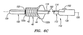
図6A−6Cを参照すると、他の実施の形態の装置110が示されており、装置110は、基端114、末端116及びそれらの間に伸びて長軸120を形成する複数のルーメン(明瞭に図示せず)を含むカテーテル112を含む。他の実施の形態と同様に、1対のバルーン122、例えば末端バルーン122aと該末端バルーン122aに重なり合うか又はそれに隣接する基端バルーン122bを末端に設けてもよい。カテーテル112は、1つ以上のルーメン(図示せず)を含み、例えば、各バルーン122に対する器具ルーメン及び膨張ルーメンを含む。他の実施の形態と同様に、例えば、バルーン122を囲むように、又はバルーン122に乗るように、ステント40又は他の人工器官を末端116に設けてもよい。
Referring to FIGS. 6A-6C, another embodiment of the
前の実施の形態と異なり、装置110は、少なくとも部分的にステント40を覆うシースを含む。例えば、図6Aに示すように、バルーン122が収縮してステント40が収縮状態にあるとき、図6Aに示すように、シース150は、ステント40の第1の端部又は末端部42と、第2の端部又は基端部44との両方を覆ってもよい。シース150は、装置110の前進中、ステント40とバルーン122の一方又は両方を保護するとともに、装置100の丸みのある又は実質的に組織を傷つけることのない先端部となり、そのために末端116は患者の血管中を容易に前進することができる。
Unlike the previous embodiment, the
図示するように、シース150は、ステント40を覆う末端152と、ステント40の先端に配置された末端154を備えていてもよい。末端154は、例えば、組織を傷つけることのない先端部を装置10に与えるために、テーパを付け、丸みを付け、又はその他の形状を付けてもよい。ワイヤ、ケーブル、その他の作動要素160を末端154に連結し、カテーテル112を介して又はカテーテル112に沿って、基端側に向かって基端114まで伸ばしてもよい。例えば、カテーテル112は、作動要素160を収容するための、別途ルーメン、又は溝又は行路、若しくはそれらの両方(図示せず)を備えていてもよい。カテーテル112には、作動要素160に連結された、スライダ、他の制御部又はアクチュエータ162を含むハンドル130を、基端114に設けてもよい。アクチュエータ162が末端に向けられると、作動要素160がシース150を末端側に向けて押圧し、例えば、ステント40の前部又は一部を露出する。
As shown, the
実施形態では、アクチュエータ162は、基端部(図6Aに示す。)から第1の末端部(図6Bに示す。)に向けられ、その状態で、ステント40の第2の部分を露出したまま、ステント40の第1の部分42が覆われる。この状態で、基端側バルーン122bが図示するように膨張し、ステント40の第2の部分42を径方向外側に向けて広げる。代わりに、ステント40の第2の部分44が自分自身で膨張する場合、シース150が第1の末端位置に向けられると、第2の部分44が自動的に外側に広がる。この実施形態では、基端側バルーン122bが膨張すると第2の部分44が広がって拡大する。
In an embodiment, the
図6Cに示すように、アクチュエータ162も、ステント40の第1の部分42がシース150から露出する第2の位置に向けられる。一旦露出すると、末端バルーン122aが膨張してステント40の第1の部分42を膨張する。代わりに、シース150が第2の末端位置に向けられたときに第1の部分42が少なくとも部分的に膨張するように、ステント40の第1の部分42もまた自分自身で膨らむようにしてもよい。その後、末端バルーン122aが膨張して、ステント40の第1の部分42を更に膨張するか又は成形する。
As shown in FIG. 6C, the
代わりに、図示しないが、シース150は、ステント40の第1の部分42だけを覆うようにしてもよい。カテーテル112の上で、基端114から末端116まで伸びるとともにステント40の少なくとも第2の部分44上に延在する、適宜シース、カテーテル、又は管状部材(図示せず)を追加的に設けてもよい。必要であれば、この管状部材は、シース150の基端152に一致させて、円滑な所望の移行部を得るようにしてもよい。他の実施形態では、一つ又はそれ以上の他の制限部材、例えば、ステント40の少なくとも一部を包む一つ又は複数のフィラメント又は他のバインダ(拘束部材)、をステント40上に設けてもよい。このような制限部材は、例えば、アクチュエータを基端側に向けて拘束部材をステント40の回りから引き離す等によって、ハンドル130から取り除くことができる。
Alternatively, although not shown, the
図6Aを参照すると、使用にあたって、上述の実施形態と同様に、装置110にはまず収縮したバルーン122と収縮したバルーン122上に配置されたステント40が提供される。シース150は第1の部分42上に延在している。シース150は、図6Aに示すように、ステント40の第2の部分上に延在していてもよい。この状態で、装置110は、図5Bと同様に、患者の体内に導入されて本体ルーメン92に前進される。始めからシース150がステントの第2の部分42を覆っている場合、図6Bに示すように、シース150を末端に向けて第2の部分42を露出させてもよい。代わりに、別の管状部材が第2の部分44を覆っている場合、管状部材を基端側に引っ込めて第2の部分44を露出させてもよい。
Referring to FIG. 6A, in use,
露出すると、図6Bに示すように、図5Cを参照して説明した手順と同様に、基端側バルーン122bがステント40の第2の部分を広げて膨張する。図5Dと同様に、装置110を前進させて、シース150とそれに覆われたステント40の第1の部分42を小孔90に装入するとともに病変96を介して少なくともその一部をブランチ94に装入する。図6Cに戻ると、シース150は、その後末端に向けられてステント40の第1の部分42を露出させる。その結果、末端バルーン122aが膨張し、例えば、図5Eに示すように病変96を拡張する。ステント40を良好に着座させて第2の部分44を小孔90の輪郭に良好に一致させるために、さらにバルーン122を膨張してもよいし、バルーン122を操作してもよい。ステントが適正に展開すると、バルーン122が縮小し、ステントを残して病変96を拡大したまま、装置110を取り除く。
Upon exposure, the
本明細書で示される要素及び部位は、特定の実施の形態に典型的なものであり、本明細書において開示される他の実施の形態において、又は、それとともに用いられてもよい。さらに、バルーンはステントを膨張させるためのものであるが、例えば、基端及び末端バルーンの1つ又は両方の代わりに、他の膨張部が、本明細書において説明される装置に備えられてもよい。例えば、1組の(又はより多くの)機械的な膨張部は、カテーテルの基端から操作されるカテーテルの末端に備えられてもよい。膨張可能なフレームを覆う皮膚又は他の素材が備えられてもよく、それによって、例えば本明細書において説明される基端及び末端バルーンと同様に、所望の形態に膨張させることができる。 The elements and sites shown herein are typical for a particular embodiment and may be used in or with other embodiments disclosed herein. Further, the balloon is for inflating the stent, but other inflatables may be included in the devices described herein, for example, instead of one or both of the proximal and distal balloons. Good. For example, a set (or more) of mechanical inflations may be provided at the distal end of the catheter that is manipulated from the proximal end of the catheter. Skin or other material covering the inflatable frame may be provided so that it can be inflated to the desired form, for example, similar to the proximal and distal balloons described herein.
発明は種々の修正及び他の形態の影響を受ける一方で、特別な例を図面に示し、また本明細書で詳細に説明する。しかし、開示された特別な形態又は方法に限定されるものではなく、本発明は、添付の特許請求の範囲の範囲内である全ての改良されたもの、均等なもの及び代わりのものを含む。 While the invention is susceptible to various modifications and other forms, specific examples are shown in the drawings and are herein described in detail. However, it is not intended to be limited to the particular forms or methods disclosed, but the invention includes all modifications, equivalents and alternatives that are within the scope of the appended claims.
Claims (17)
基端と、体腔に導入するための大きさの末端と、該基端と末端との間を伸び、それによって長軸を形成する第1及び第2のルーメンとを構成する伸長部と、
前記伸長部の末端に取り付けられた基端と末端、及び該基端と末端との間の中間部とを有し、前記第1のルーメンと連通する内部を有する第1膨張可能部であって、該第1膨張可能部が膨張した際に前記中間部が実質的に均一な断面を有する第1膨張可能部と、
前記伸長部の末端にある、前記第2のルーメンと連通する内部を有する第2膨張可能部であって、前記第1膨張可能部の基端よりも基端側で前記伸長部の末端に取り付けられた基端と、該基端近傍の基端部位と、前記第1膨張可能部の末端の近傍となるよう該第1膨張可能部の中間部の上に延びる末端とを有する第2膨張可能部と、
前記第2膨張可能部の末端と前記第1膨張可能部の中間部とを囲む第1の部位と、前記中間部から基端側に延びる前記第2膨張可能部の基端部位の末端表面を囲む第2の部位とを有する人工器官であって、前記第1の部位が第1の長さを有し、前記第2の部位が第2の長さを有し、該第2の長さが前記第1の長さよりも短く、前記第1の部位が膨張する際に第2の部位よりも大きな力を必要とする材料からなる人工器官とを備え、
前記第2膨張可能部は、前記第1の部位が収縮状態のままで前記第2の部位を拡張状態にまで膨張させるために、前記第1膨張可能部と独立に膨張可能であり、前記第2膨張可能部の基端部位の末端表面が半径方向外方に向けて前記第1膨張可能部の中間部より基端側に膨張するよう、前記第2膨張可能部は膨張した状態で予め定められた大きさまで膨張する弾力性のない材料から形成され、前記人工器官は、前記第2の部位が半径方向外方に向けて前記第1の部位より基端側にフレア状態に拡張するよう、前記第2膨張可能部の基端部位の末端表面を覆い、その後前記第1膨張可能部は、前記第1の部位を拡張状態の第2の部位より小さい拡張状態にまで膨張させるよう膨張可能である装置。 In a device for placing a prosthesis in a small hole in a body cavity,
An extension defining a proximal end, a distal end sized for introduction into a body cavity, and first and second lumens extending between the proximal end and the distal end thereby forming a major axis;
A first inflatable portion having a proximal end and a distal end attached to the distal end of the extension, and an intermediate portion between the proximal end and the distal end and having an interior in communication with the first lumen; A first inflatable portion having a substantially uniform cross section when the first inflatable portion is inflated;
A second inflatable portion having an interior in communication with the second lumen at a distal end of the elongated portion, and attached to a distal end of the elongated portion on a proximal side relative to a proximal end of the first inflatable portion A second inflatable having a proximal end, a proximal portion proximate to the proximal end, and a distal end extending over an intermediate portion of the first inflatable portion to be proximate to the distal end of the first inflatable portion And
Said first and sites surrounding the second inflatable portion end and the middle portion of the first expandable portion end of the distal surface of the second inflatable portion of the proximal end portion extending proximally from the intermediate portion And a second part surrounding the first part, wherein the first part has a first length, the second part has a second length, and the second length A prosthesis made of a material shorter than the first length and made of a material that requires a larger force than the second part when the first part expands,
The second inflatable part is inflatable independently of the first inflatable part in order to inflate the second part to an expanded state while the first part remains in a contracted state, 2. The second inflatable part is predetermined in an expanded state so that the distal surface of the base end part of the inflatable part expands radially outward from the intermediate part of the first inflatable part to the base end side. The prosthesis is formed from a non-elastic material that expands to a predetermined size , and the prosthesis expands in a flared state proximally from the first part toward the radially outward direction. Covering the distal surface of the proximal end portion of the second expandable portion, the first expandable portion is then expandable to expand the first portion to an expanded state that is less than the expanded second portion. A device.
前記第1の部位の上に横たわり、前記第1の部位を覆う第1の位置と前記第1の部位を覆わない第2の位置との間を移動可能な管状部を有する請求項2に記載の装置。 The restraining portion is
The tubular part lying on the first part and movable between a first position covering the first part and a second position not covering the first part is provided. Equipment.
基端と、体腔に導入するための大きさの末端と、該基端と末端との間を伸びる長軸とを有する伸長部と、
前記伸長部の末端に取り付けられる基端及び末端と、先細りの末端部位と、前記基端と先細りの末端部位との間に延びる中間部とを備えた第1膨張部であって、前記中間部が、自身の上で管状の人工器官の第1の部位を受け入れるための長さと、膨張した際に実質的に均一な断面とを有する第1膨張可能部と、
前記第1膨張可能部の近傍で伸長部の末端にある第2膨張可能部であって、該第2膨張可能部が、前記第1膨張可能部の基端よりも基端側で前記伸長部の末端に取り付けられた基端と、該基端近傍の基端部位と、第2膨張可能部の末端が前記第1膨張可能部の末端の近傍となるよう該第1膨張可能部の中間部と先細りの末端部位との上に延びる末端とを有し、前記第1膨張可能部が収縮状態である間、前記人工器官の第2の部位を拡張状態に膨張させるために、伸長部の基端側からの作用で前記第1膨張可能部と独立に膨張可能である第2膨張可能部とを備え、
小孔内での人工器官の位置付けを容易にするべく該人工器官の第2の部位をフレア状態に膨張させるため、前記第2膨張可能部の基端部位が半径方向外方で前記中間部から基端側に膨張する末端表面を形成するよう、前記第2膨張可能部は膨張した状態で予め定められた大きさまで膨張する弾力性のない材料から形成され、
前記第1膨張可能部がその後、前記人工器官の第1の部位を前記第2の部位の膨張状態よりも小さい膨張状態まで膨張させるよう膨張可能である装置。 In a device for placing a prosthesis in a small hole in a body cavity,
An extension having a proximal end, a distal end sized for introduction into a body cavity, and a long axis extending between the proximal end and the distal end;
A first inflatable part comprising a proximal end and a distal end attached to the distal end of the extension, a tapered distal end portion, and an intermediate portion extending between the proximal end and the tapered distal end portion, wherein the intermediate portion A first inflatable portion having a length for receiving a first portion of the tubular prosthesis on itself and a substantially uniform cross-section when inflated;
A second inflatable part at a distal end of the extension part in the vicinity of the first inflatable part, wherein the second inflatable part is closer to the proximal end than the proximal end of the first inflatable part. A proximal end attached to the distal end of the first end, a proximal end portion in the vicinity of the proximal end, and an intermediate portion of the first inflatable portion such that the distal end of the second inflatable portion is in the vicinity of the distal end of the first inflatable portion. And a distal end extending above the tapered end portion, and an extension base for inflating the second portion of the prosthesis to the expanded state while the first inflatable portion is in the contracted state. A second inflatable part that is inflatable independently of the first inflatable part by the action from the end side,
In order to expand the second part of the prosthesis in a flared state in order to facilitate positioning of the prosthesis within the small hole, the proximal end part of the second inflatable part is radially outward from the intermediate part. The second inflatable part is formed of a non-elastic material that expands to a predetermined size in an expanded state so as to form a distal surface that expands proximally.
The apparatus wherein the first inflatable portion is then inflatable to inflate the first portion of the prosthesis to an expanded state that is less than the expanded state of the second portion.
基端と、体腔に導入するための大きさの末端と、前記基端と末端との間を伸びる第1と第2のルーメンとを有し、これにより長軸を形成する伸長部と、
前記伸長部の末端に取り付けられる基端及び末端と、該両端の間の中間部とを備えた第1膨張可能部であって、前記第1のルーメンと連通する内部を有し、前記中間部は、前記第1膨張可能部が膨張したときに実質的に均一の断面を有する第1膨張可能部と、
前記伸長部の末端にある第2膨張可能部であって、該第2膨張可能部が、前記第1膨張可能部の基端よりも基端側で前記伸長部の末端に取り付けられた基端と、該基端近傍の基端部位と、第2膨張可能部の末端が前記第1膨張可能部の末端の近傍となるよう該第1膨張可能部の中間部の上に延びる末端とを有する第2膨張可能部とを備え、
前記第2膨張可能部は、該第2膨張可能部の基端部位の末端表面が半径方向外方で前記第1膨張可能部の中間部より基端側に膨張するよう、膨張した状態で予め定められた大きさまで膨張する弾力性のない材料から形成され、
前記第2膨張可能部は、前記第1膨張可能部が収縮状態にある間に、該第2膨張可能部が予め定められた大きさに膨張可能となるよう、前記第2のルーメンと連通する内部を有し、
前記第1膨張可能部がその後、前記中間部を囲む人工器官を体腔内で拡大された状態に膨張させるよう膨張可能である装置。 In a device for placing a prosthesis in a small hole in a body cavity,
An extension having a proximal end, a distal end sized for introduction into a body cavity, and first and second lumens extending between the proximal end and the distal end, thereby forming a major axis;
A first inflatable portion comprising a proximal end and a distal end attached to the distal end of the extension and an intermediate portion between the ends, the first inflatable portion having an interior communicating with the first lumen; A first inflatable portion having a substantially uniform cross-section when the first inflatable portion is inflated;
A second inflatable portion at a distal end of the extension, wherein the second inflatable portion is attached to the distal end of the extension on a proximal side of the proximal end of the first inflatable portion And a proximal end portion in the vicinity of the proximal end and a distal end extending above the middle portion of the first inflatable portion so that the distal end of the second inflatable portion is in the vicinity of the distal end of the first inflatable portion. A second inflatable part,
The second inflatable portion is previously in an expanded state so that the distal surface of the proximal end portion of the second inflatable portion expands radially outward from the intermediate portion of the first inflatable portion. Formed from a non-elastic material that expands to a defined size ,
The second inflatable portion communicates with the second lumen so that the second inflatable portion can be inflated to a predetermined size while the first inflatable portion is in a contracted state. Has an interior,
The device wherein the first inflatable portion is then inflatable to inflate the prosthesis surrounding the intermediate portion into an expanded state in a body cavity.
前記伸長部の末端を分枝血管の小孔近傍の主血管内に導いた後、前記人工器官の第1の部位が収縮状態にある間に、該人工器官の第2の部位を前記第1の部位から半径方向外方にフレア状態に拡大するよう、前記第2膨張可能部を予め定められた大きさに膨張させ、
その後、前記末端を小孔内に導いた後に、前記膨張した第2の部位を前記小孔を囲む主血管の壁に接触させ、前記第1膨張可能部が前記人工器官の第1の部位を分枝血管の壁に接触させるよう該第1膨張可能部を膨張させるよう構成されている、請求項1−7、9のいずれか一に記載の装置。 The apparatus further comprises a fluid source attached to a proximal end of the extension, the fluid source communicating with the interior of the first and second inflatable portions via the first and second lumens; The fluid source is configured to guide the second part of the prosthesis while the first part of the prosthesis is in a contracted state after guiding the end of the extension into the main blood vessel near the small hole of the branching blood vessel. Inflating the second inflatable part to a predetermined size so as to flare outward from the first part in a radial direction,
Then, after guiding the end into the small hole, the expanded second portion is brought into contact with the wall of the main blood vessel surrounding the small hole, and the first expandable portion moves the first portion of the prosthesis. 10. A device according to any one of claims 1-7, 9 configured to inflate the first inflatable part to contact the wall of a branch vessel.
Applications Claiming Priority (3)
| Application Number | Priority Date | Filing Date | Title |
|---|---|---|---|
| US11/136,266 US7862601B2 (en) | 2005-05-23 | 2005-05-23 | Apparatus and methods for delivering a stent into an ostium |
| US11/136,266 | 2005-05-23 | ||
| PCT/US2006/020105 WO2006127824A1 (en) | 2005-05-23 | 2006-05-23 | Apparatus and methods for delivering a stent into an ostium |
Publications (3)
| Publication Number | Publication Date |
|---|---|
| JP2008541872A JP2008541872A (en) | 2008-11-27 |
| JP2008541872A5 JP2008541872A5 (en) | 2009-07-09 |
| JP5227170B2 true JP5227170B2 (en) | 2013-07-03 |
Family
ID=36792800
Family Applications (1)
| Application Number | Title | Priority Date | Filing Date |
|---|---|---|---|
| JP2008513676A Active JP5227170B2 (en) | 2005-05-23 | 2006-05-23 | Device for placing a stent in a small hole |
Country Status (5)
| Country | Link |
|---|---|
| US (2) | US7862601B2 (en) |
| EP (1) | EP1901797B8 (en) |
| JP (1) | JP5227170B2 (en) |
| CA (1) | CA2609176A1 (en) |
| WO (1) | WO2006127824A1 (en) |
Families Citing this family (41)
| Publication number | Priority date | Publication date | Assignee | Title |
|---|---|---|---|---|
| US9034025B2 (en) * | 2005-05-23 | 2015-05-19 | Ostial Corporation | Balloon catheters and methods for use |
| US20070021819A1 (en) * | 2005-05-23 | 2007-01-25 | Jeff Krolik | Apparatus and Methods for Locating an Ostium of a Vessel |
| US10092429B2 (en) * | 2005-08-22 | 2018-10-09 | Incept, Llc | Flared stents and apparatus and methods for delivering them |
| US7766893B2 (en) * | 2005-12-07 | 2010-08-03 | Boston Scientific Scimed, Inc. | Tapered multi-chamber balloon |
| US8518100B2 (en) * | 2005-12-19 | 2013-08-27 | Advanced Cardiovascular Systems, Inc. | Drug eluting stent for the treatment of dialysis graft stenoses |
| US8398695B2 (en) * | 2006-11-03 | 2013-03-19 | Boston Scientific Scimed, Inc. | Side branch stenting system using a main vessel constraining side branch access balloon and side branching stent |
| US8414611B2 (en) * | 2006-11-03 | 2013-04-09 | Boston Scientific Scimed, Inc. | Main vessel constraining side-branch access balloon |
| US20080132988A1 (en) * | 2006-12-01 | 2008-06-05 | Scimed Life Systems, Inc. | Balloon geometry for delivery and deployment of shape memory polymer stent with flares |
| ITMI20062333A1 (en) | 2006-12-05 | 2008-06-06 | Mario Salerno | DEVICE TO ASSIST THE SCLORESANT TREATMENT OF VARICOSE VEINS |
| US9486345B2 (en) * | 2008-01-03 | 2016-11-08 | Covidien Lp | Methods and systems for placement of a stent adjacent an ostium |
| US8353927B2 (en) * | 2009-05-04 | 2013-01-15 | Merit Medical Systems, Inc. | Radial artery compression device |
| EP2282802A1 (en) * | 2008-05-06 | 2011-02-16 | The Cleveland Clinic Foundation | Balloon for a body lumen and method of use |
| US8088103B2 (en) * | 2008-11-03 | 2012-01-03 | Advanced Catheter Therapies, Inc. | Occlusion perfusion catheter |
| US8758423B2 (en) * | 2009-06-18 | 2014-06-24 | Graftcraft I Goteborg Ab | Device and method for treating ruptured aneurysms |
| JP2013523286A (en) * | 2010-04-02 | 2013-06-17 | カペラ, インコーポレイテッド | System and method for delivering a stent to a body lumen |
| AU2011236083A1 (en) * | 2010-10-20 | 2012-05-10 | Maria G. Aboytes | Catheter apparatuses having expandable mesh structures for renal neuromodulation and associated systems and methods |
| US9108024B2 (en) * | 2012-09-28 | 2015-08-18 | Avent, Inc. | Retention component for placement of enteral feeding tubes |
| US9839543B2 (en) | 2013-03-14 | 2017-12-12 | Cook Medical Technologies Llc | Multi-stage balloon catheter |
| US10842969B2 (en) | 2013-10-25 | 2020-11-24 | Mercator Medsystems, Inc. | Systems and methods of treating malacia by local delivery of hydrogel to augment tissue |
| US20160074186A1 (en) * | 2014-09-15 | 2016-03-17 | Covidien Lp | Coupling a body conduit to tissue |
| CN104398329A (en) * | 2014-09-30 | 2015-03-11 | 浦易(上海)生物技术有限公司 | Completely-degradable net-shaped nasolacrimal stent and implantation system thereof |
| US9980840B2 (en) | 2014-12-08 | 2018-05-29 | Cook Medical Technologies Llc | Delivery device with an expandable positioner for positioning a prosthesis |
| US11160956B1 (en) * | 2015-02-06 | 2021-11-02 | David M. Hoganson | Balloon dilator |
| DE102015107038A1 (en) | 2015-05-06 | 2016-11-10 | Bentley Innomed Gmbh | double balloon |
| EP3291726A4 (en) * | 2015-05-07 | 2019-01-02 | Corfigo, Inc. | Non-occlusive circumferential vascular ablation device |
| US10603195B1 (en) * | 2015-05-20 | 2020-03-31 | Paul Sherburne | Radial expansion and contraction features of medical devices |
| DE102015112390A1 (en) * | 2015-07-29 | 2017-02-02 | Bentley Innomed Gmbh | balloon catheter |
| JP6814804B2 (en) * | 2015-11-20 | 2021-01-20 | ボストン サイエンティフィック サイムド,インコーポレイテッドBoston Scientific Scimed,Inc. | How to join a balloon catheter assembly and a balloon to a catheter shaft |
| US10470905B2 (en) | 2016-03-25 | 2019-11-12 | Ostial Corporation | Balloon catheters and methods for use |
| US11207505B2 (en) | 2017-01-06 | 2021-12-28 | Cardiofocus, Inc. | Balloon catheter and fluid management system thereof |
| IT201700055981A1 (en) * | 2017-05-23 | 2018-11-23 | Lorenzo Nicola Di | Device for the treatment of cardiovascular diseases |
| US10321914B2 (en) * | 2017-06-14 | 2019-06-18 | William Joseph Drasler | Positionable perivalvular occlusion device |
| US10350395B2 (en) | 2017-06-23 | 2019-07-16 | Cook Medical Technologies Llc | Introducer for lumen support or dilation |
| US20180369548A1 (en) * | 2017-06-23 | 2018-12-27 | Cook Medical Technologies Llc | Dual balloon for lumen support or dilation |
| WO2020072837A1 (en) | 2018-10-03 | 2020-04-09 | Ostial Corporation | Inflation devices and systems for balloon catheters and methods for use |
| CN113260405A (en) * | 2018-11-08 | 2021-08-13 | 奥斯蒂尔公司 | Dual balloon catheter and method of use |
| WO2021252720A1 (en) * | 2020-06-11 | 2021-12-16 | Edwards Lifesciences Corporation | Inflatable bodies, systems, and methods for expanding implants |
| US11672683B2 (en) * | 2020-10-05 | 2023-06-13 | National Guard Health Affairs | Bifunctional balloon-expandable and self-expandable stent |
| US20230043660A1 (en) * | 2021-08-04 | 2023-02-09 | Boston Scientific Scimed, Inc. | Ostial stent delivery device, system, and method |
| CN114099100B (en) * | 2022-01-26 | 2022-06-03 | 上海微创心脉医疗科技(集团)股份有限公司 | Branch sheath and blood vessel support conveyer |
| CN114984420A (en) * | 2022-06-20 | 2022-09-02 | 柏为(武汉)医疗科技股份有限公司 | Sinus ostial stent expansion device and sinus ostial stent |
Family Cites Families (88)
| Publication number | Priority date | Publication date | Assignee | Title |
|---|---|---|---|---|
| JPS5431825Y2 (en) * | 1975-06-30 | 1979-10-04 | ||
| US4327736A (en) * | 1979-11-20 | 1982-05-04 | Kanji Inoue | Balloon catheter |
| US4921483A (en) * | 1985-12-19 | 1990-05-01 | Leocor, Inc. | Angioplasty catheter |
| US4744366A (en) * | 1986-09-10 | 1988-05-17 | Jang G David | Concentric independently inflatable/deflatable multiple diameter balloon angioplasty catheter systems and method of use |
| US4763654A (en) * | 1986-09-10 | 1988-08-16 | Jang G David | Tandem independently inflatable/deflatable multiple diameter balloon angioplasty catheter systems and method of use |
| US4950227A (en) * | 1988-11-07 | 1990-08-21 | Boston Scientific Corporation | Stent delivery system |
| US5295958A (en) * | 1991-04-04 | 1994-03-22 | Shturman Cardiology Systems, Inc. | Method and apparatus for in vivo heart valve decalcification |
| FR2688401B1 (en) * | 1992-03-12 | 1998-02-27 | Thierry Richard | EXPANDABLE STENT FOR HUMAN OR ANIMAL TUBULAR MEMBER, AND IMPLEMENTATION TOOL. |
| US5540712A (en) * | 1992-05-01 | 1996-07-30 | Nitinol Medical Technologies, Inc. | Stent and method and apparatus for forming and delivering the same |
| US5415635A (en) * | 1992-07-21 | 1995-05-16 | Advanced Cardiovascular Systems, Inc. | Balloon assembly with separately inflatable sections |
| JP3141601B2 (en) * | 1993-01-22 | 2001-03-05 | 株式会社ニッショー | CATHETER FOR TREATMENT OF LOCAL ANEMIA AND TREATMENT DEVICE USING THE SAME |
| SE505436C2 (en) * | 1993-04-27 | 1997-08-25 | Ams Medinvent Sa | prostatic stent |
| US5409495A (en) * | 1993-08-24 | 1995-04-25 | Advanced Cardiovascular Systems, Inc. | Apparatus for uniformly implanting a stent |
| US5545209A (en) * | 1993-09-30 | 1996-08-13 | Texas Petrodet, Inc. | Controlled deployment of a medical device |
| US5607444A (en) * | 1993-12-02 | 1997-03-04 | Advanced Cardiovascular Systems, Inc. | Ostial stent for bifurcations |
| DE4418336A1 (en) * | 1994-05-26 | 1995-11-30 | Angiomed Ag | Stent for widening and holding open receptacles |
| US5609605A (en) * | 1994-08-25 | 1997-03-11 | Ethicon, Inc. | Combination arterial stent |
| US5549551A (en) * | 1994-12-22 | 1996-08-27 | Advanced Cardiovascular Systems, Inc. | Adjustable length balloon catheter |
| US5749851A (en) * | 1995-03-02 | 1998-05-12 | Scimed Life Systems, Inc. | Stent installation method using balloon catheter having stepped compliance curve |
| BE1009278A3 (en) * | 1995-04-12 | 1997-01-07 | Corvita Europ | Guardian self-expandable medical device introduced in cavite body, and medical device with a stake as. |
| DE19526784A1 (en) | 1995-07-21 | 1997-01-23 | Bavaria Med Tech | Double balloon catheter |
| US5868704A (en) * | 1995-09-18 | 1999-02-09 | W. L. Gore & Associates, Inc. | Balloon catheter device |
| US5632762A (en) | 1995-11-09 | 1997-05-27 | Hemodynamics, Inc. | Ostial stent balloon |
| US8728143B2 (en) * | 1996-06-06 | 2014-05-20 | Biosensors International Group, Ltd. | Endoprosthesis deployment system for treating vascular bifurcations |
| US5725535A (en) * | 1996-09-20 | 1998-03-10 | Hegde; Anant V. | Multiple balloon stent delivery catheter and method |
| EP0835673A3 (en) * | 1996-10-10 | 1998-09-23 | Schneider (Usa) Inc. | Catheter for tissue dilatation and drug delivery |
| EP1723931B1 (en) * | 1996-11-04 | 2012-01-04 | Advanced Stent Technologies, Inc. | Extendible stent apparatus and method for deploying the same |
| US6325826B1 (en) * | 1998-01-14 | 2001-12-04 | Advanced Stent Technologies, Inc. | Extendible stent apparatus |
| US5749890A (en) * | 1996-12-03 | 1998-05-12 | Shaknovich; Alexander | Method and system for stent placement in ostial lesions |
| US6096071A (en) * | 1998-03-26 | 2000-08-01 | Yadav; Jay S. | Ostial stent |
| DE69835634T3 (en) | 1997-05-07 | 2010-09-23 | Cordis Corp. | Intravascular stent and insertion system (obstruction of the ostium of a vessel) |
| US6409755B1 (en) * | 1997-05-29 | 2002-06-25 | Scimed Life Systems, Inc. | Balloon expandable stent with a self-expanding portion |
| DE19739086C1 (en) * | 1997-09-06 | 1999-07-15 | Voelker Wolfram Priv Doz Dr Me | Balloon catheter |
| AU2225999A (en) * | 1998-01-16 | 1999-08-02 | Emory University | Catheter and method of ostial stent placement |
| US6651670B2 (en) * | 1998-02-13 | 2003-11-25 | Ventrica, Inc. | Delivering a conduit into a heart wall to place a coronary vessel in communication with a heart chamber and removing tissue from the vessel or heart wall to facilitate such communication |
| US5938697A (en) * | 1998-03-04 | 1999-08-17 | Scimed Life Systems, Inc. | Stent having variable properties |
| US6136011A (en) | 1998-07-14 | 2000-10-24 | Advanced Cardiovascular Systems, Inc. | Stent delivery system and method of use |
| US7655030B2 (en) * | 2003-07-18 | 2010-02-02 | Boston Scientific Scimed, Inc. | Catheter balloon systems and methods |
| EP1152711B1 (en) * | 1999-01-27 | 2005-07-06 | Boston Scientific Limited | Bifurcation stent delivery system |
| DE19945050A1 (en) * | 1999-09-20 | 2001-04-12 | Tecsana Gmbh | Balloon to prepare and facilitate human birth |
| US6854467B2 (en) * | 2000-05-04 | 2005-02-15 | Percardia, Inc. | Methods and devices for delivering a ventricular stent |
| US6821295B1 (en) * | 2000-06-26 | 2004-11-23 | Thoratec Corporation | Flared coronary artery bypass grafts |
| US20020077691A1 (en) * | 2000-12-18 | 2002-06-20 | Advanced Cardiovascular Systems, Inc. | Ostial stent and method for deploying same |
| US6764504B2 (en) * | 2001-01-04 | 2004-07-20 | Scimed Life Systems, Inc. | Combined shaped balloon and stent protector |
| US20020091434A1 (en) * | 2001-01-05 | 2002-07-11 | Chambers Jeffrey W. | Apparatus and method to position a stent |
| US8252034B2 (en) * | 2001-01-05 | 2012-08-28 | Chambers Jeffrey W | Method of positioning a stent using rods |
| DE60232710D1 (en) * | 2001-02-16 | 2009-08-06 | Cordis Corp | METHOD FOR PRODUCING A BALLOON CATHETER STENT APPLICATION SYSTEM WITH FINISHING |
| US7572270B2 (en) * | 2001-02-16 | 2009-08-11 | Cordis Corporation | Balloon catheter stent delivery system with ridges |
| WO2002067653A2 (en) * | 2001-02-26 | 2002-09-06 | Scimed Life Systems, Inc. | Bifurcated stent and delivery system |
| US6663663B2 (en) * | 2001-05-14 | 2003-12-16 | M.I. Tech Co., Ltd. | Stent |
| AUPR748801A0 (en) * | 2001-09-04 | 2001-09-27 | Stentco Llc | A stent |
| US20030083734A1 (en) * | 2001-10-25 | 2003-05-01 | Curative Ag | Stent |
| WO2003039626A2 (en) * | 2001-11-08 | 2003-05-15 | Houser Russell A | Rapid exchange catheter with stent deployment, therapeutic infusion, and lesion sampling features |
| US7137993B2 (en) * | 2001-12-03 | 2006-11-21 | Xtent, Inc. | Apparatus and methods for delivery of multiple distributed stents |
| GB0130745D0 (en) * | 2001-12-21 | 2002-02-06 | Cathnet Science Holding As | Balloon catheter assembly |
| WO2003063729A2 (en) * | 2002-01-28 | 2003-08-07 | Orbus Medical Technologies Inc. | Flared ostial endoprosthesis and delivery system |
| WO2003105695A2 (en) * | 2002-06-13 | 2003-12-24 | Existent, Inc. | Mechanical structures and implants using said structures |
| US6858038B2 (en) * | 2002-06-21 | 2005-02-22 | Richard R. Heuser | Stent system |
| US6761734B2 (en) * | 2002-07-22 | 2004-07-13 | William S. Suhr | Segmented balloon catheter for stenting bifurcation lesions |
| US7300459B2 (en) * | 2002-10-17 | 2007-11-27 | Heuser Richard R | Stent with covering and differential dilation |
| US20040254627A1 (en) * | 2003-04-04 | 2004-12-16 | Thompson Paul J. | Stent with end adapted for flaring |
| US7105015B2 (en) * | 2003-06-17 | 2006-09-12 | Medtronic Vascular, Inc. | Method and system for treating an ostium of a side-branch vessel |
| US20050049680A1 (en) * | 2003-09-03 | 2005-03-03 | Fischell Tim A. | Side branch stent with split proximal end |
| US20050209674A1 (en) * | 2003-09-05 | 2005-09-22 | Kutscher Tuvia D | Balloon assembly (V) |
| US20050055077A1 (en) * | 2003-09-05 | 2005-03-10 | Doron Marco | Very low profile medical device system having an adjustable balloon |
| CA2544416A1 (en) * | 2003-11-03 | 2005-05-12 | B-Balloon Ltd. | Treatment of vascular bifurcations |
| US9078780B2 (en) * | 2003-11-08 | 2015-07-14 | Cook Medical Technologies Llc | Balloon flareable branch vessel prosthesis and method |
| US20050101968A1 (en) * | 2003-11-12 | 2005-05-12 | Dadourian Daniel G. | Ostial locator device and methods for transluminal interventions |
| US7344557B2 (en) * | 2003-11-12 | 2008-03-18 | Advanced Stent Technologies, Inc. | Catheter balloon systems and methods |
| US20050154447A1 (en) * | 2004-01-09 | 2005-07-14 | Medtronic Vascular, Inc. | Ostium stent system |
| US20050177221A1 (en) * | 2004-02-06 | 2005-08-11 | Mustapha Jihad A. | Ostial stent |
| US20070038283A1 (en) * | 2004-02-06 | 2007-02-15 | Mustapha Jihad A | Ostial stent and balloon |
| US7198632B2 (en) * | 2004-03-02 | 2007-04-03 | Boston Scientific Scimed, Inc. | Occlusion balloon catheter with longitudinally expandable balloon |
| US7753951B2 (en) * | 2004-03-04 | 2010-07-13 | Y Med, Inc. | Vessel treatment devices |
| US20050209673A1 (en) * | 2004-03-04 | 2005-09-22 | Y Med Inc. | Bifurcation stent delivery devices |
| US20060041303A1 (en) * | 2004-08-18 | 2006-02-23 | Israel Henry M | Guidewire with stopper |
| US7455688B2 (en) * | 2004-11-12 | 2008-11-25 | Con Interventional Systems, Inc. | Ostial stent |
| US20060135985A1 (en) * | 2004-12-21 | 2006-06-22 | Cox Daniel L | Vulnerable plaque modification methods and apparatuses |
| US20060155356A1 (en) * | 2005-01-13 | 2006-07-13 | Israel Henry M | Balloon catheter |
| EP1848272A2 (en) | 2005-02-08 | 2007-10-31 | B-Balloon Ltd. | Devices and methods for treatment of vascular bifurcations |
| AR054656A1 (en) * | 2005-04-03 | 2007-07-11 | Liliana Rosa Grinfeld | STENT FOR OSTIAL INJURIES AND VASCULAR FORKS |
| BG109111A (en) * | 2005-04-05 | 2007-02-28 | Николай ДИМИТРОВ | Two-balloon catheter device for coronary angioplastics |
| US7402168B2 (en) * | 2005-04-11 | 2008-07-22 | Xtent, Inc. | Custom-length stent delivery system with independently operable expansion elements |
| US10092429B2 (en) * | 2005-08-22 | 2018-10-09 | Incept, Llc | Flared stents and apparatus and methods for delivering them |
| RU2008114945A (en) * | 2005-09-21 | 2009-10-27 | Б-Баллун Лтд. (Il) | Forked cylinder and stent |
| US7670369B2 (en) * | 2005-10-13 | 2010-03-02 | Cook Incorporated | Endoluminal prosthesis |
| US20070208408A1 (en) * | 2006-03-06 | 2007-09-06 | Boston Scientific Scimed, Inc. | Non-foreshortening sheaths and assemblies for use |
| US8257419B2 (en) * | 2006-03-10 | 2012-09-04 | Cordis Corporation | Apparatus for treating a bifurcated region of a conduit |
-
2005
- 2005-05-23 US US11/136,266 patent/US7862601B2/en active Active
-
2006
- 2006-05-23 JP JP2008513676A patent/JP5227170B2/en active Active
- 2006-05-23 EP EP06771081.4A patent/EP1901797B8/en active Active
- 2006-05-23 CA CA002609176A patent/CA2609176A1/en not_active Abandoned
- 2006-05-23 WO PCT/US2006/020105 patent/WO2006127824A1/en active Application Filing
-
2011
- 2011-01-03 US US12/983,860 patent/US20120004717A1/en not_active Abandoned
Also Published As
| Publication number | Publication date |
|---|---|
| US20060265041A1 (en) | 2006-11-23 |
| EP1901797B8 (en) | 2013-08-21 |
| EP1901797A1 (en) | 2008-03-26 |
| CA2609176A1 (en) | 2006-11-30 |
| US7862601B2 (en) | 2011-01-04 |
| WO2006127824A9 (en) | 2007-03-15 |
| US20120004717A1 (en) | 2012-01-05 |
| WO2006127824A1 (en) | 2006-11-30 |
| JP2008541872A (en) | 2008-11-27 |
| EP1901797B1 (en) | 2013-07-03 |
Similar Documents
| Publication | Publication Date | Title |
|---|---|---|
| JP5227170B2 (en) | Device for placing a stent in a small hole | |
| US10980652B2 (en) | Balloon catheters and methods for use | |
| JP5000656B2 (en) | Flare deployable stent and apparatus and method for manufacturing and using the same | |
| JP4989655B2 (en) | Heart valve delivery system with valve catheter | |
| EP1587449B1 (en) | Varying-diameter vascular implant and balloon | |
| US7819841B2 (en) | Vessel isolation device | |
| US20070173918A1 (en) | Apparatus and methods for locating an ostium of a vessel | |
| US11510797B2 (en) | Balloon catheters and methods for use | |
| JP2009513289A (en) | Flared stent and device and method for delivering them | |
| JP2004522502A (en) | Introducer for placing bifurcated prostheses |
Legal Events
| Date | Code | Title | Description |
|---|---|---|---|
| A521 | Request for written amendment filed |
Free format text: JAPANESE INTERMEDIATE CODE: A523 Effective date: 20090521 |
|
| A621 | Written request for application examination |
Free format text: JAPANESE INTERMEDIATE CODE: A621 Effective date: 20090521 |
|
| A977 | Report on retrieval |
Free format text: JAPANESE INTERMEDIATE CODE: A971007 Effective date: 20110714 |
|
| A131 | Notification of reasons for refusal |
Free format text: JAPANESE INTERMEDIATE CODE: A131 Effective date: 20110726 |
|
| A601 | Written request for extension of time |
Free format text: JAPANESE INTERMEDIATE CODE: A601 Effective date: 20111021 |
|
| A602 | Written permission of extension of time |
Free format text: JAPANESE INTERMEDIATE CODE: A602 Effective date: 20111028 |
|
| A601 | Written request for extension of time |
Free format text: JAPANESE INTERMEDIATE CODE: A601 Effective date: 20111124 |
|
| A602 | Written permission of extension of time |
Free format text: JAPANESE INTERMEDIATE CODE: A602 Effective date: 20111201 |
|
| A601 | Written request for extension of time |
Free format text: JAPANESE INTERMEDIATE CODE: A601 Effective date: 20111222 |
|
| A602 | Written permission of extension of time |
Free format text: JAPANESE INTERMEDIATE CODE: A602 Effective date: 20120105 |
|
| A521 | Request for written amendment filed |
Free format text: JAPANESE INTERMEDIATE CODE: A523 Effective date: 20120125 |
|
| A131 | Notification of reasons for refusal |
Free format text: JAPANESE INTERMEDIATE CODE: A131 Effective date: 20120717 |
|
| A601 | Written request for extension of time |
Free format text: JAPANESE INTERMEDIATE CODE: A601 Effective date: 20121012 |
|
| A602 | Written permission of extension of time |
Free format text: JAPANESE INTERMEDIATE CODE: A602 Effective date: 20121019 |
|
| A521 | Request for written amendment filed |
Free format text: JAPANESE INTERMEDIATE CODE: A523 Effective date: 20121113 |
|
| TRDD | Decision of grant or rejection written | ||
| A01 | Written decision to grant a patent or to grant a registration (utility model) |
Free format text: JAPANESE INTERMEDIATE CODE: A01 Effective date: 20130226 |
|
| A61 | First payment of annual fees (during grant procedure) |
Free format text: JAPANESE INTERMEDIATE CODE: A61 Effective date: 20130315 |
|
| R150 | Certificate of patent or registration of utility model |
Ref document number: 5227170 Country of ref document: JP Free format text: JAPANESE INTERMEDIATE CODE: R150 Free format text: JAPANESE INTERMEDIATE CODE: R150 |
|
| FPAY | Renewal fee payment (event date is renewal date of database) |
Free format text: PAYMENT UNTIL: 20160322 Year of fee payment: 3 |
|
| R250 | Receipt of annual fees |
Free format text: JAPANESE INTERMEDIATE CODE: R250 |
|
| R250 | Receipt of annual fees |
Free format text: JAPANESE INTERMEDIATE CODE: R250 |
|
| R250 | Receipt of annual fees |
Free format text: JAPANESE INTERMEDIATE CODE: R250 |
|
| R250 | Receipt of annual fees |
Free format text: JAPANESE INTERMEDIATE CODE: R250 |
|
| R250 | Receipt of annual fees |
Free format text: JAPANESE INTERMEDIATE CODE: R250 |
|
| R250 | Receipt of annual fees |
Free format text: JAPANESE INTERMEDIATE CODE: R250 |
|
| R250 | Receipt of annual fees |
Free format text: JAPANESE INTERMEDIATE CODE: R250 |
|
| R250 | Receipt of annual fees |
Free format text: JAPANESE INTERMEDIATE CODE: R250 |
|
| R250 | Receipt of annual fees |
Free format text: JAPANESE INTERMEDIATE CODE: R250 |