JP5226012B2 - Dynamic stabilization member by forming connection - Google Patents
Dynamic stabilization member by forming connection Download PDFInfo
- Publication number
- JP5226012B2 JP5226012B2 JP2009547268A JP2009547268A JP5226012B2 JP 5226012 B2 JP5226012 B2 JP 5226012B2 JP 2009547268 A JP2009547268 A JP 2009547268A JP 2009547268 A JP2009547268 A JP 2009547268A JP 5226012 B2 JP5226012 B2 JP 5226012B2
- Authority
- JP
- Japan
- Prior art keywords
- attachment structure
- bone attachment
- medical implant
- implant assembly
- transition
- Prior art date
- Legal status (The legal status is an assumption and is not a legal conclusion. Google has not performed a legal analysis and makes no representation as to the accuracy of the status listed.)
- Expired - Fee Related
Links
- 230000006641 stabilisation Effects 0.000 title description 6
- 238000011105 stabilization Methods 0.000 title description 6
- 210000000988 bone and bone Anatomy 0.000 claims description 132
- 230000007704 transition Effects 0.000 claims description 35
- 239000007943 implant Substances 0.000 claims description 25
- 229920001971 elastomer Polymers 0.000 claims description 14
- 239000000806 elastomer Substances 0.000 claims description 14
- 238000009434 installation Methods 0.000 claims description 8
- 230000006835 compression Effects 0.000 description 33
- 238000007906 compression Methods 0.000 description 33
- 230000033001 locomotion Effects 0.000 description 16
- 125000006850 spacer group Chemical group 0.000 description 13
- 238000005452 bending Methods 0.000 description 12
- 230000036961 partial effect Effects 0.000 description 7
- 230000000712 assembly Effects 0.000 description 6
- 238000000429 assembly Methods 0.000 description 6
- 238000000576 coating method Methods 0.000 description 6
- 229910052751 metal Inorganic materials 0.000 description 6
- 239000002184 metal Substances 0.000 description 6
- 238000000034 method Methods 0.000 description 6
- 239000007787 solid Substances 0.000 description 6
- 238000000465 moulding Methods 0.000 description 5
- 238000003825 pressing Methods 0.000 description 5
- QORWJWZARLRLPR-UHFFFAOYSA-H tricalcium bis(phosphate) Chemical compound [Ca+2].[Ca+2].[Ca+2].[O-]P([O-])([O-])=O.[O-]P([O-])([O-])=O QORWJWZARLRLPR-UHFFFAOYSA-H 0.000 description 5
- 208000027418 Wounds and injury Diseases 0.000 description 4
- 238000002513 implantation Methods 0.000 description 4
- 239000000463 material Substances 0.000 description 4
- 229910000389 calcium phosphate Inorganic materials 0.000 description 3
- 239000001506 calcium phosphate Substances 0.000 description 3
- 235000011010 calcium phosphates Nutrition 0.000 description 3
- 238000001356 surgical procedure Methods 0.000 description 3
- 239000004696 Poly ether ether ketone Substances 0.000 description 2
- 239000004699 Ultra-high molecular weight polyethylene Substances 0.000 description 2
- 238000010521 absorption reaction Methods 0.000 description 2
- 238000013459 approach Methods 0.000 description 2
- 239000011575 calcium Substances 0.000 description 2
- 239000011248 coating agent Substances 0.000 description 2
- 239000002131 composite material Substances 0.000 description 2
- 230000006378 damage Effects 0.000 description 2
- 229910052588 hydroxylapatite Inorganic materials 0.000 description 2
- 238000003780 insertion Methods 0.000 description 2
- 230000037431 insertion Effects 0.000 description 2
- 230000000670 limiting effect Effects 0.000 description 2
- 230000000116 mitigating effect Effects 0.000 description 2
- 239000002991 molded plastic Substances 0.000 description 2
- 229920003052 natural elastomer Polymers 0.000 description 2
- 229920001194 natural rubber Polymers 0.000 description 2
- XYJRXVWERLGGKC-UHFFFAOYSA-D pentacalcium;hydroxide;triphosphate Chemical compound [OH-].[Ca+2].[Ca+2].[Ca+2].[Ca+2].[Ca+2].[O-]P([O-])([O-])=O.[O-]P([O-])([O-])=O.[O-]P([O-])([O-])=O XYJRXVWERLGGKC-UHFFFAOYSA-D 0.000 description 2
- 239000004033 plastic Substances 0.000 description 2
- 229920003023 plastic Polymers 0.000 description 2
- 229920002530 polyetherether ketone Polymers 0.000 description 2
- 229920000642 polymer Polymers 0.000 description 2
- 230000008569 process Effects 0.000 description 2
- 238000012545 processing Methods 0.000 description 2
- 230000002829 reductive effect Effects 0.000 description 2
- 238000000926 separation method Methods 0.000 description 2
- 230000035939 shock Effects 0.000 description 2
- 239000000126 substance Substances 0.000 description 2
- 229920002725 thermoplastic elastomer Polymers 0.000 description 2
- 210000001519 tissue Anatomy 0.000 description 2
- 238000011282 treatment Methods 0.000 description 2
- 229920000785 ultra high molecular weight polyethylene Polymers 0.000 description 2
- 229910014497 Ca10(PO4)6(OH)2 Inorganic materials 0.000 description 1
- 241001631457 Cannula Species 0.000 description 1
- 244000043261 Hevea brasiliensis Species 0.000 description 1
- 239000004698 Polyethylene Substances 0.000 description 1
- 239000002253 acid Substances 0.000 description 1
- 239000000956 alloy Substances 0.000 description 1
- 229910045601 alloy Inorganic materials 0.000 description 1
- 229910052586 apatite Inorganic materials 0.000 description 1
- 230000000975 bioactive effect Effects 0.000 description 1
- 239000003462 bioceramic Substances 0.000 description 1
- 230000036782 biological activation Effects 0.000 description 1
- 239000000316 bone substitute Substances 0.000 description 1
- 238000013329 compounding Methods 0.000 description 1
- 150000001875 compounds Chemical class 0.000 description 1
- 229920001577 copolymer Polymers 0.000 description 1
- 238000005520 cutting process Methods 0.000 description 1
- 230000007547 defect Effects 0.000 description 1
- 230000003412 degenerative effect Effects 0.000 description 1
- 238000013461 design Methods 0.000 description 1
- 238000005553 drilling Methods 0.000 description 1
- 230000002500 effect on skin Effects 0.000 description 1
- 238000005530 etching Methods 0.000 description 1
- 235000019589 hardness Nutrition 0.000 description 1
- XLYOFNOQVPJJNP-UHFFFAOYSA-M hydroxide Chemical compound [OH-] XLYOFNOQVPJJNP-UHFFFAOYSA-M 0.000 description 1
- 230000003100 immobilizing effect Effects 0.000 description 1
- 208000014674 injury Diseases 0.000 description 1
- 229910052500 inorganic mineral Inorganic materials 0.000 description 1
- 150000002500 ions Chemical class 0.000 description 1
- 239000011707 mineral Substances 0.000 description 1
- 239000000203 mixture Substances 0.000 description 1
- 230000035515 penetration Effects 0.000 description 1
- VSIIXMUUUJUKCM-UHFFFAOYSA-D pentacalcium;fluoride;triphosphate Chemical compound [F-].[Ca+2].[Ca+2].[Ca+2].[Ca+2].[Ca+2].[O-]P([O-])([O-])=O.[O-]P([O-])([O-])=O.[O-]P([O-])([O-])=O VSIIXMUUUJUKCM-UHFFFAOYSA-D 0.000 description 1
- 229920001692 polycarbonate urethane Polymers 0.000 description 1
- -1 polyethylene Polymers 0.000 description 1
- 229920000573 polyethylene Polymers 0.000 description 1
- 229920001195 polyisoprene Polymers 0.000 description 1
- 229920002635 polyurethane Polymers 0.000 description 1
- 239000004814 polyurethane Substances 0.000 description 1
- 229920003225 polyurethane elastomer Polymers 0.000 description 1
- 238000002360 preparation method Methods 0.000 description 1
- 230000001681 protective effect Effects 0.000 description 1
- 230000003014 reinforcing effect Effects 0.000 description 1
- 230000000284 resting effect Effects 0.000 description 1
- 230000000717 retained effect Effects 0.000 description 1
- 238000005507 spraying Methods 0.000 description 1
- 230000007480 spreading Effects 0.000 description 1
- 238000003892 spreading Methods 0.000 description 1
- 238000004544 sputter deposition Methods 0.000 description 1
- 229920003051 synthetic elastomer Polymers 0.000 description 1
- 229920001059 synthetic polymer Polymers 0.000 description 1
- GBNXLQPMFAUCOI-UHFFFAOYSA-H tetracalcium;oxygen(2-);diphosphate Chemical compound [O-2].[Ca+2].[Ca+2].[Ca+2].[Ca+2].[O-]P([O-])([O-])=O.[O-]P([O-])([O-])=O GBNXLQPMFAUCOI-UHFFFAOYSA-H 0.000 description 1
- 238000004804 winding Methods 0.000 description 1
Images


Classifications
-
- A—HUMAN NECESSITIES
- A61—MEDICAL OR VETERINARY SCIENCE; HYGIENE
- A61B—DIAGNOSIS; SURGERY; IDENTIFICATION
- A61B17/00—Surgical instruments, devices or methods
- A61B17/56—Surgical instruments or methods for treatment of bones or joints; Devices specially adapted therefor
- A61B17/58—Surgical instruments or methods for treatment of bones or joints; Devices specially adapted therefor for osteosynthesis, e.g. bone plates, screws or setting implements
- A61B17/68—Internal fixation devices, including fasteners and spinal fixators, even if a part thereof projects from the skin
- A61B17/70—Spinal positioners or stabilisers, e.g. stabilisers comprising fluid filler in an implant
- A61B17/7001—Screws or hooks combined with longitudinal elements which do not contact vertebrae
- A61B17/7002—Longitudinal elements, e.g. rods
- A61B17/7019—Longitudinal elements having flexible parts, or parts connected together, such that after implantation the elements can move relative to each other
- A61B17/7031—Longitudinal elements having flexible parts, or parts connected together, such that after implantation the elements can move relative to each other made wholly or partly of flexible material
-
- A—HUMAN NECESSITIES
- A61—MEDICAL OR VETERINARY SCIENCE; HYGIENE
- A61B—DIAGNOSIS; SURGERY; IDENTIFICATION
- A61B17/00—Surgical instruments, devices or methods
- A61B17/56—Surgical instruments or methods for treatment of bones or joints; Devices specially adapted therefor
- A61B17/58—Surgical instruments or methods for treatment of bones or joints; Devices specially adapted therefor for osteosynthesis, e.g. bone plates, screws or setting implements
- A61B17/68—Internal fixation devices, including fasteners and spinal fixators, even if a part thereof projects from the skin
- A61B17/70—Spinal positioners or stabilisers, e.g. stabilisers comprising fluid filler in an implant
- A61B17/7001—Screws or hooks combined with longitudinal elements which do not contact vertebrae
- A61B17/7002—Longitudinal elements, e.g. rods
- A61B17/701—Longitudinal elements with a non-circular, e.g. rectangular, cross-section
-
- A—HUMAN NECESSITIES
- A61—MEDICAL OR VETERINARY SCIENCE; HYGIENE
- A61B—DIAGNOSIS; SURGERY; IDENTIFICATION
- A61B17/00—Surgical instruments, devices or methods
- A61B17/56—Surgical instruments or methods for treatment of bones or joints; Devices specially adapted therefor
- A61B17/58—Surgical instruments or methods for treatment of bones or joints; Devices specially adapted therefor for osteosynthesis, e.g. bone plates, screws or setting implements
- A61B17/68—Internal fixation devices, including fasteners and spinal fixators, even if a part thereof projects from the skin
- A61B17/70—Spinal positioners or stabilisers, e.g. stabilisers comprising fluid filler in an implant
- A61B17/7001—Screws or hooks combined with longitudinal elements which do not contact vertebrae
- A61B17/7032—Screws or hooks with U-shaped head or back through which longitudinal rods pass
-
- A—HUMAN NECESSITIES
- A61—MEDICAL OR VETERINARY SCIENCE; HYGIENE
- A61B—DIAGNOSIS; SURGERY; IDENTIFICATION
- A61B17/00—Surgical instruments, devices or methods
- A61B17/56—Surgical instruments or methods for treatment of bones or joints; Devices specially adapted therefor
- A61B17/58—Surgical instruments or methods for treatment of bones or joints; Devices specially adapted therefor for osteosynthesis, e.g. bone plates, screws or setting implements
- A61B17/68—Internal fixation devices, including fasteners and spinal fixators, even if a part thereof projects from the skin
- A61B17/70—Spinal positioners or stabilisers, e.g. stabilisers comprising fluid filler in an implant
- A61B17/7001—Screws or hooks combined with longitudinal elements which do not contact vertebrae
- A61B17/7035—Screws or hooks, wherein a rod-clamping part and a bone-anchoring part can pivot relative to each other
- A61B17/7037—Screws or hooks, wherein a rod-clamping part and a bone-anchoring part can pivot relative to each other wherein pivoting is blocked when the rod is clamped
-
- A—HUMAN NECESSITIES
- A61—MEDICAL OR VETERINARY SCIENCE; HYGIENE
- A61B—DIAGNOSIS; SURGERY; IDENTIFICATION
- A61B17/00—Surgical instruments, devices or methods
- A61B17/56—Surgical instruments or methods for treatment of bones or joints; Devices specially adapted therefor
- A61B17/58—Surgical instruments or methods for treatment of bones or joints; Devices specially adapted therefor for osteosynthesis, e.g. bone plates, screws or setting implements
- A61B17/68—Internal fixation devices, including fasteners and spinal fixators, even if a part thereof projects from the skin
- A61B17/70—Spinal positioners or stabilisers, e.g. stabilisers comprising fluid filler in an implant
- A61B17/7001—Screws or hooks combined with longitudinal elements which do not contact vertebrae
- A61B17/7002—Longitudinal elements, e.g. rods
- A61B17/7004—Longitudinal elements, e.g. rods with a cross-section which varies along its length
- A61B17/7008—Longitudinal elements, e.g. rods with a cross-section which varies along its length with parts of, or attached to, the longitudinal elements, bearing against an outside of the screw or hook heads, e.g. nuts on threaded rods
-
- A—HUMAN NECESSITIES
- A61—MEDICAL OR VETERINARY SCIENCE; HYGIENE
- A61B—DIAGNOSIS; SURGERY; IDENTIFICATION
- A61B17/00—Surgical instruments, devices or methods
- A61B17/56—Surgical instruments or methods for treatment of bones or joints; Devices specially adapted therefor
- A61B17/58—Surgical instruments or methods for treatment of bones or joints; Devices specially adapted therefor for osteosynthesis, e.g. bone plates, screws or setting implements
- A61B17/68—Internal fixation devices, including fasteners and spinal fixators, even if a part thereof projects from the skin
- A61B17/70—Spinal positioners or stabilisers, e.g. stabilisers comprising fluid filler in an implant
- A61B17/7049—Connectors, not bearing on the vertebrae, for linking longitudinal elements together
- A61B17/705—Connectors, not bearing on the vertebrae, for linking longitudinal elements together for linking adjacent ends of longitudinal elements
Landscapes
- Health & Medical Sciences (AREA)
- Orthopedic Medicine & Surgery (AREA)
- Life Sciences & Earth Sciences (AREA)
- Neurology (AREA)
- Surgery (AREA)
- Heart & Thoracic Surgery (AREA)
- Engineering & Computer Science (AREA)
- Biomedical Technology (AREA)
- Nuclear Medicine, Radiotherapy & Molecular Imaging (AREA)
- Medical Informatics (AREA)
- Molecular Biology (AREA)
- Animal Behavior & Ethology (AREA)
- General Health & Medical Sciences (AREA)
- Public Health (AREA)
- Veterinary Medicine (AREA)
- Surgical Instruments (AREA)
- Prostheses (AREA)
Description
本発明は、骨外科、特に脊椎外科に使用される動的固定アセンブリに関し、特に、そのアセンブリのための、少なくとも2つの骨留め具に取り付けられる縦長接続部材に関する。 The present invention relates to a dynamic fixation assembly for use in bone surgery, particularly spinal surgery, and more particularly to an elongate connection member attached to at least two bone fasteners for the assembly.
歴史的には、固定関係に置かれている隣接椎骨に沿って、骨用ねじ又は他の骨留め具と、協働する縦長接続部材又は他の棒状部材を配設することにより、その隣接椎骨を連合するということは普通に行われてきたことである。その連合により、1つ以上の椎骨間接続が永続的に固定されることとなった。骨用ねじ、フック、他の種類の留め具を椎骨に直接的に留めることにより、椎骨にかなりの力がかかることになり、そのような力により究極的には椎骨に付いた骨用ねじや他の留め金を緩めてしまう結果となっていたので、上記連合により、たとえそのようなインプラントが究極的に壊れたり外れてしまったりしても、脊椎を所望の位置に維持することができる縦長接続部材が骨の代用品として発達発展してきた。その連合というのはずっと脊椎安定化処置のうちの所望の一構成であったので、縦長接続部材というのは、屈曲、伸長、捻じれ、伸延、及び圧縮に対して多大な耐性を有するような材料、大きさ及び形で設計されてきており、それにより実質的に連合されるべき脊椎の一部を固定化するものであった。従って、縦長接続部材というのは、とりわけその長さ方向の全体に渡って均質であり、通常、一定サイズの直径又は幅を有する単一部材又は合成部材から作られ、実質的に硬質な支持体であった。 Historically, adjacent bones or other bone fasteners and cooperating longitudinal connecting members or other rods along the adjacent vertebrae that are placed in a fixed relationship can be placed in the adjacent vertebrae. It is a common practice to tie up. The association resulted in permanent fixation of one or more intervertebral connections. Fastening bone screws, hooks, and other types of fasteners directly to the vertebrae can cause considerable force on the vertebrae, which ultimately leads to bone screws and Due to the result of loosening the other clasps, the above-mentioned association allows the spine to remain in the desired position even if such implants ultimately break or fall off Connecting members have been developed and developed as bone substitutes. Since the association has always been a desired configuration of spinal stabilization procedures, the longitudinal connection member is such that it has great resistance to bending, stretching, twisting, distraction, and compression. It has been designed with material, size and shape, thereby immobilizing a portion of the spine to be substantially associated. Longitudinal connecting members are therefore homogeneous, in particular over their entire length, usually made of a single or composite member having a constant size diameter or width, and a substantially rigid support. Met.
しかしながら、連合は、常に望ましいものではなかった。連合や更に硬い縦長接続部材又は他の硬い構造を使用することの代わりとして、“柔らかい”又は“動的な”安定化へのアプローチというのがあり、そこでは、椎骨間の曲げ、伸び、伸延、圧縮、横曲げ、及び捻じれに対して、できる限り通常の付加パターンを創り出すという試みの下で、一対の茎状ねじの間を固定する弾性縦長接続部材として、フレキシブルなループ型、S型、C型、又はU型部材、又は、コイル状及び/又はばね状部材が利用されている。この分野で知られている他の柔軟な、又は動的なシステムとしては、フレキシブルカード又は鎖により接続された骨留め具というものがあり、とりわけ合成高分子材料でできているものである。そのようなカード又は鎖は、それらが埋め込まれる際に、隣接骨留め具間に配設される、カニューレを有するスペーサーを通り抜けることができる。それらのスペーサーはとりわけ骨留め具間の空間を補い、カード又は鎖の曲げ方向の動きを制限するので、全体システムを強化支持するものである。そのようなカード又は鎖型のシステムは、特別な骨留め具が必要であると共に骨留め具においてカード又は鎖に対して力を加えて保持するための道具が必要であった。フレキシブルではあるものの、そのようなシステムに利用されるカード又は鎖は、安定した支持システムを提供するために、最大荷重にまで延ばされて引っ張られる必要があるので、一端埋め込まれると、そのようなカード又は鎖によりシステムが弾性的に伸延したり伸びたりすることはなかった。 However, coalition has not always been desirable. An alternative to using an association or even a stiffer longitudinal connection member or other rigid structure is an approach to “soft” or “dynamic” stabilization, where bending, stretching and distraction between vertebrae As an elastic vertically long connecting member that fixes between a pair of stem-like screws under an attempt to create a normal additional pattern as much as possible against compression, lateral bending, and twisting, a flexible loop type, S type C-shaped or U-shaped members, or coil-shaped and / or spring-shaped members are used. Other flexible or dynamic systems known in the art include bone fasteners connected by flexible cards or chains, especially those made of synthetic polymeric materials. Such cards or chains can pass through spacers with cannulas disposed between adjacent bone fasteners when they are implanted. These spacers, among other things, make up the space between the bone fasteners and limit the movement of the card or chain in the bending direction, thus reinforcing the overall system. Such a card or chain type system required a special bone fastener and a tool for applying force and holding against the card or chain in the bone fastener. Although flexible, cards or chains utilized in such systems need to be extended and pulled to maximum load to provide a stable support system, so once embedded, such as The card or chain did not stretch or stretch the system elastically.
故に、脊椎動作に関わるそのような複雑で動的な条件があることから、十分な疲労強度を呈して、連合を伴わずに脊椎の安定で防御された動きを提供し、延設弾性又はフレキシブル接続部材により強化されて支持された脊椎の一部のいくらかの自然な動きを可能とするようなフレキシブル及び/又は弾性的延設縦長接続部材を設計する要求が生じていた。また、脊椎の一部又はある長さ部分が、連合のようなより硬い安定化を必要としている一方、他の部分又は他の長さ部分は、保護された動きを可能とするようなより動的なシステムにより、より良く支持され得るというような状態も要求されている。 Hence, because of such complex and dynamic conditions involved in spinal motion, it exhibits sufficient fatigue strength and provides a stable and protected movement of the spine without association, extended elasticity or flexible There has been a need to design a flexible and / or elastically extending longitudinal connection member that allows some natural movement of the portion of the spine that is reinforced and supported by the connection member. Also, some or some length of the spine may need a stiffer stabilization such as an association, while other or other lengths may be more moving to allow protected movement. There is also a demand for a situation where it can be better supported by a typical system.
少なくとも2つの骨留め具の間に使用される本発明の縦長接続部材アセンブリは、脊椎の動的な保護された動きを提供し、また望まれるのであれば、連合により延設されて、脊椎の隣接する骨に沿って追加の動的部分が形成されるか、又はより硬質な支持が提供される。本発明によれば、エラストマーのような棒状成形可塑性構造体が、成形又は他の固定処理、例えば限定されないが、化学的結合、配合、又は面接着により、延設硬質部に端部に固定される。例えば、本発明の一実施形態においては、成型プラスチックが、硬質ロッドの端部の複数の貫通腔に配設される。本発明の縦長接続部材アセンブリは、一対の骨留め具の間に配置される遷移又は接続部を備えており、その遷移部は、第一の実質的に固い硬質部と、少なくともいくらかの弾性を有した第二の成形部を有している。スリーブ又はスペーサーが、遷移部の第一及び第二部位の結合部を取り囲む。スリーブは、一対の骨留め具の間であって、それらに接触して延設される。遷移部及び外側スリーブは、動的に協働し、それらはいくらかのフレキシビリティを有し、外側スリーブが主に内側遷移部の屈曲動作を制限して保護する。外側スリーブは、2つの骨留め具の間への据え付けの際に圧縮される溝部を備えることもできる。 The elongate connection member assembly of the present invention used between at least two bone fasteners provides dynamic, protected movement of the spine and, if desired, is extended by a tie so that the spinal Additional dynamic parts are formed along the adjacent bone or a stiffer support is provided. In accordance with the present invention, a rod-shaped molded plastic structure, such as an elastomer, is fixed at the end to an extended hard section by molding or other fixing processes, such as, but not limited to, chemical bonding, compounding, or surface bonding. The For example, in one embodiment of the present invention, molded plastic is disposed in the plurality of through-cavities at the end of the hard rod. The longitudinal connection member assembly of the present invention includes a transition or connection disposed between a pair of bone fasteners, the transition having at least some elasticity with a first substantially rigid rigid portion. It has a second molded part. A sleeve or spacer surrounds the junction of the first and second portions of the transition. The sleeve extends between and in contact with the pair of bone fasteners. The transition and outer sleeve cooperate dynamically, they have some flexibility, and the outer sleeve mainly limits and protects the bending motion of the inner transition. The outer sleeve can also include a groove that is compressed during installation between the two bone fasteners.
本発明の実施形態は、例えば、端部の近くに複数の開口を有した金属ロッドのような、実質的に固い硬質第一部を含んでいる。第二の固体弾性ロッド部は成形処理により加工されるが、その加工においては、弾性ロッド部を形成する可塑性重合体が、金属ロッドの開口に流れ込み、それにより第一及び第二部位が互いに固定されるように、弾性ロッド部が金属ロッド部に近接して形成される。 Embodiments of the present invention include a substantially rigid hard first portion, such as, for example, a metal rod having a plurality of openings near the ends. The second solid elastic rod part is processed by a molding process, in which the plastic polymer forming the elastic rod part flows into the opening of the metal rod, thereby fixing the first and second parts together. As described above, the elastic rod portion is formed close to the metal rod portion.
本発明には各種の実施形態が可能である。例えば、本発明の実施形態によれば、円筒形ロッド、正方形又は矩形断面の板、又は異なる硬度を有した他の実質的硬質構造が、いろいろな剛性や弾性を有するフレキシブルロッド又は板と接続可能である。硬質部又はフレキシブル部のどちらも、1つ又は複数の骨留め具に取り付けるために、より長くしてもよいし、より短くしてもよい。 Various embodiments are possible for the present invention. For example, according to embodiments of the present invention, cylindrical rods, square or rectangular cross-section plates, or other substantially rigid structures with different hardnesses can be connected to flexible rods or plates of varying stiffness and elasticity. It is. Either the hard part or the flexible part may be longer or shorter for attachment to one or more bone fasteners.
故に、硬質な部分又は長さ部分と、よりフレキシブルな部分又は長さ部分の双方を有した縦長接続部材を備えた動的医療インプラント安定化アセンブリであって、そのフレキシブルな部分は、アセンブリの曲げ、捻じれ、圧縮、及び伸延の少なくとも1つを許容するような動的医療インプラント安定化アセンブリを提供することが本発明の1つの目的である。本発明の他の目的は、フレキシブルな部分が外側保護スリーブに挿入可能であるようなアセンブリを提供することにある。本発明の更なる目的は、外側スリーブが、据え付けに際して圧縮され得るようなアセンブリを提供することにある。本発明の更なる目的は、骨用ねじ、フック、他の骨留め具のような各種部材と共に利用される動的医療インプラント縦長接続部材を提供することにある。本発明の他の目的は、1つ以上のよりフレキシブルな部分又は箇所に一体的に連結される固い桿状部分のような、より硬質な又は固い接続部材部分又は箇所を、要求に応じて提供することにある。更に、本発明の目的は、少なくとも2つの骨留め具とその間の縦長接続部材とを備える軽量で、小型で、複雑でないアセンブリを提供することにある。更にまた、本発明の目的は、使用が容易で、特に意図した使用に適した装置及び方法を提供することにあり、その装置は、比較的安価で、使用に適しているものである。 Thus, a dynamic medical implant stabilization assembly comprising a longitudinal connection member having both a rigid portion or length portion and a more flexible portion or length portion, the flexible portion being a bending portion of the assembly. It is an object of the present invention to provide a dynamic medical implant stabilization assembly that allows at least one of twisting, compression, and distraction. It is another object of the present invention to provide an assembly in which the flexible portion can be inserted into the outer protective sleeve. It is a further object of the present invention to provide an assembly in which the outer sleeve can be compressed upon installation. It is a further object of the present invention to provide a dynamic medical implant longitudinal connection member for use with various members such as bone screws, hooks and other bone fasteners. Another object of the present invention is to provide a harder or harder connection member portion or spot on demand, such as a rigid hook-shaped portion that is integrally connected to one or more more flexible portions or places. There is. It is a further object of the present invention to provide a lightweight, compact and uncomplicated assembly comprising at least two bone fasteners and a longitudinal connection member therebetween. It is a further object of the present invention to provide an apparatus and method that is easy to use and particularly suitable for the intended use, which is relatively inexpensive and suitable for use.
本発明の他の目的及び利点は、添付図面と共に考慮されるべき以下の詳細な説明から明らかになるであろう。詳細な説明には例証及び例示で説明される実施の形態が記載されている。 Other objects and advantages of the present invention will become apparent from the following detailed description, which should be considered in conjunction with the accompanying drawings. The detailed description includes embodiments described by way of illustration and example.
図面は、この明細書の一部を構成し、本発明の実施の形態を含み、その各種目的や特徴を図示するものである。 The drawings constitute a part of this specification, include embodiments of the present invention, and illustrate various objects and features thereof.
要求に応じて、本発明の詳細な実施形態がここに開示される。しかしながら、開示された実施形態は発明の単なる例にすぎず、発明は各種の形態で具現化できるであろう。ゆえに、ここに開示された特定の構造的及び機能的詳細は、限定的に解釈されるべきではなく、単に請求の範囲の基礎として、また当業者が、実質的に適切に具体化された構造に本発明を多様的に採用できるように教示するための代表的な基礎として解釈されるべきである。また、この明細書において、頂、底、上方及び下方等の語句は、多様な図面に対する整合のため使用されると共にそのような機器に通常適用される内包を意味しており、実際に使用される応用及び協働骨留め具における接続部材アセンブリの位置づけを制限するようなものではない。 As required, detailed embodiments of the present invention are disclosed herein. However, the disclosed embodiments are merely examples of the invention, and the invention may be embodied in various forms. Accordingly, the specific structural and functional details disclosed herein are not to be construed as limiting, but merely as a basis for the claims and by those skilled in the art which are substantially appropriately embodied. It should be construed as a representative basis for teaching the present invention so that it can be used in various ways. Further, in this specification, terms such as top, bottom, upper and lower are used for alignment with various drawings and mean inclusions usually applied to such devices, and are actually used. It is not intended to limit the positioning of the connecting member assembly in the application and the collaborative bone fastener.
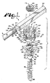
図1−8を参照すると、参照番号1は、概して、本発明の動的安定化縦長接続部材アセンブリを示している。接続部材アセンブリ1は、棒状であり、中心軸Aを有し、また概して、第一硬質部材6と、第二のよりフレキシブルなエラストマー(ゴム弾性)部材7と、部材6及び7の結合部及びその近くに配設される中央動的接続又は遷移部又は部分8と、を含んでいる。遷移部又は部分8は、スペーサー又はスリーブ10に受容されるものであり、図8に示すように、アセンブリ1が、少なくとも一対の骨用ねじアセンブリ15と共に動作可能に組み付けられる際に、そのスリーブ10は、最終的に部分8について正しく位置付けされる。本発明の縦長接続部材アセンブリ1と共に使用され得る骨用ねじアセンブリ、一般的に15は、図1に例示されている。
Referring to FIGS. 1-8,
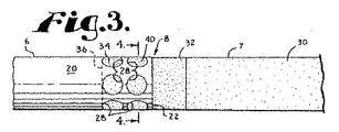
硬質部材6は、典型的には、外側円筒面20を有する図示の固体の桿(ロッド)のように、実質的に固体構造をしている。硬質部材6は、更に、中空となっており、及び/又は複数の貫通腔又は開口を有する端部22を備えている。図示の実施形態においては、端部22に近いロッド部24は、実質的に管状であり、内側円筒面26と、外側面20及び内側面26の双方に通じて開口する複数の貫通開口又は貫通腔28とを有している。
The
図示の実施形態におけるエラストマー部材7は、実質的に板形状であり、実質的に正方形の断面を有する延設部30と、テーパー部32と、硬質部材接続部34とを有している。接続部34は、部材7の端部36近傍に配設されている。図4に示されるように、延設部30は、円筒部材6の直径と実質的に同じ断面幅を有しており、テーパー部32は、部材7の延設部30の板形状から部材6の部位24の円筒形状へ、形が僅かに徐々に変化する部分である。部位30,32及び34は、一体であり、好ましくは、硬質部材6の存在の下で、かつその近傍において、部材7を成形することにより加工されるので、部位34は、部位30及び32の成形と共に、内側円筒面26で画定される空洞に入り込み、更にその部位34は、硬質部材6の開口28の各々にも流れ込む。ある実施形態においては、部位34は、硬質部材6とは分離して加工され、そのとき部位34のフレキシブルな突起40は、エラストマー部材7の端部36が硬質部材6の端部22に挿入される際に、硬質部材6の開口28内に受容されるような大きさ及び形状(例えば、分離成形又は加工により)を有するようにしてもよいことが予見できるであろう。
The
部材6及び7の各々は、図9−11に示すような円筒形状を有していてもよいことが予見できるであろう。また、部材6及び7の1つ又は双方が、限定されることはないが例えば楕円、正方形及び長方形、又は他の曲線もしくは多角形の形状等の断面を有するような他の形状をしていてもよい。また、部材6及び7は、同じ断面を有していてもよいし、異なる断面を有していてもよい。部材6及び7は、それぞれ、骨用ねじ15、後述される他の骨用ねじ、又はフックのような、少なくとも1つから複数までの骨取付け部材と協働する棒材である。硬質部材6は、金属、合金、又は、ポリエーテルエーテルケトン(PEEK)、超高分子量ポリエチレン(UHMWP)、ポリウレタン、及び複合体のような可塑性重合体もその1つである他の適した材料で作られる。エラストマー部材7は、天然又は合成エラストマーから成り、それらとしてはポリイソプレン(天然ゴム)、合成重合体、共重合体、及び、熱可塑性エラストマー、並びにそれらの混合物があるが、これらに限定されることはない。なお、図示された部材7は、ポリウレタンエラストマーである。図示のスリーブ10も、好ましくは、部材7のエラストマーよりも高い剛性を有する、例えばポリエチレン又はポリカーボネートウレタンである熱可塑性エラストマーのようなプラスチックからできている。摩耗デブリが少ないか又は全くないようにするために、スリーブ10の内側面、及び/又は、部材6及び7の協働部の外側面は、イオン結合技法及び/又は他の気体又は化学的処理等により、ごく薄く、ごく固く、ごくすべすべに、ごく滑らかに、被膜され得る。遷移部8及び部位30に沿った屈曲又は曲げ性に関し、相対的に更に硬質なアセンブリ1又は相対的に更にフレキシブルなアセンブリ1を提供するように、部材7は大きさと形と材料が決められるということが予見できるであろう。更に、部位30が延設されるとき、スリーブ10が好ましくはそのような棒材に沿って骨用ねじ間に配設される。また、骨用ねじ間の距離は可変であるので、部材7は、その剛性を高めたり低めたりする必要性を有していてもよい。
It can be foreseen that each of the
図5−8を特に参照して、スリーブ又はスペーサー10は、アセンブリ1の中央部分又は遷移部8と有効に協働する、アセンブリ1の一部材であって、箇所8の動きを制限したり保護したりしている。スリーブ10は、また、それがなければ硬質部材6とエラストマー部材7の接合部近傍で起こり得る損傷から患者の体の組織を守っている。それで、スリーブ10は、後に詳述するように、骨用ねじ15の各協働平坦側面の間で均一で正確に配置され、スリーブ10の平坦端面46及び48とその各協働平坦側面とがしっかりと接触するような大きさと形状を有している。更に、後に詳述するのであるが、本発明のいくつかの実施形態においては、スリーブ10が埋め込まれ、骨用ねじアセンブリ15が、縦長接続部材アセンブリ1に対して、固定位置に締め付けられるとき、アセンブリ1及び/又は骨用ねじ15を埋め込むのに利用される道具が操作され、隣接骨用ねじ15の向い合う面の間で、スリーブ10が軸方向に圧縮される。据え付け中のそのような圧縮により、埋め込み用道具が骨用ねじ15から外されると、その骨用ねじ15の間に位置する部材7にいくらかの張力及び/又は伸延力がかかり、スリーブ面46及び48は向い合う骨用ねじ面を押圧するのであるが、接続部8は、骨用ねじ15の各々に対して固定している。スリーブ10と中央接続部材8の間のそのような動的張力/圧縮力関係により、アセンブリ全体が更に頑強になって安定になり、また、骨用ねじ15の間に配設された接続部材アセンブリ1の全体が必要であれば脊椎の動きに応じて伸びるようになる。アセンブリの安定性及び強度が増したことにより、例えば、フレキシブルカードとスペーサーを使用したタイプの縦長接続部材アセンブリよりも、小さく、小型で、嵩張らず、構造が複雑でない縦長接続部材アセンブリの有効使用が可能になった。
With particular reference to FIGS. 5-8, the sleeve or
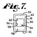
図示のスリーブ10は、相対する側面50と一対の相対する前方/後方側面又は表面52を伴った外側矩形断面を有している。各面50,52は、平坦端面46及び48の間で拡がっている。スリーブ10の形状により、平行面50の間の幅は、面52の間の距離よりも短くなる。そのような形状により、前方/後方曲面52の間に距離があるので、部分8のフレキシブル部材7が曲がらないための十分な堅さや支持が得られる。一方、平坦面50の間の距離はより狭くなっているので、椎骨に当たることなく隣接する椎骨の間にスリーブ10を配置することができる。言い換えれば、中央又は遷移部8にある部材7の曲げ動きについて所望の限界を生み出すのに十分な大きさの直径を有する円筒形スリーブは、スリーブ円筒面が隣接椎骨の一部と干渉してしまうような大きさの直径をどうしても持ってしまいがちである。スリーブ10の矩形断面は十分な空間余裕を生じさせるが、スリーブ10の全体の強度を減らすものではない。
The illustrated
スリーブ10の実質的中心軸B(遷移部8がスリーブ10内に配設されている場合には軸Aに対応する)に沿って延びているのは、実質的に四角断面を有する内部溝又は内腔56である。内腔56を画定する面58は、部材6及び7を摺動的に受け入れる大きさと形状をしており、また内腔56を画定する角にある面取り部60により、四角断面を有する部材7を受け入れるのが容易となる。内腔56の大きさは、部材7よりも若干大きくなっており、それにより、遷移部8のスリーブ10への挿入に際して、また部位8及びスリーブ10の双方が、スリーブ10を隣接骨用ねじ15間に位置させて、埋設される際に、スリーブ10が部材7に対して軸方向に摺動できることとなる。
Extending along the substantially central axis B of the sleeve 10 (corresponding to the axis A if the
この図示された実施形態において、スリーブ10は更に複数の圧縮溝62を有している。本発明のスリーブ10は、溝62を1つだけ有していてもよいし、複数有していてもよいし、また有していなくてもよい。各溝62は、図7に示すようにスリーブ10の周りに実質的に均一に延びており、つまり、スリーブ10の外側面50,52の各対に刻まれている。溝62は、要望に応じて加えられ、一対の骨用ねじ15の間への据え付けの際のスリーブ10の長手方向圧縮性を有効に増すことができるというものである。
In the illustrated embodiment, the
スリーブ10が中央接続部8の周りに受け入れられると、図8に示すように、スリーブ10は、中央部8を完全に包囲する。中央接続部8の曲げ性を制限してアセンブリ1に強度及び安定性を与えることに加えて、スリーブ10は、また、傷ついた組織が端部22及び開口28から部位8に入り込むことを抑制し、それにより中央接続部8に配置され、固着され、又は適用されるべき鞘膜状構造の必要性をなくしていることに注意すべきである。
When the
動的接続部材アセンブリ1は、図1に示された、例えば多軸骨用ねじのような一対の骨留め具15及び協働閉被構造65と協働するものであり、また、アセンブリ1は、骨用ねじ15と閉被構造65の間での協働により、部位6及び7の適所に受け入れられて固定されるものである。スリーブ10は、骨用ねじ15又は他の骨留め具又は埋設物の各対の間で密着するような大きさと形状を有しており、中央接続部8と協働して隣接する椎骨を支持する。
The dynamic connecting
部材6及び7は、共に固く、また図に示した通り、実質的に円筒形(部材6)か、他の均一な断面(部材7)を有しているので、接続部材アセンブリ1は、固定の単軸骨用ねじ、ヒンジ式骨用ねじ、多軸骨用ねじ、及び骨用フック等を含む更に硬質なロッドとの協働のために既に存在する多くの種類の骨留め具と共に使用可能であり、骨留め具に固定されるためのねじ、フランジ、又は他の構造を有する各種の閉被構造と協働可能であり、例えば、開放上部及び内在ねじ等の他の特徴を含み得る圧縮挿入物を伴って、又は伴わずに使用可能である。骨留め具、閉被構造、及び接続部材アセンブリ1は、患者の脊柱の変性状態、変形、損傷、又は欠損を矯正するためのあらゆる脊椎インプラントシステムに可動的に組み込まれる。
The
固体部6及び7は、特に多軸骨用ねじと共に使用されることが適している。例えば、ここで援用して参照する米国特許第6,716,214号に記述されているようなスプライン捕捉接続が、本発明による縦長接続部材アセンブリと共に使用できる。
The
図示の多軸骨用ねじ15は、円筒形と板形状の縦長接続部材の双方をしっかりと受け入れる、方形化シートと圧縮部材の組み合わせを有しているのであるから、それは特に本発明によるアセンブリと共に使用されると有効である。図1及び8を参照すると、図示の多軸骨用ねじアセンブリ15は、シャンク74を有し、そのシャンク74は、上部又は受入れ構造78と一体化した本体76と、受容部80と、開放襟状保持及び咬合構造82及び圧縮部材84として示された独立保持部とを備えている。シャンク74、受容部80、保持部82及び圧縮部材84は、好ましくは、シャンク本体76を椎骨(図示せず)に埋め込む前に、組みたてられる。
The illustrated
図1は、更に閉被構造65を示しており、その閉被構造65は、保持部82を偏倚させてシャンク上部78及び受容部80の双方と摩擦による固定接触させる圧縮部材84に対して、縦長接続部材の部位6及び部位7を押し付けて偏倚させるためのものであり、それにより部位6又は部位7が椎骨(図示せず)に対して固定される。受容部80、保持部82及びシャンク74は、以下のように協働する。すなわち、受容部80とシャンク74は、左右と前後の両方の角度における選択範囲内で、互いの角度、咬合状態又は回転配置において、如何なる状態でも固定可能となっており、それにより、埋め込み作業の終了間際にそれらが互いにロックして固定されるまで、受容部80がシャンク74に対してフレキシブルに咬み合った状態をとることができる。
FIG. 1 further shows a
シャンク74は、図1及び5に最もうまく示される通り、棒状であり、シャンク本体76は、上部78に近接して位置するネック部86の近傍から本体76の先端部88に延びると共に半径方向外側に延びる螺旋巻き骨埋め込みねじ部85を有している。使用中、掴み及び進行のためのねじ部85を利用する本体76は、据え付け又は駆動工具(図示せず)により、先端部88から椎骨(図示せず)に埋め込まれ、椎骨内に入り込んでいき、それによりネック部86まで椎骨に埋め込まれる。シャンク84は、参照文字Cにより一般的に規定される長手回転軸を有している。
The
ネック部86は、シャンク本体76から軸方向上方に延びている。ネック部86から軸方向に更に延びているのは、シャンク上部又は受入れ構造78であり、それは、本体76が椎骨に埋め込まれるときに、ねじ部85から一定距離で、つまりそのような椎骨(図示せず)から一定距離で配設された接続又は受入れ装置を供する。
The
シャンク上部78は、シャンク74を受容部80に接続し、受容部80がそのシャンク74を受け入れるように構成されている。シャンク上部78は、ネック部86から外側へかつ上方へ延び、曲った上端92で終端する、外側に凸形状であって、実質的球面90を有している。球面90は、実質的に同様の半径を有する保持部82の凹面と摺動的に協働し、最終的に留って嵌合する構造となるような外側半径を有している。球面90は、滑らかであるが、保持部82との摩擦係合を強化するために、その面は、凹凸面、テクスチャ−加工面又は仕上げ面であってもよく、また筋や刻み等が付けられていてもよいことが予見できるであろう。皿駆動特徴部94が上端92内に形成されている(六角開口として示されている)。操作時においては、シャンク本体76を骨内に押し込むために、駆動工具(図示せず)が特徴部94と係合する。駆動特徴部94は、各種の工具係合形状をとることができ、また、一対の離反開口又は多小葉性開口のようなもの、商標TORXの下で販売されているようなもの等のように、各種形状の1つ以上の開口又はインプリントであってもよい。いくつかの実施形態にあっては、骨用ねじシャンク上部は、外側工具係合構造を有していてもよいことが予見できるであろう。
The shank
図示のシャンク74は、カニューレ加工されており、ねじ切り本体76と同軸の軸Cに沿ってシャンク74の長さ全体に渡って延びている小中央内腔95を有している。内腔95は、シャンク先端部88において第一円形開口を有し、駆動特徴部94のところで第二円形開口を有している。内腔95は、シャンク本体76の挿入の前に椎骨(図示せず)に挿入される一本のワイヤ(図示せず)をシャンク74の内部に通すための通路の役割を果たす。
The illustrated
骨との生物学的活性化インターフェースをとるために、ねじ切りシャンク本体76は、コーティングされ、孔があけられ、多孔性にされ、又は他の処理が行われてもよい。そのような処理としては、限定されはしないが、プラズマスプレイコーティングや他の金属コーティング、また例えば燐酸カルシウムのコーティング、又は、スパッタリング、砂葺き、酸エッチング等によるシャンク表面の凹凸化、孔あけ、窪み付けなどがあり、それらにより骨の内部成長及び表面成長が促される。いくつかの金属コーティングは、骨の内部成長の足場としての役割を果たす。バイオセラミック燐酸カルシウムコーティングとしては、アルファ燐酸三カルシウム及びベータ燐酸三カルシウム(Ca3(PO4)2)、燐酸四カルシウム(Ca4P2O9)、非晶質燐酸カルシウム及び水酸化リン灰石(Ca10(PO4)6(OH)2)があるが、それらには限定はされない。例えば水酸化リン灰石によるコーティングについていえば、水酸化リン灰石はミネラル含有量に関して骨と化学的に同質であり、生体活性化作用があるものとして認められており、それで骨の内部成長のサポートのみならず、積極的に骨の接合に関与するものであるから、そのコーティングは望ましいものといえる。
The threaded
受容部80は、一般的には方形化U型外観をしており、不連続部分的円筒内側形状と咬合外側形状を有している。受容部80は、一対の起立アーム104と一体化した基部102を有しており、それにより、部材6及び7のいずれかを滑合的に動作可能に受け入れるため、受け台が形成され、上部開口107及び下部座108を有すると共に、エラストマー部材7の板形状部30又は硬質ロッド部6を受け入れることができる幅を有する、アーム104間の方形化U型溝106が規定されている。
The receiving
アーム104の各々は、内側円筒形状を画定すると共に、部分螺旋巻きガイド/進行構造112を含む内側面110を有している。図示の実施形態においては、ガイド/進行構造112は、後に更に詳細に説明されるように、回転に際して閉被構造65の同種構造と組み合うように構成された部分螺旋巻き相互固定フランジ形である。しかしながら、ガイド/進行構造112は、閉被構造65を回転させつつ案内してアーム104間で下方に進めると共に、その閉被構造65が、硬質ロッド部6又はエラストマー板7に突き当たったときに最終的なトルクを与えるための、角形ねじ状、片ねじれねじ状、反角度保有ねじ状、又は他のねじ状、または非ねじ状の螺旋巻き不連続進行構造であってもよいことが予見できるであろう。
Each of the
工具係合開口114がアーム104の表面上に、又は表面を貫通して設けられており、シャンク74、保持部82及び圧縮部材84との組み付けの間や、シャンク本体76の椎骨(図示せず)への埋め込みの間に、受容部80を保持するために使用され得る。更に、アーム104の各々は、その外側面に、V型の、又は下部切除の工具係合溝116を有しており、シャンク本体76の埋め込みの間、及び/又は引き続きの縦長接続部材アセンブリ1及び閉被構造65の埋め込みの間、溝116内に受け入れられる突起を有する保持工具(図示せず)により、受容部80を保持するために使用される。工具受入れ溝又は開口は、各種の形状や大きさを有するように構成でき、受入れアーム104の他の場所にも配設できることが予見できるであろう。
Tool engaging openings 114 are provided on or through the surface of the
溝106のいずれの側においても、受容部80のアーム104は、図8の示すようにアセンブリ1が動作可能に骨用ねじ15に取り付けられるときに、スリーブ10の相対する平坦面46及び48と協働する相対する平坦面120を有している。図1を参照すると、基部102の部分内側球形座面124により実質的に画定されるチャンバー又は空洞122は、溝の下に位置してそれと通じている。後に更に十分に記述されるように、座面124は、保持部82と摺動的に咬み合って最終的に摩擦係合するような大きさと形状を有している。空洞122は、上方には開いてU字形溝106となっており、下方には基部102の下方外面130に開口しているネック部128により画定される内腔126となっている。内腔126は、受容部80の回転軸Dと同軸で揃っている。ネック部128とそれに関連の内腔126は、以下に更に議論されるように、開放非圧縮保持部82の外側半径寸法よりも小さいような大きさと形状になっており、それによりネック部128のところで保持部82に対して制限されており、非圧縮保持部82が挿入されて配設されたときには、その保持部82が空洞122を抜けて受容部80の下方外面から落ちてしまうことのないようになっている。
On either side of the
保持すると共に咬み合うことも行う部分球形非連続開放保持部82は、シャンク74の球面90の上部78を受容部80内に保持するために使用され、また、面90においてシャンク上部78と、そして座面124において受容部80と、それぞれ独立に、摺動的及び回動的に係合する。シャンク上部78及び保持部82が受容部80内に据え付けられるとき、図1及び8に例示された保持部82は、シャンク74に関連した軸C、又は受容部80に関連した軸Dと同軸の軸Eを有していてもよいし、異なる軸Eを有していてもよい。保持部82は、その上面142と下面144の間に位置する非連続内側部分球面140により実質的に画定される中央溝又は内腔を有している。内側球面140は、シャンク上部78の実質球面90の半径と協働するような半径を有すると共に形状を有しており、それにより面140は、球面90と摺動的かつ回動的に嵌合する。面140は、シャンク74の保持部82に対する咬み合い角度が所望のものに達したときに、面140と面90との間の摩擦による接触を強めるよう、凹凸に表面仕上げがされている。
A partially spherical non-continuous
弾性保持部82は、互いに間隔をおいて配設された第一及び第二端面146及び147と、非連続外側部分球形状面150を有している。両端面146及び147は、上面142及び下面144と実質的に垂直に配設されている。保持部82が締め付けられると、面146及び147が互いの方向に押されてほとんど接触してしまうか又は全く接触してしまうような構造になっているが、面146及び147の間の幅は、保持部82が骨用ねじシャンク本体76上に搭載される際に、制限ネック部128により画定される内腔126を通して上方から又は下方から受容部空洞122内に組み入れることが可能な程度に保持部82を締め付けることができるのに十分な空間として決定される。シャンク上部78と同時に内腔126を通過した後、空洞122内に入ると、保持部82は、ばねの力で復帰して拡がり、図1の元の非圧縮の丸型又は襟状の形状に戻る。弾性構造82が元の形に戻ると、それは球面構造78を取り囲み、そして係合構造78及び82は、空洞122内で共にいろいろな位置へと可動状態となり、構造82の面150は受容部80の座面124と摺動的に嵌合する状態となる。
The elastic holding
図1及び8に示した実施形態は、面146及び147を実質的に平行に、また鉛直に描いている。しかしながら、それらの面を斜めにすることもできるし、保持部82を受容部80内に組み入れる際に必要な圧縮量に応じた僅かな角度を持たせることができることは予見できるであろう。また、本発明の他の実施形態、特により小さな骨用ねじアセンブリでは、受容部ネック部128を介してではなく、受容部溝の上部開口107を介して上方から組み込めるような小さな保持部を有することもできる。
The embodiment shown in FIGS. 1 and 8 depicts
圧縮部材84は、受容部80に上から組み入れてネック部128に嵌るような大きさと形状を有している。動作時においては、図8に示すように、部材84は、硬質部材6又はエラストマー部材7と骨用ねじ74の上部78との間に配設される。閉被部材65が部材6又は部材7に押しあてられると、部材6又は7は、動いて圧縮部材84を押し付ける。そして圧縮部材84は次に保持部82を押さえつけ、その保持部82は今度は受容部80の座面124を押圧することになる。その結果、最終的に摩擦による係合となり、骨用ねじシャンク74が受容部80に対して角度を有した位置で固定される。圧縮部材84は、受容部80の中央軸Dと同軸の動作中央軸Fを有している。圧縮部材84は、内側円筒面160と内側部分球面162(図8では想像線で示されている)とで実質的に画定される中央溝又は貫通内腔を有している。圧縮部材貫通内腔は、シャンクを骨にねじ込むときに、駆動工具(図示せず)がそこを通過してシャンク駆動特徴部94と係合できるような大きさと形状を有していなければならない。面162は、シャンク上部78の球面90と協働してその球面90と摺動的かつ回動的に咬み合うことができるような大きさと形状を有している。面162は、シャンク74の保持部12に対する咬み合い角度が所望のものに達したときに、面162と面90との間の摩擦による接触を強めるよう、凹凸に表面仕上げがされている。
The
圧縮部材84は、また、実質的に平坦な上面164、底面166及び外側円筒面168を有している。円筒面168は、受容部80を画定している、アーム104の内側円筒面110内に収まるような大きさを有しており、図8に最もよく示されているように、ガイド/進行構造112とチャンバー122との間に位置している。それにより圧縮部材84は、最終的に、シャンク上部78の上に載り、少なくとも部分的に溝106内に配設され、縦長接続部材アセンブリ1が受容部80内に置かれ、閉被部材65を締め付けるときに、圧縮部材84の上面164は、実質的に部材6又は部材7と接触することとなる。
The
図1及び8において、閉被構造又は閉被トップ65については、起立アーム104に対する適した咬み合い構造を有し、本発明との関係で使用される閉被トップであれば多くの異なる種類が考えられる。示された実施形態においては、閉被トップ65は、2つの離反アーム104の間で回転可能であるが、スライドインの閉被構造を有するものであってもよい。図示された閉被構造65は、実質的に円筒形であり、受容部80のアーム104の表面に配設されたガイド/進行構造112と動作しつつ結合するフランジ形状の外側螺旋巻きガイド/進行構造172を有している。本発明により利用されるフランジ形状は、各種の形状をとることができ、それには、本出願人の米国特許第6,726,689号明細書に記述されているものも含まれる。なお、当該明細書は、上記参照によりここに開示されているものとする。また、本発明によれば、閉被構造ガイド/進行構造は、選択的に、片ねじれねじ状、角ねじ状、反角度保有ねじ状、又は他のねじ状、または非ねじ状の螺旋巻進行構造であってもよいことが予見できる。これらの構造は、閉被構造65が回転するとそれをアーム104の間で下方に導いて進めるためのものであり、また、閉被部材65がU字形状溝106内に進む際に、アーム104が扇型に広がるのを防止する性質を有していることも予見できる。図示された閉被構造65は、例えば商標TORXの下で販売されている六角駆動構造、星型内側駆動構造、又はスロット溝、3枚翼対応、スパナー、各種形状の2つ以上の開口等のような開口の形状をした内部駆動構造176を有した上面174を備えている。内部駆動構造176と係合するような大きさと形状を有した駆動工具(図示せず)は、回転的な係合に使用されるが、必要であれば、その閉被構造65をアーム104から外すのにも使用される。閉被構造65は、例えば70乃至140インチポンドの予め選択されたトルクでその閉被構造の底部から離脱するように設計された離脱ヘッドのような外的駆動部を選択的に含んでいてもよいことが予見できるであろう。そのような閉被構造は、また、その閉被構造を外すのに使用される内部駆動構造を有する底部を含んでいてもよいであろう。閉被構造の底面178は、平坦であるか、又は縦長接続部材アセンブリ1の部材6又は部材7に対して係止するようなポイント、リム又は凹凸を有していてもよい。
1 and 8, the closure structure or
多軸骨用ねじアセンブリ15が本発明による使用にふされる前に、まず、シャンク先端部88を内側面140により画定される内腔を通して保持部に挿入し、保持部82がネック部86のところまでくるまでシャンク本体76を導くことにより、保持部82がシャンク本体76のネック部86の周りに挿入される。あるいは、ある実施形態においては、保持部82は、ネック部86の近くに置かれ、端面146及び147が互いに離されてネック部86の周りに押さえつけられ、そしてその面146及び147がネック部86の周りで拡がり、そしてばね弾性で第一の位置に戻り、それにより内側面140がネック部86に近接して配設され、上面142がシャンク上部78の球面90の方へ向くこととなる。
Before the polyaxial
圧縮部材84は、内腔126を介して上方から又は下方から受容部80内に入れられ、そのときその上面164が内腔126に面し、円筒面168がネック部128を通して上方に移動される。圧縮部材84は、その球面162がシャンク上部78の球面90上に載置された状態で、シャンク上部78の上に置かれ、そしてシャンク上部78及び保持部82と共に上方へ導かれる。上部78及び接続構造82は、同時に上方に又は下方に導かれて受容部空洞122内に入れられるが、そのとき上部78がネック部128を通して空洞122内に挿入され、更に面146及び147を締め付けて互いに近づけて保持部82が手動で押圧され、ネック部86及びその押圧保持部82が受容部80の内腔126内に挿入される。保持部82が内腔126を超えて空洞122内に入った後、その押圧力は解放され、保持部82は、ばね弾性的に復帰し、元のリング状又は襟形状の形に戻り、それによりシャンク上部78を受容部80内に保持する。その後、シャンク本体76を、受容部80から下方に引き、それにより一時的に端面146及び147が互いに離反して、保持部82がシャンク上部78の球面90の周りで拡がるようにする。そのような保持部82の拡張により、シャンク上部78の球面90が保持部82の内側面140と摺動的かつ回動的に協働するようになるまで、球面90を保持部82内に摺動させて入り込ませる。保持部82は、元のリング状の形状に弾性的に復帰し、それにより球面140がシャンク上部78を球面90において捕えるが、保持部82はシャンク上部78に対して咬み合いつつ回動及び摺動が可能となる。保持部82が元の形状に戻ると、その接続構造78及び82は、載置位置に下降し、保持部82は、シャンク上部78及び受容部80の双方と個別に摺動可能となり、それによりシャンク74と受容部80との間のマルチな又は複合的な咬合又は結合が形成される。すると圧縮部材84は下方に押され、球面90と全面接触状態となる。受容部80は、圧縮部材84が受容部80の上部開口から滑り落ちてしまわないよう、押縁、リッジ、又は内側に延びた突起を有することもできることに注意すべきである。
The
圧縮部材84、保持部82、及び取り付けられたシャンク上部78は、骨への埋め込みに備えて、操作されて、実質的に同軸にされる。典型的には、アセンブリ15は、駆動特徴部94と係合してシャンク74を回転させつつ押し込む駆動工具(図示せず)を使用してシャンク74を回転させることにより、椎骨(図示せず)のような骨にねじ込まれる。
The
とりわけ、受容部80、圧縮部材84、及び保持部82は、シャンク本体76を椎骨に挿入する前に、シャンク74に組み付けられる。しかしながら、小さな骨用ねじが使用され、保持部を上方から導くことが可能な場合のような特定の場合には、受容部80と組み付けることが可能なようにシャンク上部78が大きく延びた状態で、シャンク本体76が、まず部分的に埋め込まれ、そのあと、保持部12及び圧縮部材84が上方から導かれて組み付けられる。そして、シャンク本体76は、更に椎骨に埋め込まれる。
In particular, the
椎骨(図示せず)に対するストレスを最小にするよう、その骨は予め穴あけされていてもよく、また椎骨に対するシャンク74の位置及び角度のガイドのために、ガイドワイヤが挿入できるようになっていてもよい。ガイドワイヤをガイドとしてタップを使用することにより、更なるタップ穴を設けてもよい。そして、まず底部88の開口にワイヤを通し、駆動特徴部94のところの上部開口から取り出すことによるカニューレ内腔95を利用して、骨用ねじアセンブリ15又は単体シャンク74が、ガイドワイヤを覆って通される。そして、そのワイヤを位置ガイドとして使用して、シャンク74を椎骨に押し込む。ねじ15及び縦長接続部材アセンブリ1は、けい皮的又は最小の侵襲手術手法により、挿入できることが予見できるであろう。
The bone may be pre-drilled to minimize stress on the vertebra (not shown), and a guide wire can be inserted to guide the position and angle of the
スリーブ10は、外科医により、とりわけ一対の隣接骨用ねじアセンブリ15の間で丁度適合するような長さに切断される。硬質部材6とそれに対して成形されたエラストマー部材7とを有するように加工された縦長接続部材アセンブリ1が、部材6又は部材7のいずれかの端部を外側スリーブ10の内側面58により画定される内腔56に挿入することにより、スリーブ10と組み付けられる。スリーブ10は、中央部8を覆うような位置に移動され、それによりロッド部24と部材7の接続部34を覆うようにしている。
The
図8を参照すると、縦長接続部材アセンブリ1は、開放又はけい皮的手法により、少なくとも2つの骨用ねじアセンブリ15と協働するように最終的に位置付けされ、そのときスリーブ10は、2つの骨用ねじ受容部80の間に配設され、部材6の一部は一方の受容部80内にあり、部材7の一部は他方の受容部80内にある。閉被構造65が、その後、挿入され、骨用ねじアセンブリ15の各々のアーム104の間に進められる。閉被構造65は、内側駆動部176に係合する工具を使用して、部材6及び7の各々がそのポイントの方向へ促されるが、完全には下方の座108に載置されないようなポイントでの選択圧力に達するまで回転される。例えば、約80乃至約120インチポンドの圧力が、それぞれの受容部80に対して骨用ねじシャンク74を固定するのに必要であろう。
Referring to FIG. 8, the elongated connecting
各閉被構造65が回転してそれぞれの受容部80内を下方に移動すると、底面78が縦長接続部材アセンブリの部材6又は7を下方に押し付け、構造65は、部材6又は7を下方に偏倚させて圧縮部材84と係合させる。それにより部材84とシャンク面90との間で動作可能な摩擦係合が生じ、またシャンク上部78を保持部82の方へ促し、そうすると構造82を受容部80の基部102の方へ促すということになる。それにより、球面90が保持部82の内側球面140に対して摩擦力を持って載置され、また保持部82の外側球面150が受容部80の内側球形座面124に対して摩擦力を持って載置される。また、シャンク74及び保持部82が、受容部80に対して選択された固定位置に固定される。このとき、保持部82は、受容部空洞122内に更に強く嵌るようにいくらか拡がるようになっている。
As each
本発明によるアセンブリ1は、骨用ねじシャンク又は骨用フックに対して一体的な又は固定的な位置にある開放受容部と協働するようにしてもよいし、ヒンジ接続のように、シャンクに対して制限された角度だけ動くことができる受容部と協働するようにしてもよい。このとき、アセンブリ1、受容部及び/又は骨留め具を協働する椎骨に対して所望の位置又は向きに固定するような他の圧縮部材又は挿入物があってもよいし、なくてもよい。
The
既に説明した通り、閉被構造65は回転し、そして離反した一対の骨用ねじ受容部80内において、部材6及び7に対して押し付けられるので、そのような骨用ねじ受容部80は、傾くか、又はそれぞれ他方側へ押され、それによりスリーブ10が圧縮される。挿入/締付け工具が外されるとき、協働骨用ねじ受容部80の向い合う面120を押し付けているスリーブ10は、そのような協働骨用ねじ受容部80の間に配設される遷移部8の一部であるエラストマー部材7を伸ばして張る。アセンブリ1は、このように協働する椎骨に対して実質的に動的に導入され向きを変えるので、アセンブリ1及び接続された2つの接続骨用ねじ15に掛かる曲げの、伸びの、伸延の、及び圧縮の力に対して軽減(例えば、衝撃吸収)及び防御の動きを呈することとなる。部材7により中央部8は捻じれたり回転したりすることができ、捻じり応力を軽減できる。スリーブ10は、そのような捻じれの動きと共に中央接続部8の曲げの動きも制限するので、脊椎を支持することができる。更に、据え付け中はスリーブ10には圧力が掛かっているので、そのようなスリーブにより、中央接続部8と協働するアセンブリ1を圧縮できると共に、中央接続部8とスリーブ10の双方を伸び又は伸延からいくらか保護することができる。
As already explained, the
骨用ねじアセンブリ15のいずれかからアセンブリ1を外すことが必要な場合、又は特定の場所でアセンブリ1を解放することが望まれる場合には、閉被構造65の内部駆動部176と咬合する駆動工具(図示せず)を使用して閉被構造65を回転させると、それにより協働受容部80から閉被構造65が外れるので、分解はそれにより達成できる。分解は、既述の組み立ての手順とは反対の順で達成できる。
If it is necessary to remove the
最終的に、脊椎が更に硬質な支持を必要としている場合には、本発明の接続部材アセンブリ1は、外され、同じ受容部80及び閉被構造65を利用して、部材6と同じ直径を有した固体ロッド、又は部材7と同じ幅を有した固体板のような他の縦長接続部材と交換することもできる。更に、部材6及び7は、その硬質ロッド部及び/又はエラストマー部の双方が、患者の脊椎に沿った追加の骨用ねじ又は他の骨留め具にも接続できるように延設可能であることに注意すべきである。本発明による接続部材アセンブリは、その長さ方向に沿って2つ以上の遷移部8を有していてもよい。そうするとそのような接続部材は、硬質な支持とフレキシブルな支持について、様々な交互の長さを有していてよいことになる。
Finally, if the spine requires more rigid support, the connecting
図9−11を参照すると、本発明の実施形態による他の縦長接続部材アセンブリ、つまり201は、第一硬質部材206と、第二フレキシブルエラストマー部材207と、部材206及び207の結合部のところに、又はその近傍に配設された中央動的接続又は遷移部208と、を有している。図8に示すものと同様に、アセンブリ201が、少なくとも一対の骨用ねじアセンブリ215及び216に可動的に組み付けられる際、遷移部又は部分8は、スペーサー又はスリーブ210内に受け入れられ、最終的にそのスリーブ210が部分208の周りに位置することができるようになっている。具体的には、接続部材アセンブリ201は、固定シャンク217を有して前述の閉被部材65と実質的に同様の閉被トップ218と協働する開放型単軸骨用ねじである骨用ねじアセンブリ215と共に図示されると共に、固定シャンク219を有して押しねじ220と協働する閉塞型単軸骨用ねじである骨用ねじアセンブリ216と共にも示される。
Referring to FIGS. 9-11, another longitudinal connection member assembly, 201, according to an embodiment of the present invention, is shown at the first
硬質部材206は、アセンブリ1について既に記述した硬質部材6と同一又は実質的に類似のロッドの形体をしている。従って、部材206は、硬質部材6について既に記述した部位24と同一又は実質的に類似の開口部224を有している。エラストマー部材207は、それがロッド206と実質的に同じ直径を有するロッドの形体であるという点を除いて、アセンブリ1について既に記述した部材7と実質的に類似である。部材7と同様、部材207は、縦長接続部材アセンブリ201の加工の間、ロッド部224の開口に流れ込む接続部234(部材7の部位34と類似)を有するように成形される。スリーブ又はスペーサー210は、それが円筒部材206及び207を摺動的に受け入れる円形断面を有した中央内腔256を備えているという点を除いて、アセンブリ1について既に記述したスペーサー10と実質的に類似である。
The
アセンブリ1と同様、図9に示すように、アセンブリ201は、他種の骨留め具及び閉被部と容易に協働でき、特にここで開示した骨用ねじに対しての使用に制限されない。使用されるものとしては、縦長接続部材アセンブリ201は、フレキシブル中央遷移部208を有するように工場で加工される。スリーブ210は、硬質部材206及びエラストマー部207の双方の上で摺動可能であり、中央又は遷移部208の周りに位置付けが可能である。スリーブ210は、(既に記述したスリーブ10と同様)外科医による所望の長さに正確に切断することができる。接続部材アセンブリ201は、スリーブ210を2つの骨用ねじ216及び217の間に密着させて配設しつつ、骨用ねじ215及び216と協働するように、開放的又はけい皮的方法により最終的に位置付けされる。アセンブリ1の場合と同様、閉被構造又はねじ218及び220が、骨用ねじに挿入され、スリーブ210は、骨用ねじ受容部内での閉被構造の締め付けの間、骨用ねじ215及び216を互いに近づく方向に移動させることにより、圧縮されるようにしてもよい。挿入/締付け工具が外されるとき、隣接協働骨用ねじ受容部の向い合う面を押し付けているスリーブ210は、中央接続部208の一部である部材207を伸ばして張る力を与えることになる。アセンブリ201は、協働する脊椎に対して実質的に動的に導入され方向付けが行われるので、アセンブリ201及び接続された2つの骨用ねじ215及び216に掛かる曲げの、伸びの、伸延の、及び圧縮の力に対して軽減(例えば、衝撃吸収)及び防御の動きを呈することとなる。中央部208のエラストマー部材207により、中央部208は捻じれ又は回転するので、捻じれ応力を軽減できる。スリーブ210は、そのような捻じれの動きと共に中央接続/遷移部208の曲げの動きも制限するので、脊椎を支持することができる。更に、据え付け中はスリーブ210には圧力が掛かっているので、そのようなスリーブにより、中央接続部208と協働するアセンブリ201を圧縮できると共に、中央接続部208とスリーブ210の双方を伸び又は伸延からいくらか保護することができ。
Similar to
ここでは本発明のいくつかの形態について、図面で示すと共に記述してきたが、記述されまた示された特定の形態又は特定の部材配置には限定されないと理解されるべきである。 Although several forms of the invention have been illustrated and described herein with reference to the drawings, it should be understood that the invention is not limited to the specific forms or arrangements of parts described and shown.
Claims (16)
前記接続部材は、
a)前記第1骨取付け構造と第2骨取付け構造との間に配設される遷移部と、
b)当該遷移部を完全に覆う圧縮可能な外側スリーブと、
を備え、
前記遷移部は、
i)端部を有する、円形断面であり且つ前記第1骨取付け構造に固定される実質的に固く硬質な部分と、
ii)前記第2骨取付け構造と協働する予め張力が付与されるエラストマー部分と、を有し、前記エラストマー部分の端部が前記硬質部分の端部に固定的に結合され、
前記外側スリーブは、圧縮状態で前記第1骨取付け構造と前記第2骨取付け構造とに接触し且つこれらの間を延びるように位置決めされる、ことを特徴とする医療用インプラントアセンブリ。 In a medical implant assembly having at least a first bone attachment structure and a second bone attachment structure cooperating with an extended longitudinal connection member,
The connecting member is
a) a transition portion disposed between the first bone attachment structure and the second bone attachment structure ;
b) a compressible outer sleeve that completely covers the transition;
With
The transition part is
i) a substantially hard and rigid portion having an end and a circular cross-section and secured to the first bone attachment structure ;
ii) a pretensioned elastomeric portion that cooperates with the second bone attachment structure, wherein an end of the elastomeric portion is fixedly coupled to an end of the rigid portion ;
The medical implant assembly , wherein the outer sleeve is positioned to contact and extend between the first bone attachment structure and the second bone attachment structure in a compressed state .
前記接続部材は、
a)前記第1骨取付け構造と前記第2骨取付け構造との間に配設される遷移部と、
b)当該遷移部を完全に覆う圧縮可能な外側スリーブと、
を備え、
前記遷移部は、
i)第1端部近傍に少なくとも1つの貫通腔を有する、円形断面の実質的に固く硬質な部分を備え、前記硬質部分は、前記第1骨取付け構造に固定され、
ii)前記遷移部分は、前記第2骨取付け構造に固定される、予め張力が付与されるエラストマー部分を備え、前記エラストマー部分の一部が前記硬質部分の貫通腔内に配設されてそれらを満たし、前記硬質部分の端部と、前記エラストマー部分の端部とが前記遷移部において互いに対して固定的に結合され、
前記外側スリーブは、圧縮状態で前記第1骨取付け構造と前記第2骨取付け構造との間を延びる、ことを特徴とする医療用インプラントアセンブリ。 In a medical implant assembly having at least a first bone attachment structure and a second bone attachment structure cooperating with an extended longitudinal connection member,
The connecting member is
a) a transition portion disposed between the first bone attachment structure and the second bone attachment structure ;
b) a compressible outer sleeve that completely covers the transition;
With
The transition part is
i) comprising a substantially rigid and rigid portion of circular cross section having at least one through-hole in the vicinity of the first end, the rigid portion being secured to the first bone attachment structure;
ii) the transition portion comprises a pre-tensioned elastomer portion fixed to the second bone attachment structure, wherein a portion of the elastomer portion is disposed within the through-hole of the rigid portion and meets an end portion of the hard portion and the end portion of the elastomeric portion is fixedly coupled to one another in the transition portion,
The medical implant assembly of claim 1, wherein the outer sleeve extends between the first bone attachment structure and the second bone attachment structure in a compressed state .
前記接続部材は、
a)前記第1骨取付け構造と前記第2骨取付け構造との間に配設される遷移部と、
b)当該遷移部を完全に覆う圧縮可能な外側スリーブと、
を備え、
前記遷移部は、
i)端部近傍に複数の貫通腔を有する実質的に固く、円形断面を備える硬質ロッドを備え、前記硬質ロッドは、前記第1骨取付け構造に取付けられ、
ii)前記遷移部は、エラストマー板を備え、前記エラストマー板の一部が前記貫通腔の全ての内部に配設されてそれらを完全に満たし、前記硬質ロッドと、前記エラストマー板の端部とが前記遷移部において固定的に取付けられ、前記エラストマー板は、予め張力が付与され、且つ、前記第2骨取付け構造に固定され、
前記外側スリーブは、圧縮状態で前記第1骨取付け構造と前記第2骨取付け構造との間を延びる、ことを特徴とする医療用インプラントアセンブリ。 In a medical implant assembly having at least a first bone attachment structure and a second bone attachment structure cooperating with an extended longitudinal connection member,
The connecting member is
a) a transition portion disposed between the first bone attachment structure and the second bone attachment structure ;
b) a compressible outer sleeve that completely covers the transition;
With
The transition part is
i) substantially rigidly with a plurality of through cavities in the vicinity of the end portion, comprising a rigid rod having a circular cross-section, the rigid rod is attached to the first bone attachment structure,
ii) the transition section comprises an elastomeric plate, completely meet their portion of said elastomeric plate is disposed within all of said through cavity, said rigid rod, and the ends of the elastomeric plate Is fixedly attached to the transition portion, the elastomer plate is pre-tensioned and fixed to the second bone attachment structure,
The medical implant assembly of claim 1, wherein the outer sleeve extends between the first bone attachment structure and the second bone attachment structure in a compressed state .
Applications Claiming Priority (5)
| Application Number | Priority Date | Filing Date | Title |
|---|---|---|---|
| US89772307P | 2007-01-26 | 2007-01-26 | |
| US60/897,723 | 2007-01-26 | ||
| US12/008,067 | 2008-01-08 | ||
| US12/008,067 US7901437B2 (en) | 2007-01-26 | 2008-01-08 | Dynamic stabilization member with molded connection |
| PCT/US2008/000755 WO2008094417A2 (en) | 2007-01-26 | 2008-01-18 | Dynamic stabilization member with molded connection |
Related Child Applications (1)
| Application Number | Title | Priority Date | Filing Date |
|---|---|---|---|
| JP2013047865A Division JP2013135923A (en) | 2007-01-26 | 2013-03-11 | Dynamic stabilization member with molded connection |
Publications (2)
| Publication Number | Publication Date |
|---|---|
| JP2010516390A JP2010516390A (en) | 2010-05-20 |
| JP5226012B2 true JP5226012B2 (en) | 2013-07-03 |
Family
ID=39668830
Family Applications (2)
| Application Number | Title | Priority Date | Filing Date |
|---|---|---|---|
| JP2009547268A Expired - Fee Related JP5226012B2 (en) | 2007-01-26 | 2008-01-18 | Dynamic stabilization member by forming connection |
| JP2013047865A Pending JP2013135923A (en) | 2007-01-26 | 2013-03-11 | Dynamic stabilization member with molded connection |
Family Applications After (1)
| Application Number | Title | Priority Date | Filing Date |
|---|---|---|---|
| JP2013047865A Pending JP2013135923A (en) | 2007-01-26 | 2013-03-11 | Dynamic stabilization member with molded connection |
Country Status (6)
| Country | Link |
|---|---|
| US (8) | US7901437B2 (en) |
| EP (1) | EP2124775A4 (en) |
| JP (2) | JP5226012B2 (en) |
| AU (2) | AU2008211295B2 (en) |
| CA (1) | CA2675387C (en) |
| WO (1) | WO2008094417A2 (en) |
Families Citing this family (109)
| Publication number | Priority date | Publication date | Assignee | Title |
|---|---|---|---|---|
| FR2812185B1 (en) | 2000-07-25 | 2003-02-28 | Spine Next Sa | SEMI-RIGID CONNECTION PIECE FOR RACHIS STABILIZATION |
| US7833250B2 (en) | 2004-11-10 | 2010-11-16 | Jackson Roger P | Polyaxial bone screw with helically wound capture connection |
| US20160242816A9 (en) | 2001-05-09 | 2016-08-25 | Roger P. Jackson | Dynamic spinal stabilization assembly with elastic bumpers and locking limited travel closure mechanisms |
| US10258382B2 (en) | 2007-01-18 | 2019-04-16 | Roger P. Jackson | Rod-cord dynamic connection assemblies with slidable bone anchor attachment members along the cord |
| US10729469B2 (en) | 2006-01-09 | 2020-08-04 | Roger P. Jackson | Flexible spinal stabilization assembly with spacer having off-axis core member |
| US8353932B2 (en) | 2005-09-30 | 2013-01-15 | Jackson Roger P | Polyaxial bone anchor assembly with one-piece closure, pressure insert and plastic elongate member |
| US7862587B2 (en) | 2004-02-27 | 2011-01-04 | Jackson Roger P | Dynamic stabilization assemblies, tool set and method |
| US8292926B2 (en) | 2005-09-30 | 2012-10-23 | Jackson Roger P | Dynamic stabilization connecting member with elastic core and outer sleeve |
| US8876868B2 (en) | 2002-09-06 | 2014-11-04 | Roger P. Jackson | Helical guide and advancement flange with radially loaded lip |
| US8172885B2 (en) * | 2003-02-05 | 2012-05-08 | Pioneer Surgical Technology, Inc. | Bone plate system |
| US7621918B2 (en) | 2004-11-23 | 2009-11-24 | Jackson Roger P | Spinal fixation tool set and method |
| US7377923B2 (en) | 2003-05-22 | 2008-05-27 | Alphatec Spine, Inc. | Variable angle spinal screw assembly |
| US8092500B2 (en) | 2007-05-01 | 2012-01-10 | Jackson Roger P | Dynamic stabilization connecting member with floating core, compression spacer and over-mold |
| US7776067B2 (en) | 2005-05-27 | 2010-08-17 | Jackson Roger P | Polyaxial bone screw with shank articulation pressure insert and method |
| US7766915B2 (en) | 2004-02-27 | 2010-08-03 | Jackson Roger P | Dynamic fixation assemblies with inner core and outer coil-like member |
| US8366753B2 (en) | 2003-06-18 | 2013-02-05 | Jackson Roger P | Polyaxial bone screw assembly with fixed retaining structure |
| US7967850B2 (en) | 2003-06-18 | 2011-06-28 | Jackson Roger P | Polyaxial bone anchor with helical capture connection, insert and dual locking assembly |
| US8936623B2 (en) | 2003-06-18 | 2015-01-20 | Roger P. Jackson | Polyaxial bone screw assembly |
| US7179261B2 (en) | 2003-12-16 | 2007-02-20 | Depuy Spine, Inc. | Percutaneous access devices and bone anchor assemblies |
| US11419642B2 (en) | 2003-12-16 | 2022-08-23 | Medos International Sarl | Percutaneous access devices and bone anchor assemblies |
| US7527638B2 (en) | 2003-12-16 | 2009-05-05 | Depuy Spine, Inc. | Methods and devices for minimally invasive spinal fixation element placement |
| US8152810B2 (en) | 2004-11-23 | 2012-04-10 | Jackson Roger P | Spinal fixation tool set and method |
| AU2004317551B2 (en) | 2004-02-27 | 2008-12-04 | Roger P. Jackson | Orthopedic implant rod reduction tool set and method |
| US7160300B2 (en) | 2004-02-27 | 2007-01-09 | Jackson Roger P | Orthopedic implant rod reduction tool set and method |
| US11241261B2 (en) | 2005-09-30 | 2022-02-08 | Roger P Jackson | Apparatus and method for soft spinal stabilization using a tensionable cord and releasable end structure |
| US8951290B2 (en) * | 2004-08-27 | 2015-02-10 | Blackstone Medical, Inc. | Multi-axial connection system |
| US20060058788A1 (en) | 2004-08-27 | 2006-03-16 | Hammer Michael A | Multi-axial connection system |
| US7651502B2 (en) | 2004-09-24 | 2010-01-26 | Jackson Roger P | Spinal fixation tool set and method for rod reduction and fastener insertion |
| US8926672B2 (en) | 2004-11-10 | 2015-01-06 | Roger P. Jackson | Splay control closure for open bone anchor |
| WO2006057837A1 (en) | 2004-11-23 | 2006-06-01 | Jackson Roger P | Spinal fixation tool attachment structure |
| US9216041B2 (en) | 2009-06-15 | 2015-12-22 | Roger P. Jackson | Spinal connecting members with tensioned cords and rigid sleeves for engaging compression inserts |
| US9168069B2 (en) | 2009-06-15 | 2015-10-27 | Roger P. Jackson | Polyaxial bone anchor with pop-on shank and winged insert with lower skirt for engaging a friction fit retainer |
| US8444681B2 (en) | 2009-06-15 | 2013-05-21 | Roger P. Jackson | Polyaxial bone anchor with pop-on shank, friction fit retainer and winged insert |
| US7901437B2 (en) * | 2007-01-26 | 2011-03-08 | Jackson Roger P | Dynamic stabilization member with molded connection |
| US7955358B2 (en) | 2005-09-19 | 2011-06-07 | Albert Todd J | Bone screw apparatus, system and method |
| WO2007038429A1 (en) | 2005-09-27 | 2007-04-05 | Endius, Inc. | Methods and apparatuses for stabilizing the spine through an access device |
| US8105368B2 (en) | 2005-09-30 | 2012-01-31 | Jackson Roger P | Dynamic stabilization connecting member with slitted core and outer sleeve |
| ES2330132T3 (en) * | 2006-02-03 | 2009-12-04 | Spinelab Ag | VERTEBRAL COLUMN IMPLANT. |
| US7947045B2 (en) * | 2006-10-06 | 2011-05-24 | Zimmer Spine, Inc. | Spinal stabilization system with flexible guides |
| AU2007332794C1 (en) | 2006-12-08 | 2012-01-12 | Roger P. Jackson | Tool system for dynamic spinal implants |
| US11224463B2 (en) | 2007-01-18 | 2022-01-18 | Roger P. Jackson | Dynamic stabilization connecting member with pre-tensioned flexible core member |
| US8366745B2 (en) | 2007-05-01 | 2013-02-05 | Jackson Roger P | Dynamic stabilization assembly having pre-compressed spacers with differential displacements |
| US8475498B2 (en) | 2007-01-18 | 2013-07-02 | Roger P. Jackson | Dynamic stabilization connecting member with cord connection |
| US8292929B2 (en) * | 2007-03-16 | 2012-10-23 | Zimmer Spine, Inc. | Dynamic spinal stabilization system and method of using the same |
| US8057516B2 (en) * | 2007-03-21 | 2011-11-15 | Zimmer Spine, Inc. | Spinal stabilization system with rigid and flexible elements |
| US8052727B2 (en) * | 2007-03-23 | 2011-11-08 | Zimmer Gmbh | System and method for insertion of flexible spinal stabilization element |
| US7922725B2 (en) | 2007-04-19 | 2011-04-12 | Zimmer Spine, Inc. | Method and associated instrumentation for installation of spinal dynamic stabilization system |
| US10383660B2 (en) | 2007-05-01 | 2019-08-20 | Roger P. Jackson | Soft stabilization assemblies with pretensioned cords |
| US8016832B2 (en) * | 2007-05-02 | 2011-09-13 | Zimmer Spine, Inc. | Installation systems for spinal stabilization system and related methods |
| US8292925B2 (en) * | 2007-06-19 | 2012-10-23 | Zimmer Spine, Inc. | Flexible member with variable flexibility for providing dynamic stability to a spine |
| US8623019B2 (en) | 2007-07-03 | 2014-01-07 | Pioneer Surgical Technology, Inc. | Bone plate system |
| US8361126B2 (en) | 2007-07-03 | 2013-01-29 | Pioneer Surgical Technology, Inc. | Bone plate system |
| EP2022423B1 (en) | 2007-07-31 | 2010-07-14 | BIEDERMANN MOTECH GmbH | Bone anchoring device |
| US20090082815A1 (en) * | 2007-09-20 | 2009-03-26 | Zimmer Gmbh | Spinal stabilization system with transition member |
| US20090099606A1 (en) * | 2007-10-16 | 2009-04-16 | Zimmer Spine Inc. | Flexible member with variable flexibility for providing dynamic stability to a spine |
| USD620109S1 (en) | 2008-02-05 | 2010-07-20 | Zimmer Spine, Inc. | Surgical installation tool |
| US9277940B2 (en) * | 2008-02-05 | 2016-03-08 | Zimmer Spine, Inc. | System and method for insertion of flexible spinal stabilization element |
| US20090248083A1 (en) * | 2008-03-26 | 2009-10-01 | Warsaw Orthopedic, Inc. | Elongated connecting element with varying modulus of elasticity |
| US20100004693A1 (en) * | 2008-07-01 | 2010-01-07 | Peter Thomas Miller | Cam locking spine stabilization system and method |
| US8118837B2 (en) * | 2008-07-03 | 2012-02-21 | Zimmer Spine, Inc. | Tapered-lock spinal rod connectors and methods for use |
| US8167914B1 (en) | 2008-07-16 | 2012-05-01 | Zimmer Spine, Inc. | Locking insert for spine stabilization and method of use |
| US8197512B1 (en) | 2008-07-16 | 2012-06-12 | Zimmer Spine, Inc. | System and method for spine stabilization using resilient inserts |
| JP2012529969A (en) | 2008-08-01 | 2012-11-29 | ロジャー・ピー・ジャクソン | Longitudinal connecting member with tensioning cord with sleeve |
| US20100137908A1 (en) * | 2008-12-01 | 2010-06-03 | Zimmer Spine, Inc. | Dynamic Stabilization System Components Including Readily Visualized Polymeric Compositions |
| US9055979B2 (en) | 2008-12-03 | 2015-06-16 | Zimmer Gmbh | Cord for vertebral fixation having multiple stiffness phases |
| US8137355B2 (en) | 2008-12-12 | 2012-03-20 | Zimmer Spine, Inc. | Spinal stabilization installation instrumentation and methods |
| US8137356B2 (en) * | 2008-12-29 | 2012-03-20 | Zimmer Spine, Inc. | Flexible guide for insertion of a vertebral stabilization system |
| ES2378588T3 (en) | 2008-12-30 | 2012-04-16 | Biedermann Motech Gmbh | Receiving part for receiving a rod for coupling the rod in a bone anchoring element and bone anchoring device with such receiving part |
| US20100217319A1 (en) * | 2009-02-24 | 2010-08-26 | Abbott Spine Inc. | System and method for spinal stabilization |
| US20100249926A1 (en) * | 2009-03-24 | 2010-09-30 | X-Spine Systems, Inc. | Implant and a system and method for processing, desiging and manufacturing an improved orthopedic implant |
| US8292927B2 (en) * | 2009-04-24 | 2012-10-23 | Warsaw Orthopedic, Inc. | Flexible articulating spinal rod |
| US11229457B2 (en) | 2009-06-15 | 2022-01-25 | Roger P. Jackson | Pivotal bone anchor assembly with insert tool deployment |
| US9668771B2 (en) | 2009-06-15 | 2017-06-06 | Roger P Jackson | Soft stabilization assemblies with off-set connector |
| CN103917181A (en) | 2009-06-15 | 2014-07-09 | 罗杰.P.杰克逊 | Polyaxial Bone Anchor Including Sleeve Stem and Friction Fit Retainer with Low Profile Edge Lock |
| EP2757988A4 (en) | 2009-06-15 | 2015-08-19 | Jackson Roger P | Polyaxial bone anchor with pop-on shank and winged insert with friction fit compressive collet |
| US8998959B2 (en) | 2009-06-15 | 2015-04-07 | Roger P Jackson | Polyaxial bone anchors with pop-on shank, fully constrained friction fit retainer and lock and release insert |
| US20110009906A1 (en) * | 2009-07-13 | 2011-01-13 | Zimmer Spine, Inc. | Vertebral stabilization transition connector |
| US9149298B2 (en) * | 2009-07-16 | 2015-10-06 | Spinesave Ag | Anchorage arrangement for a connecting rod for the stabilization of the spine |
| US8657856B2 (en) | 2009-08-28 | 2014-02-25 | Pioneer Surgical Technology, Inc. | Size transition spinal rod |
| WO2011043805A1 (en) | 2009-10-05 | 2011-04-14 | Roger Jackson P | Polyaxial bone anchor with non-pivotable retainer and pop-on shank, some with friction fit |
| US8449578B2 (en) * | 2009-11-09 | 2013-05-28 | Ebi, Llc | Multiplanar bone anchor system |
| US9044272B2 (en) | 2009-11-09 | 2015-06-02 | Ebi, Llc | Multiplanar bone anchor system |
| US8328849B2 (en) * | 2009-12-01 | 2012-12-11 | Zimmer Gmbh | Cord for vertebral stabilization system |
| US8740945B2 (en) | 2010-04-07 | 2014-06-03 | Zimmer Spine, Inc. | Dynamic stabilization system using polyaxial screws |
| US8382803B2 (en) | 2010-08-30 | 2013-02-26 | Zimmer Gmbh | Vertebral stabilization transition connector |
| JP2013540468A (en) | 2010-09-08 | 2013-11-07 | ロジャー・ピー・ジャクソン | Dynamic fixing member having an elastic part and an inelastic part |
| WO2012128825A1 (en) * | 2011-03-24 | 2012-09-27 | Jackson Roger P | Polyaxial bone anchor with compound articulation and pop-on shank |
| US20120290013A1 (en) * | 2011-03-24 | 2012-11-15 | Peter Melott Simonson | Tapered spinal rod |
| WO2013052827A1 (en) | 2011-10-05 | 2013-04-11 | Dodson Mark A | Modular retractor and related method |
| US8956361B2 (en) | 2011-12-19 | 2015-02-17 | Amendia, Inc. | Extended tab bone screw system |
| US8911479B2 (en) | 2012-01-10 | 2014-12-16 | Roger P. Jackson | Multi-start closures for open implants |
| US8906065B2 (en) * | 2012-10-22 | 2014-12-09 | Spectrum Spine Ip Holdings, Llc | Inter-spinous process device and method |
| US8911478B2 (en) | 2012-11-21 | 2014-12-16 | Roger P. Jackson | Splay control closure for open bone anchor |
| US10058354B2 (en) | 2013-01-28 | 2018-08-28 | Roger P. Jackson | Pivotal bone anchor assembly with frictional shank head seating surfaces |
| US8852239B2 (en) | 2013-02-15 | 2014-10-07 | Roger P Jackson | Sagittal angle screw with integral shank and receiver |
| US9566092B2 (en) | 2013-10-29 | 2017-02-14 | Roger P. Jackson | Cervical bone anchor with collet retainer and outer locking sleeve |
| US9717533B2 (en) | 2013-12-12 | 2017-08-01 | Roger P. Jackson | Bone anchor closure pivot-splay control flange form guide and advancement structure |
| US9451993B2 (en) | 2014-01-09 | 2016-09-27 | Roger P. Jackson | Bi-radial pop-on cervical bone anchor |
| US9597119B2 (en) | 2014-06-04 | 2017-03-21 | Roger P. Jackson | Polyaxial bone anchor with polymer sleeve |
| US10064658B2 (en) | 2014-06-04 | 2018-09-04 | Roger P. Jackson | Polyaxial bone anchor with insert guides |
| EP3092963B1 (en) * | 2015-05-12 | 2017-07-12 | Biedermann Technologies GmbH & Co. KG | Coupling device for coupling a rod to a bone anchoring element and bone anchoring device with such a coupling device |
| US9962191B2 (en) * | 2016-01-19 | 2018-05-08 | K2M, Inc. | Spinal implant and methods of use thereof |
| US10478228B2 (en) * | 2016-11-01 | 2019-11-19 | Min-Na Kim | Screw assembly for spinal implant |
| CN106510824B (en) * | 2017-01-12 | 2019-11-08 | 邹德威 | The Rachiocampis correction system of central single rod |
| US10557521B2 (en) * | 2018-05-16 | 2020-02-11 | The North Face Apparel Corp. | Stake with cord lock |
| CN108888327B (en) * | 2018-06-21 | 2020-11-20 | 中国医学科学院北京协和医院 | An elastically stretched spinal growth rod system |
| WO2021127327A1 (en) | 2019-12-20 | 2021-06-24 | Ppg Industries Ohio, Inc. | Electrodepositable coating composition including a phyllosilicate pigment and a dispersing agent |
| US11877779B2 (en) | 2020-03-26 | 2024-01-23 | Xtant Medical Holdings, Inc. | Bone plate system |
| US11439437B1 (en) | 2021-06-09 | 2022-09-13 | Medos International Sarl | Bottom loading bone anchor assemblies with drag retaining ring and related methods |
Family Cites Families (1312)
| Publication number | Priority date | Publication date | Assignee | Title |
|---|---|---|---|---|
| US854956A (en) | 1906-11-16 | 1907-05-28 | Charles F Martin | Veterinary surgical instrument. |
| US2243717A (en) | 1938-09-20 | 1941-05-27 | Moreira Franciseo Elias Godoy | Surgical device |
| US2346346A (en) | 1941-01-21 | 1944-04-11 | Anderson Roger | Fracture immobilization splint |
| US2362999A (en) | 1943-06-28 | 1944-11-21 | Hewitt Elmer Spencer | Screwhead |
| US2531892A (en) | 1947-01-27 | 1950-11-28 | Richard T Reese | Bolt and nut fixture |
| US2813450A (en) | 1954-05-03 | 1957-11-19 | Dzus William | Rotatable fastener having circular toothed tool receiving groove |
| US3013244A (en) | 1957-05-01 | 1961-12-12 | Verdugo Products Company | Clamp connection and spacer for electrical transmission lines |
| US3236275A (en) | 1962-10-24 | 1966-02-22 | Robert D Smith | Screw driver with an h-shaped drawing bit |
| US3604487A (en) | 1969-03-10 | 1971-09-14 | Richard S Gilbert | Orthopedic screw driving means |
| US3640416A (en) | 1970-10-16 | 1972-02-08 | John J Temple | Reverse angle thread system for containers |
| US4033139A (en) | 1974-02-08 | 1977-07-05 | Frederick Leonard L | Pile driving hammer, apparatus and method |
| GB1519139A (en) | 1974-06-18 | 1978-07-26 | Crock H V And Pericic L | L securing elongate members to structurs more especially in surgical procedures |
| GB1551706A (en) | 1975-04-28 | 1979-08-30 | Downs Surgical Ltd | Surgical implant |
| US4373754A (en) | 1978-08-09 | 1983-02-15 | Hydril Company | Threaded connector |
| US4190091A (en) | 1978-09-26 | 1980-02-26 | Sebastian Zuppichin | Screw, screwdriver and screw-holding attachment therefor |
| US4409968A (en) | 1980-02-04 | 1983-10-18 | Drummond Denis S | Method and apparatus for engaging a hook assembly to a spinal column |
| CH648197A5 (en) | 1980-05-28 | 1985-03-15 | Synthes Ag | IMPLANT AND SCREW FASTENING ON ITS BONE. |
| US4448191A (en) | 1981-07-07 | 1984-05-15 | Rodnyansky Lazar I | Implantable correctant of a spinal curvature and a method for treatment of a spinal curvature |
| FR2545350B1 (en) | 1983-05-04 | 1985-08-23 | Cotrel Yves | DEVICE FOR SHRINKAGE OF THE RACHIS |
| US4600224A (en) | 1983-12-23 | 1986-07-15 | Interlock Technologies Corporation | Tubular connection having a chevron wedge thread |
| GB2173104B (en) | 1984-02-28 | 1987-11-25 | Peter John Webb | Spinal fixation apparatus |
| US4653486A (en) | 1984-04-12 | 1987-03-31 | Coker Tom P | Fastener, particularly suited for orthopedic use |
| US4877020A (en) | 1984-11-30 | 1989-10-31 | Vich Jose M O | Apparatus for bone graft |
| US4743260A (en) | 1985-06-10 | 1988-05-10 | Burton Charles V | Method for a flexible stabilization system for a vertebral column |
| US4653481A (en) | 1985-07-24 | 1987-03-31 | Howland Robert S | Advanced spine fixation system and method |
| US4703954A (en) | 1985-11-08 | 1987-11-03 | Hydril Company | Threaded pipe connection having wedge threads |
| DE3614101C1 (en) | 1986-04-25 | 1987-10-22 | Juergen Prof Dr Med Harms | Pedicle screw |
| US4707001A (en) | 1986-06-20 | 1987-11-17 | Seal-Tech, Inc. | Liner connection |
| US5427418A (en) | 1986-07-18 | 1995-06-27 | Watts; John D. | High strength, low torque threaded tubular connection |
| US4805602A (en) | 1986-11-03 | 1989-02-21 | Danninger Medical Technology | Transpedicular screw and rod system |
| US4748260A (en) | 1986-12-22 | 1988-05-31 | Ethyl Corporation | Preparation of amine alanes |
| US4759672A (en) | 1987-05-08 | 1988-07-26 | Illinois Tool Works Inc. | Fastener head with stabilizing ring |
| DE3800052A1 (en) * | 1987-07-08 | 1989-07-13 | Harms Juergen | POSITIONING SCREW |
| US4790297A (en) | 1987-07-24 | 1988-12-13 | Biotechnology, Inc. | Spinal fixation method and system |
| US4836196A (en) | 1988-01-11 | 1989-06-06 | Acromed Corporation | Surgically implantable spinal correction system |
| US5468241A (en) | 1988-02-18 | 1995-11-21 | Howmedica Gmbh | Support device for the human vertebral column |
| US4887596A (en) | 1988-03-02 | 1989-12-19 | Synthes (U.S.A.) | Open backed pedicle screw |
| US4950269A (en) | 1988-06-13 | 1990-08-21 | Acromed Corporation | Spinal column fixation device |
| US6770074B2 (en) | 1988-06-13 | 2004-08-03 | Gary Karlin Michelson | Apparatus for use in inserting spinal implants |
| US5484437A (en) | 1988-06-13 | 1996-01-16 | Michelson; Gary K. | Apparatus and method of inserting spinal implants |
| US5772661A (en) | 1988-06-13 | 1998-06-30 | Michelson; Gary Karlin | Methods and instrumentation for the surgical correction of human thoracic and lumbar spinal disease from the antero-lateral aspect of the spine |
| FR2633177B1 (en) | 1988-06-24 | 1991-03-08 | Fabrication Materiel Orthopedi | IMPLANT FOR A SPINAL OSTEOSYNTHESIS DEVICE, ESPECIALLY IN TRAUMATOLOGY |
| US5201734A (en) * | 1988-12-21 | 1993-04-13 | Zimmer, Inc. | Spinal locking sleeve assembly |
| USRE36221E (en) | 1989-02-03 | 1999-06-01 | Breard; Francis Henri | Flexible inter-vertebral stabilizer as well as process and apparatus for determining or verifying its tension before installation on the spinal column |
| FR2642645B1 (en) | 1989-02-03 | 1992-08-14 | Breard Francis | FLEXIBLE INTERVERTEBRAL STABILIZER AND METHOD AND APPARATUS FOR CONTROLLING ITS VOLTAGE BEFORE PLACEMENT ON THE RACHIS |
| NO900391L (en) | 1989-02-06 | 1990-08-07 | Weidmann H Ag | PROCEDURE, ANCHORING ELEMENT AND TENSION FOR TENSIONING OF A BAR. |
| FR2642643B1 (en) | 1989-02-09 | 1991-05-10 | Vignaud Jean Louis | SPINAL INSTRUMENTATION FOR UNIVERSAL PEDICULAR FIXATION WITH MICROMETRIC ADJUSTMENT DIAPASON SCREW |
| FR2645732B1 (en) | 1989-04-13 | 1997-01-03 | Cotrel Yves | VERTEBRAL IMPLANT FOR OSTEOSYNTHESIS DEVICE |
| CA2014203C (en) | 1989-05-08 | 2000-03-21 | Margaret Gwyn Latimer | Absorbent structure having improved fluid surge management and product incorporating same |
| CH678803A5 (en) | 1989-07-12 | 1991-11-15 | Sulzer Ag | |
| DE3923996A1 (en) | 1989-07-20 | 1991-01-31 | Lutz Biedermann | RECORDING PART FOR JOINTLY CONNECTING TO A SCREW FOR MAKING A PEDICLE SCREW |
| DE3942326A1 (en) | 1989-12-21 | 1991-06-27 | Haerle Anton | SCREW AS AN OSTEOSYNTHESIS TOOL |
| CA2035348C (en) | 1990-02-08 | 2000-05-16 | Jean-Louis Vignaud | Adjustable fastening device with spinal osteosynthesis rods |
| US5019080A (en) | 1990-02-13 | 1991-05-28 | Trextron Inc. | Drive system for prosthetic fasteners |
| FR2658414B1 (en) | 1990-02-19 | 1992-07-31 | Sofamor | IMPLANT FOR OSTEOSYNTHESIS DEVICE IN PARTICULAR OF THE RACHIS. |
| FR2658413B1 (en) | 1990-02-19 | 1997-01-03 | Sofamor | OSTEOSYNTHESIS DEVICE FOR THE CORRECTION OF SPINAL DEVIATIONS. |
| FR2659225B1 (en) | 1990-03-08 | 1995-09-08 | Sofamor | TRANSVERSE FIXING DEVICE FOR PROVIDING A RIGID CROSS-LINK BETWEEN TWO RODS OF A SPINAL OSTEOSYNTHESIS SYSTEM. |
| GB9007519D0 (en) | 1990-04-03 | 1990-05-30 | Trisport Ltd | Studded footwear |
| US5360431A (en) | 1990-04-26 | 1994-11-01 | Cross Medical Products | Transpedicular screw system and method of use |
| US5092635A (en) | 1990-04-27 | 1992-03-03 | Baker Hughes Incorporated | Buttress thread form |
| DE9006646U1 (en) | 1990-06-13 | 1990-08-23 | Howmedica GmbH, 2314 Schönkirchen | Device for bracing vertebrae of the human spine |
| US5102412A (en) | 1990-06-19 | 1992-04-07 | Chaim Rogozinski | System for instrumentation of the spine in the treatment of spinal deformities |
| GB9014817D0 (en) | 1990-07-04 | 1990-08-22 | Mehdian Seyed M H | Improvements in or relating to apparatus for use in the treatment of spinal disorders |
| US5129900B1 (en) | 1990-07-24 | 1998-12-29 | Acromed Corp | Spinal column retaining method and apparatus |
| US5034011A (en) | 1990-08-09 | 1991-07-23 | Advanced Spine Fixation Systems Incorporated | Segmental instrumentation of the posterior spine |
| CH681853A5 (en) | 1990-08-21 | 1993-06-15 | Synthes Ag | |
| FR2666981B1 (en) | 1990-09-21 | 1993-06-25 | Commarmond Jacques | SYNTHETIC LIGAMENT VERTEBRAL. |
| US5020519A (en) | 1990-12-07 | 1991-06-04 | Zimmer, Inc. | Sagittal approximator |
| US5176483A (en) | 1991-01-21 | 1993-01-05 | Inq. Walter Hengst Gmbh & Co. | Detachment lock for a bolt connection |
| US5176678A (en) | 1991-03-14 | 1993-01-05 | Tsou Paul M | Orthopaedic device with angularly adjustable anchor attachments to the vertebrae |
| US5129899A (en) | 1991-03-27 | 1992-07-14 | Smith & Nephew Richards Inc. | Bone fixation apparatus |
| FR2676354B1 (en) | 1991-05-17 | 1997-11-07 | Vignaud Jean Louis | LOCKABLE CONNECTION DEVICE OF SPINAL OSTEOSYNTHESIS ANCHORING ELEMENTS. |
| FR2676911B1 (en) | 1991-05-30 | 1998-03-06 | Psi Ste Civile Particuliere | INTERVERTEBRAL STABILIZATION DEVICE WITH SHOCK ABSORBERS. |
| PT100685A (en) | 1991-07-15 | 1994-05-31 | Danek Group Inc | SPINAL FIXING SYSTEM |
| FR2680461B1 (en) | 1991-08-19 | 1993-11-26 | Fabrication Mat Orthopedique | IMPLANT FOR OSTEOSYNTHESIS DEVICE, ESPECIALLY OF THE RACHIS, AND CORRESPONDING DEVICE FOR ITS PLACEMENT. |
| US5275601A (en) | 1991-09-03 | 1994-01-04 | Synthes (U.S.A) | Self-locking resorbable screws and plates for internal fixation of bone fractures and tendon-to-bone attachment |
| US5257993A (en) | 1991-10-04 | 1993-11-02 | Acromed Corporation | Top-entry rod retainer |
| US5176679A (en) * | 1991-09-23 | 1993-01-05 | Lin Chih I | Vertebral locking and retrieving system |
| US5282862A (en) | 1991-12-03 | 1994-02-01 | Artifex Ltd. | Spinal implant system and a method for installing the implant onto a vertebral column |
| US5263953A (en) | 1991-12-31 | 1993-11-23 | Spine-Tech, Inc. | Apparatus and system for fusing bone joints |
| US5409488A (en) * | 1992-01-16 | 1995-04-25 | Ulrich; Heinrich | Spondylodesis implant |
| DE9202745U1 (en) | 1992-03-02 | 1992-04-30 | Howmedica Gmbh, 2314 Schoenkirchen | Device for bracing vertebrae of the human spine |
| US5358289A (en) | 1992-03-13 | 1994-10-25 | Nkk Corporation | Buttress-threaded tubular connection |
| US5171279A (en) | 1992-03-17 | 1992-12-15 | Danek Medical | Method for subcutaneous suprafascial pedicular internal fixation |
| DE69325023T2 (en) | 1992-06-08 | 2000-01-05 | Robert M. Campbell Jun. | INSTRUMENTATION FOR SEGMENTAL RIB SUPPORT |
| FR2692952B1 (en) | 1992-06-25 | 1996-04-05 | Psi | IMPROVED SHOCK ABSORBER WITH MOVEMENT LIMIT. |
| US5281222A (en) | 1992-06-30 | 1994-01-25 | Zimmer, Inc. | Spinal implant system |
| USD346217S (en) | 1992-07-13 | 1994-04-19 | Acromed Corporation | Combined hook holder and rod mover for spinal surgery |
| US5382248A (en) | 1992-09-10 | 1995-01-17 | H. D. Medical, Inc. | System and method for stabilizing bone segments |
| US5545165A (en) | 1992-10-09 | 1996-08-13 | Biedermann Motech Gmbh | Anchoring member |
| US5334203A (en) | 1992-09-30 | 1994-08-02 | Amei Technologies Inc. | Spinal fixation system and methods |
| US5484440A (en) | 1992-11-03 | 1996-01-16 | Zimmer, Inc. | Bone screw and screwdriver |
| FR2697743B1 (en) | 1992-11-09 | 1995-01-27 | Fabrication Mat Orthopedique S | Spinal osteosynthesis device applicable in particular to degenerative vertebrae. |
| FR2697744B1 (en) | 1992-11-10 | 1995-03-03 | Fabrication Mat Orthopedique S | Spinal osteosynthesis instrumentation by the anterior route. |
| FR2697992B1 (en) | 1992-11-18 | 1994-12-30 | Eurosurgical | Device for attaching to a rod of an organ, in particular for spinal orthopedic instrumentation. |
| US5306275A (en) | 1992-12-31 | 1994-04-26 | Bryan Donald W | Lumbar spine fixation apparatus and method |
| US5409489A (en) | 1993-01-12 | 1995-04-25 | Sioufi; Georges | Surgical instrument for cone-shaped sub-trochanteric rotational osteotomy |
| US5387212A (en) | 1993-01-26 | 1995-02-07 | Yuan; Hansen A. | Vertebral locking and retrieving system with central locking rod |
| DE4303770C1 (en) | 1993-02-09 | 1994-05-26 | Plus Endoprothetik Ag Rotkreuz | Stiffening and correction system for spinal vertebrae - comprises screw-ended holders with connecting rod supporting clamped distance pieces. |
| WO1994017759A1 (en) | 1993-02-10 | 1994-08-18 | Spine-Tech, Inc. | Spinal stabilization surgical tool set |
| FR2701650B1 (en) | 1993-02-17 | 1995-05-24 | Psi | Double shock absorber for intervertebral stabilization. |
| US5549607A (en) | 1993-02-19 | 1996-08-27 | Alphatec Manufacturing, Inc, | Apparatus for spinal fixation system |
| DE9302700U1 (en) | 1993-02-25 | 1993-04-08 | Howmedica GmbH, 2314 Schönkirchen | Device for setting up a spine |
| DE4307576C1 (en) | 1993-03-10 | 1994-04-21 | Biedermann Motech Gmbh | Bone screw esp. for spinal column correction - has U=shaped holder section for receiving straight or bent rod |
| US5415661A (en) | 1993-03-24 | 1995-05-16 | University Of Miami | Implantable spinal assist device |
| FR2704133B1 (en) | 1993-04-19 | 1995-07-13 | Stryker Corp | Implant for osteosynthesis device in particular of the spine. |
| JP2620823B2 (en) | 1993-05-11 | 1997-06-18 | ジンテーズ アクチエンゲゼルシャフト,クール | Bone fixation part and its operating device |
| FR2705226B1 (en) | 1993-05-17 | 1995-07-07 | Tornier Sa | Spine fixator to maintain a spine. |
| WO1994026194A1 (en) | 1993-05-18 | 1994-11-24 | Schäfer Micomed GmbH | Holding device for use in bone surgery |
| DE4316542C1 (en) | 1993-05-18 | 1994-07-21 | Schaefer Micomed Gmbh | Osteosynthesis device |
| US6077262A (en) | 1993-06-04 | 2000-06-20 | Synthes (U.S.A.) | Posterior spinal implant |
| US5379505A (en) | 1993-06-16 | 1995-01-10 | Lock-N-Stitch International | Method for repairing cracks |
| CA2133484C (en) | 1993-07-02 | 2004-01-06 | Johannes Fridolin Schlapfer | Posterior spinal implant |
| AU696256B2 (en) | 1993-07-16 | 1998-09-03 | Artifex Ltd. | Implant device and method of installing |
| US5423816A (en) | 1993-07-29 | 1995-06-13 | Lin; Chih I. | Intervertebral locking device |
| FR2709246B1 (en) | 1993-08-27 | 1995-09-29 | Martin Jean Raymond | Dynamic implanted spinal orthosis. |
| US5466238A (en) * | 1993-08-27 | 1995-11-14 | Lin; Chih-I | Vertebral locking and retrieving system having a fixation crossbar |
| FR2709412B1 (en) | 1993-09-01 | 1995-11-24 | Tornier Sa | Screw for lumbo-sacral fixator. |
| WO1995010238A1 (en) | 1993-10-08 | 1995-04-20 | Chaim Rogozinski | Spinal treatment apparatus and method including multi-directional attachment member |
| US5466237A (en) | 1993-11-19 | 1995-11-14 | Cross Medical Products, Inc. | Variable locking stabilizer anchor seat and screw |
| DE69433671D1 (en) | 1993-11-19 | 2004-05-06 | Cross Med Prod Inc | FASTENING ROD SEAT WITH SLIDING LOCK |
| US5628740A (en) | 1993-12-23 | 1997-05-13 | Mullane; Thomas S. | Articulating toggle bolt bone screw |
| FR2715825A1 (en) | 1994-02-09 | 1995-08-11 | Soprane Sa | Self-aligning rod for spinal osteosynthesis apparatus |
| NL9400210A (en) | 1994-02-10 | 1995-09-01 | Acromed Bv | Implantation device for limiting movements between two vertebrae. |
| US5611800A (en) | 1994-02-15 | 1997-03-18 | Alphatec Manufacturing, Inc. | Spinal fixation system |
| US5507745A (en) | 1994-02-18 | 1996-04-16 | Sofamor, S.N.C. | Occipito-cervical osteosynthesis instrumentation |
| DE9402839U1 (en) | 1994-02-22 | 1994-04-14 | Howmedica GmbH, 24232 Schönkirchen | Device for setting up a spine with damaged vertebrae |
| ATE180402T1 (en) * | 1994-02-28 | 1999-06-15 | Sulzer Orthopaedie Ag | STABILIZATION OF ADJACENT BACK VERTEBRATE |
| EP0671151B1 (en) | 1994-03-10 | 2000-02-09 | Schäfer micomed GmbH | Osteosynthetic device |
| FR2717370A1 (en) | 1994-03-18 | 1995-09-22 | Moreau Patrice | Intervertebral stabilising prosthesis for spinal reinforcement inserted during spinal surgery |
| EP0677277A3 (en) | 1994-03-18 | 1996-02-28 | Patrice Moreau | Spinal prosthetic assembly. |
| US5569253A (en) | 1994-03-29 | 1996-10-29 | Danek Medical, Inc. | Variable-angle surgical cable crimp assembly and method |
| FR2718944B1 (en) | 1994-04-20 | 1996-08-30 | Pierre Roussouly | Orthopedic anchoring stabilization device. |
| FR2718946B1 (en) | 1994-04-25 | 1996-09-27 | Soprane Sa | Flexible rod for lumbosacral osteosynthesis fixator. |
| DE4425391C2 (en) | 1994-04-28 | 1996-12-19 | Schaefer Micomed Gmbh | Bone surgery holding device |
| US5662652A (en) | 1994-04-28 | 1997-09-02 | Schafer Micomed Gmbh | Bone surgery holding apparatus |
| US5641256A (en) | 1994-06-09 | 1997-06-24 | Npc, Inc. | Anchoring device for a threaded member |
| US5490750A (en) | 1994-06-09 | 1996-02-13 | Gundy; William P. | Anchoring device for a threaded member |
| US5961517A (en) | 1994-07-18 | 1999-10-05 | Biedermann; Lutz | Anchoring member and adjustment tool therefor |
| DE4425357C2 (en) | 1994-07-18 | 1996-07-04 | Harms Juergen | Anchoring element |
| DE9413471U1 (en) | 1994-08-20 | 1995-12-21 | Schäfer micomed GmbH, 73614 Schorndorf | Ventral intervertebral implant |
| US6478795B1 (en) | 1994-08-29 | 2002-11-12 | Sofamor S.N.C. | Torque limiting clamping plug for osteosynthesis instrumentation |
| US5601553A (en) | 1994-10-03 | 1997-02-11 | Synthes (U.S.A.) | Locking plate and bone screw |
| US5474551A (en) | 1994-11-18 | 1995-12-12 | Smith & Nephew Richards, Inc. | Universal coupler for spinal fixation |
| US6652765B1 (en) | 1994-11-30 | 2003-11-25 | Implant Innovations, Inc. | Implant surface preparation |
| FR2729291B1 (en) | 1995-01-12 | 1997-09-19 | Euros Sa | RACHIDIAN IMPLANT |
| US5620443A (en) | 1995-01-25 | 1997-04-15 | Danek Medical, Inc. | Anterior screw-rod connector |
| FR2730158B1 (en) | 1995-02-06 | 1999-11-26 | Jbs Sa | DEVICE FOR MAINTAINING A NORMAL SPACING BETWEEN VERTEBRES AND FOR THE REPLACEMENT OF MISSING VERTEBRES |
| US5643260A (en) | 1995-02-14 | 1997-07-01 | Smith & Nephew, Inc. | Orthopedic fixation system |
| DE19507141B4 (en) | 1995-03-01 | 2004-12-23 | Harms, Jürgen, Prof. Dr.med. | Locking |
| FR2731344B1 (en) | 1995-03-06 | 1997-08-22 | Dimso Sa | SPINAL INSTRUMENTATION ESPECIALLY FOR A ROD |
| AU2101495A (en) | 1995-03-13 | 1996-10-02 | Steven D. Gelbard | Spinal stabilization implant system |
| DE19509141C2 (en) | 1995-03-14 | 1997-09-04 | Juergen Machate | Method and arrangement for exchanging data |
| DE19509332C1 (en) | 1995-03-15 | 1996-08-14 | Harms Juergen | Anchoring element |
| DE19509331C2 (en) | 1995-03-15 | 1998-01-15 | Juergen Harms | Element for stabilizing the cervical vertebrae |
| US5591235A (en) | 1995-03-15 | 1997-01-07 | Kuslich; Stephen D. | Spinal fixation device |
| US5569247A (en) | 1995-03-27 | 1996-10-29 | Smith & Nephew Richards, Inc. | Enhanced variable angle bone bolt |
| US5591166A (en) | 1995-03-27 | 1997-01-07 | Smith & Nephew Richards, Inc. | Multi angle bone bolt |
| US6206922B1 (en) | 1995-03-27 | 2001-03-27 | Sdgi Holdings, Inc. | Methods and instruments for interbody fusion |
| US5782919A (en) | 1995-03-27 | 1998-07-21 | Sdgi Holdings, Inc. | Interbody fusion device and method for restoration of normal spinal anatomy |
| US5882350A (en) | 1995-04-13 | 1999-03-16 | Fastenetix, Llc | Polyaxial pedicle screw having a threaded and tapered compression locking mechanism |
| US6780186B2 (en) | 1995-04-13 | 2004-08-24 | Third Millennium Engineering Llc | Anterior cervical plate having polyaxial locking screws and sliding coupling elements |
| US5669911A (en) | 1995-04-13 | 1997-09-23 | Fastenetix, L.L.C. | Polyaxial pedicle screw |
| US5520690A (en) | 1995-04-13 | 1996-05-28 | Errico; Joseph P. | Anterior spinal polyaxial locking screw plate assembly |
| US5607304A (en) | 1995-04-17 | 1997-03-04 | Crystal Medical Technology, A Division Of Folsom Metal Products, Inc. | Implant connector |
| US5607428A (en) | 1995-05-01 | 1997-03-04 | Lin; Kwan C. | Orthopedic fixation device having a double-threaded screw |
| AU5935196A (en) | 1995-06-06 | 1996-12-24 | Sdgi Holdings, Inc. | Device for linking adjacent rods in spinal instrumentation |
| US5562663A (en) | 1995-06-07 | 1996-10-08 | Danek Medical, Inc. | Implant interconnection mechanism |
| US5683391A (en) | 1995-06-07 | 1997-11-04 | Danek Medical, Inc. | Anterior spinal instrumentation and method for implantation and revision |
| FR2735351B1 (en) | 1995-06-13 | 1997-09-12 | Sofamor | IMPLANT FOR THE SURGICAL TREATMENT OF A VERTEBRAL ISTHMIC FRACTURE |
| US5676665A (en) | 1995-06-23 | 1997-10-14 | Bryan; Donald W. | Spinal fixation apparatus and method |
| US5554157A (en) | 1995-07-13 | 1996-09-10 | Fastenetix, L.L.C. | Rod securing polyaxial locking screw and coupling element assembly |
| US5586984A (en) | 1995-07-13 | 1996-12-24 | Fastenetix, L.L.C. | Polyaxial locking screw and coupling element assembly for use with rod fixation apparatus |
| US5578033A (en) | 1995-07-13 | 1996-11-26 | Fastenetix, L.L.C. | Advanced polyaxial locking hook and coupling element device for use with side loading rod fixation devices |
| US5584834A (en) | 1995-07-13 | 1996-12-17 | Fastenetix, L.L.C. | Polyaxial locking screw and coupling element assembly for use with side loading rod fixation apparatus |
| US5609593A (en) | 1995-07-13 | 1997-03-11 | Fastenetix, Llc | Advanced polyaxial locking hook and coupling element device for use with top loading rod fixation devices |
| US5549608A (en) | 1995-07-13 | 1996-08-27 | Fastenetix, L.L.C. | Advanced polyaxial locking screw and coupling element device for use with rod fixation apparatus |
| US5609594A (en) | 1995-07-13 | 1997-03-11 | Fastenetix Llc | Extending hook and polyaxial coupling element device for use with side loading road fixation devices |
| US6193719B1 (en) | 1995-08-24 | 2001-02-27 | Sofamor S.N.C. | Threaded clamping plug for interconnecting two implants of a spinal osteosynthesis instrumentation or other implants |
| US5782830A (en) | 1995-10-16 | 1998-07-21 | Sdgi Holdings, Inc. | Implant insertion device |
| US5683392A (en) | 1995-10-17 | 1997-11-04 | Wright Medical Technology, Inc. | Multi-planar locking mechanism for bone fixation |
| US5697929A (en) | 1995-10-18 | 1997-12-16 | Cross Medical Products, Inc. | Self-limiting set screw for use with spinal implant systems |
| FR2742040B1 (en) | 1995-12-07 | 1998-01-23 | Groupe Lepine | ASSEMBLY DEVICE FOR EXTENDED PARTS OF OSTEOSYNTHESIS MATERIAL, ESPECIALLY SPINAL |
| US5662653A (en) | 1996-02-22 | 1997-09-02 | Pioneer Laboratories, Inc. | Surgical rod-to-bone attachment |
| US5711709A (en) | 1996-03-07 | 1998-01-27 | Douville-Johnston Corporation | Self-aligning rod end coupler |
| US6679833B2 (en) | 1996-03-22 | 2004-01-20 | Sdgi Holdings, Inc. | Devices and methods for percutaneous surgery |
| US5792044A (en) | 1996-03-22 | 1998-08-11 | Danek Medical, Inc. | Devices and methods for percutaneous surgery |
| AU5403196A (en) | 1996-04-03 | 1997-10-29 | Jbs Sa | Cap for locking a member into a groove |
| DE29606468U1 (en) | 1996-04-09 | 1997-08-07 | Waldemar Link GmbH & Co, 22339 Hamburg | Spinal fixator |
| DE69724457T2 (en) | 1996-04-18 | 2004-06-24 | Tresona Instrument Ab | DEVICE FOR CORRECTING AND STABILIZING THE DIFFERENT CURVATION OF A SPINE |
| DE19617362C2 (en) | 1996-04-30 | 1999-06-10 | Harms Juergen | Anchoring element |
| US5667508A (en) | 1996-05-01 | 1997-09-16 | Fastenetix, Llc | Unitary locking cap for use with a pedicle screw |
| FR2748387B1 (en) | 1996-05-13 | 1998-10-30 | Stryker France Sa | BONE FIXATION DEVICE, IN PARTICULAR TO THE SACRUM, IN OSTEOSYNTHESIS OF THE SPINE |
| US6019759A (en) | 1996-07-29 | 2000-02-01 | Rogozinski; Chaim | Multi-Directional fasteners or attachment devices for spinal implant elements |
| US5797911A (en) | 1996-09-24 | 1998-08-25 | Sdgi Holdings, Inc. | Multi-axial bone screw assembly |
| US5879350A (en) | 1996-09-24 | 1999-03-09 | Sdgi Holdings, Inc. | Multi-axial bone screw assembly |
| US5885286A (en) | 1996-09-24 | 1999-03-23 | Sdgi Holdings, Inc. | Multi-axial bone screw assembly |
| US5725528A (en) | 1997-02-12 | 1998-03-10 | Third Millennium Engineering, Llc | Modular polyaxial locking pedicle screw |
| US5800435A (en) | 1996-10-09 | 1998-09-01 | Techsys, Llc | Modular spinal plate for use with modular polyaxial locking pedicle screws |
| JP4128224B2 (en) | 1996-10-09 | 2008-07-30 | ケーツー メディカル, エルエルシー | Modular multi-axis locking stem screw |
| US5863293A (en) | 1996-10-18 | 1999-01-26 | Spinal Innovations | Spinal implant fixation assembly |
| US5964760A (en) | 1996-10-18 | 1999-10-12 | Spinal Innovations | Spinal implant fixation assembly |
| JP2002514100A (en) | 1996-10-24 | 2002-05-14 | スピナル コンセプツ,インク. | Method and apparatus for fixing a spine |
| US6416515B1 (en) | 1996-10-24 | 2002-07-09 | Spinal Concepts, Inc. | Spinal fixation system |
| US5728098A (en) | 1996-11-07 | 1998-03-17 | Sdgi Holdings, Inc. | Multi-angle bone screw assembly using shape-memory technology |
| FR2755844B1 (en) | 1996-11-15 | 1999-01-29 | Stryker France Sa | OSTEOSYNTHESIS SYSTEM WITH ELASTIC DEFORMATION FOR SPINE |
| US5720751A (en) | 1996-11-27 | 1998-02-24 | Jackson; Roger P. | Tools for use in seating spinal rods in open ended implants |
| KR100417222B1 (en) | 1996-12-12 | 2004-02-05 | 신테스 아게 츄어 | Device for connecting a longitudinal support to a pedicle screw |
| US5782833A (en) | 1996-12-20 | 1998-07-21 | Haider; Thomas T. | Pedicle screw system for osteosynthesis |
| US6224596B1 (en) | 1997-01-06 | 2001-05-01 | Roger P. Jackson | Set screw for use with osteosynthesis apparatus |
| US6004349A (en) | 1997-01-06 | 1999-12-21 | Jackson; Roger P. | Set screw for use with osteosynthesis apparatus |
| US6001098A (en) | 1997-01-17 | 1999-12-14 | Howmedica Gmbh | Connecting element for spinal stabilizing system |
| EP1006913B2 (en) | 1997-02-11 | 2009-03-11 | Zimmer Spine, Inc. | Anterior cervical plating system |
| CA2279938C (en) | 1997-02-11 | 2006-01-31 | Gary Karlin Michelson | Skeletal plating system |
| US5752957A (en) | 1997-02-12 | 1998-05-19 | Third Millennium Engineering, Llc | Polyaxial mechanism for use with orthopaedic implant devices |
| US5733286A (en) | 1997-02-12 | 1998-03-31 | Third Millennium Engineering, Llc | Rod securing polyaxial locking screw and coupling element assembly |
| US5910141A (en) | 1997-02-12 | 1999-06-08 | Sdgi Holdings, Inc. | Rod introduction apparatus |
| FR2759893B1 (en) | 1997-02-26 | 1999-10-22 | Stryker France Sa | RING FOR A ANGULATED OSTEOSYNTHESIS DEVICE, AND AN OSTEOSYNTHESIS DEVICE INCORPORATING THE SAME |
| DE19712783C2 (en) | 1997-03-26 | 2000-11-09 | Sfs Ind Holding Ag Heerbrugg | Screwdriver element |
| JP2992878B2 (en) | 1997-04-09 | 1999-12-20 | 茂夫 佐野 | Artificial facet joint |
| FR2762986B1 (en) | 1997-05-07 | 1999-09-24 | Aesculap Jbs | OSTEOSYNTHESIS SYSTEM FOR VERTEBRAL ARTHRODESIS |
| US5810819A (en) | 1997-05-15 | 1998-09-22 | Spinal Concepts, Inc. | Polyaxial pedicle screw having a compression locking rod gripping mechanism |
| US6413257B1 (en) | 1997-05-15 | 2002-07-02 | Surgical Dynamics, Inc. | Clamping connector for spinal fixation systems |
| US6248105B1 (en) | 1997-05-17 | 2001-06-19 | Synthes (U.S.A.) | Device for connecting a longitudinal support with a pedicle screw |
| FR2763832B1 (en) | 1997-05-29 | 1999-10-01 | Materiel Orthopedique En Abreg | VERTEBRAL ROD FOR INSTRUMENTATION OF RACHIDIAN OSTEOSYNTHESIS, AND OSTEOSYNTHESIS INSTRUMENTATION COMPRISING SUCH ROD |
| IES77331B2 (en) | 1997-06-03 | 1997-12-03 | Tecos Holdings Inc | Pluridirectional and modulable vertebral osteosynthesis device of small overall size |
| DE29710484U1 (en) | 1997-06-16 | 1998-10-15 | Howmedica GmbH, 24232 Schönkirchen | Receiving part for a holding component of a spinal implant |
| US6287308B1 (en) | 1997-07-14 | 2001-09-11 | Sdgi Holdings, Inc. | Methods and apparatus for fusionless treatment of spinal deformities |
| US5951553A (en) | 1997-07-14 | 1999-09-14 | Sdgi Holdings, Inc. | Methods and apparatus for fusionless treatment of spinal deformities |
| US5891145A (en) | 1997-07-14 | 1999-04-06 | Sdgi Holdings, Inc. | Multi-axial screw |
| US6290700B1 (en) | 1997-07-31 | 2001-09-18 | Plus Endoprothetik Ag | Device for stiffening and/or correcting a vertebral column or such like |
| US5944465A (en) | 1997-08-04 | 1999-08-31 | Janitzki; Bernhard M. | Low tolerance threaded fastener |
| US6226548B1 (en) | 1997-09-24 | 2001-05-01 | Surgical Navigation Technologies, Inc. | Percutaneous registration apparatus and method for use in computer-assisted surgical navigation |
| EP1027005A1 (en) | 1997-10-24 | 2000-08-16 | Robert S. Bray, Jr. | Bone plate and bone screw guide mechanism |
| DE29720022U1 (en) | 1997-11-12 | 1998-01-15 | SCHÄFER micomed GmbH, 73035 Göppingen | Intervertebral implant |
| FR2771280B1 (en) | 1997-11-26 | 2001-01-26 | Albert P Alby | RESILIENT VERTEBRAL CONNECTION DEVICE |
| EP0933065A1 (en) | 1998-02-02 | 1999-08-04 | Sulzer Orthopädie AG | Pivotable attachment system for a bone screw |
| FR2776500B1 (en) | 1998-03-31 | 2000-09-29 | Bianchi | CONNECTION DEVICE FOR OSTEOSYNTHESIS |
| FR2776915B1 (en) | 1998-04-03 | 2000-06-30 | Eurosurgical | SPINAL OSTEOSYNTHESIS DEVICE ADAPTABLE TO DIFFERENCES IN ALIGNMENT, ANGULATION AND DRIVING OF PEDICULAR SCREWS |
| US6010503A (en) | 1998-04-03 | 2000-01-04 | Spinal Innovations, Llc | Locking mechanism |
| DE19818765A1 (en) | 1998-04-07 | 1999-10-14 | Schaefer Micomed Gmbh | Synthetic bone device for fixing bone fractures |
| DE29806563U1 (en) | 1998-04-09 | 1998-06-18 | Howmedica GmbH, 24232 Schönkirchen | Pedicle screw and assembly aid for it |
| US6533786B1 (en) | 1999-10-13 | 2003-03-18 | Sdgi Holdings, Inc. | Anterior cervical plating system |
| CA2332822C (en) | 1998-05-19 | 2007-01-16 | Synthes (U.S.A.) | Osteosynthetic implant with an embedded hinge joint |
| US6258089B1 (en) | 1998-05-19 | 2001-07-10 | Alphatec Manufacturing, Inc. | Anterior cervical plate and fixation system |
| US6113601A (en) | 1998-06-12 | 2000-09-05 | Bones Consulting, Llc | Polyaxial pedicle screw having a loosely coupled locking cap |
| US6090111A (en) | 1998-06-17 | 2000-07-18 | Surgical Dynamics, Inc. | Device for securing spinal rods |
| DE29810798U1 (en) | 1998-06-17 | 1999-10-28 | SCHÄFER micomed GmbH, 73035 Göppingen | Osteosynthesis device |
| US6565565B1 (en) | 1998-06-17 | 2003-05-20 | Howmedica Osteonics Corp. | Device for securing spinal rods |
| US6186718B1 (en) | 1998-06-18 | 2001-02-13 | Northrop Grumman Corporation | Threaded fastener having a head with a triangle centerpost within a triangle recess |
| US6110172A (en) | 1998-07-31 | 2000-08-29 | Jackson; Roger P. | Closure system for open ended osteosynthesis apparatus |
| DE19835816C2 (en) | 1998-08-08 | 2002-02-07 | Schaefer Micomed Gmbh | osteosynthesis |
| US7641670B2 (en) | 1998-08-20 | 2010-01-05 | Zimmer Spine, Inc. | Cannula for receiving surgical instruments |
| AU747042B2 (en) | 1998-08-21 | 2002-05-09 | Synthes Gmbh | Bone-anchoring element with snap-in spherical head |
| DE69930391T2 (en) | 1998-09-11 | 2006-12-07 | Synthes Ag Chur, Chur | ANGLE ADJUSTABLE FIXING SYSTEM FOR THE SPINE |
| KR100539402B1 (en) | 1998-09-29 | 2005-12-28 | 신테스 아게 츄어 | Device for joining a longitudinal support and bone fixation means |
| US5910142A (en) | 1998-10-19 | 1999-06-08 | Bones Consulting, Llc | Polyaxial pedicle screw having a rod clamping split ferrule coupling element |
| EP1123054A4 (en) | 1998-10-21 | 2006-06-21 | Roger P Jackson | Spinal fusion apparatus and method |
| US6102913A (en) | 1998-10-22 | 2000-08-15 | Jackson; Roger P. | Removeable set screw for medical implant |
| DE29819914U1 (en) | 1998-11-07 | 1999-01-07 | Aesculap AG & Co. KG, 78532 Tuttlingen | Endoscopic insertion instruments |
| US6296642B1 (en) | 1998-11-09 | 2001-10-02 | Sdgi Holdings, Inc. | Reverse angle thread for preventing splaying in medical devices |
| FR2785787B1 (en) | 1998-11-12 | 2001-04-13 | Materiel Orthopedique En Abreg | OSTEOSYNTHESIS DEVICE OF AN ANTERIORALLY SPACHED SEGMENT |
| US6214012B1 (en) | 1998-11-13 | 2001-04-10 | Harrington Arthritis Research Center | Method and apparatus for delivering material to a desired location |
| DE59812947D1 (en) | 1998-11-26 | 2005-08-25 | Synthes Ag | SCREW |
| US6193720B1 (en) | 1998-11-30 | 2001-02-27 | Depuy Orthopaedics, Inc. | Cervical spine stabilization method and system |
| FR2787016B1 (en) | 1998-12-11 | 2001-03-02 | Dimso Sa | INTERVERTEBRAL DISK PROSTHESIS |
| FR2787014B1 (en) | 1998-12-11 | 2001-03-02 | Dimso Sa | INTERVERTEBRAL DISC PROSTHESIS WITH REDUCED FRICTION |
| DE19903762C1 (en) | 1999-01-30 | 2000-11-16 | Aesculap Ag & Co Kg | Surgical instrument for inserting intervertebral implants |
| US6136002A (en) | 1999-02-05 | 2000-10-24 | Industrial Technology Research Institute | Anterior spinal fixation system |
| US6402757B1 (en) | 1999-03-12 | 2002-06-11 | Biomet, Inc. | Cannulated fastener system for repair of bone fracture |
| US6302888B1 (en) | 1999-03-19 | 2001-10-16 | Interpore Cross International | Locking dovetail and self-limiting set screw assembly for a spinal stabilization member |
| US6162223A (en) | 1999-04-09 | 2000-12-19 | Smith & Nephew, Inc. | Dynamic wrist fixation apparatus for early joint motion in distal radius fractures |
| US6280445B1 (en) | 1999-04-16 | 2001-08-28 | Sdgi Holdings, Inc. | Multi-axial bone anchor system |
| US6315779B1 (en) | 1999-04-16 | 2001-11-13 | Sdgi Holdings, Inc. | Multi-axial bone anchor system |
| US6471703B1 (en) | 1999-04-21 | 2002-10-29 | Sdgi Holdings, Inc. | Variable angle connection assembly for a spinal implant system |
| US6299613B1 (en) | 1999-04-23 | 2001-10-09 | Sdgi Holdings, Inc. | Method for the correction of spinal deformities through vertebral body tethering without fusion |
| US6254146B1 (en) | 1999-04-23 | 2001-07-03 | John Gandy Corporation | Thread form with multifacited flanks |
| US6296643B1 (en) | 1999-04-23 | 2001-10-02 | Sdgi Holdings, Inc. | Device for the correction of spinal deformities through vertebral body tethering without fusion |
| AU761199B2 (en) | 1999-05-14 | 2003-05-29 | Synthes Gmbh | Bone fixation device with a rotation joint |
| JP3025265B1 (en) | 1999-05-17 | 2000-03-27 | 株式会社ロバート・リード商会 | Wire rod fixing device |
| US6273888B1 (en) | 1999-05-28 | 2001-08-14 | Sdgi Holdings, Inc. | Device and method for selectively preventing the locking of a shape-memory alloy coupling system |
| US6254602B1 (en) | 1999-05-28 | 2001-07-03 | Sdgi Holdings, Inc. | Advanced coupling device using shape-memory technology |
| FR2794637B1 (en) | 1999-06-14 | 2001-12-28 | Scient X | IMPLANT FOR OSTEOSYNTHESIS DEVICE, ESPECIALLY OF THE RACHIS |
| DE19928449C1 (en) | 1999-06-23 | 2001-03-08 | Geot Ges Fuer Elektro Oseto Th | Bone screw with device for electrical stimulation |
| ES2201722T3 (en) | 1999-07-07 | 2004-03-16 | Synthes Ag Chur | BONE SCREW WITH SCREW HEAD CONSTITUTED TWO-PART AXIAL. |
| FR2796545B1 (en) | 1999-07-22 | 2002-03-15 | Dimso Sa | POLY-AXIAL LINK FOR OSTEOSYNTHESIS SYSTEM, ESPECIALLY FOR THE RACHIS |
| FR2796546B1 (en) | 1999-07-23 | 2001-11-30 | Eurosurgical | POLYAXIAL CONNECTOR FOR SPINAL IMPLANT |
| DE19936286C2 (en) | 1999-08-02 | 2002-01-17 | Lutz Biedermann | bone screw |
| ES2153331B1 (en) | 1999-08-05 | 2001-09-01 | Traiber S A | INTERVERTEBRAL FIXING SYSTEM FOR COLUMN TREATMENTS. |
| ES2203173T5 (en) | 1999-08-14 | 2007-05-01 | AESCULAP AG & CO. KG | BONE SCREW. |
| US6280442B1 (en) | 1999-09-01 | 2001-08-28 | Sdgi Holdings, Inc. | Multi-axial bone screw assembly |
| AU1493301A (en) | 1999-09-27 | 2001-04-30 | Blackstone Medical, Inc. | A surgical screw system and related methods |
| US6554834B1 (en) | 1999-10-07 | 2003-04-29 | Stryker Spine | Slotted head pedicle screw assembly |
| US6277122B1 (en) | 1999-10-15 | 2001-08-21 | Sdgi Holdings, Inc. | Distraction instrument with fins for maintaining insertion location |
| DE19950252C2 (en) | 1999-10-18 | 2002-01-17 | Schaefer Micomed Gmbh | bone plate |
| US6530929B1 (en) | 1999-10-20 | 2003-03-11 | Sdgi Holdings, Inc. | Instruments for stabilization of bony structures |
| FR2799949B1 (en) | 1999-10-22 | 2002-06-28 | Abder Benazza | SPINAL OSTETHOSYNTHESIS DEVICE |
| EP1223872B2 (en) | 1999-10-22 | 2007-09-26 | Archus Orthopedics Inc. | Facet arthroplasty devices |
| DE19951145C2 (en) | 1999-10-23 | 2003-11-13 | Schaefer Micomed Gmbh | osteosynthesis |
| DE50007759D1 (en) | 1999-11-25 | 2004-10-21 | Sulzer Orthopedics Ltd | Surgical instrument for tensioning a cable-like tensioning element |
| DE19957332B4 (en) | 1999-11-29 | 2004-11-11 | Bernd Schäfer | cross-connector |
| WO2001039678A1 (en) | 1999-12-01 | 2001-06-07 | Henry Graf | Intervertebral stabilising device |
| BR9917579B1 (en) | 1999-12-20 | 2008-11-18 | device for the stability of two adjacent vertebral bodies of the spine. | |
| US6331179B1 (en) | 2000-01-06 | 2001-12-18 | Spinal Concepts, Inc. | System and method for stabilizing the human spine with a bone plate |
| US6893462B2 (en) | 2000-01-11 | 2005-05-17 | Regeneration Technologies, Inc. | Soft and calcified tissue implants |
| ES2223446T3 (en) | 2000-01-13 | 2005-03-01 | Synthes Ag Chur | DEVICE FOR THE RELEASE OF A LONGITUDINAL SUPPORT IN A SURGICAL IMPLANT. |
| US6767351B2 (en) | 2000-02-01 | 2004-07-27 | Hand Innovations, Inc. | Fixation system with multidirectional stabilization pegs |
| US6716247B2 (en) | 2000-02-04 | 2004-04-06 | Gary K. Michelson | Expandable push-in interbody spinal fusion implant |
| DE10005385A1 (en) | 2000-02-07 | 2001-08-09 | Ulrich Gmbh & Co Kg | Pedicle screw |
| US6443953B1 (en) | 2000-02-08 | 2002-09-03 | Cross Medical Products, Inc. | Self-aligning cap nut for use with a spinal rod anchor |
| US6235028B1 (en) | 2000-02-14 | 2001-05-22 | Sdgi Holdings, Inc. | Surgical guide rod |
| US7601171B2 (en) | 2003-10-23 | 2009-10-13 | Trans1 Inc. | Spinal motion preservation assemblies |
| US6224598B1 (en) | 2000-02-16 | 2001-05-01 | Roger P. Jackson | Bone screw threaded plug closure with central set screw |
| US6248106B1 (en) | 2000-02-25 | 2001-06-19 | Bret Ferree | Cross-coupled vertebral stabilizers |
| US6293949B1 (en) | 2000-03-01 | 2001-09-25 | Sdgi Holdings, Inc. | Superelastic spinal stabilization system and method |
| US6375657B1 (en) | 2000-03-14 | 2002-04-23 | Hammill Manufacturing Co. | Bonescrew |
| US6309391B1 (en) | 2000-03-15 | 2001-10-30 | Sdgi Holding, Inc. | Multidirectional pivoting bone screw and fixation system |
| US6562038B1 (en) | 2000-03-15 | 2003-05-13 | Sdgi Holdings, Inc. | Spinal implant connection assembly |
| US6572618B1 (en) | 2000-03-15 | 2003-06-03 | Sdgi Holdings, Inc. | Spinal implant connection assembly |
| KR200200582Y1 (en) | 2000-03-15 | 2000-10-16 | 최길운 | Prosthesis for connecting bone |
| US7322979B2 (en) | 2000-03-15 | 2008-01-29 | Warsaw Orthopedic, Inc. | Multidirectional pivoting bone screw and fixation system |
| US6248107B1 (en) | 2000-03-15 | 2001-06-19 | Sdgi Holdings, Inc. | System for reducing the displacement of a vertebra |
| AR019513A1 (en) | 2000-03-21 | 2002-02-27 | Levisman Ricardo | IMPLANT OF FIXATION. |
| JP3936118B2 (en) | 2000-03-28 | 2007-06-27 | 昭和医科工業株式会社 | Rod gripper |
| US6402750B1 (en) | 2000-04-04 | 2002-06-11 | Spinlabs, Llc | Devices and methods for the treatment of spinal disorders |
| US6440137B1 (en) | 2000-04-18 | 2002-08-27 | Andres A. Horvath | Medical fastener cap system |
| US6251112B1 (en) | 2000-04-18 | 2001-06-26 | Roger P. Jackson | Thin profile closure cap for open ended medical implant |
| JP4485111B2 (en) | 2000-04-19 | 2010-06-16 | ジンテーズ ゲゼルシャフト ミト ベシュレンクテル ハフツング | Device for articulating two objects |
| JP2001309923A (en) | 2000-04-28 | 2001-11-06 | Robert Reed Shokai Co Ltd | System supporting spinal rod and connection parts to be used therefor |
| US6645207B2 (en) | 2000-05-08 | 2003-11-11 | Robert A. Dixon | Method and apparatus for dynamized spinal stabilization |
| JP2002000611A (en) | 2000-05-12 | 2002-01-08 | Sulzer Orthopedics Ltd | Bone screw to be joined with the bone plate |
| US20050267477A1 (en) | 2000-06-06 | 2005-12-01 | Jackson Roger P | Removable medical implant closure |
| US20060241602A1 (en) | 2000-06-06 | 2006-10-26 | Jackson Roger P | Hooked transverse connector for spinal implant system |
| US6964667B2 (en) | 2000-06-23 | 2005-11-15 | Sdgi Holdings, Inc. | Formed in place fixation system with thermal acceleration |
| US6749614B2 (en) | 2000-06-23 | 2004-06-15 | Vertelink Corporation | Formable orthopedic fixation system with cross linking |
| AU2001225881A1 (en) | 2000-06-23 | 2002-01-08 | University Of Southern California | Percutaneous vertebral fusion system |
| FR2810532B1 (en) | 2000-06-26 | 2003-05-30 | Stryker Spine Sa | BONE IMPLANT WITH ANNULAR LOCKING MEANS |
| EP1294295A4 (en) | 2000-06-30 | 2009-12-23 | Stephen Ritland | Polyaxial connection device and method |
| EP1294297B1 (en) | 2000-06-30 | 2010-08-11 | Warsaw Orthopedic, Inc. | Intervertebral linking device |
| US6641582B1 (en) | 2000-07-06 | 2003-11-04 | Sulzer Spine-Tech Inc. | Bone preparation instruments and methods |
| US6730127B2 (en) | 2000-07-10 | 2004-05-04 | Gary K. Michelson | Flanged interbody spinal fusion implants |
| EP1174092A3 (en) | 2000-07-22 | 2003-03-26 | Corin Spinal Systems Limited | A pedicle attachment assembly |
| GB2365345B (en) | 2000-07-22 | 2002-07-31 | Corin Spinal Systems Ltd | A pedicle attachment assembly |
| FR2812186B1 (en) | 2000-07-25 | 2003-02-28 | Spine Next Sa | FLEXIBLE CONNECTION PIECE FOR SPINAL STABILIZATION |
| FR2812185B1 (en) | 2000-07-25 | 2003-02-28 | Spine Next Sa | SEMI-RIGID CONNECTION PIECE FOR RACHIS STABILIZATION |
| MXPA02012919A (en) | 2000-07-28 | 2003-09-22 | Synthes Ag | Spinal fixation system. |
| US6533787B1 (en) | 2000-07-31 | 2003-03-18 | Sdgi Holdings, Inc. | Contourable spinal staple with centralized and unilateral prongs |
| US7056321B2 (en) | 2000-08-01 | 2006-06-06 | Endius, Incorporated | Method of securing vertebrae |
| US6524315B1 (en) | 2000-08-08 | 2003-02-25 | Depuy Acromed, Inc. | Orthopaedic rod/plate locking mechanism |
| US7833250B2 (en) * | 2004-11-10 | 2010-11-16 | Jackson Roger P | Polyaxial bone screw with helically wound capture connection |
| US20060025771A1 (en) | 2000-08-23 | 2006-02-02 | Jackson Roger P | Helical reverse angle guide and advancement structure with break-off extensions |
| DE50014519D1 (en) | 2000-08-24 | 2007-09-06 | Synthes Gmbh | DEVICE FOR CONNECTING A BONE FIXING ELEMENT TO A LENGTH |
| US6554831B1 (en) | 2000-09-01 | 2003-04-29 | Hopital Sainte-Justine | Mobile dynamic system for treating spinal disorder |
| US6485491B1 (en) | 2000-09-15 | 2002-11-26 | Sdgi Holdings, Inc. | Posterior fixation system |
| US8512380B2 (en) | 2002-08-28 | 2013-08-20 | Warsaw Orthopedic, Inc. | Posterior fixation system |
| ATE296580T1 (en) | 2000-09-18 | 2005-06-15 | Zimmer Gmbh | PEDICLE SCREW FOR INTERVERTEBRAL SUPPORT ELEMENTS |
| US6620164B2 (en) | 2000-09-22 | 2003-09-16 | Showa Ika Kohgyo Co., Ltd. | Rod for cervical vertebra and connecting system thereof |
| US6755829B1 (en) | 2000-09-22 | 2004-06-29 | Depuy Acromed, Inc. | Lock cap anchor assembly for orthopaedic fixation |
| US6443956B1 (en) | 2000-09-22 | 2002-09-03 | Mekanika, Inc. | Vertebral drill bit and inserter |
| US6743231B1 (en) | 2000-10-02 | 2004-06-01 | Sulzer Spine-Tech Inc. | Temporary spinal fixation apparatuses and methods |
| US6953462B2 (en) | 2000-10-05 | 2005-10-11 | The Cleveland Clinic Foundation | Apparatus for implantation into bone |
| US6872208B1 (en) | 2000-10-06 | 2005-03-29 | Spinal Concepts, Inc. | Adjustable transverse connector |
| FR2814936B1 (en) | 2000-10-11 | 2003-02-07 | Frederic Fortin | MULTIDIRECTIONALLY OPERATING FLEXIBLE VERTEBRAL CONNECTION DEVICE |
| US6626906B1 (en) | 2000-10-23 | 2003-09-30 | Sdgi Holdings, Inc. | Multi-planar adjustable connector |
| US6520962B1 (en) | 2000-10-23 | 2003-02-18 | Sdgi Holdings, Inc. | Taper-locked adjustable connector |
| US6551320B2 (en) | 2000-11-08 | 2003-04-22 | The Cleveland Clinic Foundation | Method and apparatus for correcting spinal deformity |
| DE10055888C1 (en) | 2000-11-10 | 2002-04-25 | Biedermann Motech Gmbh | Bone screw, has connector rod receiving part with unsymmetrically arranged end bores |
| US6656181B2 (en) | 2000-11-22 | 2003-12-02 | Robert A Dixon | Method and device utilizing tapered screw shanks for spinal stabilization |
| US6368321B1 (en) | 2000-12-04 | 2002-04-09 | Roger P. Jackson | Lockable swivel head bone screw |
| FR2817929B1 (en) | 2000-12-07 | 2003-03-21 | Spine Next Sa | DEVICE FOR FIXING A ROD AND A SPHERICAL SYMMETRY SCREW HEAD |
| US8377100B2 (en) | 2000-12-08 | 2013-02-19 | Roger P. Jackson | Closure for open-headed medical implant |
| US6752831B2 (en) | 2000-12-08 | 2004-06-22 | Osteotech, Inc. | Biocompatible osteogenic band for repair of spinal disorders |
| US6997927B2 (en) | 2000-12-08 | 2006-02-14 | Jackson Roger P | closure for rod receiving orthopedic implant having a pair of spaced apertures for removal |
| US6726689B2 (en) | 2002-09-06 | 2004-04-27 | Roger P. Jackson | Helical interlocking mating guide and advancement structure |
| US6726687B2 (en) | 2000-12-08 | 2004-04-27 | Jackson Roger P | Closure plug for open-headed medical implant |
| HUP0302127A2 (en) | 2000-12-15 | 2005-12-28 | Spineology, Inc. | Annulus-reinforcing band |
| DE10064571C2 (en) | 2000-12-22 | 2003-07-10 | Juergen Harms | fixing |
| EP1219255B1 (en) | 2000-12-27 | 2003-10-15 | BIEDERMANN MOTECH GmbH | Screw for connection to a rod |
| WO2002054935A2 (en) | 2000-12-29 | 2002-07-18 | Thomas James C Jr | Vertebral alignment system |
| US6635059B2 (en) | 2001-01-03 | 2003-10-21 | Bernard L. Randall | Cannulated locking screw system especially for transiliac implant |
| US6488681B2 (en) | 2001-01-05 | 2002-12-03 | Stryker Spine S.A. | Pedicle screw assembly |
| DE10101478C2 (en) | 2001-01-12 | 2003-03-27 | Biedermann Motech Gmbh | connecting element |
| CA2434455A1 (en) | 2001-01-12 | 2002-07-18 | Depuy Acromed, Inc. | Polyaxial screw with improved locking |
| US6557832B2 (en) | 2001-01-22 | 2003-05-06 | Construction Specialties, Inc. | Handrail and end member assembly |
| FR2819711B1 (en) | 2001-01-23 | 2003-08-01 | Stryker Spine Sa | POSITION ADJUSTMENT SYSTEM FOR A SPINAL SURGERY INSTRUMENT |
| WO2002058600A2 (en) | 2001-01-26 | 2002-08-01 | Osteotech, Inc. | Implant insertion tool |
| US6558387B2 (en) | 2001-01-30 | 2003-05-06 | Fastemetix, Llc | Porous interbody fusion device having integrated polyaxial locking interference screws |
| US6451021B1 (en) | 2001-02-15 | 2002-09-17 | Third Millennium Engineering, Llc | Polyaxial pedicle screw having a rotating locking element |
| US6666867B2 (en) | 2001-02-15 | 2003-12-23 | Fast Enetix, Llc | Longitudinal plate assembly having an adjustable length |
| US8858564B2 (en) | 2001-02-15 | 2014-10-14 | Spinecore, Inc. | Wedge plate inserter/impactor and related methods for use in implanting an artificial intervertebral disc |
| DE10108965B4 (en) | 2001-02-17 | 2006-02-23 | DePuy Spine Sàrl | bone screw |
| US6652585B2 (en) | 2001-02-28 | 2003-11-25 | Sdgi Holdings, Inc. | Flexible spine stabilization system |
| US7229441B2 (en) | 2001-02-28 | 2007-06-12 | Warsaw Orthopedic, Inc. | Flexible systems for spinal stabilization and fixation |
| EP1418851B1 (en) | 2001-03-01 | 2012-05-09 | Warsaw Orthopedic, Inc. | Dynamic lordotic guard with movable extensions for creating an implantation space posteriorly in the lumbar spine and method for use thereof |
| FR2822052B1 (en) | 2001-03-15 | 2003-09-19 | Stryker Spine Sa | ANCHOR WITH LOCK FOR RACHIDIAN OSTEOSYNTHESIS SYSTEM |
| FR2822053B1 (en) | 2001-03-15 | 2003-06-20 | Stryker Spine Sa | ANCHORING MEMBER WITH SAFETY RING FOR SPINAL OSTEOSYNTHESIS SYSTEM |
| US6802844B2 (en) | 2001-03-26 | 2004-10-12 | Nuvasive, Inc | Spinal alignment apparatus and methods |
| DE10115014A1 (en) | 2001-03-27 | 2002-10-24 | Biedermann Motech Gmbh | anchoring element |
| US6641583B2 (en) | 2001-03-29 | 2003-11-04 | Endius Incorporated | Apparatus for retaining bone portions in a desired spatial relationship |
| US6554832B2 (en) | 2001-04-02 | 2003-04-29 | Endius Incorporated | Polyaxial transverse connector |
| US6599290B2 (en) | 2001-04-17 | 2003-07-29 | Ebi, L.P. | Anterior cervical plating system and associated method |
| US7862587B2 (en) | 2004-02-27 | 2011-01-04 | Jackson Roger P | Dynamic stabilization assemblies, tool set and method |
| US10258382B2 (en) | 2007-01-18 | 2019-04-16 | Roger P. Jackson | Rod-cord dynamic connection assemblies with slidable bone anchor attachment members along the cord |
| US20160242816A9 (en) | 2001-05-09 | 2016-08-25 | Roger P. Jackson | Dynamic spinal stabilization assembly with elastic bumpers and locking limited travel closure mechanisms |
| US8292926B2 (en) | 2005-09-30 | 2012-10-23 | Jackson Roger P | Dynamic stabilization connecting member with elastic core and outer sleeve |
| US8353932B2 (en) | 2005-09-30 | 2013-01-15 | Jackson Roger P | Polyaxial bone anchor assembly with one-piece closure, pressure insert and plastic elongate member |
| US10729469B2 (en) | 2006-01-09 | 2020-08-04 | Roger P. Jackson | Flexible spinal stabilization assembly with spacer having off-axis core member |
| US6478797B1 (en) | 2001-05-16 | 2002-11-12 | Kamaljit S. Paul | Spinal fixation device |
| US6478798B1 (en) | 2001-05-17 | 2002-11-12 | Robert S. Howland | Spinal fixation apparatus and methods for use |
| US7314467B2 (en) | 2002-04-24 | 2008-01-01 | Medical Device Advisory Development Group, Llc. | Multi selective axis spinal fixation system |
| US6770075B2 (en) | 2001-05-17 | 2004-08-03 | Robert S. Howland | Spinal fixation apparatus with enhanced axial support and methods for use |
| US20060064092A1 (en) | 2001-05-17 | 2006-03-23 | Howland Robert S | Selective axis serrated rod low profile spinal fixation system |
| AU2002318174B2 (en) | 2001-06-04 | 2008-04-10 | Warsaw Orthopedic, Inc. | Dynamic anterior cervical plate system having moveable segments, instrumentation, and method for installation thereof |
| GB0114783D0 (en) | 2001-06-16 | 2001-08-08 | Sengupta Dilip K | A assembly for the stabilisation of vertebral bodies of the spine |
| US6511484B2 (en) | 2001-06-29 | 2003-01-28 | Depuy Acromed, Inc. | Tool and system for aligning and applying fastener to implanted anchor |
| US6440133B1 (en) | 2001-07-03 | 2002-08-27 | Sdgi Holdings, Inc. | Rod reducer instruments and methods |
| US6478801B1 (en) | 2001-07-16 | 2002-11-12 | Third Millennium Engineering, Llc | Insertion tool for use with tapered trial intervertebral distraction spacers |
| FR2827498B1 (en) | 2001-07-18 | 2004-05-14 | Frederic Fortin | FLEXIBLE VERTEBRAL CONNECTION DEVICE CONSISTING OF PALLIANT ELEMENTS OF THE RACHIS |
| DE10136129A1 (en) | 2001-07-27 | 2003-02-20 | Biedermann Motech Gmbh | Bone screw and fastening tool for this |
| US6616659B1 (en) | 2001-07-27 | 2003-09-09 | Starion Instruments Corporation | Polypectomy device and method |
| JP4755781B2 (en) | 2001-08-01 | 2011-08-24 | 昭和医科工業株式会社 | Jointing member for osteosynthesis |
| US6673074B2 (en) | 2001-08-02 | 2004-01-06 | Endius Incorporated | Apparatus for retaining bone portions in a desired spatial relationship |
| US6520963B1 (en) | 2001-08-13 | 2003-02-18 | Mckinley Lawrence M. | Vertebral alignment and fixation assembly |
| US6746449B2 (en) | 2001-09-12 | 2004-06-08 | Spinal Concepts, Inc. | Spinal rod translation instrument |
| US6974460B2 (en) | 2001-09-14 | 2005-12-13 | Stryker Spine | Biased angulation bone fixation assembly |
| JP4249021B2 (en) | 2001-09-28 | 2009-04-02 | リットランド、ステファン | Connecting rod for screw or hook multi-axis system and method of use |
| US20090177283A9 (en) | 2001-10-01 | 2009-07-09 | Ralph James D | Intervertebral spacer device utilizing a spirally slotted belleville washer and a rotational mounting |
| US6899714B2 (en) | 2001-10-03 | 2005-05-31 | Vaughan Medical Technologies, Inc. | Vertebral stabilization assembly and method |
| FR2830433B1 (en) | 2001-10-04 | 2005-07-01 | Stryker Spine | ASSEMBLY FOR OSTEOSYNTHESIS OF THE SPINACH COMPRISING AN ANCHORING MEMBER HEAD AND A TOOL FOR HEAD FIXING |
| US6652526B1 (en) | 2001-10-05 | 2003-11-25 | Ruben P. Arafiles | Spinal stabilization rod fastener |
| GB2382304A (en) | 2001-10-10 | 2003-05-28 | Dilip Kumar Sengupta | An assembly for soft stabilisation of vertebral bodies of the spine |
| US6692500B2 (en) | 2001-10-15 | 2004-02-17 | Gary Jack Reed | Orthopedic stabilization device and method |
| US6623485B2 (en) | 2001-10-17 | 2003-09-23 | Hammill Manufacturing Company | Split ring bone screw for a spinal fixation system |
| WO2003034930A1 (en) | 2001-10-23 | 2003-05-01 | Biedermann Motech Gmbh | Bone fixation device and screw therefor |
| US6783527B2 (en) | 2001-10-30 | 2004-08-31 | Sdgi Holdings, Inc. | Flexible spinal stabilization system and method |
| KR100379194B1 (en) | 2001-10-31 | 2003-04-08 | U & I Co Ltd | Apparatus for fixing bone |
| US7766947B2 (en) | 2001-10-31 | 2010-08-03 | Ortho Development Corporation | Cervical plate for stabilizing the human spine |
| US7094242B2 (en) | 2001-10-31 | 2006-08-22 | K2M, Inc. | Polyaxial drill guide |
| DE10157814B4 (en) | 2001-11-27 | 2004-12-02 | Biedermann Motech Gmbh | Closure device for securing a rod-shaped element in a holding element connected to a shaft |
| DE10157969C1 (en) | 2001-11-27 | 2003-02-06 | Biedermann Motech Gmbh | Element used in spinal and accident surgery comprises a shaft joined to a holding element having a U-shaped recess with two free arms having an internal thread with flanks lying at right angles to the central axis of the holding element |
| US7329258B2 (en) * | 2001-12-07 | 2008-02-12 | Synthes (U.S.A.) | Damping element |
| FR2833151B1 (en) | 2001-12-12 | 2004-09-17 | Ldr Medical | BONE ANCHORING IMPLANT WITH POLYAXIAL HEAD |
| DE10164323C1 (en) | 2001-12-28 | 2003-06-18 | Biedermann Motech Gmbh | Bone screw has holder element joined to shaft and possessing two free arms , with inner screw, slot, external nut, cavity and shoulder cooperating with attachment |
| CA2479233C (en) | 2001-12-31 | 2009-11-03 | Synthes (U.S.A.) | Device for a ball-and-socket type connection of two parts |
| US6932820B2 (en) | 2002-01-08 | 2005-08-23 | Said G. Osman | Uni-directional dynamic spinal fixation device |
| US6740089B2 (en) | 2002-01-10 | 2004-05-25 | Thomas T. Haider | Orthopedic hook system |
| US6761723B2 (en) | 2002-01-14 | 2004-07-13 | Dynamic Spine, Inc. | Apparatus and method for performing spinal surgery |
| US6682530B2 (en) | 2002-01-14 | 2004-01-27 | Robert A Dixon | Dynamized vertebral stabilizer using an outrigger implant |
| CN1432343A (en) | 2002-01-17 | 2003-07-30 | 英属维京群岛商冠亚生技控股集团股份有限公司 | Rotary controlled vertebra fixture |
| US6648887B2 (en) | 2002-01-23 | 2003-11-18 | Richard B. Ashman | Variable angle spinal implant connection assembly |
| CN1221217C (en) | 2002-01-24 | 2005-10-05 | 英属维京群岛商冠亚生技控股集团股份有限公司 | Rotary button fixator for vertebration fixing |
| US6932817B2 (en) | 2002-02-01 | 2005-08-23 | Innovative Spinal Design | Polyaxial modular skeletal hook |
| US7678136B2 (en) | 2002-02-04 | 2010-03-16 | Spinal, Llc | Spinal fixation assembly |
| US7335201B2 (en) | 2003-09-26 | 2008-02-26 | Zimmer Spine, Inc. | Polyaxial bone screw with torqueless fastening |
| US6626347B2 (en) | 2002-02-11 | 2003-09-30 | Kim Kwee Ng | Fastener retaining device for fastener driver |
| WO2003068088A1 (en) | 2002-02-13 | 2003-08-21 | Cross Medical Products, Inc. | Posterior polyaxial system for the spine |
| US20040006342A1 (en) | 2002-02-13 | 2004-01-08 | Moti Altarac | Posterior polyaxial plate system for the spine |
| US7066937B2 (en) | 2002-02-13 | 2006-06-27 | Endius Incorporated | Apparatus for connecting a longitudinal member to a bone portion |
| US6837889B2 (en) | 2002-03-01 | 2005-01-04 | Endius Incorporated | Apparatus for connecting a longitudinal member to a bone portion |
| US7879075B2 (en) | 2002-02-13 | 2011-02-01 | Zimmer Spine, Inc. | Methods for connecting a longitudinal member to a bone portion |
| US7163538B2 (en) | 2002-02-13 | 2007-01-16 | Cross Medical Products, Inc. | Posterior rod system |
| FR2836368B1 (en) | 2002-02-25 | 2005-01-14 | Spine Next Sa | SEQUENTIAL LINK DEVICE |
| US9044279B2 (en) | 2002-03-19 | 2015-06-02 | Innovative Surgical Designs, Inc. | Device and method for expanding the spinal canal with spinal column stabilization and spinal deformity correction |
| US7530992B2 (en) | 2002-03-27 | 2009-05-12 | Biedermann Motech Gmbh | Bone anchoring device for stabilising bone segments and seat part of a bone anchoring device |
| FR2838041B1 (en) | 2002-04-04 | 2004-07-02 | Kiscomedica | SPINAL OSTEOSYNTHESIS SYSTEM |
| US6966910B2 (en) | 2002-04-05 | 2005-11-22 | Stephen Ritland | Dynamic fixation device and method of use |
| AU2003221896A1 (en) | 2002-04-09 | 2003-10-27 | Neville Alleyne | Bone fixation apparatus |
| US20050261682A1 (en) * | 2002-04-13 | 2005-11-24 | Ferree Bret A | Vertebral shock absorbers |
| US6660006B2 (en) | 2002-04-17 | 2003-12-09 | Stryker Spine | Rod persuader |
| US7842073B2 (en) | 2002-04-18 | 2010-11-30 | Aesculap Ii, Inc. | Screw and rod fixation assembly and device |
| US6740086B2 (en) | 2002-04-18 | 2004-05-25 | Spinal Innovations, Llc | Screw and rod fixation assembly and device |
| US7572276B2 (en) | 2002-05-06 | 2009-08-11 | Warsaw Orthopedic, Inc. | Minimally invasive instruments and methods for inserting implants |
| WO2003094699A2 (en) | 2002-05-08 | 2003-11-20 | Stephen Ritland | Dynamic fixation device and method of use |
| US6699248B2 (en) | 2002-05-09 | 2004-03-02 | Roger P. Jackson | Multiple diameter tangential set screw |
| US6733502B2 (en) | 2002-05-15 | 2004-05-11 | Cross Medical Products, Inc. | Variable locking spinal screw having a knurled collar |
| US7118576B2 (en) | 2002-05-15 | 2006-10-10 | Nevmet Corporation | Multiportal device with linked cannulae and method for percutaneous surgery |
| DE20207851U1 (en) | 2002-05-21 | 2002-10-10 | Metz-Stavenhagen, Peter, Dr.med., 34537 Bad Wildungen | Anchoring element for fastening a rod of a device for setting up a human or animal spine to a vertebral bone |
| EP1509148B1 (en) | 2002-05-21 | 2011-03-16 | Warsaw Orthopedic, Inc. | Vertebrae bone anchor and cable for coupling it to a rod |
| EP1364622B1 (en) | 2002-05-21 | 2005-07-20 | Spinelab GmbH | Elastical system for stabilising the spine |
| US20030220643A1 (en) | 2002-05-24 | 2003-11-27 | Ferree Bret A. | Devices to prevent spinal extension |
| US7278995B2 (en) | 2002-06-04 | 2007-10-09 | Howmedica Osteonics Corp. | Apparatus for securing a spinal rod system |
| US6682529B2 (en) | 2002-06-11 | 2004-01-27 | Stahurski Consulting, Inc. | Connector assembly with multidimensional accommodation and associated method |
| US7175623B2 (en) | 2002-06-24 | 2007-02-13 | Lanx, Llc | Cervical plate with backout protection |
| US7001389B1 (en) | 2002-07-05 | 2006-02-21 | Navarro Richard R | Fixed and variable locking fixation assembly |
| DE10236691B4 (en) | 2002-08-09 | 2005-12-01 | Biedermann Motech Gmbh | Dynamic stabilization device for bones, in particular for vertebrae |
| US7052497B2 (en) | 2002-08-14 | 2006-05-30 | Sdgi Holdings, Inc. | Techniques for spinal surgery and attaching constructs to vertebral elements |
| US7306603B2 (en) | 2002-08-21 | 2007-12-11 | Innovative Spinal Technologies | Device and method for percutaneous placement of lumbar pedicle screws and connecting rods |
| ES2253588T3 (en) | 2002-09-04 | 2006-06-01 | AESCULAP AG & CO. KG | ORTHOPEDIC FIXING DEVICE. |
| ES2262900T3 (en) | 2002-09-04 | 2006-12-01 | AESCULAP AG & CO. KG | ORTHOPEDIC FIXING DEVICE. |
| US6648888B1 (en) * | 2002-09-06 | 2003-11-18 | Endius Incorporated | Surgical instrument for moving a vertebra |
| US8282673B2 (en) | 2002-09-06 | 2012-10-09 | Jackson Roger P | Anti-splay medical implant closure with multi-surface removal aperture |
| FR2844180B1 (en) | 2002-09-11 | 2005-08-05 | Spinevision | CONNECTING ELEMENT FOR THE DYNAMIC STABILIZATION OF A SPINAL FIXING SYSTEM AND SPINAL FASTENING SYSTEM COMPRISING SUCH A MEMBER |
| DE10246177A1 (en) | 2002-10-02 | 2004-04-22 | Biedermann Motech Gmbh | Anchor element consists of screw with head, bone-thread section on shank and holder joining rod-shaped part to screw. with cavities in wall, and thread-free end of shank |
| FR2845269B1 (en) | 2002-10-07 | 2005-06-24 | Spine Next Sa | PLATE FASTENING SYSTEM |
| US7476228B2 (en) | 2002-10-11 | 2009-01-13 | Abdou M Samy | Distraction screw for skeletal surgery and method of use |
| FR2845587B1 (en) | 2002-10-14 | 2005-01-21 | Scient X | DYNAMIC DEVICE FOR INTERVERTEBRAL CONNECTION WITH MULTIDIRECTIONALLY CONTROLLED DEBATMENT |
| US6955677B2 (en) | 2002-10-15 | 2005-10-18 | The University Of North Carolina At Chapel Hill | Multi-angular fastening apparatus and method for surgical bone screw/plate systems |
| FR2846223B1 (en) | 2002-10-24 | 2006-04-14 | Frederic Fortin | FLEXIBLE AND MODULAR INTERVERTEBRAL CONNECTION DEVICE HAVING MULTIDIRECTIONAL WORKING ELEMENT |
| US20080221692A1 (en) | 2002-10-29 | 2008-09-11 | Zucherman James F | Interspinous process implants and methods of use |
| US20060095035A1 (en) | 2004-11-03 | 2006-05-04 | Jones Robert J | Instruments and methods for reduction of vertebral bodies |
| JP4633622B2 (en) | 2002-10-30 | 2011-02-16 | ツィマー スパイン インコーポレイテッド | Spine stabilization system |
| US9539012B2 (en) | 2002-10-30 | 2017-01-10 | Zimmer Spine, Inc. | Spinal stabilization systems with quick-connect sleeve assemblies for use in surgical procedures |
| US20040147928A1 (en) | 2002-10-30 | 2004-07-29 | Landry Michael E. | Spinal stabilization system using flexible members |
| US20040087952A1 (en) | 2002-10-31 | 2004-05-06 | Amie Borgstrom | Universal polyaxial washer assemblies |
| US7306602B2 (en) | 2002-10-31 | 2007-12-11 | Depuy Actomed, Inc. | Snap-in washers and assemblies thereof |
| US8162989B2 (en) | 2002-11-04 | 2012-04-24 | Altus Partners, Llc | Orthopedic rod system |
| FR2846869B1 (en) | 2002-11-08 | 2005-02-18 | Scient X | TIGHTENING NUT FOR OSTEOSYNTHESIS DEVICE |
| US20080234756A1 (en) | 2002-11-19 | 2008-09-25 | John Sutcliffe | Pedicle Screw |
| FR2847152B1 (en) | 2002-11-19 | 2005-02-18 | Eurosurgical | VERTEBRAL ANCHORING DEVICE AND ITS LOCKING DEVICE ON A POLY AXIAL SCREW |
| DE10256095B4 (en) | 2002-12-02 | 2004-11-18 | Biedermann Motech Gmbh | Element with a shaft and an associated holding element for connecting to a rod |
| BR0215930B1 (en) | 2002-12-06 | 2012-06-26 | bone stabilization device. | |
| DE10260222B4 (en) | 2002-12-20 | 2008-01-03 | Biedermann Motech Gmbh | Tubular element for an implant and implant to be used in spine or bone surgery with such an element |
| US6755836B1 (en) | 2002-12-20 | 2004-06-29 | High Plains Technology Group, Llc | Bone screw fastener and apparatus for inserting and removing same |
| US6843791B2 (en) | 2003-01-10 | 2005-01-18 | Depuy Acromed, Inc. | Locking cap assembly for spinal fixation instrumentation |
| US8172876B2 (en) | 2003-02-05 | 2012-05-08 | Pioneer Surgical Technology, Inc. | Spinal fixation systems |
| US7141051B2 (en) | 2003-02-05 | 2006-11-28 | Pioneer Laboratories, Inc. | Low profile spinal fixation system |
| US20040158247A1 (en) | 2003-02-07 | 2004-08-12 | Arthit Sitiso | Polyaxial pedicle screw system |
| US7282064B2 (en) | 2003-02-11 | 2007-10-16 | Spinefrontier Lls | Apparatus and method for connecting spinal vertebrae |
| US7364589B2 (en) | 2003-02-12 | 2008-04-29 | Warsaw Orthopedic, Inc. | Mobile bearing articulating disc |
| US7090680B2 (en) | 2003-02-12 | 2006-08-15 | Bonati Alfred O | Method for removing orthopaedic hardware |
| US20040162560A1 (en) | 2003-02-19 | 2004-08-19 | Raynor Donald E. | Implant device including threaded locking mechanism |
| WO2004075778A2 (en) | 2003-02-25 | 2004-09-10 | Stephen Ritland | Adjustable rod and connector device and method of use |
| US6908484B2 (en) | 2003-03-06 | 2005-06-21 | Spinecore, Inc. | Cervical disc replacement |
| US7588589B2 (en) | 2003-03-20 | 2009-09-15 | Medical Designs Llc | Posterior spinal reconstruction system |
| US20040186473A1 (en) | 2003-03-21 | 2004-09-23 | Cournoyer John R. | Spinal fixation devices of improved strength and rigidity |
| US20060200128A1 (en) | 2003-04-04 | 2006-09-07 | Richard Mueller | Bone anchor |
| US7621918B2 (en) | 2004-11-23 | 2009-11-24 | Jackson Roger P | Spinal fixation tool set and method |
| US8052724B2 (en) | 2003-06-18 | 2011-11-08 | Jackson Roger P | Upload shank swivel head bone screw spinal implant |
| US6716214B1 (en) | 2003-06-18 | 2004-04-06 | Roger P. Jackson | Polyaxial bone screw with spline capture connection |
| US20070016200A1 (en) | 2003-04-09 | 2007-01-18 | Jackson Roger P | Dynamic stabilization medical implant assemblies and methods |
| CN1764417A (en) | 2003-04-15 | 2006-04-26 | 斯恩蒂斯有限公司 | Device for bone fixation |
| US20040210216A1 (en) | 2003-04-17 | 2004-10-21 | Farris Robert A | Spinal fixation system and method |
| ES2258678T3 (en) * | 2003-04-24 | 2006-09-01 | Zimmer Gmbh | INSTRUMENTAL SYSTEM FOR PEDICULAR SCREWS. |
| WO2004096066A2 (en) | 2003-04-25 | 2004-11-11 | Kitchen Michael S | Spinal curvature correction device |
| US7473267B2 (en) | 2003-04-25 | 2009-01-06 | Warsaw Orthopedic, Inc. | System and method for minimally invasive posterior fixation |
| CA2524145A1 (en) | 2003-05-02 | 2004-11-18 | Yale University | Dynamic spine stabilizer |
| US20050171543A1 (en) | 2003-05-02 | 2005-08-04 | Timm Jens P. | Spine stabilization systems and associated devices, assemblies and methods |
| US7713287B2 (en) | 2003-05-02 | 2010-05-11 | Applied Spine Technologies, Inc. | Dynamic spine stabilizer |
| US7615068B2 (en) | 2003-05-02 | 2009-11-10 | Applied Spine Technologies, Inc. | Mounting mechanisms for pedicle screws and related assemblies |
| US20050182401A1 (en) | 2003-05-02 | 2005-08-18 | Timm Jens P. | Systems and methods for spine stabilization including a dynamic junction |
| DE10320417A1 (en) | 2003-05-07 | 2004-12-02 | Biedermann Motech Gmbh | Dynamic anchoring device and dynamic stabilization device for bones, in particular for vertebrae, with such an anchoring device |
| US7645232B2 (en) | 2003-05-16 | 2010-01-12 | Zimmer Spine, Inc. | Access device for minimally invasive surgery |
| US7377923B2 (en) | 2003-05-22 | 2008-05-27 | Alphatec Spine, Inc. | Variable angle spinal screw assembly |
| JP5078355B2 (en) | 2003-05-23 | 2012-11-21 | グローバス メディカル インコーポレイティッド | Spine stabilization system |
| US6986771B2 (en) | 2003-05-23 | 2006-01-17 | Globus Medical, Inc. | Spine stabilization system |
| FR2855392B1 (en) | 2003-05-28 | 2005-08-05 | Spinevision | CONNECTION DEVICE FOR SPINAL OSTESYNTHESIS |
| US7270665B2 (en) | 2003-06-11 | 2007-09-18 | Sdgi Holdings, Inc. | Variable offset spinal fixation system |
| DE10326517A1 (en) | 2003-06-12 | 2005-01-05 | Stratec Medical | Device for the dynamic stabilization of bones or bone fragments, in particular vertebrae |
| DE10327358A1 (en) | 2003-06-16 | 2005-01-05 | Ulrich Gmbh & Co. Kg | Implant for correction and stabilization of the spine |
| US7766915B2 (en) | 2004-02-27 | 2010-08-03 | Jackson Roger P | Dynamic fixation assemblies with inner core and outer coil-like member |
| US20110040338A1 (en) | 2003-08-28 | 2011-02-17 | Jackson Roger P | Polyaxial bone anchor having an open retainer with conical, cylindrical or curvate capture |
| US8366753B2 (en) * | 2003-06-18 | 2013-02-05 | Jackson Roger P | Polyaxial bone screw assembly with fixed retaining structure |
| US8137386B2 (en) | 2003-08-28 | 2012-03-20 | Jackson Roger P | Polyaxial bone screw apparatus |
| US8257398B2 (en) | 2003-06-18 | 2012-09-04 | Jackson Roger P | Polyaxial bone screw with cam capture |
| US20100211114A1 (en) | 2003-06-18 | 2010-08-19 | Jackson Roger P | Polyaxial bone anchor with shelf capture connection |
| US7322981B2 (en) * | 2003-08-28 | 2008-01-29 | Jackson Roger P | Polyaxial bone screw with split retainer ring |
| US8377102B2 (en) | 2003-06-18 | 2013-02-19 | Roger P. Jackson | Polyaxial bone anchor with spline capture connection and lower pressure insert |
| US7776067B2 (en) | 2005-05-27 | 2010-08-17 | Jackson Roger P | Polyaxial bone screw with shank articulation pressure insert and method |
| US8092500B2 (en) * | 2007-05-01 | 2012-01-10 | Jackson Roger P | Dynamic stabilization connecting member with floating core, compression spacer and over-mold |
| US7967850B2 (en) | 2003-06-18 | 2011-06-28 | Jackson Roger P | Polyaxial bone anchor with helical capture connection, insert and dual locking assembly |
| US20040260283A1 (en) | 2003-06-19 | 2004-12-23 | Shing-Cheng Wu | Multi-axis spinal fixation device |
| US20050131413A1 (en) | 2003-06-20 | 2005-06-16 | O'driscoll Shawn W. | Bone plate with interference fit screw |
| US7087057B2 (en) | 2003-06-27 | 2006-08-08 | Depuy Acromed, Inc. | Polyaxial bone screw |
| FR2856579B1 (en) | 2003-06-27 | 2006-03-17 | Medicrea | VERTEBRAL OSTEOSYNTHESIS EQUIPMENT AND METHOD FOR MANUFACTURING BONE ANCHORING MEMBER INCLUDING THESE MATERIALS |
| FR2865377B1 (en) | 2004-01-27 | 2006-10-20 | Medicrea | MATERIAL OF VERTEBRAL OSTEOSYNTHESIS |
| FR2857850B1 (en) | 2003-06-27 | 2005-08-19 | Medicrea International | MATERIAL OF VERTEBRAL OSTEOSYNTHESIS |
| FR2856578B1 (en) | 2003-06-27 | 2006-03-17 | Medicrea | MATERIAL OF VERTEBRAL OSTEOSYNTHESIS |
| EP1653873B1 (en) | 2003-06-27 | 2011-06-08 | Médicréa Technologies | Vertebral osteosynthesis equipment |
| AU2004257643A1 (en) | 2003-07-03 | 2005-01-27 | Synthes Gmbh | Top loading spinal fixation device and instruments for loading and handling the same |
| US6945975B2 (en) | 2003-07-07 | 2005-09-20 | Aesculap, Inc. | Bone fixation assembly and method of securement |
| KR100579153B1 (en) | 2003-07-11 | 2006-05-12 | 김종오 | Radiomagnetic fluids for the treatment of cancer or diagnostics of cancer, methods and uses for the preparation thereof |
| US7291151B2 (en) | 2003-07-25 | 2007-11-06 | Traiber, S.A. | Vertebral fixation device for the treatment of spondylolisthesis |
| US7785351B2 (en) | 2003-08-05 | 2010-08-31 | Flexuspine, Inc. | Artificial functional spinal implant unit system and method for use |
| US7753958B2 (en) | 2003-08-05 | 2010-07-13 | Gordon Charles R | Expandable intervertebral implant |
| US7204853B2 (en) | 2003-08-05 | 2007-04-17 | Flexuspine, Inc. | Artificial functional spinal unit assemblies |
| US7794476B2 (en) | 2003-08-08 | 2010-09-14 | Warsaw Orthopedic, Inc. | Implants formed of shape memory polymeric material for spinal fixation |
| US6981973B2 (en) | 2003-08-11 | 2006-01-03 | Mckinley Laurence M | Low profile vertebral alignment and fixation assembly |
| WO2005018471A1 (en) | 2003-08-20 | 2005-03-03 | Sdgi Holdings, Inc. | Multi-axial orthopedic device and system, e.g. for spinal surgery |
| US7691120B2 (en) | 2003-08-26 | 2010-04-06 | Zimmer Spine, Inc. | Access systems and methods for minimally invasive surgery |
| FR2859095B1 (en) | 2003-09-01 | 2006-05-12 | Ldr Medical | BONE ANCHORING IMPLANT WITH A POLYAXIAL HEAD AND METHOD OF PLACING THE IMPLANT |
| FR2859376B1 (en) | 2003-09-04 | 2006-05-19 | Spine Next Sa | SPINAL IMPLANT |
| US7938858B2 (en) | 2003-09-15 | 2011-05-10 | Warsaw Orthopedic, Inc. | Spinal implant system |
| US8979900B2 (en) | 2003-09-24 | 2015-03-17 | DePuy Synthes Products, LLC | Spinal stabilization device |
| US20050203513A1 (en) * | 2003-09-24 | 2005-09-15 | Tae-Ahn Jahng | Spinal stabilization device |
| US7875031B2 (en) | 2003-09-24 | 2011-01-25 | Spinefrontier, LLS | System and method for implanting spinal stabilization devices |
| US20050065516A1 (en) | 2003-09-24 | 2005-03-24 | Tae-Ahn Jahng | Method and apparatus for flexible fixation of a spine |
| US8002798B2 (en) | 2003-09-24 | 2011-08-23 | Stryker Spine | System and method for spinal implant placement |
| US7763052B2 (en) | 2003-12-05 | 2010-07-27 | N Spine, Inc. | Method and apparatus for flexible fixation of a spine |
| US7955355B2 (en) | 2003-09-24 | 2011-06-07 | Stryker Spine | Methods and devices for improving percutaneous access in minimally invasive surgeries |
| US7815665B2 (en) | 2003-09-24 | 2010-10-19 | N Spine, Inc. | Adjustable spinal stabilization system |
| US7875060B2 (en) | 2003-09-24 | 2011-01-25 | Spinefrontier, LLS | Multi-axial screw with a spherical landing |
| FR2860138A1 (en) | 2003-09-26 | 2005-04-01 | Stryker Spine | ASSEMBLY AND METHOD OF FIXING BONES |
| KR101026942B1 (en) | 2003-09-29 | 2011-04-04 | 신세스 게엠바하 | Device for elastic stability of vertebral body |
| EP1667592A1 (en) | 2003-09-29 | 2006-06-14 | Synthes GmbH | Damping element |
| JP2007506460A (en) | 2003-09-29 | 2007-03-22 | ジンテーズ ゲゼルシャフト ミト ベシュレンクテル ハフツング | Two bone dynamic braking elements |
| US6857343B1 (en) | 2003-09-30 | 2005-02-22 | Codman & Shurtleff, Inc. | Spring-loaded threaded fastener holder |
| US20050080415A1 (en) | 2003-10-14 | 2005-04-14 | Keyer Thomas R. | Polyaxial bone anchor and method of spinal fixation |
| WO2005037150A1 (en) | 2003-10-16 | 2005-04-28 | Osteotech, Inc. | System and method for flexible correction of bony motion segment |
| DE10348329B3 (en) | 2003-10-17 | 2005-02-17 | Biedermann Motech Gmbh | Rod-shaped element used in spinal column and accident surgery for connecting two bone-anchoring elements comprises a rigid section and an elastic section that are made in one piece |
| DE102004021861A1 (en) | 2004-05-04 | 2005-11-24 | Biedermann Motech Gmbh | Implant for temporary or permanent replacement of vertebra or intervertebral disk, comprising solid central element and outer elements with openings |
| EP1673048B1 (en) * | 2003-10-17 | 2013-06-19 | Biedermann Technologies GmbH & Co. KG | Flexible implant |
| US7588575B2 (en) | 2003-10-21 | 2009-09-15 | Innovative Spinal Technologies | Extension for use with stabilization systems for internal structures |
| US7699879B2 (en) | 2003-10-21 | 2010-04-20 | Warsaw Orthopedic, Inc. | Apparatus and method for providing dynamizable translations to orthopedic implants |
| US7967826B2 (en) | 2003-10-21 | 2011-06-28 | Theken Spine, Llc | Connector transfer tool for internal structure stabilization systems |
| US7588588B2 (en) | 2003-10-21 | 2009-09-15 | Innovative Spinal Technologies | System and method for stabilizing of internal structures |
| US7744633B2 (en) | 2003-10-22 | 2010-06-29 | Pioneer Surgical Technology, Inc. | Crosslink for securing spinal rods |
| WO2005042985A2 (en) | 2003-10-24 | 2005-05-12 | Flesher Robert W | Tamper-resistant fastener and method and tool for use with same |
| US20050096652A1 (en) | 2003-10-31 | 2005-05-05 | Burton Charles V. | Integral flexible spine stabilization device and method |
| TWI243047B (en) | 2003-11-03 | 2005-11-11 | A Spine Holding Group Corp | Spigot vertebra fixing and reposition device |
| US7090674B2 (en) | 2003-11-03 | 2006-08-15 | Spinal, Llc | Bone fixation system with low profile fastener |
| US8632570B2 (en) | 2003-11-07 | 2014-01-21 | Biedermann Technologies Gmbh & Co. Kg | Stabilization device for bones comprising a spring element and manufacturing method for said spring element |
| DE502004009865D1 (en) | 2003-11-07 | 2009-09-17 | Biedermann Motech Gmbh | ABO BONE |
| CA2449883A1 (en) | 2003-11-18 | 2005-05-18 | Terray Corporation | Taper-lock bone screw fixation system |
| US7862586B2 (en) | 2003-11-25 | 2011-01-04 | Life Spine, Inc. | Spinal stabilization systems |
| US7553320B2 (en) * | 2003-12-10 | 2009-06-30 | Warsaw Orthopedic, Inc. | Method and apparatus for replacing the function of facet joints |
| TW200518711A (en) | 2003-12-11 | 2005-06-16 | A Spine Holding Group Corp | Rotation buckling ball-head spine restoring equipment |
| EP1691698A4 (en) | 2003-12-12 | 2008-12-17 | Integra Lifesciences Corp | Apparatuses, systems and methods for bone fixation |
| US20050131406A1 (en) | 2003-12-15 | 2005-06-16 | Archus Orthopedics, Inc. | Polyaxial adjustment of facet joint prostheses |
| US7179261B2 (en) | 2003-12-16 | 2007-02-20 | Depuy Spine, Inc. | Percutaneous access devices and bone anchor assemblies |
| US7666188B2 (en) | 2003-12-16 | 2010-02-23 | Depuy Spine, Inc. | Methods and devices for spinal fixation element placement |
| US20050131407A1 (en) | 2003-12-16 | 2005-06-16 | Sicvol Christopher W. | Flexible spinal fixation elements |
| US7527638B2 (en) | 2003-12-16 | 2009-05-05 | Depuy Spine, Inc. | Methods and devices for minimally invasive spinal fixation element placement |
| US7648506B2 (en) | 2003-12-16 | 2010-01-19 | Depuy Acromed, Inc. | Pivoting implant holder |
| DE602004022976D1 (en) | 2003-12-17 | 2009-10-15 | Depuy Spine Inc | INSTRUMENTS AND METHODS FOR BONE ANCHORING AND SPIN REDUCTION |
| US20050137713A1 (en) | 2003-12-17 | 2005-06-23 | Bertram Morton Iii | Anti-backout arthroscopic uni-compartmental prosthesis |
| US7670360B2 (en) | 2003-12-19 | 2010-03-02 | Orthopaedic International, Inc. | Low profile anterior thoracic and thoracolumbar plate |
| US8182518B2 (en) | 2003-12-22 | 2012-05-22 | Life Spine, Inc. | Static and dynamic cervical plates and cervical plate constructs |
| EP2050407A1 (en) | 2003-12-30 | 2009-04-22 | DePuy Spine Sàrl | Bone anchor assemblies |
| EP1699371A4 (en) | 2003-12-30 | 2008-09-24 | Depuy Spine Sarl | Bone anchor assemblies |
| US7806914B2 (en) | 2003-12-31 | 2010-10-05 | Spine Wave, Inc. | Dynamic spinal stabilization system |
| US20050143737A1 (en) | 2003-12-31 | 2005-06-30 | John Pafford | Dynamic spinal stabilization system |
| US7833251B1 (en) | 2004-01-06 | 2010-11-16 | Nuvasive, Inc. | System and method for performing spinal fixation |
| US7678137B2 (en) | 2004-01-13 | 2010-03-16 | Life Spine, Inc. | Pedicle screw constructs for spine fixation systems |
| US7637928B2 (en) | 2004-01-26 | 2009-12-29 | Synthes Usa, Llc | Variable angle locked bone fixation system |
| FR2865375B1 (en) | 2004-01-27 | 2006-12-15 | Medicrea International | MATERIAL OF VERTEBRAL OSTEOSYNTHESIS |
| FR2865373B1 (en) | 2004-01-27 | 2006-03-03 | Medicrea International | MATERIAL OF VERTEBRAL OSTEOSYNTHESIS |
| US7597694B2 (en) | 2004-01-30 | 2009-10-06 | Warsaw Orthopedic, Inc. | Instruments and methods for minimally invasive spinal stabilization |
| US8029548B2 (en) | 2008-05-05 | 2011-10-04 | Warsaw Orthopedic, Inc. | Flexible spinal stabilization element and system |
| US7815664B2 (en) | 2005-01-04 | 2010-10-19 | Warsaw Orthopedic, Inc. | Systems and methods for spinal stabilization with flexible elements |
| US7846183B2 (en) | 2004-02-06 | 2010-12-07 | Spinal Elements, Inc. | Vertebral facet joint prosthesis and method of fixation |
| US7476240B2 (en) | 2004-02-06 | 2009-01-13 | Depuy Spine, Inc. | Devices and methods for inserting a spinal fixation element |
| US7815666B2 (en) | 2004-02-10 | 2010-10-19 | Atlas Spine, Inc. | Dynamic cervical plate |
| US7993373B2 (en) | 2005-02-22 | 2011-08-09 | Hoy Robert W | Polyaxial orthopedic fastening apparatus |
| US8562649B2 (en) | 2004-02-17 | 2013-10-22 | Gmedelaware 2 Llc | System and method for multiple level facet joint arthroplasty and fusion |
| DE102004009429A1 (en) | 2004-02-24 | 2005-09-22 | Biedermann Motech Gmbh | Bone anchoring element |
| US7311712B2 (en) | 2004-02-26 | 2007-12-25 | Aesculap Implant Systems, Inc. | Polyaxial locking screw plate assembly |
| US7819902B2 (en) | 2004-02-27 | 2010-10-26 | Custom Spine, Inc. | Medialised rod pedicle screw assembly |
| US7163539B2 (en) | 2004-02-27 | 2007-01-16 | Custom Spine, Inc. | Biased angle polyaxial pedicle screw assembly |
| US11241261B2 (en) | 2005-09-30 | 2022-02-08 | Roger P Jackson | Apparatus and method for soft spinal stabilization using a tensionable cord and releasable end structure |
| US7862594B2 (en) | 2004-02-27 | 2011-01-04 | Custom Spine, Inc. | Polyaxial pedicle screw assembly |
| US7470279B2 (en) | 2004-02-27 | 2008-12-30 | Jackson Roger P | Orthopedic implant rod reduction tool set and method |
| US20050203511A1 (en) | 2004-03-02 | 2005-09-15 | Wilson-Macdonald James | Orthopaedics device and system |
| FR2867057B1 (en) | 2004-03-02 | 2007-06-01 | Spinevision | DYNAMIC BONDING ELEMENT FOR A SPINAL FIXING SYSTEM AND FIXING SYSTEM COMPRISING SUCH A CONNECTING MEMBER |
| DE102004010380A1 (en) | 2004-03-03 | 2005-09-22 | Biedermann Motech Gmbh | Anchoring element and stabilizing device for the dynamic stabilization of vertebrae or bones with such an anchoring element |
| DE102004010382B4 (en) | 2004-03-03 | 2006-04-20 | Biedermann Motech Gmbh | Bone anchoring element for anchoring in a bone or in a vertebra and its use in a stabilizing device |
| DE102004010844A1 (en) | 2004-03-05 | 2005-10-06 | Biedermann Motech Gmbh | Stabilizing device for the dynamic stabilization of vertebrae or bones and rod-shaped element for such a stabilization device |
| DE102004011685A1 (en) | 2004-03-09 | 2005-09-29 | Biedermann Motech Gmbh | Spine supporting element, comprising spiraled grooves at outer surface and three plain areas |
| US8523904B2 (en) | 2004-03-09 | 2013-09-03 | The Board Of Trustees Of The Leland Stanford Junior University | Methods and systems for constraint of spinous processes with attachment |
| US7547318B2 (en) | 2004-03-19 | 2009-06-16 | Depuy Spine, Inc. | Spinal fixation element and methods |
| US7214227B2 (en) | 2004-03-22 | 2007-05-08 | Innovative Spinal Technologies | Closure member for a medical implant device |
| US7491221B2 (en) | 2004-03-23 | 2009-02-17 | Stryker Spine | Modular polyaxial bone screw and plate |
| US7645294B2 (en) | 2004-03-31 | 2010-01-12 | Depuy Spine, Inc. | Head-to-head connector spinal fixation system |
| US7226453B2 (en) | 2004-03-31 | 2007-06-05 | Depuy Spine, Inc. | Instrument for inserting, adjusting and removing pedicle screws and other orthopedic implants |
| US7717939B2 (en) | 2004-03-31 | 2010-05-18 | Depuy Spine, Inc. | Rod attachment for head to head cross connector |
| US7686833B1 (en) | 2004-04-02 | 2010-03-30 | Muhanna Nabil L | Ball jointed pedicle screw and rod system |
| US8475495B2 (en) | 2004-04-08 | 2013-07-02 | Globus Medical | Polyaxial screw |
| US7503924B2 (en) | 2004-04-08 | 2009-03-17 | Globus Medical, Inc. | Polyaxial screw |
| US7377922B2 (en) | 2004-04-15 | 2008-05-27 | Warsaw Orthopedic, Inc. | Transfer ring for offset tapered 3D connector |
| US7524323B2 (en) | 2004-04-16 | 2009-04-28 | Kyphon Sarl | Subcutaneous support |
| US7833256B2 (en) | 2004-04-16 | 2010-11-16 | Biedermann Motech Gmbh | Elastic element for the use in a stabilization device for bones and vertebrae and method for the manufacture of such elastic element |
| US7648520B2 (en) | 2004-04-16 | 2010-01-19 | Kyphon Sarl | Pedicle screw assembly |
| US7618418B2 (en) | 2004-04-16 | 2009-11-17 | Kyphon Sarl | Plate system for minimally invasive support of the spine |
| US7678139B2 (en) | 2004-04-20 | 2010-03-16 | Allez Spine, Llc | Pedicle screw assembly |
| US7051451B2 (en) | 2004-04-22 | 2006-05-30 | Archus Orthopedics, Inc. | Facet joint prosthesis measurement and implant tools |
| US20050240181A1 (en) | 2004-04-23 | 2005-10-27 | Boomer Mark C | Spinal implant connectors |
| EP1740111B1 (en) | 2004-04-28 | 2009-08-05 | Synthes GmbH | Device for dynamic bone stabilization |
| US20070093833A1 (en) | 2004-05-03 | 2007-04-26 | Kuiper Mark K | Crossbar spinal prosthesis having a modular design and related implantation methods |
| US7494489B2 (en) | 2004-05-07 | 2009-02-24 | Jeffrey S. Roh | Systems and methods that facilitate minimally invasive spine surgery |
| US20050267470A1 (en) | 2004-05-13 | 2005-12-01 | Mcbride Duncan Q | Spinal stabilization system to flexibly connect vertebrae |
| US7766941B2 (en) * | 2004-05-14 | 2010-08-03 | Paul Kamaljit S | Spinal support, stabilization |
| US20050260058A1 (en) | 2004-05-18 | 2005-11-24 | Cassagne Alphonse G Iii | Hex fastener |
| US7942912B2 (en) | 2004-05-25 | 2011-05-17 | University Of Utah Research Foundation | Occipitocervical plate |
| US7901435B2 (en) | 2004-05-28 | 2011-03-08 | Depuy Spine, Inc. | Anchoring systems and methods for correcting spinal deformities |
| DE102004027881B4 (en) | 2004-05-28 | 2006-06-01 | Aesculap Ag & Co. Kg | Bone screw and osteosynthesis device |
| US8034085B2 (en) | 2004-05-28 | 2011-10-11 | Depuy Spine, Inc. | Non-fusion spinal correction systems and methods |
| US7744635B2 (en) | 2004-06-09 | 2010-06-29 | Spinal Generations, Llc | Spinal fixation system |
| US8858599B2 (en) * | 2004-06-09 | 2014-10-14 | Warsaw Orthopedic, Inc. | Systems and methods for flexible spinal stabilization |
| US7938848B2 (en) | 2004-06-09 | 2011-05-10 | Life Spine, Inc. | Spinal fixation system |
| US7935135B2 (en) | 2004-06-09 | 2011-05-03 | Zimmer Spine, Inc. | Spinal fixation device |
| US7559943B2 (en) | 2004-06-09 | 2009-07-14 | Zimmer Spine, Inc. | Spinal fixation device with internal drive structure |
| US8021398B2 (en) | 2004-06-09 | 2011-09-20 | Life Spine, Inc. | Spinal fixation system |
| US20050277934A1 (en) | 2004-06-10 | 2005-12-15 | Vardiman Arnold B | Rod delivery device and method |
| US7731736B2 (en) | 2004-06-14 | 2010-06-08 | Zimmer Spine, Inc. | Fastening system for spinal stabilization system |
| BRPI0512056A (en) | 2004-06-14 | 2008-02-06 | M S Abdou | Occipital fixation system and method of use |
| US7857834B2 (en) | 2004-06-14 | 2010-12-28 | Zimmer Spine, Inc. | Spinal implant fixation assembly |
| US7744634B2 (en) | 2004-06-15 | 2010-06-29 | Warsaw Orthopedic, Inc. | Spinal rod system |
| US7727266B2 (en) | 2004-06-17 | 2010-06-01 | Warsaw Orthopedic, Inc. | Method and apparatus for retaining screws in a plate |
| US7264621B2 (en) | 2004-06-17 | 2007-09-04 | Sdgi Holdings, Inc. | Multi-axial bone attachment assembly |
| US20060015100A1 (en) | 2004-06-23 | 2006-01-19 | Panjabi Manohar M | Spinal stabilization devices coupled by torsional member |
| US7955357B2 (en) | 2004-07-02 | 2011-06-07 | Ellipse Technologies, Inc. | Expandable rod system to treat scoliosis and method of using the same |
| US7371239B2 (en) | 2004-07-06 | 2008-05-13 | Synthes (U.S.A.) | Spinal rod insertion instrument |
| CA2573649C (en) | 2004-07-12 | 2012-04-10 | Synthes (U.S.A.) | Device for the dynamic fixation of bones |
| US7485133B2 (en) | 2004-07-14 | 2009-02-03 | Warsaw Orthopedic, Inc. | Force diffusion spinal hook |
| US7651496B2 (en) | 2004-07-23 | 2010-01-26 | Zimmer Spine, Inc. | Methods and apparatuses for percutaneous implant delivery |
| US7611526B2 (en) | 2004-08-03 | 2009-11-03 | K Spine, Inc. | Spinous process reinforcement device and method |
| US20060036323A1 (en) | 2004-08-03 | 2006-02-16 | Carl Alan L | Facet device and method |
| US7708765B2 (en) | 2004-08-03 | 2010-05-04 | K Spine, Inc. | Spine stabilization device and method |
| US20060036259A1 (en) | 2004-08-03 | 2006-02-16 | Carl Allen L | Spine treatment devices and methods |
| US7572281B2 (en) | 2004-08-06 | 2009-08-11 | Depuy Spine, Inc. | Instrument for guiding a rod into an implant in a spinal fixation system |
| US7854752B2 (en) | 2004-08-09 | 2010-12-21 | Theken Spine, Llc | System and method for dynamic skeletal stabilization |
| TW200612860A (en) | 2004-08-09 | 2006-05-01 | Innovative Spinal Technologies | System and method for dynamic skeletal stabilization |
| US7766945B2 (en) | 2004-08-10 | 2010-08-03 | Lanx, Inc. | Screw and rod fixation system |
| US7186255B2 (en) | 2004-08-12 | 2007-03-06 | Atlas Spine, Inc. | Polyaxial screw |
| US7846184B2 (en) | 2004-08-13 | 2010-12-07 | Sasso Ricardo C | Replacement facet joint and method |
| US20060052783A1 (en) | 2004-08-17 | 2006-03-09 | Dant Jack A | Polyaxial device for spine stabilization during osteosynthesis |
| US20060052786A1 (en) | 2004-08-17 | 2006-03-09 | Zimmer Spine, Inc. | Polyaxial device for spine stabilization during osteosynthesis |
| US20060052784A1 (en) | 2004-08-17 | 2006-03-09 | Zimmer Spine, Inc. | Polyaxial device for spine stabilization during osteosynthesis |
| US8951290B2 (en) | 2004-08-27 | 2015-02-10 | Blackstone Medical, Inc. | Multi-axial connection system |
| US20060058788A1 (en) | 2004-08-27 | 2006-03-16 | Hammer Michael A | Multi-axial connection system |
| EP1791481A4 (en) | 2004-09-22 | 2008-12-17 | Kyung-Woo Park | Bio-flexible spinal fixation apparatus with shape memory alloy |
| US7651502B2 (en) | 2004-09-24 | 2010-01-26 | Jackson Roger P | Spinal fixation tool set and method for rod reduction and fastener insertion |
| US7396360B2 (en) | 2004-09-29 | 2008-07-08 | The Cleveland Clinic Foundation | Minimally invasive method and apparatus for fusing adjacent vertebrae |
| US7896906B2 (en) | 2004-12-30 | 2011-03-01 | Depuy Spine, Inc. | Artificial facet joint |
| US8092496B2 (en) | 2004-09-30 | 2012-01-10 | Depuy Spine, Inc. | Methods and devices for posterior stabilization |
| US20060084976A1 (en) | 2004-09-30 | 2006-04-20 | Depuy Spine, Inc. | Posterior stabilization systems and methods |
| US20060079895A1 (en) | 2004-09-30 | 2006-04-13 | Mcleer Thomas J | Methods and devices for improved bonding of devices to bone |
| US7722654B2 (en) | 2004-10-05 | 2010-05-25 | Warsaw Orthopedic, Inc. | Spinal implants with multi-axial anchor assembly and methods |
| DE102004048938B4 (en) | 2004-10-07 | 2015-04-02 | Synthes Gmbh | Device for the dynamic stabilization of vertebral bodies |
| US8012207B2 (en) | 2004-10-20 | 2011-09-06 | Vertiflex, Inc. | Systems and methods for posterior dynamic stabilization of the spine |
| US7935134B2 (en) | 2004-10-20 | 2011-05-03 | Exactech, Inc. | Systems and methods for stabilization of bone structures |
| US20090228045A1 (en) | 2004-10-20 | 2009-09-10 | Stanley Kyle Hayes | Dynamic rod |
| US20090030465A1 (en) | 2004-10-20 | 2009-01-29 | Moti Altarac | Dynamic rod |
| US8167944B2 (en) | 2004-10-20 | 2012-05-01 | The Board Of Trustees Of The Leland Stanford Junior University | Systems and methods for posterior dynamic stabilization of the spine |
| US8152837B2 (en) | 2004-10-20 | 2012-04-10 | The Board Of Trustees Of The Leland Stanford Junior University | Systems and methods for posterior dynamic stabilization of the spine |
| US8162985B2 (en) | 2004-10-20 | 2012-04-24 | The Board Of Trustees Of The Leland Stanford Junior University | Systems and methods for posterior dynamic stabilization of the spine |
| US8123807B2 (en) | 2004-10-20 | 2012-02-28 | Vertiflex, Inc. | Systems and methods for posterior dynamic stabilization of the spine |
| US8267969B2 (en) | 2004-10-20 | 2012-09-18 | Exactech, Inc. | Screw systems and methods for use in stabilization of bone structures |
| US20100036423A1 (en) | 2004-10-20 | 2010-02-11 | Stanley Kyle Hayes | Dynamic rod |
| US8025680B2 (en) | 2004-10-20 | 2011-09-27 | Exactech, Inc. | Systems and methods for posterior dynamic stabilization of the spine |
| US8409282B2 (en) | 2004-10-20 | 2013-04-02 | Vertiflex, Inc. | Systems and methods for posterior dynamic stabilization of the spine |
| US8317864B2 (en) | 2004-10-20 | 2012-11-27 | The Board Of Trustees Of The Leland Stanford Junior University | Systems and methods for posterior dynamic stabilization of the spine |
| US8226690B2 (en) | 2005-07-22 | 2012-07-24 | The Board Of Trustees Of The Leland Stanford Junior University | Systems and methods for stabilization of bone structures |
| US8425559B2 (en) | 2004-10-20 | 2013-04-23 | Vertiflex, Inc. | Systems and methods for posterior dynamic stabilization of the spine |
| US8366747B2 (en) | 2004-10-20 | 2013-02-05 | Zimmer Spine, Inc. | Apparatus for connecting a longitudinal member to a bone portion |
| JP2008517733A (en) | 2004-10-25 | 2008-05-29 | アルファスパイン インコーポレイテッド | Pedicle screw system and assembly / installation method of the system |
| WO2006047555A2 (en) | 2004-10-25 | 2006-05-04 | Alphaspine, Inc. | Bone fixation systems and methods |
| WO2006047742A2 (en) | 2004-10-26 | 2006-05-04 | Concept Matrix, Llc | An internal fixation system for spine surgery |
| US7691129B2 (en) | 2004-10-27 | 2010-04-06 | Felix Brent A | Spinal stabilizing system |
| US20060095037A1 (en) | 2004-10-29 | 2006-05-04 | Jones Bryan S | Connector assemblies for connecting a bone anchor to a fixation element |
| EP1810653A1 (en) | 2004-11-02 | 2007-07-25 | Kazuo Kagami | Chiropractic machine |
| US7513905B2 (en) | 2004-11-03 | 2009-04-07 | Jackson Roger P | Polyaxial bone screw |
| US7572279B2 (en) | 2004-11-10 | 2009-08-11 | Jackson Roger P | Polyaxial bone screw with discontinuous helically wound capture connection |
| US7569061B2 (en) | 2004-11-16 | 2009-08-04 | Innovative Spinal Technologies, Inc. | Off-axis anchor guidance system |
| US20110190822A1 (en) | 2004-11-16 | 2011-08-04 | James Spitler | Internal Structure Stabilization System for Spanning Three or More Structures |
| DE102004055454A1 (en) | 2004-11-17 | 2006-05-24 | Biedermann Motech Gmbh | Flexible element for setting of bones e.g. spinal cord has loop-shaped staff which runs along the connecting axle from one end to another end on two opposite sides of axle |
| US20060106381A1 (en) | 2004-11-18 | 2006-05-18 | Ferree Bret A | Methods and apparatus for treating spinal stenosis |
| GB0425546D0 (en) | 2004-11-20 | 2004-12-22 | Wang Dajue | Spinal prostheses |
| US8444681B2 (en) | 2009-06-15 | 2013-05-21 | Roger P. Jackson | Polyaxial bone anchor with pop-on shank, friction fit retainer and winged insert |
| US9216041B2 (en) | 2009-06-15 | 2015-12-22 | Roger P. Jackson | Spinal connecting members with tensioned cords and rigid sleeves for engaging compression inserts |
| US8308782B2 (en) | 2004-11-23 | 2012-11-13 | Jackson Roger P | Bone anchors with longitudinal connecting member engaging inserts and closures for fixation and optional angulation |
| US20120029568A1 (en) * | 2006-01-09 | 2012-02-02 | Jackson Roger P | Spinal connecting members with radiused rigid sleeves and tensioned cords |
| EP1814470B1 (en) | 2004-11-23 | 2011-12-14 | Roger P. Jackson | Polyaxial bone screw with multi-part shank retainer |
| US20140121703A1 (en) * | 2012-10-31 | 2014-05-01 | Roger P. Jackson | Polyaxial bone anchor with pop-on multi-thread shank, some with diametric interference fit inserts |
| US7875065B2 (en) | 2004-11-23 | 2011-01-25 | Jackson Roger P | Polyaxial bone screw with multi-part shank retainer and pressure insert |
| US7691133B2 (en) | 2004-11-30 | 2010-04-06 | Integra Lifesciences Corporation | Systems and methods for bone fixation |
| US7674277B2 (en) | 2004-12-01 | 2010-03-09 | Warsaw Orthopedic, Inc. | Side-loading bone anchor |
| US7811288B2 (en) | 2004-12-02 | 2010-10-12 | Zimmer Spine, Inc. | Instruments and methods for adjusting separation distance of vertebral bodies with a minimally invasive spinal stabilization procedure |
| US7655044B2 (en) | 2004-12-13 | 2010-02-02 | Depuy Spine, Inc. | Artificial facet joint device having a compression spring |
| US8172877B2 (en) | 2004-12-13 | 2012-05-08 | Kyphon Sarl | Inter-cervical facet implant with surface enhancements |
| US7306606B2 (en) * | 2004-12-15 | 2007-12-11 | Orthopaedic Innovations, Inc. | Multi-axial bone screw mechanism |
| WO2006066053A1 (en) | 2004-12-15 | 2006-06-22 | Stryker Spine | Spinal rods having segments of different elastic properties and methods of using them |
| EP1719468A1 (en) * | 2004-12-17 | 2006-11-08 | Zimmer GmbH | Intervertebral stabilization system |
| US7527640B2 (en) | 2004-12-22 | 2009-05-05 | Ebi, Llc | Bone fixation system |
| EP1830723A4 (en) | 2004-12-27 | 2010-03-10 | N Spine Inc | Adjustable spinal stabilization system |
| US20060229613A1 (en) | 2004-12-31 | 2006-10-12 | Timm Jens P | Sheath assembly for spinal stabilization device |
| JP2008528147A (en) | 2005-01-26 | 2008-07-31 | アエスキュラップ アーゲー | Self-adjusting spinal rod |
| US7625376B2 (en) | 2005-01-26 | 2009-12-01 | Warsaw Orthopedic, Inc. | Reducing instrument for spinal surgery |
| US7445627B2 (en) * | 2005-01-31 | 2008-11-04 | Alpinespine, Llc | Polyaxial pedicle screw assembly |
| US20070088359A1 (en) | 2005-02-07 | 2007-04-19 | Woods Richard W | Universal dynamic spine stabilization device and method of use |
| DE102005005647A1 (en) | 2005-02-08 | 2006-08-17 | Henning Kloss | Pedicle screw for spinal column stabilizing device, has screw head with two opposed oblong hole shaped recesses, and ball unit including recess for accommodating connecting unit and movably mounted in head |
| US20060189985A1 (en) | 2005-02-09 | 2006-08-24 | Lewis David W | Device for providing a combination of flexibility and variable force to the spinal column for the treatment of scoliosis |
| US20060195090A1 (en) | 2005-02-10 | 2006-08-31 | Loubert Suddaby | Apparatus for and method of aligning a spine |
| US8097018B2 (en) | 2005-02-17 | 2012-01-17 | Kyphon Sarl | Percutaneous spinal implants and methods |
| US7294129B2 (en) | 2005-02-18 | 2007-11-13 | Ebi, L.P. | Spinal fixation device and associated method |
| US7604654B2 (en) | 2005-02-22 | 2009-10-20 | Stryker Spine | Apparatus and method for dynamic vertebral stabilization |
| US7476239B2 (en) * | 2005-05-10 | 2009-01-13 | Jackson Roger P | Polyaxial bone screw with compound articulation |
| US7901437B2 (en) * | 2007-01-26 | 2011-03-08 | Jackson Roger P | Dynamic stabilization member with molded connection |
| US7556639B2 (en) | 2005-03-03 | 2009-07-07 | Accelerated Innovation, Llc | Methods and apparatus for vertebral stabilization using sleeved springs |
| US8167913B2 (en) | 2005-03-03 | 2012-05-01 | Altus Partners, Llc | Spinal stabilization using bone anchor and anchor seat with tangential locking feature |
| US20060212033A1 (en) | 2005-03-03 | 2006-09-21 | Accin Corporation | Vertebral stabilization using flexible rods |
| US7951172B2 (en) | 2005-03-04 | 2011-05-31 | Depuy Spine Sarl | Constrained motion bone screw assembly |
| US8491936B2 (en) | 2005-03-16 | 2013-07-23 | North Carolina State University | Functionally graded biocompatible coating and coated implant |
| US20060229608A1 (en) | 2005-03-17 | 2006-10-12 | Foster Thomas A | Apparatus and methods for spinal implant with dynamic stabilization system |
| US20060229609A1 (en) | 2005-03-18 | 2006-10-12 | Chao-Jan Wang | Microadjustment spinal joint fixture |
| WO2006102605A2 (en) * | 2005-03-23 | 2006-09-28 | Alphaspine, Inc. | Percutaneous pedicle screw assembly |
| BRPI0608131A2 (en) | 2005-03-25 | 2011-05-24 | Blackstone Medical Inc | multi-axial connection system |
| US7708762B2 (en) | 2005-04-08 | 2010-05-04 | Warsaw Orthopedic, Inc. | Systems, devices and methods for stabilization of the spinal column |
| US9237908B2 (en) | 2005-04-21 | 2016-01-19 | Spine Wave, Inc. | Dynamic stabilization system for the spine |
| CN101198284B (en) | 2005-04-25 | 2010-05-19 | 新特斯有限责任公司 | Bone anchor with locking cap |
| US7758617B2 (en) | 2005-04-27 | 2010-07-20 | Globus Medical, Inc. | Percutaneous vertebral stabilization system |
| US20060247631A1 (en) | 2005-04-27 | 2006-11-02 | Ahn Sae Y | Spinal pedicle screw assembly |
| US7491208B2 (en) | 2005-04-28 | 2009-02-17 | Warsaw Orthopedic, Inc. | Instrument and method for guiding surgical implants and instruments during surgery |
| US7993371B2 (en) | 2005-04-29 | 2011-08-09 | Warsaw Orthopedic, Inc. | Spinal construct system |
| US8048124B2 (en) | 2005-05-04 | 2011-11-01 | Spinefrontier Inc | Spinal screw assembly and screw insertion tool |
| US20060264937A1 (en) * | 2005-05-04 | 2006-11-23 | White Patrick M | Mobile spine stabilization device |
| US20060264935A1 (en) | 2005-05-04 | 2006-11-23 | White Patrick M | Orthopedic stabilization device |
| US7811310B2 (en) | 2005-05-04 | 2010-10-12 | Spinefrontier, Inc | Multistage spinal fixation locking mechanism |
| US7828830B2 (en) | 2005-05-12 | 2010-11-09 | Lanx, Inc. | Dynamic spinal stabilization |
| US8177817B2 (en) | 2005-05-18 | 2012-05-15 | Stryker Spine | System and method for orthopedic implant configuration |
| US8100948B2 (en) | 2005-05-25 | 2012-01-24 | K2M, Inc. | Low profile pedicle screw assembly |
| JP2008541880A (en) | 2005-05-25 | 2008-11-27 | アルパインスパイン リミテッド ライアビリティ カンパニー | Pedicle screw and rod assembly |
| US20060276787A1 (en) | 2005-05-26 | 2006-12-07 | Accin Corporation | Pedicle screw, cervical screw and rod |
| EP1726264B1 (en) | 2005-05-27 | 2009-05-20 | BIEDERMANN MOTECH GmbH | Receiving part for connecting a shank of a bone anchoring element to a rod and bone anchoring device with such a receiving part |
| WO2006135555A2 (en) | 2005-06-08 | 2006-12-21 | Accelerated Innovation, Llc | Vertebral facet stabilizer |
| US7695496B2 (en) | 2005-06-10 | 2010-04-13 | Depuy Spine, Inc. | Posterior dynamic stabilization Y-device |
| US20070043364A1 (en) | 2005-06-17 | 2007-02-22 | Cawley Trace R | Spinal correction system with multi-stage locking mechanism |
| US7799060B2 (en) | 2005-06-20 | 2010-09-21 | Warsaw Orthopedic, Inc. | Multi-directional spinal stabilization systems and methods |
| US7828825B2 (en) | 2005-06-20 | 2010-11-09 | Warsaw Orthopedic, Inc. | Multi-level multi-functional spinal stabilization systems and methods |
| EP1898813B9 (en) | 2005-06-22 | 2013-04-17 | Stephen Ritland | Dynamic fixation device |
| US7563283B2 (en) | 2005-06-30 | 2009-07-21 | Depuy Spine, Inc. | Non-linear artificial ligament system |
| DE602005016791D1 (en) | 2005-07-08 | 2009-11-05 | Biedermann Motech Gmbh | Bone anchoring device |
| DE602005002477T2 (en) | 2005-07-12 | 2008-01-17 | Biedermann Motech Gmbh | Bone anchoring device |
| US20070016190A1 (en) | 2005-07-14 | 2007-01-18 | Medical Device Concepts Llc | Dynamic spinal stabilization system |
| AU2006270487A1 (en) | 2005-07-18 | 2007-01-25 | Dong Myung Jeon | Bi-polar bone screw assembly |
| WO2009049206A2 (en) | 2005-07-22 | 2009-04-16 | Vertiflex, Inc. | Offset connector for a spinal stabilization rod |
| US7811309B2 (en) | 2005-07-26 | 2010-10-12 | Applied Spine Technologies, Inc. | Dynamic spine stabilization device with travel-limiting functionality |
| US7766946B2 (en) | 2005-07-27 | 2010-08-03 | Frank Emile Bailly | Device for securing spinal rods |
| US7717943B2 (en) | 2005-07-29 | 2010-05-18 | X-Spine Systems, Inc. | Capless multiaxial screw and spinal fixation assembly and method |
| US7699875B2 (en) | 2006-04-17 | 2010-04-20 | Applied Spine Technologies, Inc. | Spinal stabilization device with weld cap |
| JP5084195B2 (en) | 2005-08-03 | 2012-11-28 | ビーダーマン・モテーク・ゲゼルシャフト・ミット・ベシュレンクタ・ハフツング | Bone anchoring device |
| US7713288B2 (en) | 2005-08-03 | 2010-05-11 | Applied Spine Technologies, Inc. | Spring junction and assembly methods for spinal device |
| US7625394B2 (en) | 2005-08-05 | 2009-12-01 | Warsaw Orthopedic, Inc. | Coupling assemblies for spinal implants |
| US7766943B1 (en) | 2005-08-11 | 2010-08-03 | Medicine Lodge Inc. | Modular percutaneous spinal fusion system and method |
| DE602005007223D1 (en) | 2005-08-24 | 2008-07-10 | Biedermann Motech Gmbh | Rod-shaped element for use in spine or trauma surgery and stabilization device with such an element |
| US7909830B2 (en) | 2005-08-25 | 2011-03-22 | Synthes Usa, Llc | Methods of spinal fixation and instrumentation |
| US7695475B2 (en) | 2005-08-26 | 2010-04-13 | Warsaw Orthopedic, Inc. | Instruments for minimally invasive stabilization of bony structures |
| US20070049936A1 (en) | 2005-08-26 | 2007-03-01 | Dennis Colleran | Alignment instrument for dynamic spinal stabilization systems |
| KR100741293B1 (en) | 2005-08-30 | 2007-07-23 | 주식회사 솔고 바이오메디칼 | Spinal Pedicle Screw |
| US7799057B2 (en) | 2005-09-02 | 2010-09-21 | Zimmer Spine, Inc. | Translaminar facet augmentation and flexible spinal stabilization |
| US7695497B2 (en) | 2005-09-12 | 2010-04-13 | Seaspine, Inc. | Implant system for osteosynthesis |
| US8500812B2 (en) | 2005-09-13 | 2013-08-06 | Corporate Venture Services Inc. | Device and method for implantation that restores physiologic range of motion by establishing an adjustable constrained motion of the spine without intrusion of associated facet joints |
| US20070073290A1 (en) | 2005-09-13 | 2007-03-29 | Boehm Frank H Jr | Insertion of artificial/prosthetic facet joints with ballotable/compressible joint space component |
| US7955358B2 (en) | 2005-09-19 | 2011-06-07 | Albert Todd J | Bone screw apparatus, system and method |
| EP1767161A1 (en) | 2005-09-22 | 2007-03-28 | Zimmer Spine, Inc. | Spinal fixation rod contouring system |
| EP1926443B1 (en) | 2005-09-23 | 2013-04-03 | Synthes GmbH | Bone support apparatus |
| WO2007040553A1 (en) | 2005-09-26 | 2007-04-12 | Dong Jeon | Hybrid jointed bone screw system |
| US7879074B2 (en) | 2005-09-27 | 2011-02-01 | Depuy Spine, Inc. | Posterior dynamic stabilization systems and methods |
| WO2007038429A1 (en) | 2005-09-27 | 2007-04-05 | Endius, Inc. | Methods and apparatuses for stabilizing the spine through an access device |
| US7988694B2 (en) | 2005-09-29 | 2011-08-02 | K2M, Inc. | Spinal fixation system having locking and unlocking devices for use with a multi-planar, taper lock screw |
| US20080140076A1 (en) | 2005-09-30 | 2008-06-12 | Jackson Roger P | Dynamic stabilization connecting member with slitted segment and surrounding external elastomer |
| CN101316559A (en) | 2005-09-30 | 2008-12-03 | 帕拉迪格脊骨有限责任公司 | Hinged polyaxial screw and methods of use |
| WO2007041698A1 (en) | 2005-10-04 | 2007-04-12 | Alphaspine, Inc. | Modular pedicle screw systems and methods of intra-operatively assembling the same |
| US7686835B2 (en) | 2005-10-04 | 2010-03-30 | X-Spine Systems, Inc. | Pedicle screw system with provisional locking aspects |
| US7927359B2 (en) | 2005-10-06 | 2011-04-19 | Paradigm Spine, Llc | Polyaxial screw |
| US8870920B2 (en) | 2005-10-07 | 2014-10-28 | M. Samy Abdou | Devices and methods for inter-vertebral orthopedic device placement |
| US20070093814A1 (en) | 2005-10-11 | 2007-04-26 | Callahan Ronald Ii | Dynamic spinal stabilization systems |
| US20070093815A1 (en) | 2005-10-11 | 2007-04-26 | Callahan Ronald Ii | Dynamic spinal stabilizer |
| US20070093813A1 (en) | 2005-10-11 | 2007-04-26 | Callahan Ronald Ii | Dynamic spinal stabilizer |
| EP1774919B1 (en) | 2005-10-12 | 2008-08-20 | BIEDERMANN MOTECH GmbH | Poly-axial screw pivotable in a single plane |
| US8075599B2 (en) | 2005-10-18 | 2011-12-13 | Warsaw Orthopedic, Inc. | Adjustable bone anchor assembly |
| US20070118117A1 (en) * | 2005-10-20 | 2007-05-24 | Ebi, L.P. | Bone fixation assembly |
| US8002806B2 (en) | 2005-10-20 | 2011-08-23 | Warsaw Orthopedic, Inc. | Bottom loading multi-axial screw assembly |
| US7722651B2 (en) | 2005-10-21 | 2010-05-25 | Depuy Spine, Inc. | Adjustable bone screw assembly |
| GB0521585D0 (en) | 2005-10-22 | 2005-11-30 | Depuy Int Ltd | A spinal support rod |
| US8109973B2 (en) | 2005-10-31 | 2012-02-07 | Stryker Spine | Method for dynamic vertebral stabilization |
| DE602005008752D1 (en) | 2005-11-17 | 2008-09-18 | Biedermann Motech Gmbh | Polyaxial screw for flexible rod |
| EP1951135A4 (en) | 2005-11-18 | 2010-01-20 | Life Spine Inc | Dynamic spinal stabilization devices and systems |
| US20070118119A1 (en) | 2005-11-18 | 2007-05-24 | Zimmer Spine, Inc. | Methods and device for dynamic stabilization |
| US8100946B2 (en) | 2005-11-21 | 2012-01-24 | Synthes Usa, Llc | Polyaxial bone anchors with increased angulation |
| ES2729413T3 (en) | 2005-11-24 | 2019-11-04 | Giuseppe Calvosa | Modular vertebra stabilizer |
| US8034078B2 (en) | 2008-05-30 | 2011-10-11 | Globus Medical, Inc. | System and method for replacement of spinal motion segment |
| US20070161986A1 (en) | 2005-12-13 | 2007-07-12 | Levy Mark M | Polyaxial fastener assembly |
| US8430911B2 (en) | 2005-12-14 | 2013-04-30 | Spinefrontier Inc | Spinous process fixation implant |
| US7704271B2 (en) | 2005-12-19 | 2010-04-27 | Abdou M Samy | Devices and methods for inter-vertebral orthopedic device placement |
| US20090204155A1 (en) | 2005-12-19 | 2009-08-13 | Felix Aschmann | Polyaxial bone anchor with headless pedicle screw |
| DE602005008265D1 (en) | 2005-12-23 | 2008-08-28 | Biedermann Motech Gmbh | Flexible stabilization device for the dynamic stabilization of bones or vertebrae |
| EP2055251B1 (en) | 2005-12-23 | 2011-08-17 | BIEDERMANN MOTECH GmbH | Bone anchoring element |
| US7695514B2 (en) | 2005-12-29 | 2010-04-13 | Depuy Spine, Inc. | Facet joint and spinal ligament replacement |
| US7575587B2 (en) | 2005-12-30 | 2009-08-18 | Warsaw Orthopedic, Inc. | Top-tightening side-locking spinal connector assembly |
| US7922745B2 (en) | 2006-01-09 | 2011-04-12 | Zimmer Spine, Inc. | Posterior dynamic stabilization of the spine |
| US20080294198A1 (en) | 2006-01-09 | 2008-11-27 | Jackson Roger P | Dynamic spinal stabilization assembly with torsion and shear control |
| ES2377671T3 (en) | 2006-01-11 | 2012-03-29 | Biedermann Motech Gmbh | Bone anchor set |
| US20070173819A1 (en) | 2006-01-11 | 2007-07-26 | Robin Sandlin | Spinal implant fixation assembly |
| US20070173822A1 (en) | 2006-01-13 | 2007-07-26 | Sdgi Holdings, Inc. | Use of a posterior dynamic stabilization system with an intradiscal device |
| US20070173820A1 (en) | 2006-01-13 | 2007-07-26 | Sdgi Holdings, Inc. | Materials, devices, and methods for treating multiple spinal regions including the anterior region |
| US20070173828A1 (en) | 2006-01-20 | 2007-07-26 | Depuy Spine, Inc. | Spondylolistheses correction system and method of correcting spondylolistheses |
| US8518084B2 (en) | 2006-01-24 | 2013-08-27 | Biedermann Technologies Gmbh & Co. Kg | Connecting rod with external flexible element |
| US20070191841A1 (en) | 2006-01-27 | 2007-08-16 | Sdgi Holdings, Inc. | Spinal rods having different flexural rigidities about different axes and methods of use |
| US8057519B2 (en) | 2006-01-27 | 2011-11-15 | Warsaw Orthopedic, Inc. | Multi-axial screw assembly |
| US7815663B2 (en) | 2006-01-27 | 2010-10-19 | Warsaw Orthopedic, Inc. | Vertebral rods and methods of use |
| US7722652B2 (en) | 2006-01-27 | 2010-05-25 | Warsaw Orthopedic, Inc. | Pivoting joints for spinal implants including designed resistance to motion and methods of use |
| US7833252B2 (en) | 2006-01-27 | 2010-11-16 | Warsaw Orthopedic, Inc. | Pivoting joints for spinal implants including designed resistance to motion and methods of use |
| US20070191839A1 (en) | 2006-01-27 | 2007-08-16 | Sdgi Holdings, Inc. | Non-locking multi-axial joints in a vertebral implant and methods of use |
| US7655026B2 (en) | 2006-01-31 | 2010-02-02 | Warsaw Orthopedic, Inc. | Expandable spinal rods and methods of use |
| US7776075B2 (en) | 2006-01-31 | 2010-08-17 | Warsaw Orthopedic, Inc. | Expandable spinal rods and methods of use |
| ES2330132T3 (en) | 2006-02-03 | 2009-12-04 | Spinelab Ag | VERTEBRAL COLUMN IMPLANT. |
| EP1981422B1 (en) | 2006-02-06 | 2018-10-24 | Stryker European Holdings I, LLC | Rod contouring apparatus for percutaneous pedicle screw extension |
| US7520879B2 (en) | 2006-02-07 | 2009-04-21 | Warsaw Orthopedic, Inc. | Surgical instruments and techniques for percutaneous placement of spinal stabilization elements |
| US8029545B2 (en) | 2006-02-07 | 2011-10-04 | Warsaw Orthopedic Inc. | Articulating connecting member and anchor systems for spinal stabilization |
| US20080269804A1 (en) | 2006-02-17 | 2008-10-30 | Holt Development L.L.C. | Apparatus and method for flexible spinal fixation |
| US20070233089A1 (en) | 2006-02-17 | 2007-10-04 | Endius, Inc. | Systems and methods for reducing adjacent level disc disease |
| US20070233064A1 (en) | 2006-02-17 | 2007-10-04 | Holt Development L.L.C. | Apparatus and method for flexible spinal fixation |
| DE602006019939D1 (en) | 2006-02-23 | 2011-03-17 | Eden Spine Europ Sa | Connecting element for bone parts |
| US8088148B2 (en) | 2006-02-24 | 2012-01-03 | Medical Design, LLC | Dynamic/static facet fixation device and method |
| US7641674B2 (en) | 2006-03-01 | 2010-01-05 | Warsaw Orthopedic, Inc. | Devices for securing elongated spinal connecting elements in bone anchors |
| US20070233073A1 (en) | 2006-03-02 | 2007-10-04 | Sdgi Holdings, Inc. | Spinal rod characterized by a time-varying stiffness |
| US8118869B2 (en) | 2006-03-08 | 2012-02-21 | Flexuspine, Inc. | Dynamic interbody device |
| US7842072B2 (en) | 2006-03-16 | 2010-11-30 | Zimmer Spine, Inc. | Spinal fixation device with variable stiffness |
| US7867257B2 (en) | 2006-03-20 | 2011-01-11 | Synthes Usa, Llc | Poly-axial bone screw mating seat |
| US7871426B2 (en) | 2006-03-21 | 2011-01-18 | Spinefrontier, LLS | Spinous process fixation device |
| US7828829B2 (en) | 2006-03-22 | 2010-11-09 | Pioneer Surgical Technology Inc. | Low top bone fixation system and method for using the same |
| US20070225707A1 (en) | 2006-03-22 | 2007-09-27 | Sdgi Holdings, Inc. | Orthopedic spinal devices fabricated from two or more materials |
| US8025681B2 (en) | 2006-03-29 | 2011-09-27 | Theken Spine, Llc | Dynamic motion spinal stabilization system |
| EP1839606B1 (en) | 2006-03-31 | 2008-11-26 | BIEDERMANN MOTECH GmbH | Locking assembly for securing a rod member in a receiver part for use in spinal or trauma surgery, bone anchoring device with such a locking assembly and tool therefor |
| WO2007114834A1 (en) | 2006-04-05 | 2007-10-11 | Dong Myung Jeon | Multi-axial, double locking bone screw assembly |
| US20070270806A1 (en) | 2006-04-07 | 2007-11-22 | Foley Kevin T | Devices and methods for receiving elongated connecting elements in spinal surgical procedures |
| US20070270807A1 (en) | 2006-04-10 | 2007-11-22 | Sdgi Holdings, Inc. | Multi-piece circumferential retaining ring |
| WO2007121271A2 (en) | 2006-04-11 | 2007-10-25 | Synthes (U.S.A) | Minimally invasive fixation system |
| US7789897B2 (en) | 2006-04-11 | 2010-09-07 | Warsaw Orthopedic, Inc. | Pedicle screw spinal rod connector arrangement |
| US20070270813A1 (en) | 2006-04-12 | 2007-11-22 | Laszlo Garamszegi | Pedicle screw assembly |
| WO2007123920A2 (en) | 2006-04-18 | 2007-11-01 | Joseph Nicholas Logan | Spinal rod system |
| US20070270815A1 (en) | 2006-04-20 | 2007-11-22 | Chris Johnson | Bone anchors with end-loading receivers for elongated connecting elements in spinal surgical procedures |
| US7942905B2 (en) | 2006-04-20 | 2011-05-17 | Warsaw Orthopedic, Inc. | Vertebral stabilizer |
| WO2007122494A2 (en) | 2006-04-21 | 2007-11-01 | Precimed, S.A. | Dynamic intervertebral stabilization system |
| US20070288012A1 (en) | 2006-04-21 | 2007-12-13 | Dennis Colleran | Dynamic motion spinal stabilization system and device |
| US8435267B2 (en) | 2006-04-24 | 2013-05-07 | Spinefrontier Inc | Spine fixation method and apparatus |
| US7722617B2 (en) | 2006-04-25 | 2010-05-25 | Warsaw Orthopedic, Inc. | Surgical instrumentation for rod reduction |
| US7563274B2 (en) | 2006-04-25 | 2009-07-21 | Warsaw Orthopedic, Inc. | Surgical instruments and techniques for controlling spinal motion segments with positioning of spinal stabilization elements |
| US7731735B2 (en) | 2006-04-28 | 2010-06-08 | Warsaw Orthopedic, Inc. | Open axle surgical implant |
| US8133262B2 (en) | 2006-04-28 | 2012-03-13 | Depuy Spine, Inc. | Large diameter bone anchor assembly |
| US20070270821A1 (en) | 2006-04-28 | 2007-11-22 | Sdgi Holdings, Inc. | Vertebral stabilizer |
| US8361129B2 (en) | 2006-04-28 | 2013-01-29 | Depuy Spine, Inc. | Large diameter bone anchor assembly |
| US20070270832A1 (en) | 2006-05-01 | 2007-11-22 | Sdgi Holdings, Inc. | Locking device and method, for use in a bone stabilization system, employing a set screw member and deformable saddle member |
| US7333905B2 (en) * | 2006-05-01 | 2008-02-19 | International Business Machines Corporation | Method and apparatus for measuring the duty cycle of a digital signal |
| US20070270831A1 (en) | 2006-05-01 | 2007-11-22 | Sdgi Holdings, Inc. | Bone anchor system utilizing a molded coupling member for coupling a bone anchor to a stabilization member and method therefor |
| US20070270835A1 (en) | 2006-05-05 | 2007-11-22 | Sdgi Holdings, Inc. | Bone attachment devices with a threaded interconnection including a solid lubricious material |
| US7785350B2 (en) | 2006-05-08 | 2010-08-31 | Warsaw Orthopedic, Inc. | Load bearing flexible spinal connecting element |
| US8012179B2 (en) | 2006-05-08 | 2011-09-06 | Warsaw Orthopedic, Inc. | Dynamic spinal stabilization members and methods |
| US20070270838A1 (en) | 2006-05-08 | 2007-11-22 | Sdgi Holdings, Inc. | Dynamic spinal stabilization device with dampener |
| DE602006016407D1 (en) | 2006-05-16 | 2010-10-07 | Biedermann Motech Gmbh | Longitudinal part for spine or trauma surgery |
| CN2910138Y (en) | 2006-05-18 | 2007-06-13 | 雷伟 | Universal expanding screw for pedicle of vertebral arch |
| GB0610630D0 (en) | 2006-05-26 | 2006-07-05 | Ness Malcolm G | A bone fixation device |
| BRPI0621728A2 (en) | 2006-06-05 | 2012-10-16 | Traiber S L | vertebral fixation device and tool for mounting the same |
| ATE505145T1 (en) | 2006-06-07 | 2011-04-15 | Disc Motion Technologies Inc | PEDICLE SCREW |
| US20070288009A1 (en) | 2006-06-08 | 2007-12-13 | Steven Brown | Dynamic spinal stabilization device |
| US7922748B2 (en) | 2006-06-16 | 2011-04-12 | Zimmer Spine, Inc. | Removable polyaxial housing for a pedicle screw |
| US8449576B2 (en) | 2006-06-28 | 2013-05-28 | DePuy Synthes Products, LLC | Dynamic fixation system |
| US7927356B2 (en) | 2006-07-07 | 2011-04-19 | Warsaw Orthopedic, Inc. | Dynamic constructs for spinal stabilization |
| US7799055B2 (en) | 2006-07-07 | 2010-09-21 | Warsaw Orthopedic, Inc. | Minimal spacing spinal stabilization device and method |
| US20080015578A1 (en) | 2006-07-12 | 2008-01-17 | Dave Erickson | Orthopedic implants comprising bioabsorbable metal |
| WO2008008511A2 (en) | 2006-07-14 | 2008-01-17 | Laszlo Garamszegi | Pedicle screw assembly with inclined surface seat |
| JP4305475B2 (en) | 2006-07-14 | 2009-07-29 | 日本電気株式会社 | Computer system, management computer, and computer selection method |
| US20080021464A1 (en) | 2006-07-19 | 2008-01-24 | Joshua Morin | System and method for a spinal implant locking assembly |
| US20080021466A1 (en) | 2006-07-20 | 2008-01-24 | Shadduck John H | Spine treatment devices and methods |
| US20080021465A1 (en) | 2006-07-20 | 2008-01-24 | Shadduck John H | Spine treatment devices and methods |
| US20080021454A1 (en) | 2006-07-21 | 2008-01-24 | Depuy Spine, Inc. | Sacral or iliac connector |
| US20080021455A1 (en) | 2006-07-21 | 2008-01-24 | Depuy Spine, Inc. | Articulating Sacral or Iliac Connector |
| AU2007277124A1 (en) | 2006-07-24 | 2008-01-31 | Nuvasive, Inc. | Systems and methods for dynamic spinal stabilization |
| US20080021462A1 (en) | 2006-07-24 | 2008-01-24 | Warsaw Orthopedic Inc. | Spinal stabilization implants |
| US8162991B2 (en) | 2006-07-27 | 2012-04-24 | K2M, Inc. | Multi-planar, taper lock screw |
| US20080051780A1 (en) | 2006-08-04 | 2008-02-28 | Zimmer Spine, Inc. | Spinal rod connector |
| US7976546B2 (en) | 2006-08-04 | 2011-07-12 | Magrod, Llc | Magnetic targeting system for facilitating navigation |
| WO2008021319A2 (en) | 2006-08-11 | 2008-02-21 | Abdou M Samy | Spinal motion preservation devices and methods of use |
| US7806913B2 (en) | 2006-08-16 | 2010-10-05 | Depuy Spine, Inc. | Modular multi-level spine stabilization system and method |
| US8062340B2 (en) | 2006-08-16 | 2011-11-22 | Pioneer Surgical Technology, Inc. | Spinal rod anchor device and method |
| US9526525B2 (en) | 2006-08-22 | 2016-12-27 | Neuropro Technologies, Inc. | Percutaneous system for dynamic spinal stabilization |
| ES2453196T3 (en) | 2006-08-24 | 2014-04-04 | Biedermann Technologies Gmbh & Co. Kg | Bone anchoring device |
| US8317830B2 (en) | 2006-08-29 | 2012-11-27 | Warsaw Orthopedic, Inc. | Orthopaedic screw system with linear motion |
| US7766942B2 (en) | 2006-08-31 | 2010-08-03 | Warsaw Orthopedic, Inc. | Polymer rods for spinal applications |
| KR100817788B1 (en) | 2006-09-07 | 2008-03-31 | 박경우 | Apparatus and method for manufacturing a pedicle fixation rod and a rod manufactured through the apparatus |
| US20080065073A1 (en) | 2006-09-08 | 2008-03-13 | Michael Perriello | Offset dynamic motion spinal stabilization system |
| US8425601B2 (en) | 2006-09-11 | 2013-04-23 | Warsaw Orthopedic, Inc. | Spinal stabilization devices and methods of use |
| WO2008034143A2 (en) | 2006-09-15 | 2008-03-20 | Alpinespine Llc | Percutaneous screw assembly and placement method |
| WO2008034130A2 (en) | 2006-09-15 | 2008-03-20 | Alpinespine Llc | Dynamic pedicle screw system |
| US7988711B2 (en) | 2006-09-21 | 2011-08-02 | Warsaw Orthopedic, Inc. | Low profile vertebral stabilization systems and methods |
| US20080097431A1 (en) | 2006-09-22 | 2008-04-24 | Paul Peter Vessa | Flexible spinal stabilization |
| US8308770B2 (en) | 2006-09-22 | 2012-11-13 | Depuy Spine, Inc. | Dynamic stabilization system |
| US7686809B2 (en) | 2006-09-25 | 2010-03-30 | Stryker Spine | Rod inserter and rod with reduced diameter end |
| US20080077143A1 (en) | 2006-09-25 | 2008-03-27 | Zimmer Spine, Inc. | Apparatus for connecting a longitudinal member to a bone portion |
| ZA200902128B (en) | 2006-09-26 | 2010-03-31 | Synthes Gmbh | Transconnector |
| US8162952B2 (en) | 2006-09-26 | 2012-04-24 | Ebi, Llc | Percutaneous instrument assembly |
| US8016862B2 (en) | 2006-09-27 | 2011-09-13 | Innovasis, Inc. | Spinal stabilizing system |
| DK2073942T3 (en) | 2006-09-28 | 2018-02-26 | 3L Ludvigsen As | Rotatable Ultrasonic Sealing Device |
| WO2008042948A2 (en) | 2006-10-05 | 2008-04-10 | Javin Pierce | Anchor assembly for spinal implant system |
| US20080086130A1 (en) | 2006-10-06 | 2008-04-10 | Depuy Spine, Inc. | Torsionally stable fixation |
| US7947045B2 (en) | 2006-10-06 | 2011-05-24 | Zimmer Spine, Inc. | Spinal stabilization system with flexible guides |
| US8361130B2 (en) | 2006-10-06 | 2013-01-29 | Depuy Spine, Inc. | Bone screw fixation |
| US20080147122A1 (en) | 2006-10-12 | 2008-06-19 | Jackson Roger P | Dynamic stabilization connecting member with molded inner segment and surrounding external elastomer |
| US8167910B2 (en) | 2006-10-16 | 2012-05-01 | Innovative Delta Technology Llc | Bone screw and associated assembly and methods of use thereof |
| US7867258B2 (en) | 2006-10-17 | 2011-01-11 | Warsaw Orthopedic, Inc. | Multi-axial bone attachment member |
| US20080177327A1 (en) | 2006-10-17 | 2008-07-24 | Hugues Malandain | Central rod connector and T-rod |
| US7976567B2 (en) | 2006-10-18 | 2011-07-12 | Warsaw Orthopedic, Inc. | Orthopedic revision connector |
| US20090198291A1 (en) | 2006-10-26 | 2009-08-06 | Warsaw Orthopedic, Inc. | Bone screw |
| US7699876B2 (en) | 2006-11-08 | 2010-04-20 | Ebi, Llc | Multi-axial bone fixation apparatus |
| US8052720B2 (en) | 2006-11-09 | 2011-11-08 | Zimmer Spine, Inc. | Minimally invasive pedicle screw access system and associated method |
| US8211110B1 (en) | 2006-11-10 | 2012-07-03 | Lanx, Inc. | Minimally invasive tool to facilitate implanting a pedicle screw and housing |
| US8066744B2 (en) | 2006-11-10 | 2011-11-29 | Warsaw Orthopedic, Inc. | Keyed crown orientation for multi-axial screws |
| US8162990B2 (en) | 2006-11-16 | 2012-04-24 | Spine Wave, Inc. | Multi-axial spinal fixation system |
| US8262662B2 (en) | 2006-11-20 | 2012-09-11 | Depuy Spine, Inc. | Break-off screw extensions |
| DE602006019616D1 (en) | 2006-11-22 | 2011-02-24 | Biedermann Motech Gmbh | Bone anchoring device |
| US20080125777A1 (en) | 2006-11-27 | 2008-05-29 | Warsaw Orthopedic, Inc. | Vertebral Stabilizer Having Adjustable Rigidity |
| US20080125787A1 (en) | 2006-11-27 | 2008-05-29 | Doubler Robert L | Dynamic rod |
| US20080177316A1 (en) | 2006-11-30 | 2008-07-24 | Bergeron Brian J | Apparatus and methods for spinal implant |
| WO2008070716A2 (en) | 2006-12-05 | 2008-06-12 | Spine Wave, Inc. | Dynamic stabilization devices and methods |
| KR100829338B1 (en) | 2006-12-07 | 2008-05-13 | 김수경 | Spinal fixture |
| EP2120749B1 (en) | 2006-12-07 | 2020-05-20 | AlpineSpine LLC | Press-on pedicle screw assembly |
| AU2007332794C1 (en) | 2006-12-08 | 2012-01-12 | Roger P. Jackson | Tool system for dynamic spinal implants |
| US7824430B2 (en) | 2006-12-08 | 2010-11-02 | Warsaw Orthopedic, Inc. | Methods and devices for treating a multi-level spinal deformity |
| US20080177319A1 (en) | 2006-12-09 | 2008-07-24 | Helmut Schwab | Expansion Rod, Self-Adjusting |
| AU2007333199B2 (en) | 2006-12-10 | 2014-04-17 | Paradigm Spine, Llc | Posterior functionally dynamic stabilization system |
| DE102007055745A1 (en) | 2006-12-10 | 2008-07-31 | Paradigm Spine, Llc | Spinal stabilization unit for treating spinal pathologies in patient, has anchoring system with anchors to cooperate with arms of coupler to attach coupler to bone, where one arm is connected to body of coupler at connection |
| US7828824B2 (en) | 2006-12-15 | 2010-11-09 | Depuy Spine, Inc. | Facet joint prosthesis |
| US20080154308A1 (en) * | 2006-12-21 | 2008-06-26 | Warsaw Orthopedic, Inc. | Spinal fixation system |
| FR2910267B1 (en) * | 2006-12-21 | 2009-01-23 | Ldr Medical Soc Par Actions Si | VERTEBRAL SUPPORT DEVICE |
| US7998144B2 (en) | 2006-12-22 | 2011-08-16 | Aesculap Ag | Surgical instrument and osteosynthesis device |
| US7896904B2 (en) | 2006-12-28 | 2011-03-01 | Mi4Spine, Llc | Vertebral disc tensioning device |
| US8409256B2 (en) | 2006-12-28 | 2013-04-02 | Depuy Spine, Inc. | Spinal anchoring screw |
| WO2008082836A1 (en) | 2006-12-29 | 2008-07-10 | Abbott Spine Inc. | Spinal stabilization systems and methods |
| US8029544B2 (en) | 2007-01-02 | 2011-10-04 | Zimmer Spine, Inc. | Spine stiffening device |
| US20080167687A1 (en) | 2007-01-03 | 2008-07-10 | Dennis Colleran | Dynamic linking member for spine stabilization system |
| US20080172091A1 (en) | 2007-01-12 | 2008-07-17 | Warsaw Orthopedic, Inc. | Spinal Stabilization System |
| US8075596B2 (en) | 2007-01-12 | 2011-12-13 | Warsaw Orthopedic, Inc. | Spinal prosthesis systems |
| US8747445B2 (en) | 2007-01-15 | 2014-06-10 | Ebi, Llc | Spinal fixation device |
| US8475498B2 (en) | 2007-01-18 | 2013-07-02 | Roger P. Jackson | Dynamic stabilization connecting member with cord connection |
| US8366745B2 (en) * | 2007-05-01 | 2013-02-05 | Jackson Roger P | Dynamic stabilization assembly having pre-compressed spacers with differential displacements |
| US7875059B2 (en) | 2007-01-18 | 2011-01-25 | Warsaw Orthopedic, Inc. | Variable stiffness support members |
| US11224463B2 (en) | 2007-01-18 | 2022-01-18 | Roger P. Jackson | Dynamic stabilization connecting member with pre-tensioned flexible core member |
| US8029547B2 (en) * | 2007-01-30 | 2011-10-04 | Warsaw Orthopedic, Inc. | Dynamic spinal stabilization assembly with sliding collars |
| US8109975B2 (en) | 2007-01-30 | 2012-02-07 | Warsaw Orthopedic, Inc. | Collar bore configuration for dynamic spinal stabilization assembly |
| US20080195153A1 (en) | 2007-02-08 | 2008-08-14 | Matthew Thompson | Dynamic spinal deformity correction |
| US8372121B2 (en) | 2007-02-08 | 2013-02-12 | Warsaw Orthopedic, Inc. | Adjustable coupling systems for spinal stabilization members |
| US20080200918A1 (en) | 2007-02-12 | 2008-08-21 | James Spitler | Pedicle screw driver |
| US20080195155A1 (en) | 2007-02-12 | 2008-08-14 | Jeffrey Hoffman | Locking instrument for implantable fixation device |
| US8012177B2 (en) | 2007-02-12 | 2011-09-06 | Jackson Roger P | Dynamic stabilization assembly with frusto-conical connection |
| EP2162079B1 (en) | 2007-02-14 | 2016-07-06 | Flex Technology Inc. | Flexible spine components |
| US20080200956A1 (en) | 2007-02-19 | 2008-08-21 | Tutela Medicus, Llc | Low Profile Orthopedic Fastener Assembly Having Enhanced Flexibility |
| US8097022B2 (en) | 2007-02-20 | 2012-01-17 | Warsaw Orthopedic, Inc. | Flexible coupling members for spinal stabilization members |
| US20080234691A1 (en) | 2007-02-21 | 2008-09-25 | Helmut Schwab | Flex-Rod, Curvature-Adaptable |
| US8252026B2 (en) | 2007-02-21 | 2012-08-28 | Zimmer Spine, Inc. | Spinal implant for facet joint |
| ES2392351T3 (en) | 2007-02-23 | 2012-12-07 | Biedermann Technologies Gmbh & Co. Kg | Device to stabilize vertebrae |
| US8740944B2 (en) | 2007-02-28 | 2014-06-03 | Warsaw Orthopedic, Inc. | Vertebral stabilizer |
| US8007519B2 (en) | 2007-03-13 | 2011-08-30 | Zimmer Spine, Inc. | Dynamic spinal stabilization system and method of using the same |
| US7648521B2 (en) | 2007-03-15 | 2010-01-19 | Zimmer Spine, Inc. | System and method for minimally invasive spinal surgery |
| US8292929B2 (en) | 2007-03-16 | 2012-10-23 | Zimmer Spine, Inc. | Dynamic spinal stabilization system and method of using the same |
| US8057516B2 (en) | 2007-03-21 | 2011-11-15 | Zimmer Spine, Inc. | Spinal stabilization system with rigid and flexible elements |
| US8052727B2 (en) | 2007-03-23 | 2011-11-08 | Zimmer Gmbh | System and method for insertion of flexible spinal stabilization element |
| EP1972289B1 (en) | 2007-03-23 | 2018-10-17 | coLigne AG | Elongated stabilization member and bone anchor useful in bone and especially spinal repair processes |
| US7993344B2 (en) | 2007-03-26 | 2011-08-09 | Warsaw Orthopedic, Inc. | Guide and method for inserting an elongated member into a patient |
| WO2008118295A2 (en) * | 2007-03-26 | 2008-10-02 | Laszlo Garamszegi | Bottom-loading pedicle screw assembly |
| WO2008121343A1 (en) | 2007-03-30 | 2008-10-09 | Vertiflex, Inc. | Multi-level minimally invasive spinal stabilization system |
| US7967849B2 (en) | 2007-04-06 | 2011-06-28 | Warsaw Orthopedic, Inc. | Adjustable multi-axial spinal coupling assemblies |
| CN101652106A (en) | 2007-04-09 | 2010-02-17 | 新特斯有限责任公司 | Bone fixation element |
| US8337527B2 (en) | 2007-04-18 | 2012-12-25 | Ebi, Llc | Spinal connector |
| US8202302B2 (en) | 2007-04-19 | 2012-06-19 | Mi4Spine, Llc | Pedicle screw and rod system |
| US7922725B2 (en) | 2007-04-19 | 2011-04-12 | Zimmer Spine, Inc. | Method and associated instrumentation for installation of spinal dynamic stabilization system |
| US20080269742A1 (en) | 2007-04-25 | 2008-10-30 | Levy Mark M | Connector assembly for bone anchoring element |
| US20080269805A1 (en) | 2007-04-25 | 2008-10-30 | Warsaw Orthopedic, Inc. | Methods for correcting spinal deformities |
| US8465526B2 (en) | 2007-04-30 | 2013-06-18 | Globus Medical, Inc. | Flexible spine stabilization system |
| US10383660B2 (en) | 2007-05-01 | 2019-08-20 | Roger P. Jackson | Soft stabilization assemblies with pretensioned cords |
| US20080275504A1 (en) | 2007-05-02 | 2008-11-06 | Bonin Henry K | Constructs for dynamic spinal stabilization |
| US8016832B2 (en) | 2007-05-02 | 2011-09-13 | Zimmer Spine, Inc. | Installation systems for spinal stabilization system and related methods |
| US8197517B1 (en) | 2007-05-08 | 2012-06-12 | Theken Spine, Llc | Frictional polyaxial screw assembly |
| WO2008140756A2 (en) | 2007-05-09 | 2008-11-20 | Vertiflex, Inc. | Systems and methods for posterior dynamic stabilization of the spine |
| US8197518B2 (en) | 2007-05-16 | 2012-06-12 | Ortho Innovations, Llc | Thread-thru polyaxial pedicle screw system |
| US7942911B2 (en) | 2007-05-16 | 2011-05-17 | Ortho Innovations, Llc | Polyaxial bone screw |
| US7951173B2 (en) | 2007-05-16 | 2011-05-31 | Ortho Innovations, Llc | Pedicle screw implant system |
| US7947065B2 (en) | 2008-11-14 | 2011-05-24 | Ortho Innovations, Llc | Locking polyaxial ball and socket fastener |
| US8221471B2 (en) | 2007-05-24 | 2012-07-17 | Aesculap Implant Systems, Llc | Pedicle screw fixation system |
| WO2008153747A2 (en) | 2007-05-25 | 2008-12-18 | Vertiflex, Inc. | Dynamic rod |
| NL1033910C1 (en) | 2007-05-31 | 2008-12-02 | Baat Holding B V | Medical device for positioning bone parts, in particular spine, relative to each other, as well as a tool for fitting such a medical device component by component. |
| AU2008263148C1 (en) | 2007-05-31 | 2012-05-24 | Roger P. Jackson | Dynamic stabilization connecting member with pre-tensioned solid core |
| FR2916623B1 (en) | 2007-05-31 | 2009-07-17 | Phusis Soc Par Actions Simplif | DEVICE AND ASSEMBLY FOR DYNAMIC GUIDANCE AFTER THE RACHIS AND TREATMENT SYSTEM FOR THE RACHIS COMPRISING SUCH A DIPOSITIVE |
| US8048123B2 (en) | 2007-06-05 | 2011-11-01 | Spartek Medical, Inc. | Spine implant with a deflection rod system and connecting linkages and method |
| US8147520B2 (en) | 2007-06-05 | 2012-04-03 | Spartek Medical, Inc. | Horizontally loaded dynamic stabilization and motion preservation spinal implantation system and method |
| US8105359B2 (en) | 2007-06-05 | 2012-01-31 | Spartek Medical, Inc. | Deflection rod system for a dynamic stabilization and motion preservation spinal implantation system and method |
| US8070776B2 (en) | 2007-06-05 | 2011-12-06 | Spartek Medical, Inc. | Deflection rod system for use with a vertebral fusion implant for dynamic stabilization and motion preservation spinal implantation system and method |
| US8114134B2 (en) | 2007-06-05 | 2012-02-14 | Spartek Medical, Inc. | Spinal prosthesis having a three bar linkage for motion preservation and dynamic stabilization of the spine |
| US8043333B2 (en) | 2007-06-08 | 2011-10-25 | Synthes Usa, Llc | Dynamic stabilization system |
| US20080312704A1 (en) | 2007-06-12 | 2008-12-18 | Zimmer Spine, Inc. | Instrumentation and associated techniques for minimally invasive spinal construct installation |
| US8460300B2 (en) | 2007-06-12 | 2013-06-11 | Zimmer Spine, Inc. | Instrumentation and associated techniques for minimally invasive vertebral rod installation |
| US20080312655A1 (en) | 2007-06-14 | 2008-12-18 | X-Spine Systems, Inc. | Polyaxial screw system and method having a hinged receiver |
| US20080312697A1 (en) | 2007-06-15 | 2008-12-18 | Robert Reid, Inc. | System and Method for Polyaxially Adjustable Bone Anchorage |
| US20080312694A1 (en) | 2007-06-15 | 2008-12-18 | Peterman Marc M | Dynamic stabilization rod for spinal implants and methods for manufacturing the same |
| US8313515B2 (en) | 2007-06-15 | 2012-11-20 | Rachiotek, Llc | Multi-level spinal stabilization system |
| US8292925B2 (en) | 2007-06-19 | 2012-10-23 | Zimmer Spine, Inc. | Flexible member with variable flexibility for providing dynamic stability to a spine |
| EP2182864B1 (en) | 2007-06-22 | 2016-06-08 | Empirical Spine, Inc. | Devices for controlled flexion restriction of spinal segments |
| US20100036424A1 (en) | 2007-06-22 | 2010-02-11 | Simpirica Spine, Inc. | Methods and systems for increasing the bending stiffness and constraining the spreading of a spinal segment |
| US20090005813A1 (en) | 2007-06-28 | 2009-01-01 | Angela Crall | Apparatus and methods for spinal implants |
| US8888820B2 (en) | 2007-06-28 | 2014-11-18 | Spinal Elements, Inc. | Spinal stabilization device |
| US8043343B2 (en) | 2007-06-28 | 2011-10-25 | Zimmer Spine, Inc. | Stabilization system and method |
| US8317843B2 (en) | 2007-07-11 | 2012-11-27 | Perumala Corporation | Multi-axis connection and methods for internal spinal stabilizers |
| US20090018583A1 (en) | 2007-07-12 | 2009-01-15 | Vermillion Technologies, Llc | Dynamic spinal stabilization system incorporating a wire rope |
| US20090105760A1 (en) | 2007-07-13 | 2009-04-23 | George Frey | Systems and methods for spinal stabilization |
| US8177810B2 (en) | 2007-07-17 | 2012-05-15 | Anova Corporation | Methods of annulus and ligament reconstruction using flexible devices |
| DE602007007466D1 (en) | 2007-07-20 | 2010-08-12 | Biedermann Motech Gmbh | Bone anchoring device |
| BRPI0814284A2 (en) | 2007-07-20 | 2015-02-03 | Synthes Gmbh | BODY UNIT TO PRESSURE A HEAD PART OF AN IMPLANTED BONE ANCHOR AND TO INTERCONNECT THE BONE ANCHOR WITH AN EXTENDED SPINAL STEM. |
| EP2185090A1 (en) | 2007-07-26 | 2010-05-19 | Biotechni America Spine Group INC. | Spinal fixation assembly |
| EP2022423B1 (en) | 2007-07-31 | 2010-07-14 | BIEDERMANN MOTECH GmbH | Bone anchoring device |
| US8048129B2 (en) | 2007-08-15 | 2011-11-01 | Zimmer Spine, Inc. | MIS crosslink apparatus and methods for spinal implant |
| US8080038B2 (en) | 2007-08-17 | 2011-12-20 | Jmea Corporation | Dynamic stabilization device for spine |
| WO2009026519A1 (en) | 2007-08-23 | 2009-02-26 | Life Spine Inc. | Resilient spinal rod system with controllable angulation |
| US20090062914A1 (en) | 2007-08-29 | 2009-03-05 | Marino James F | Devices and methods for intervertebral therapy |
| DE102007042959B4 (en) | 2007-08-30 | 2011-03-31 | Aesculap Ag | Surgical retaining screw |
| DE102007042953B4 (en) | 2007-08-30 | 2015-01-22 | Aesculap Ag | Orthopedic retention system |
| DE102007042958B4 (en) | 2007-08-30 | 2015-03-19 | Aesculap Ag | Surgical holding system |
| WO2009029928A1 (en) | 2007-08-31 | 2009-03-05 | University Of South Florida | Translational manipulation polyaxial screw head |
| US8888819B2 (en) | 2007-08-31 | 2014-11-18 | DePuy Synthes Products, LLC | Connector for securing an offset spinal fixation element |
| US20090069852A1 (en) | 2007-09-06 | 2009-03-12 | Warsaw Orthopedic, Inc. | Multi-Axial Bone Anchor Assembly |
| US20090069849A1 (en) | 2007-09-10 | 2009-03-12 | Oh Younghoon | Dynamic screw system |
| FR2920959B1 (en) | 2007-09-17 | 2010-09-10 | Clariance | VERTEBRAL ANCHORING DEVICE. |
| US20090082815A1 (en) | 2007-09-20 | 2009-03-26 | Zimmer Gmbh | Spinal stabilization system with transition member |
| BRPI0706247A2 (en) | 2007-09-21 | 2009-12-01 | Cavali Paulo Tadeu Maia | flexible, sliding and dynamic implant system for selective stabilization and correction of spinal deformities and instabilities |
| US20090082812A1 (en) | 2007-09-21 | 2009-03-26 | Lewis Trevor K | Provisional locking pedicle screw system and method |
| US20090088769A1 (en) | 2007-09-28 | 2009-04-02 | Poletti Steven C | Spinal Fixation Alignment Apparatus |
| US20090088782A1 (en) | 2007-09-28 | 2009-04-02 | Missoum Moumene | Flexible Spinal Rod With Elastomeric Jacket |
| US20090088803A1 (en) | 2007-10-01 | 2009-04-02 | Warsaw Orthopedic, Inc. | Flexible members for correcting spinal deformities |
| US20090088799A1 (en) | 2007-10-01 | 2009-04-02 | Chung-Chun Yeh | Spinal fixation device having a flexible cable and jointed components received thereon |
| US8414588B2 (en) | 2007-10-04 | 2013-04-09 | Depuy Spine, Inc. | Methods and devices for minimally invasive spinal connection element delivery |
| US20090093846A1 (en) * | 2007-10-04 | 2009-04-09 | Zimmer Spine Inc. | Pre-Curved Flexible Member For Providing Dynamic Stability To A Spine |
| US20090093843A1 (en) | 2007-10-05 | 2009-04-09 | Lemoine Jeremy J | Dynamic spine stabilization system |
| US20090093820A1 (en) | 2007-10-09 | 2009-04-09 | Warsaw Orthopedic, Inc. | Adjustable spinal stabilization systems |
| EP2364656B1 (en) | 2007-10-11 | 2013-04-03 | Biedermann Technologies GmbH & Co. KG | Rod assembly and modular rod system for spinal stabilization |
| DE602007013565D1 (en) | 2007-10-11 | 2011-05-12 | Biedermann Motech Gmbh | Press-fit connection for securing a rod in a surgical device, in particular in a spinal stabilization device |
| EP2047812B1 (en) | 2007-10-11 | 2011-12-14 | BIEDERMANN MOTECH GmbH | Bone anchoring device |
| US20090099608A1 (en) | 2007-10-12 | 2009-04-16 | Aesculap Implant Systems, Inc. | Rod assembly for dynamic posterior stabilization |
| US20090099606A1 (en) | 2007-10-16 | 2009-04-16 | Zimmer Spine Inc. | Flexible member with variable flexibility for providing dynamic stability to a spine |
| US8038701B2 (en) | 2007-10-22 | 2011-10-18 | K2M, Inc. | Uni-planar, taper lock bone screw |
| US8523912B2 (en) | 2007-10-22 | 2013-09-03 | Flexuspine, Inc. | Posterior stabilization systems with shared, dual dampener systems |
| US8187330B2 (en) | 2007-10-22 | 2012-05-29 | Flexuspine, Inc. | Dampener system for a posterior stabilization system with a variable length elongated member |
| AU2008316956B2 (en) | 2007-10-23 | 2014-01-09 | K2M, Inc. | Posterior pedicle screw having a taper lock |
| US8394109B2 (en) | 2007-10-23 | 2013-03-12 | Alphatec Spine, Inc. | Systems and methods for spinal fixation |
| US8398683B2 (en) | 2007-10-23 | 2013-03-19 | Pioneer Surgical Technology, Inc. | Rod coupling assembly and methods for bone fixation |
| US8043339B2 (en) | 2007-10-24 | 2011-10-25 | Zimmer Spine, Inc. | Flexible member for use in a spinal column and method for making |
| GB0720762D0 (en) | 2007-10-24 | 2007-12-05 | Depuy Spine Sorl | Assembly for orthopaedic surgery |
| WO2009055356A1 (en) | 2007-10-24 | 2009-04-30 | The Cleveland Clinic Foundation | Apparatus and method for affixing body structures |
| US20090112266A1 (en) | 2007-10-25 | 2009-04-30 | Industrial Technology Research Institute | Spinal dynamic stabilization device |
| US7947064B2 (en) | 2007-11-28 | 2011-05-24 | Zimmer Spine, Inc. | Stabilization system and method |
| US20090171392A1 (en) | 2007-12-04 | 2009-07-02 | Javier Garcia-Bengochea | Guide wire mounting collar for spinal fixation using minimally invasive surgical techniques |
| US7789900B2 (en) | 2007-12-04 | 2010-09-07 | Expanding Orthopedics, Inc. | Double collet connector assembly for bone anchoring element |
| US8491590B2 (en) | 2007-12-05 | 2013-07-23 | Depuy Spine, Inc. | System and method of manipulating spinal constructs |
| US8202300B2 (en) | 2007-12-10 | 2012-06-19 | Custom Spine, Inc. | Spinal flexion and extension motion damper |
| EP2070485B1 (en) | 2007-12-13 | 2011-09-14 | Biedermann Motech GmbH | Anchoring device for anchoring a rod in bones or vertebrae |
| US8021400B2 (en) | 2007-12-13 | 2011-09-20 | Trinity Orthopedics Llc | Spinal transverse connector |
| US9232968B2 (en) | 2007-12-19 | 2016-01-12 | DePuy Synthes Products, Inc. | Polymeric pedicle rods and methods of manufacturing |
| US8029539B2 (en) | 2007-12-19 | 2011-10-04 | X-Spine Systems, Inc. | Offset multiaxial or polyaxial screw, system and assembly |
| US8252028B2 (en) | 2007-12-19 | 2012-08-28 | Depuy Spine, Inc. | Posterior dynamic stabilization device |
| FR2925288B1 (en) | 2007-12-21 | 2010-01-15 | Michel Timoteo | SWIVEL CONNECTING DEVICE FOR SPINAL OSTEOSYNTHESIS SCREW |
| US20090171395A1 (en) | 2007-12-28 | 2009-07-02 | Jeon Dong M | Dynamic spinal rod system |
| US8366746B2 (en) | 2008-01-03 | 2013-02-05 | Kiester P Douglas | Spine reconstruction rod extender |
| US8425564B2 (en) | 2008-01-03 | 2013-04-23 | P. Douglas Kiester | Spine reconstruction rod extender |
| US8092499B1 (en) | 2008-01-11 | 2012-01-10 | Roth Herbert J | Skeletal flexible/rigid rod for treating skeletal curvature |
| US7967848B2 (en) | 2008-01-16 | 2011-06-28 | Custom Spine, Inc. | Spring-loaded dynamic pedicle screw assembly |
| US20090192548A1 (en) | 2008-01-25 | 2009-07-30 | Jeon Dong M | Pedicle-laminar dynamic spinal stabilization device |
| US8007522B2 (en) | 2008-02-04 | 2011-08-30 | Depuy Spine, Inc. | Methods for correction of spinal deformities |
| US9277940B2 (en) | 2008-02-05 | 2016-03-08 | Zimmer Spine, Inc. | System and method for insertion of flexible spinal stabilization element |
| US8439922B1 (en) | 2008-02-06 | 2013-05-14 | NiVasive, Inc. | Systems and methods for holding and implanting bone anchors |
| US20090216278A1 (en) | 2008-02-25 | 2009-08-27 | Dr. John K. Song | Method and device for stabilization |
| US8057515B2 (en) | 2008-02-26 | 2011-11-15 | Spartek Medical, Inc. | Load-sharing anchor having a deflectable post and centering spring and method for dynamic stabilization of the spine |
| US20100030224A1 (en) | 2008-02-26 | 2010-02-04 | Spartek Medical, Inc. | Surgical tool and method for connecting a dynamic bone anchor and dynamic vertical rod |
| US7909857B2 (en) | 2008-03-26 | 2011-03-22 | Warsaw Orthopedic, Inc. | Devices and methods for correcting spinal deformities |
| US20090248083A1 (en) | 2008-03-26 | 2009-10-01 | Warsaw Orthopedic, Inc. | Elongated connecting element with varying modulus of elasticity |
| WO2009120985A2 (en) | 2008-03-27 | 2009-10-01 | Life Spine, Inc. | Self-contained assembly for installation of orthopedic implant components onto an orthopedic implant |
| EP2105101B2 (en) | 2008-03-28 | 2013-09-11 | BIEDERMANN MOTECH GmbH | Bone anchoring device |
| US20090248077A1 (en) | 2008-03-31 | 2009-10-01 | Derrick William Johns | Hybrid dynamic stabilization |
| US20090248081A1 (en) | 2008-03-31 | 2009-10-01 | Warsaw Orthopedic, Inc. | Spinal Stabilization Devices and Methods |
| US20090254125A1 (en) | 2008-04-03 | 2009-10-08 | Daniel Predick | Top Loading Polyaxial Spine Screw Assembly With One Step Lockup |
| US20090326582A1 (en) | 2008-04-10 | 2009-12-31 | Marcus Songer | Dynamic Rod |
| US20090259257A1 (en) | 2008-04-15 | 2009-10-15 | Warsaw Orthopedic, Inc. | Pedicule-Based Motion- Preserving Device |
| US20090259254A1 (en) | 2008-04-15 | 2009-10-15 | Madhavan Pisharodi | Apparatus ans method for aligning and/or stabilizing the spine |
| US8226656B2 (en) | 2008-04-16 | 2012-07-24 | Warsaw Orthopedic, Inc. | Minimally invasive systems and methods for insertion of a connecting member adjacent the spinal column |
| US20090264895A1 (en) | 2008-04-22 | 2009-10-22 | Warsaw Orthopedic, Inc. | Systems and methods for implanting a bone fastener and delivering a bone filling material |
| US20090264933A1 (en) | 2008-04-22 | 2009-10-22 | Warsaw Orthopedic, Inc. | Anchors for securing a rod to a vertebral member |
| EP2111810B1 (en) | 2008-04-24 | 2011-07-06 | Zimmer Spine | System for stabilizing at least a portion of the spine |
| US9504494B2 (en) | 2008-04-28 | 2016-11-29 | DePuy Synthes Products, Inc. | Implants for securing spinal fixation elements |
| ES2433145T3 (en) | 2008-04-28 | 2013-12-09 | Biedermann Technologies Gmbh & Co. Kg | Implant rod shaped, in particular for stabilization of the spine, and method for its production |
| US8034083B2 (en) | 2008-05-01 | 2011-10-11 | Custom Spine, Inc. | Artificial ligament assembly |
| US20100063547A1 (en) | 2008-05-02 | 2010-03-11 | Joshua Morin | Dynamic motion spinal stabilization system and device |
| US8430912B2 (en) | 2008-05-05 | 2013-04-30 | Warsaw Orthopedic, Inc. | Dynamic stabilization rod |
| EP2298199B1 (en) | 2008-05-06 | 2012-05-23 | Biedermann Technologies GmbH & Co. KG | Rod-shaped implant, in particular for the dynamic stabilization of the spine |
| US8932332B2 (en) | 2008-05-08 | 2015-01-13 | Aesculap Implant Systems, Llc | Minimally invasive spinal stabilization system |
| US8211149B2 (en) | 2008-05-12 | 2012-07-03 | Warsaw Orthopedic | Elongated members with expansion chambers for treating bony members |
| JP5608642B2 (en) | 2008-05-13 | 2014-10-15 | ストライカー・スピン | Composite spinal rod |
| US8617215B2 (en) | 2008-05-14 | 2013-12-31 | Warsaw Orthopedic, Inc. | Connecting element and system for flexible spinal stabilization |
| US8092503B2 (en) | 2008-05-15 | 2012-01-10 | Innovasis, Inc. | Polyaxial screw system |
| US20090306719A1 (en) | 2008-06-06 | 2009-12-10 | Syberspine Limited | Structure and method for driving a pedicle screw with an attached support rod for spinal osteosynthesis |
| US8043340B1 (en) | 2008-06-09 | 2011-10-25 | Melvin Law | Dynamic spinal stabilization system |
| US10973556B2 (en) | 2008-06-17 | 2021-04-13 | DePuy Synthes Products, Inc. | Adjustable implant assembly |
| EP2303164A4 (en) | 2008-06-20 | 2013-04-03 | Neil Duggal | Systems and methods for posterior dynamic stabilization |
| US20090326583A1 (en) | 2008-06-25 | 2009-12-31 | Missoum Moumene | Posterior Dynamic Stabilization System With Flexible Ligament |
| US8105362B2 (en) | 2008-06-30 | 2012-01-31 | Duarte Luis E | Percutaneous spinal rod insertion system and related methods |
| EP2687173B1 (en) | 2008-07-01 | 2017-05-03 | Biedermann Technologies GmbH & Co. KG | Bone anchor with plug member and tool for inserting the plug member into the bone anchor |
| US20100004694A1 (en) | 2008-07-01 | 2010-01-07 | Alphatec Spine, Inc. | Screw assembly |
| EP2306914B1 (en) | 2008-07-03 | 2016-11-23 | William R. Krause | Flexible spine components having a concentric slot |
| US8444649B2 (en) | 2008-07-07 | 2013-05-21 | Depuy Spine, Inc. | System and method for manipulating a spinal construct |
| US20100010540A1 (en) | 2008-07-09 | 2010-01-14 | Gi-Hoon Park | Device for vertebral stabilization |
| US8167914B1 (en) | 2008-07-16 | 2012-05-01 | Zimmer Spine, Inc. | Locking insert for spine stabilization and method of use |
| US8157846B2 (en) | 2008-07-24 | 2012-04-17 | Ingenium S.A. | Locking mechanism with two-piece washer |
| US20100168796A1 (en) | 2008-07-29 | 2010-07-01 | Kenneth Arden Eliasen | Bone anchoring member with clamp mechanism |
| US8287546B2 (en) | 2008-07-31 | 2012-10-16 | Zimmer Spine, Inc. | Surgical instrument with integrated compression and distraction mechanisms |
| JP2012529969A (en) | 2008-08-01 | 2012-11-29 | ロジャー・ピー・ジャクソン | Longitudinal connecting member with tensioning cord with sleeve |
| US20100036432A1 (en) | 2008-08-05 | 2010-02-11 | Abbott Spine Inc. | Twist off reduction screw |
| US20100036425A1 (en) | 2008-08-06 | 2010-02-11 | K2M, Inc. | Anti-torsion spine fixation device |
| US8491639B2 (en) | 2008-08-06 | 2013-07-23 | Spine Wave, Inc. | Multi-axial spinal fixation system |
| ES2376135T3 (en) | 2008-08-12 | 2012-03-09 | Biedermann Motech Gmbh | MODULAR SYSTEM FOR THE STABILIZATION OF THE VERTEBRAL COLUMN. |
| US8287571B2 (en) | 2008-08-12 | 2012-10-16 | Blackstone Medical, Inc. | Apparatus for stabilizing vertebral bodies |
| FR2934950B1 (en) | 2008-08-14 | 2010-09-03 | Henry Graf | DYNAMIC PROSTHESIS FOR EXTRADISCAL STABILIZATION OF INTERVERTEBRAL JOINT |
| BRPI0916214A2 (en) | 2008-08-14 | 2018-05-22 | Synthes Gmbh | posterior dynamic stabilization system |
| FR2935600B1 (en) | 2008-08-14 | 2011-12-09 | Henry Graf | EXTRA-DISCAL INTERVERTEBRAL STABILIZATION ASSEMBLY FOR ARTHRODESIS |
| US20100042149A1 (en) | 2008-08-18 | 2010-02-18 | Chao Nam T | Pelvic obliquity correction instrument |
| US8167908B2 (en) | 2008-08-29 | 2012-05-01 | Zimmer Spine, Inc. | Polyaxial transverse connector |
| US8252025B2 (en) | 2008-09-03 | 2012-08-28 | Zimmer Spine, Inc. | Vertebral fixation system |
| EP2160988B1 (en) | 2008-09-04 | 2012-12-26 | Biedermann Technologies GmbH & Co. KG | Rod-shaped implant in particular for stabilizing the spinal column and stabilization device including such a rod-shaped implant |
| US8870924B2 (en) | 2008-09-04 | 2014-10-28 | Zimmer Spine, Inc. | Dynamic vertebral fastener |
| ES2387512T3 (en) | 2008-09-05 | 2012-09-25 | Biedermann Technologies Gmbh & Co. Kg | Bone stabilization device, in particular for the spine |
| US9603629B2 (en) | 2008-09-09 | 2017-03-28 | Intelligent Implant Systems Llc | Polyaxial screw assembly |
| US8147523B2 (en) | 2008-09-09 | 2012-04-03 | Warsaw Orthopedic, Inc. | Offset vertebral rod connector |
| US8979905B2 (en) | 2008-09-10 | 2015-03-17 | Life Spine, Inc. | Spinal rod |
| US9408649B2 (en) | 2008-09-11 | 2016-08-09 | Innovasis, Inc. | Radiolucent screw with radiopaque marker |
| KR20110068998A (en) | 2008-09-12 | 2011-06-22 | 신세스 게엠바하 | Reduction Tool for Spinal Rod |
| US8348954B2 (en) | 2008-09-16 | 2013-01-08 | Warsaw Orthopedic, Inc. | Electronic guidance of spinal instrumentation |
| US20100087858A1 (en) | 2008-09-18 | 2010-04-08 | Abdou M Samy | Dynamic connector for spinal stabilization and method of use |
| US20100082066A1 (en) | 2008-09-30 | 2010-04-01 | Ashok Biyani | Posterior fixation device for percutaneous stabilization of thoracic and lumbar burst fractures |
| US20100087864A1 (en) | 2008-10-03 | 2010-04-08 | Assaf Klein | Fastener assembly that fastens to polyaxial pedicle screw |
| ES2392362T3 (en) | 2008-10-08 | 2012-12-10 | Biedermann Technologies Gmbh & Co. Kg | Bone anchoring device and stabilization device for bone parts or vertebrae |
| ES2394670T3 (en) | 2008-10-08 | 2013-02-04 | Biedermann Technologies Gmbh & Co. Kg | Elongated implant device and vertebral stabilization device |
| KR100890034B1 (en) | 2008-10-09 | 2009-03-25 | (주)코리아 본 뱅크 | Spinal Screw |
| US8012186B2 (en) | 2008-10-10 | 2011-09-06 | Globus Medical, Inc. | Uniplanar screw |
| EP2346426A2 (en) | 2008-10-14 | 2011-07-27 | Trinity Orthopedics, LLC | Insertion and reduction tool for pedicle screw assembly |
| US8292934B2 (en) | 2008-10-17 | 2012-10-23 | Warsaw Orthopedic, Inc. | Dynamic anchor assembly for connecting elements in spinal surgical procedures |
| US8382809B2 (en) | 2008-10-17 | 2013-02-26 | Omni Surgical | Poly-axial pedicle screw implements and lock screw therefor |
| US20100106192A1 (en) | 2008-10-27 | 2010-04-29 | Barry Mark A | System and method for aligning vertebrae in the amelioration of aberrant spinal column deviation condition in patients requiring the accomodation of spinal column growth or elongation |
| US8080040B2 (en) | 2008-10-29 | 2011-12-20 | Warsaw Orthopedic, Inc. | Anchor with two member securing mechanism for attaching an elongated member to a bone |
| US8496661B2 (en) | 2008-11-03 | 2013-07-30 | Omni Surgical LLC | System and method for micro-invasive transfacet lumbar interbody fusion |
| US20100114165A1 (en) | 2008-11-04 | 2010-05-06 | Abbott Spine, Inc. | Posterior dynamic stabilization system with pivoting collars |
| FR2937855B1 (en) | 2008-11-05 | 2010-12-24 | Warsaw Orthopedic Inc | PROGRESSIVE INTRODUCTION INSTRUMENT FOR A VERTEBRAL ROD. |
| US8075565B2 (en) | 2008-11-05 | 2011-12-13 | Warsaw Orthopedic, Inc. | Surgical instruments for delivering forces to bony structures |
| US8696717B2 (en) | 2008-11-05 | 2014-04-15 | K2M, Inc. | Multi-planar, taper lock screw with additional lock |
| US8377101B2 (en) | 2008-11-05 | 2013-02-19 | K2M, Inc. | Multi-planar taper lock screw with increased rod friction |
| US20100114171A1 (en) | 2008-11-05 | 2010-05-06 | K2M, Inc. | Multi-planar spinal fixation assembly with locking element |
| US8075603B2 (en) | 2008-11-14 | 2011-12-13 | Ortho Innovations, Llc | Locking polyaxial ball and socket fastener |
| US20100137908A1 (en) | 2008-12-01 | 2010-06-03 | Zimmer Spine, Inc. | Dynamic Stabilization System Components Including Readily Visualized Polymeric Compositions |
| US8574274B2 (en) | 2008-12-02 | 2013-11-05 | Eminent Spine Llc | Pedicle screw fixation system and method for use of same |
| US9055979B2 (en) | 2008-12-03 | 2015-06-16 | Zimmer Gmbh | Cord for vertebral fixation having multiple stiffness phases |
| US8992576B2 (en) | 2008-12-17 | 2015-03-31 | DePuy Synthes Products, LLC | Posterior spine dynamic stabilizer |
| US20100160968A1 (en) | 2008-12-19 | 2010-06-24 | Abbott Spine Inc. | Systems and methods for pedicle screw-based spine stabilization using flexible bands |
| EP2198792A1 (en) | 2008-12-19 | 2010-06-23 | Sepitec Foundation | Implant system for stabilising bones |
| US8147525B2 (en) | 2008-12-22 | 2012-04-03 | Zimmer Spine, Inc. | Bone anchor assembly and methods of use |
| EP2376008A1 (en) | 2008-12-22 | 2011-10-19 | Synthes GmbH | Variable tension spine fixation rod |
| EP2201903B1 (en) | 2008-12-29 | 2013-05-01 | Biedermann Technologies GmbH & Co. KG | Receiving part for receiving a rod for coupling the rod to a bone anchoring element and bone anchoring device with such a receiving part |
| US8137356B2 (en) | 2008-12-29 | 2012-03-20 | Zimmer Spine, Inc. | Flexible guide for insertion of a vertebral stabilization system |
| ES2378588T3 (en) | 2008-12-30 | 2012-04-16 | Biedermann Motech Gmbh | Receiving part for receiving a rod for coupling the rod in a bone anchoring element and bone anchoring device with such receiving part |
| US20100174322A1 (en) | 2009-01-03 | 2010-07-08 | Custom Spine, Inc. | Biased Bumper Mechanism and Method |
| US9005260B2 (en) | 2009-01-15 | 2015-04-14 | Aesculap Implant Systems, Llc | Receiver body for spinal fixation system |
| US8636778B2 (en) | 2009-02-11 | 2014-01-28 | Pioneer Surgical Technology, Inc. | Wide angulation coupling members for bone fixation system |
| US20100211105A1 (en) | 2009-02-13 | 2010-08-19 | Missoum Moumene | Telescopic Rod For Posterior Dynamic Stabilization |
| US8641734B2 (en) | 2009-02-13 | 2014-02-04 | DePuy Synthes Products, LLC | Dual spring posterior dynamic stabilization device with elongation limiting elastomers |
| ES2548580T3 (en) | 2009-02-20 | 2015-10-19 | Biedermann Technologies Gmbh & Co. Kg | Receiving part for housing a rod for coupling to a bone anchoring element and bone anchoring device that includes such receiving part |
| US9788869B2 (en) | 2009-02-27 | 2017-10-17 | DePuy Synthes Products, Inc. | Spinal fixation element rotation instrument |
| US8529606B2 (en) | 2009-03-10 | 2013-09-10 | Simpirica Spine, Inc. | Surgical tether apparatus and methods of use |
| WO2010104975A1 (en) | 2009-03-10 | 2010-09-16 | Simpirica Spine, Inc. | Surgical tether apparatus and methods of use |
| WO2010111413A1 (en) | 2009-03-24 | 2010-09-30 | Life Spine, Inc. | Supplementary spinal fixation/stabilization apparatus with dynamic inter-vertebral connection |
| US20100249846A1 (en) | 2009-03-25 | 2010-09-30 | Simonson Peter M | Variable height, multi-axial bone screw assembly |
| US8357183B2 (en) | 2009-03-26 | 2013-01-22 | Kspine, Inc. | Semi-constrained anchoring system |
| US8900238B2 (en) | 2009-03-27 | 2014-12-02 | Globus Medical, Inc. | Devices and methods for inserting a vertebral fixation member |
| ES2468890T3 (en) | 2009-04-07 | 2014-06-17 | Biedermann Technologies Gmbh & Co. Kg | Usable tool with a bone anchor, particularly for vertebral surgery |
| US20100262190A1 (en) | 2009-04-09 | 2010-10-14 | Warsaw Orthopedic, Inc. | Spinal rod translation device |
| US20100262185A1 (en) | 2009-04-10 | 2010-10-14 | Suspension Orthopaedic Solutions, Llc | Method and apparatus for aperture fixation by securing flexible material with a knotless fixation device |
| US8425562B2 (en) | 2009-04-13 | 2013-04-23 | Warsaw Orthopedic, Inc. | Systems and devices for dynamic stabilization of the spine |
| US8206419B2 (en) | 2009-04-13 | 2012-06-26 | Warsaw Orthopedic, Inc. | Systems and devices for dynamic stabilization of the spine |
| US8372116B2 (en) | 2009-04-13 | 2013-02-12 | Warsaw Orthopedic, Inc. | Systems and devices for dynamic stabilization of the spine |
| US10105163B2 (en) | 2009-04-15 | 2018-10-23 | DePuy Synthes Products, Inc. | Revision connector for spinal constructs |
| US8292927B2 (en) | 2009-04-24 | 2012-10-23 | Warsaw Orthopedic, Inc. | Flexible articulating spinal rod |
| US8202301B2 (en) | 2009-04-24 | 2012-06-19 | Warsaw Orthopedic, Inc. | Dynamic spinal rod and implantation method |
| US20100274285A1 (en) | 2009-04-24 | 2010-10-28 | Medtronic, Inc. | Elastomeric spinal implant with limit element |
| US9668771B2 (en) | 2009-06-15 | 2017-06-06 | Roger P Jackson | Soft stabilization assemblies with off-set connector |
| US8236035B1 (en) | 2009-06-16 | 2012-08-07 | Bedor Bernard M | Spinal fixation system and method |
| US20110009906A1 (en) | 2009-07-13 | 2011-01-13 | Zimmer Spine, Inc. | Vertebral stabilization transition connector |
| EP2279705A1 (en) * | 2009-07-28 | 2011-02-02 | Spinelab AG | Spinal implant |
| WO2011043805A1 (en) | 2009-10-05 | 2011-04-14 | Roger Jackson P | Polyaxial bone anchor with non-pivotable retainer and pop-on shank, some with friction fit |
| US8236032B2 (en) | 2009-10-20 | 2012-08-07 | Depuy Spine, Inc. | Spinal implant with a flexible extension element |
| US20110202094A1 (en) | 2009-11-11 | 2011-08-18 | Pereira Mario L | Trans-polyaxial screw |
| US10172647B2 (en) | 2009-11-16 | 2019-01-08 | Nexxt Spine, LLC | Poly-axial implant fixation system |
| US8328849B2 (en) | 2009-12-01 | 2012-12-11 | Zimmer Gmbh | Cord for vertebral stabilization system |
| US8491638B2 (en) | 2009-12-11 | 2013-07-23 | Globus Medical, Inc. | Dynamic spine stabilizers |
| US8425566B2 (en) | 2009-12-19 | 2013-04-23 | James H. Aldridge | Apparatus and system for vertebrae stabilization and curvature correction, and methods of making and using same |
| EP2679179B1 (en) | 2009-12-21 | 2018-03-07 | Biedermann Technologies GmbH & Co. KG | Bone anchoring device |
| AU2012203959B2 (en) | 2009-12-28 | 2015-02-19 | Safe Orthopaedics | Device and method for spinal surgery |
| US8419778B2 (en) | 2010-01-15 | 2013-04-16 | Ebi, Llc | Uniplanar bone anchor system |
| US8403963B2 (en) | 2010-01-22 | 2013-03-26 | Javier Garcia-Bengochea | Method and apparatus for spinal fixation using minimally invasive surgical techniques |
| US8523914B2 (en) | 2010-01-28 | 2013-09-03 | Warsaw Orthopedic, Inc. | Bone anchor with predetermined break point and removal features |
| US20110184469A1 (en) | 2010-01-28 | 2011-07-28 | Warsaw Orthopedic, Inc. | Set screw alignment tool |
| US20110196430A1 (en) | 2010-02-10 | 2011-08-11 | Walsh David A | Spinal fixation assembly with intermediate element |
| US9445844B2 (en) | 2010-03-24 | 2016-09-20 | DePuy Synthes Products, Inc. | Composite material posterior dynamic stabilization spring rod |
| US8740945B2 (en) | 2010-04-07 | 2014-06-03 | Zimmer Spine, Inc. | Dynamic stabilization system using polyaxial screws |
| US20110257685A1 (en) | 2010-04-15 | 2011-10-20 | Hay J Scott | Pre-stressed spinal stabilization system |
| US20110257687A1 (en) | 2010-04-19 | 2011-10-20 | Warsaw Orthopedic, Inc. | Load sharing bone fastener and methods of use |
| US20110257690A1 (en) | 2010-04-20 | 2011-10-20 | Warsaw Orthopedic, Inc. | Transverse and Sagittal Adjusting Screw |
| US20110301644A1 (en) | 2010-06-08 | 2011-12-08 | Zimmer Spine | Spinal stabilization system |
| US8394108B2 (en) | 2010-06-18 | 2013-03-12 | Spine Wave, Inc. | Screw driver for a multiaxial bone screw |
| WO2012024665A2 (en) | 2010-08-20 | 2012-02-23 | K2M, Inc. | Spinal fixation system |
| US8382803B2 (en) | 2010-08-30 | 2013-02-26 | Zimmer Gmbh | Vertebral stabilization transition connector |
| WO2012030712A1 (en) | 2010-08-30 | 2012-03-08 | Zimmer Spine, Inc. | Polyaxial pedicle screw |
| JP2013540468A (en) | 2010-09-08 | 2013-11-07 | ロジャー・ピー・ジャクソン | Dynamic fixing member having an elastic part and an inelastic part |
| US8491641B2 (en) | 2010-09-28 | 2013-07-23 | Spinofix, Inc. | Pedicle screws and dynamic adaptors |
| ES2461843T3 (en) | 2010-12-23 | 2014-05-21 | Biedermann Technologies Gmbh & Co. Kg | Bone anchoring device |
| CN102133132B (en) | 2010-12-31 | 2013-01-02 | 上海微创骨科医疗科技有限公司 | Dynamic screw implant for pedicle of vertebral arch |
| US20120310284A1 (en) | 2011-06-03 | 2012-12-06 | Royal Oak Industries | Polyaxial pedicle screw |
| US8523922B2 (en) | 2011-10-24 | 2013-09-03 | Warsaw Orthopedic | Dynamic multi-axial fastener |
| US20130123853A1 (en) | 2011-11-16 | 2013-05-16 | Kspine, Inc. | Spinal correction and secondary stabilization |
| US8961566B2 (en) | 2012-01-26 | 2015-02-24 | Warsaw Othopedic, Inc. | Vertebral construct and methods of use |
| US9717533B2 (en) | 2013-12-12 | 2017-08-01 | Roger P. Jackson | Bone anchor closure pivot-splay control flange form guide and advancement structure |
| EP3100692A1 (en) | 2015-06-04 | 2016-12-07 | Zimmer Spine | Spinal dynamic stabilization system |
-
2008
- 2008-01-08 US US12/008,067 patent/US7901437B2/en not_active Expired - Fee Related
- 2008-01-18 CA CA2675387A patent/CA2675387C/en not_active Expired - Fee Related
- 2008-01-18 JP JP2009547268A patent/JP5226012B2/en not_active Expired - Fee Related
- 2008-01-18 EP EP08724660A patent/EP2124775A4/en not_active Withdrawn
- 2008-01-18 WO PCT/US2008/000755 patent/WO2008094417A2/en active Application Filing
- 2008-01-18 AU AU2008211295A patent/AU2008211295B2/en not_active Ceased
-
2011
- 2011-01-26 US US12/931,161 patent/US9101404B2/en not_active Expired - Fee Related
- 2011-04-19 AU AU2011201787A patent/AU2011201787B2/en not_active Ceased
-
2013
- 2013-03-11 JP JP2013047865A patent/JP2013135923A/en active Pending
-
2015
- 2015-03-10 US US14/642,960 patent/US9439683B2/en active Active
-
2016
- 2016-08-15 US US15/237,257 patent/US9750540B2/en active Active
-
2017
- 2017-07-31 US US15/664,978 patent/US9956002B2/en active Active
-
2018
- 2018-04-27 US US15/964,520 patent/US10617447B2/en active Active
-
2020
- 2020-04-13 US US16/846,987 patent/US11272958B2/en active Active
-
2022
- 2022-02-18 US US17/675,486 patent/US20220168018A1/en active Pending
Also Published As
| Publication number | Publication date |
|---|---|
| WO2008094417A2 (en) | 2008-08-07 |
| US20170340362A1 (en) | 2017-11-30 |
| CA2675387A1 (en) | 2008-08-07 |
| US20080183216A1 (en) | 2008-07-31 |
| US20220168018A1 (en) | 2022-06-02 |
| US20150173802A1 (en) | 2015-06-25 |
| US9439683B2 (en) | 2016-09-13 |
| US11272958B2 (en) | 2022-03-15 |
| WO2008094417A3 (en) | 2008-11-20 |
| JP2013135923A (en) | 2013-07-11 |
| EP2124775A4 (en) | 2012-07-25 |
| US20110137348A1 (en) | 2011-06-09 |
| US9101404B2 (en) | 2015-08-11 |
| AU2008211295A1 (en) | 2008-08-07 |
| US20160354120A1 (en) | 2016-12-08 |
| AU2008211295B2 (en) | 2011-02-03 |
| US9750540B2 (en) | 2017-09-05 |
| EP2124775A2 (en) | 2009-12-02 |
| US20180243008A1 (en) | 2018-08-30 |
| JP2010516390A (en) | 2010-05-20 |
| AU2011201787B2 (en) | 2012-03-15 |
| US20210059721A1 (en) | 2021-03-04 |
| US7901437B2 (en) | 2011-03-08 |
| AU2011201787A1 (en) | 2011-05-12 |
| US9956002B2 (en) | 2018-05-01 |
| CA2675387C (en) | 2012-08-14 |
| US10617447B2 (en) | 2020-04-14 |
Similar Documents
| Publication | Publication Date | Title |
|---|---|---|
| JP5226012B2 (en) | Dynamic stabilization member by forming connection | |
| US20210298796A1 (en) | Tool system for dynamic spinal implants | |
| US8591560B2 (en) | Dynamic stabilization connecting member with elastic core and outer sleeve | |
| AU2011265331C1 (en) | Dynamic stabilization member with molded connection |
Legal Events
| Date | Code | Title | Description |
|---|---|---|---|
| A977 | Report on retrieval |
Free format text: JAPANESE INTERMEDIATE CODE: A971007 Effective date: 20111104 |
|
| A131 | Notification of reasons for refusal |
Free format text: JAPANESE INTERMEDIATE CODE: A131 Effective date: 20111111 |
|
| A601 | Written request for extension of time |
Free format text: JAPANESE INTERMEDIATE CODE: A601 Effective date: 20120210 |
|
| A602 | Written permission of extension of time |
Free format text: JAPANESE INTERMEDIATE CODE: A602 Effective date: 20120217 |
|
| A521 | Request for written amendment filed |
Free format text: JAPANESE INTERMEDIATE CODE: A523 Effective date: 20120508 |
|
| A131 | Notification of reasons for refusal |
Free format text: JAPANESE INTERMEDIATE CODE: A131 Effective date: 20120816 |
|
| A601 | Written request for extension of time |
Free format text: JAPANESE INTERMEDIATE CODE: A601 Effective date: 20121115 |
|
| A602 | Written permission of extension of time |
Free format text: JAPANESE INTERMEDIATE CODE: A602 Effective date: 20121122 |
|
| A521 | Request for written amendment filed |
Free format text: JAPANESE INTERMEDIATE CODE: A523 Effective date: 20121127 |
|
| TRDD | Decision of grant or rejection written | ||
| A01 | Written decision to grant a patent or to grant a registration (utility model) |
Free format text: JAPANESE INTERMEDIATE CODE: A01 Effective date: 20130212 |
|
| A61 | First payment of annual fees (during grant procedure) |
Free format text: JAPANESE INTERMEDIATE CODE: A61 Effective date: 20130313 |
|
| R150 | Certificate of patent or registration of utility model |
Free format text: JAPANESE INTERMEDIATE CODE: R150 |
|
| FPAY | Renewal fee payment (event date is renewal date of database) |
Free format text: PAYMENT UNTIL: 20160322 Year of fee payment: 3 |
|
| R250 | Receipt of annual fees |
Free format text: JAPANESE INTERMEDIATE CODE: R250 |
|
| R250 | Receipt of annual fees |
Free format text: JAPANESE INTERMEDIATE CODE: R250 |
|
| LAPS | Cancellation because of no payment of annual fees |