JP5225769B2 - Combustion chamber including chamber end wall heat shield deflector and gas turbine engine comprising the same - Google Patents
Combustion chamber including chamber end wall heat shield deflector and gas turbine engine comprising the same Download PDFInfo
- Publication number
- JP5225769B2 JP5225769B2 JP2008174223A JP2008174223A JP5225769B2 JP 5225769 B2 JP5225769 B2 JP 5225769B2 JP 2008174223 A JP2008174223 A JP 2008174223A JP 2008174223 A JP2008174223 A JP 2008174223A JP 5225769 B2 JP5225769 B2 JP 5225769B2
- Authority
- JP
- Japan
- Prior art keywords
- deflector
- edge
- combustion chamber
- wall
- end wall
- Prior art date
- Legal status (The legal status is an assumption and is not a legal conclusion. Google has not performed a legal analysis and makes no representation as to the accuracy of the status listed.)
- Active
Links
Images


Classifications
-
- F—MECHANICAL ENGINEERING; LIGHTING; HEATING; WEAPONS; BLASTING
- F23—COMBUSTION APPARATUS; COMBUSTION PROCESSES
- F23R—GENERATING COMBUSTION PRODUCTS OF HIGH PRESSURE OR HIGH VELOCITY, e.g. GAS-TURBINE COMBUSTION CHAMBERS
- F23R3/00—Continuous combustion chambers using liquid or gaseous fuel
- F23R3/42—Continuous combustion chambers using liquid or gaseous fuel characterised by the arrangement or form of the flame tubes or combustion chambers
- F23R3/60—Support structures; Attaching or mounting means
-
- F—MECHANICAL ENGINEERING; LIGHTING; HEATING; WEAPONS; BLASTING
- F23—COMBUSTION APPARATUS; COMBUSTION PROCESSES
- F23R—GENERATING COMBUSTION PRODUCTS OF HIGH PRESSURE OR HIGH VELOCITY, e.g. GAS-TURBINE COMBUSTION CHAMBERS
- F23R3/00—Continuous combustion chambers using liquid or gaseous fuel
- F23R3/002—Wall structures
-
- F—MECHANICAL ENGINEERING; LIGHTING; HEATING; WEAPONS; BLASTING
- F23—COMBUSTION APPARATUS; COMBUSTION PROCESSES
- F23R—GENERATING COMBUSTION PRODUCTS OF HIGH PRESSURE OR HIGH VELOCITY, e.g. GAS-TURBINE COMBUSTION CHAMBERS
- F23R3/00—Continuous combustion chambers using liquid or gaseous fuel
- F23R3/02—Continuous combustion chambers using liquid or gaseous fuel characterised by the air-flow or gas-flow configuration
- F23R3/04—Air inlet arrangements
- F23R3/10—Air inlet arrangements for primary air
-
- F—MECHANICAL ENGINEERING; LIGHTING; HEATING; WEAPONS; BLASTING
- F23—COMBUSTION APPARATUS; COMBUSTION PROCESSES
- F23R—GENERATING COMBUSTION PRODUCTS OF HIGH PRESSURE OR HIGH VELOCITY, e.g. GAS-TURBINE COMBUSTION CHAMBERS
- F23R3/00—Continuous combustion chambers using liquid or gaseous fuel
- F23R3/42—Continuous combustion chambers using liquid or gaseous fuel characterised by the arrangement or form of the flame tubes or combustion chambers
- F23R3/50—Combustion chambers comprising an annular flame tube within an annular casing
-
- Y—GENERAL TAGGING OF NEW TECHNOLOGICAL DEVELOPMENTS; GENERAL TAGGING OF CROSS-SECTIONAL TECHNOLOGIES SPANNING OVER SEVERAL SECTIONS OF THE IPC; TECHNICAL SUBJECTS COVERED BY FORMER USPC CROSS-REFERENCE ART COLLECTIONS [XRACs] AND DIGESTS
- Y02—TECHNOLOGIES OR APPLICATIONS FOR MITIGATION OR ADAPTATION AGAINST CLIMATE CHANGE
- Y02T—CLIMATE CHANGE MITIGATION TECHNOLOGIES RELATED TO TRANSPORTATION
- Y02T50/00—Aeronautics or air transport
- Y02T50/60—Efficient propulsion technologies, e.g. for aircraft
Landscapes
- Engineering & Computer Science (AREA)
- Chemical & Material Sciences (AREA)
- Combustion & Propulsion (AREA)
- Mechanical Engineering (AREA)
- General Engineering & Computer Science (AREA)
- Fuel-Injection Apparatus (AREA)
- Combustion Methods Of Internal-Combustion Engines (AREA)
- Cylinder Crankcases Of Internal Combustion Engines (AREA)
- Laser Beam Processing (AREA)
Description
本発明は、ガスタービンエンジンの燃焼チャンバの技術分野に関する。本発明は特にチャンバ端部壁を目的とする。最終的に、本発明はそのような燃焼チャンバを備えるターボジェットエンジンなどのガスタービンエンジンに関する。 The present invention relates to the technical field of combustion chambers for gas turbine engines. The present invention is particularly directed to a chamber end wall. Finally, the invention relates to a gas turbine engine such as a turbojet engine comprising such a combustion chamber.
以降において、用語「軸状」、「放射状」、「交軸状」は、それぞれ軸方向、放射方向、およびエンジンの横断面に相当し、用語「上流」、「下流」はそれぞれエンジンを通るガス流の方向に相当する。 Hereinafter, the terms “axial”, “radial”, and “interaxial” correspond to the axial direction, the radial direction, and the cross section of the engine, respectively, and the terms “upstream” and “downstream” respectively refer to gas passing through the engine. Corresponds to the direction of flow.
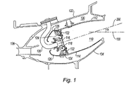
従来の分岐型燃焼チャンバは、燃焼チャンバの半分を示す軸状断面が図1に示され、その他の半分はエンジンの軸に対して対称の対部分である(図示せず)。燃焼チャンバ110は、外部ケーシング132と内部ケーシング134との間に画定される環状空間である拡散チャンバ130の下流に収容され、その中に圧縮機(図示せず)から上流で発生された圧縮された酸化剤、環境空気が、環状拡散導管136を経由して導かれる。
A conventional bifurcated combustion chamber is shown in FIG. 1 with an axial cross section showing half of the combustion chamber, and the other half is a symmetric pair with respect to the engine axis (not shown). The
この分岐型燃焼チャンバ110は、外部壁112および内部壁114の2つの同心壁を含み、これらは同軸であり実質的に円錐形である。壁は上流から下流方向へ広がる。燃焼チャンバ110の外部壁112および内部壁114はチャンバ端部壁116によって燃焼チャンバの上流側に向かって互いに連結される。
The bifurcated
チャンバ端部壁116は下流から上流方向へ広がる2つの実質的に横断面の間を延在する円錐台形部品である。チャンバ端部壁116は燃焼チャンバ110の外部壁112および内部壁114の各々に接続される。チャンバ端部壁116は小さな円錐角度を有する。それには噴射システム118が設けられ、それを通して燃焼反応が起きる燃焼チャンバ110の上流端部中に燃料を導入する噴射機120が通る。
The
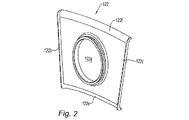
これらの燃焼反応の効果は、チャンバ端部壁116に向かって下流から上流方向へ熱を放射することである。したがって、動作中に、チャンバ端部壁は高温に曝される。それを保護するために、デフレクタ122としても知られる分割された熱遮蔽物が燃焼部位とチャンバ端部壁との間に挿入される。これらのデフレクタ122は、その1つが図2に示され、実質的にチャンバ端部壁116に溶接された平坦なプレートであり、噴射機の通過のための中心開口部122aを備える。それらは、チャンバ端部壁に対面する放射状縁部に沿って2つの側部バッフル122b、122cと、燃焼部位に対面する横断縁部に沿って空気を案内しチャンバの内部壁114および外部壁112のそれぞれに対して空間を形成する2つのタングを含む。デフレクタは、チャンバ端部壁116に穿孔された冷却オリフィス124を通って燃焼チャンバ110に入りそれに衝突する冷却空気のジェットによって冷却される。上流から下流方向へ流れるこれらのジェットを形成する空気は、チャンバ126の流れライニングによって案内され、冷却オリフィスを通ってチャンバ端部壁116を通過し、デフレクタ122の上流面に衝突する。次いで、空気は燃焼部位の内部および外部に向かって放射状に案内され、それぞれ壁114および112を冷却する膜の形成を開始する。
The effect of these combustion reactions is to radiate heat from the downstream toward the upstream toward the
デフレクタに沿うこの案内は放射状に導かれる側部バッフルによって行われる。これらのバッフルはまた、封止機能を行う。バッフルはチャンバ端部壁に接触し、または最小間隙を形成して、空気が2つの隣接するデフレクタ間に侵入して燃焼部位に入り、燃焼を妨害するのを防止する。そのような妨害は汚染に影響を与え、したがって回避すべきである。実際に起こり得ることは、特にクリアランス間隙が大きいエンジンのアイドリング速度で、この望ましくない冷気の侵入によって、COとCHx汚染物の排出に関する性能が悪化し易くなることである。 This guidance along the deflector is provided by side baffles that are guided radially. These baffles also perform a sealing function. The baffle contacts the chamber end wall or forms a minimum gap to prevent air from entering between the two adjacent deflectors and entering the combustion site to impede combustion. Such interference affects the contamination and should therefore be avoided. What can actually happen can be that this undesirable cold ingress tends to degrade performance with respect to CO and CHx contaminant emissions, particularly at engine idling speeds with large clearance gaps.
チャンバに空気と燃料を供給する手段の現在の発展により、噴射システムをチャンバ端部壁中に組み込む製造作業がますます困難になっている。例えば、多点噴射システムは、チャンバに流入する空気の大部分がそれらを通るので直径が増加し、したがって、チャンバ端部壁の周辺の空間の占有が増加し、2つの隣接システム間の間隙がますます小さくなる。 With the current development of means for supplying air and fuel to the chamber, manufacturing operations that incorporate the injection system into the chamber end walls have become increasingly difficult. For example, a multipoint injection system increases in diameter as most of the air entering the chamber passes through it, thus increasing the occupancy of the space around the chamber end wall and the gap between two adjacent systems. Increasingly smaller.
2つの隣接噴射機間の無用な領域を低減する観点から、同じチャンバについて噴射システムの数を増加させる必要があるとき、または替わりに、同じ数の噴射システムについてチャンバ端部壁の寸法が縮小されるとき、同様の状況が発生する。 From the point of view of reducing the unwanted area between two adjacent injectors, when the number of injection systems needs to be increased for the same chamber, or alternatively, the chamber end wall dimensions are reduced for the same number of injection systems. A similar situation occurs.
そのような場合において、デフレクタの中心開口部は互いに近接することになる。したがって、デフレクタに側部バッフルを形成するための空間は非常に小さい。 In such a case, the central openings of the deflectors will be close to each other. Therefore, the space for forming the side baffle on the deflector is very small.
図3および図4はこれらの状況に対して従来技術を適用することによって考えることのできる2つの解決策を示す。したがって、図3において、デフレクタ222は、デフレクタの縁部と開口部222aの縁部を形成するフランジ222a’との間の全領域B、Cを占める側部縁部の各々の側にバッフル222b、222cを有する。この解決策は、この追加の厚さのために封止を維持するが、この領域でデフレクタを冷却することはできないであろう。
3 and 4 show two solutions that can be envisaged by applying the prior art to these situations. Thus, in FIG. 3, the
図4において、解決策はデフレクタ322の側部縁部と開口部322aの縁部のフランジ322a’との間の臨界領域中のバッフル322b、322cを分断することである。形成された空間は、空気ジェットの衝突によるデフレクタの冷却を可能にするが、封止を犠牲にする。
In FIG. 4, the solution is to sever the
この問題を取り除くことが本発明の目的である。 It is an object of the present invention to eliminate this problem.
本発明によれば、ガスタービンエンジン用の環状燃焼チャンバは、外部壁と、内部壁と、これらの2つの壁を接続しチャンバ端部壁を構成する壁を含み、チャンバ端部壁には燃料噴射システムのための開口部が設けられ、熱遮蔽デフレクタが壁に固定され、デフレクタはこの燃料噴射システム用の上記開口部を中心とする開口部を備える平坦な壁部分と、2つの長手縁部と、2つの横断方向縁部を含み、デフレクタは、少なくとも1つの長手縁部に沿って連結カバーを形成するタングを含み、2つの縁部の間の連結を封止するように、隣接するデフレクタの縁部用にこの縁部に沿ってハウジングを形成し、このタングは、チャンバ端部壁中のオリフィスを経由して冷却空気が供給される空間を形成するように、チャンバ端部壁から離れている。 In accordance with the present invention, an annular combustion chamber for a gas turbine engine includes an outer wall, an inner wall, and a wall connecting the two walls to form a chamber end wall, the chamber end wall having a fuel An opening for the injection system is provided, a heat shield deflector is fixed to the wall, the deflector comprising a flat wall portion with an opening centered on the opening for the fuel injection system and two longitudinal edges And including two transverse edges, the deflector includes a tongue that forms a connecting cover along at least one longitudinal edge, and adjacent deflectors so as to seal the connection between the two edges A housing is formed along the edge for the edge of the chamber and the tongue is spaced from the chamber end wall to form a space to which cooling air is supplied via an orifice in the chamber end wall. ing
本発明の解決策によって、2つの隣接する開口部の間に存在する臨界領域は、両方とも連結カバーによって封止され、連結カバーが冷却空気の供給される空間を形成することが可能なので、冷却される。 By means of the solution of the invention, the critical region existing between two adjacent openings is both sealed by a connecting cover, which can form a space to which cooling air is supplied, so that cooling is possible. Is done.
さらに詳細には、チャンバは以下の特徴を有する。
ハウジングは壁の不連続性によって形成される。
デフレクタは、それらが噴射システム用開口部の縁部に着座する肩を含む。
肩は、チャンバ端部壁と燃料噴射用のシステムのための2つの隣接する開口部中に存在する領域中の連結カバーとの間に間隙を形成する。
デフレクタの横断縁部は湾曲した壁部分を含み、ハウジングはまたこの湾曲部分の長手縁部に沿って形成される。
デフレクタは、長手縁部に沿う連結カバー、および他の長手縁部に沿う連結カバーを含まない縁部を含み、2つの縁部は、縁対縁で配置された同様のデフレクタ縁部上に固定するように互いに補完し合う。
デフレクタの一部は両方の長手縁部に沿う連結カバーを含む。
デフレクタの一部は上記デフレクタの連結カバーを補完する2つの長手縁部を含む。
More specifically, the chamber has the following characteristics.
The housing is formed by wall discontinuities.
The deflectors include shoulders where they sit on the edge of the injection system opening.
The shoulder forms a gap between the chamber end wall and the connecting cover in the area present in the two adjacent openings for the system for fuel injection.
The transverse edge of the deflector includes a curved wall portion, and the housing is also formed along the longitudinal edge of the curved portion.
The deflector includes a connecting cover along the longitudinal edge, and an edge that does not include a connecting cover along the other longitudinal edge, the two edges being fixed on a similar deflector edge arranged in an edge-to-edge manner Complement each other.
A portion of the deflector includes a connecting cover along both longitudinal edges.
A portion of the deflector includes two longitudinal edges that complement the connecting cover of the deflector.
他の特徴および利点は、添付図面を参照する本発明のいくつかの実施形態の以下の説明から明らかになるであろう。 Other features and advantages will become apparent from the following description of several embodiments of the invention with reference to the accompanying drawings.
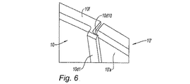
ここで、チャンバ端部壁中に並んで配置され耐火材料から作られたデフレクタ10および10’の間の封止の第1実施形態を示す、図5および図7を参照する。デフレクタ10は中心開口部10bを備える平坦部分10aを含み、図示されない噴射機のハウジングに相当する。図5において、開口部はチャンバ端部壁中に固定するためのフランジ10b1によって境界が作られる。デフレクタはエンジンの軸に対して放射方向に面する2つの長手縁部を含む。長手縁部10cおよび縁部10dは直線である。また、デフレクタ10は2つの横断縁部10eおよび10fを含み、両方とも燃焼チャンバの湾曲に従うために丸められ、空気を案内するために燃焼チャンバの内部に向かって湾曲する。図5の左側の縁部10cは直線であり、デフレクタの放射状輪郭に従う。他の側の縁部10dは、デフレクタの壁の後部面に延在するタング10d1から形成された、図5に見える面に対して不連続の後部を含む。この不連続性は隣接するデフレクタ10’の縁部10’c用の長手ハウジング10d10を形成する。このデフレクタ10’はデフレクタ10と同一である。デフレクタ10は平坦な部分10’a、2つの長手縁部10’cと10’d、および2つの丸められ湾曲した横断縁部10’eおよび10’fを含む。縁部10’dは、ハウジング10’d10を形成する長手タング10’d1を含む。
Reference is now made to FIGS. 5 and 7, which show a first embodiment of a seal between
図5から図7の実施例において、デフレクタは全て同一であり、図5および6には図示されないチャンバ端部壁16の周縁に搭載され、噴射システム用の開口部10b、10’bのフランジ10b1および10’b1によって固定される。デフレクタごとに1つの噴射システムが存在する。各デフレクタのタング10d1によって形成される連結カバーは、燃焼チャンバの膨張変化に順応する十分な幅で隣接するデフレクタ10’の縁部10’cを覆う。各ハウジング10d10、10’d10は、2つの隣接するデフレクタ間の漏洩がエンジン速度にかかわらず完全に除去されなくても低減されるように、隣接するデフレクタの縁部10c、10’cを保持するように設計される。
In the embodiment of FIGS. 5-7, the deflectors are all identical and are mounted on the periphery of the chamber end wall 16 (not shown in FIGS. 5 and 6) and have flanges 10b1 of the
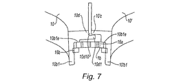
一方でデフレクタ10と10’の互いの配置、他方でチャンバ端部壁16の互いの配置を図7に断面で見ることができる。チャンバ端部壁中の隣接する開口部間の距離は非常に短いことに留意すべきである。デフレクタはそれぞれ肩10b1eおよび10’b1eを経由して開口部の縁部に着座する。デフレクタ10の壁は、隣接するデフレクタ10’の縁部10’cを覆うタング10d1によって縁部10dに沿って延在される。肩10b1eおよび10’b1eによってチャンバ端部壁16とデフレクタの後部面との間に空間が形成される。ジェットの形の空気は2つの開口部の間のチャンバ端部壁中に作られたオリフィス16aを通過する。デフレクタは、肩と一緒にチャンバ端部壁に対するクランプを形成するクリップ16bによってチャンバ端部壁に対して不動化されることに留意することができる。
The mutual arrangement of the
したがって、本発明の解決策はデフレクタ間の封止、および、噴射システムが通る開口部間に存在する狭い臨界領域中の空気ジェットの衝突による冷却の両方を提供することを可能にする。 The solution of the invention thus makes it possible to provide both a seal between the deflectors and a cooling by impingement of an air jet in a narrow critical region existing between the openings through which the injection system passes.
図5から図7の実施形態において、デフレクタは同一であるが、解決策は、第1のデフレクタ10が連結カバーをもたない第2デフレクタ10’の平面縁部10’cおよび10’dと協働して、2つの長手縁部に沿う連結カバー10c1および10d1を含む場合も包含する。効果は同じである。これは図8に示される。しかし、固定は異なる。それはより簡単であるが、2つの異なる設計の部品を製造する必要がある。
In the embodiment of FIGS. 5-7, the deflectors are the same, but the solution is that the
10、10’、222 デフレクタ
10b、122a 中心開口部
10a、10’a 平坦部分
10b、10’b、222a、322a 開口部
10c、10d、10’c、10’d 長手縁部
10c1、10d1 連結カバー
10e、10f、10’e、10’f 横断縁部
10d1、10’d1 タング
10b1e、10’b1e 肩
10d10、10’d10 ハウジング
16、116 チャンバ端部壁
16a オリフィス
16b クリップ
110 燃焼チャンバ
112 外部壁
114 内部壁
118 噴射システム
120 噴射機
122b、122c 側部バッフル
124 冷却オリフィス
126 流れライニング
130 拡散チャンバ
132 外部ケーシング
134 内部ケーシング
136 環状拡散導管
222a’、322a’、10b1、10’b1 フランジ
222b、222c バッフル
10, 10 ', 222
Claims (9)
Applications Claiming Priority (2)
| Application Number | Priority Date | Filing Date | Title |
|---|---|---|---|
| FR0704828 | 2007-07-04 | ||
| FR0704828A FR2918443B1 (en) | 2007-07-04 | 2007-07-04 | COMBUSTION CHAMBER COMPRISING THERMAL PROTECTION DEFLECTORS OF BOTTOM BOTTOM AND GAS TURBINE ENGINE BEING EQUIPPED |
Publications (2)
| Publication Number | Publication Date |
|---|---|
| JP2009014337A JP2009014337A (en) | 2009-01-22 |
| JP5225769B2 true JP5225769B2 (en) | 2013-07-03 |
Family
ID=38982783
Family Applications (1)
| Application Number | Title | Priority Date | Filing Date |
|---|---|---|---|
| JP2008174223A Active JP5225769B2 (en) | 2007-07-04 | 2008-07-03 | Combustion chamber including chamber end wall heat shield deflector and gas turbine engine comprising the same |
Country Status (6)
| Country | Link |
|---|---|
| US (1) | US8096134B2 (en) |
| EP (1) | EP2012062B1 (en) |
| JP (1) | JP5225769B2 (en) |
| CA (1) | CA2636661C (en) |
| FR (1) | FR2918443B1 (en) |
| RU (1) | RU2485404C2 (en) |
Families Citing this family (13)
| Publication number | Priority date | Publication date | Assignee | Title |
|---|---|---|---|---|
| FR2910115B1 (en) * | 2006-12-19 | 2012-11-16 | Snecma | DEFLECTOR FOR BOTTOM OF COMBUSTION CHAMBER, COMBUSTION CHAMBER WHERE IT IS EQUIPPED AND TURBOREACTOR COMPRISING THEM |
| FR2918444B1 (en) * | 2007-07-05 | 2013-06-28 | Snecma | CHAMBER BOTTOM DEFLECTOR, COMBUSTION CHAMBER COMPRISING SAME, AND GAS TURBINE ENGINE WHERE IT IS EQUIPPED |
| US8863530B2 (en) | 2008-10-30 | 2014-10-21 | Power Generation Technologies Development Fund L.P. | Toroidal boundary layer gas turbine |
| US9052116B2 (en) | 2008-10-30 | 2015-06-09 | Power Generation Technologies Development Fund, L.P. | Toroidal heat exchanger |
| US8495881B2 (en) * | 2009-06-02 | 2013-07-30 | General Electric Company | System and method for thermal control in a cap of a gas turbine combustor |
| DE102011014670A1 (en) | 2011-03-22 | 2012-09-27 | Rolls-Royce Deutschland Ltd & Co Kg | Segmented combustion chamber head |
| US9021812B2 (en) | 2012-07-27 | 2015-05-05 | Honeywell International Inc. | Combustor dome and heat-shield assembly |
| WO2015038232A1 (en) | 2013-09-13 | 2015-03-19 | United Technologies Corporation | Sealed combustor liner panel for a gas turbine engine |
| US10578021B2 (en) * | 2015-06-26 | 2020-03-03 | Delavan Inc | Combustion systems |
| FR3078384B1 (en) | 2018-02-28 | 2021-05-28 | Safran Aircraft Engines | DOUBLE BOTTOM COMBUSTION CHAMBER |
| FR3081974B1 (en) * | 2018-06-04 | 2020-06-19 | Safran Aircraft Engines | COMBUSTION CHAMBER OF A TURBOMACHINE |
| RU208130U1 (en) * | 2021-04-26 | 2021-12-06 | Публичное Акционерное Общество "Одк-Сатурн" | COMBUSTION CHAMBER FRONT WALL |
| CN115342382A (en) * | 2022-07-26 | 2022-11-15 | 清航空天(北京)科技有限公司 | Single-channel oxygen supply detonation combustion chamber module and detonation combustion chamber |
Family Cites Families (32)
| Publication number | Priority date | Publication date | Assignee | Title |
|---|---|---|---|---|
| SU352573A1 (en) * | 1970-10-05 | 1983-06-23 | Pinchuk V V | Annular combustion chamber of gas turbine engine |
| US4180974A (en) * | 1977-10-31 | 1980-01-01 | General Electric Company | Combustor dome sleeve |
| US4380896A (en) * | 1980-09-22 | 1983-04-26 | The United States Of America As Represented By The Secretary Of The Army | Annular combustor having ceramic liner |
| US4567730A (en) * | 1983-10-03 | 1986-02-04 | General Electric Company | Shielded combustor |
| US5012645A (en) * | 1987-08-03 | 1991-05-07 | United Technologies Corporation | Combustor liner construction for gas turbine engine |
| US4843825A (en) * | 1988-05-16 | 1989-07-04 | United Technologies Corporation | Combustor dome heat shield |
| US4934145A (en) * | 1988-10-12 | 1990-06-19 | United Technologies Corporation | Combustor bulkhead heat shield assembly |
| SU1760254A1 (en) * | 1990-06-15 | 1992-09-07 | Уфимский Институт Им.Серго Орджоникидзе | Dust system |
| GB9018014D0 (en) * | 1990-08-16 | 1990-10-03 | Rolls Royce Plc | Gas turbine engine combustor |
| GB9018013D0 (en) * | 1990-08-16 | 1990-10-03 | Rolls Royce Plc | Gas turbine engine combustor |
| GB2257781B (en) * | 1991-04-30 | 1995-04-12 | Rolls Royce Plc | Combustion chamber assembly in a gas turbine engine |
| GB2287310B (en) * | 1994-03-01 | 1997-12-03 | Rolls Royce Plc | Gas turbine engine combustor heatshield |
| DE4427222A1 (en) * | 1994-08-01 | 1996-02-08 | Bmw Rolls Royce Gmbh | Heat shield for a gas turbine combustor |
| US5524438A (en) * | 1994-12-15 | 1996-06-11 | United Technologies Corporation | Segmented bulkhead liner for a gas turbine combustor |
| DE19508111A1 (en) * | 1995-03-08 | 1996-09-12 | Bmw Rolls Royce Gmbh | Heat shield arrangement for a gas turbine combustor |
| FR2751731B1 (en) * | 1996-07-25 | 1998-09-04 | Snecma | BOWL DEFLECTOR ASSEMBLY FOR A TURBOMACHINE COMBUSTION CHAMBER |
| US5974805A (en) * | 1997-10-28 | 1999-11-02 | Rolls-Royce Plc | Heat shielding for a turbine combustor |
| US6164074A (en) * | 1997-12-12 | 2000-12-26 | United Technologies Corporation | Combustor bulkhead with improved cooling and air recirculation zone |
| DE29815101U1 (en) * | 1998-08-22 | 2000-05-31 | Dimbath, Wolfgang, 91052 Erlangen | Reusable case for a wind instrument |
| EP1118806A1 (en) * | 2000-01-20 | 2001-07-25 | Siemens Aktiengesellschaft | Thermally charged wall structure and method to seal gaps in such a structure |
| US6606861B2 (en) * | 2001-02-26 | 2003-08-19 | United Technologies Corporation | Low emissions combustor for a gas turbine engine |
| US6497105B1 (en) * | 2001-06-04 | 2002-12-24 | Pratt & Whitney Canada Corp. | Low cost combustor burner collar |
| US6952927B2 (en) * | 2003-05-29 | 2005-10-11 | General Electric Company | Multiport dome baffle |
| US7121095B2 (en) * | 2003-08-11 | 2006-10-17 | General Electric Company | Combustor dome assembly of a gas turbine engine having improved deflector plates |
| US7363763B2 (en) * | 2003-10-23 | 2008-04-29 | United Technologies Corporation | Combustor |
| US7673460B2 (en) * | 2005-06-07 | 2010-03-09 | Snecma | System of attaching an injection system to a turbojet combustion chamber base |
| FR2897144B1 (en) * | 2006-02-08 | 2008-05-02 | Snecma Sa | COMBUSTION CHAMBER FOR TURBOMACHINE WITH TANGENTIAL SLOTS |
| FR2897417A1 (en) * | 2006-02-10 | 2007-08-17 | Snecma Sa | ANNULAR COMBUSTION CHAMBER OF A TURBOMACHINE |
| FR2897922B1 (en) * | 2006-02-27 | 2008-10-10 | Snecma Sa | ARRANGEMENT FOR A TURBOREACTOR COMBUSTION CHAMBER |
| FR2903171B1 (en) * | 2006-06-29 | 2008-10-17 | Snecma Sa | CRABOT LINK ARRANGEMENT FOR TURBOMACHINE COMBUSTION CHAMBER |
| FR2909748B1 (en) * | 2006-12-07 | 2009-07-10 | Snecma Sa | BOTTOM BOTTOM, METHOD OF MAKING SAME, COMBUSTION CHAMBER COMPRISING SAME, AND TURBOJET ENGINE |
| FR2914399B1 (en) * | 2007-03-27 | 2009-10-02 | Snecma Sa | FURNITURE FOR BOTTOM OF COMBUSTION CHAMBER. |
-
2007
- 2007-07-04 FR FR0704828A patent/FR2918443B1/en active Active
-
2008
- 2008-07-03 RU RU2008127151/06A patent/RU2485404C2/en active
- 2008-07-03 JP JP2008174223A patent/JP5225769B2/en active Active
- 2008-07-03 US US12/167,542 patent/US8096134B2/en active Active
- 2008-07-04 CA CA2636661A patent/CA2636661C/en active Active
- 2008-07-04 EP EP08159738.7A patent/EP2012062B1/en active Active
Also Published As
| Publication number | Publication date |
|---|---|
| FR2918443B1 (en) | 2009-10-30 |
| EP2012062A1 (en) | 2009-01-07 |
| FR2918443A1 (en) | 2009-01-09 |
| US20090013694A1 (en) | 2009-01-15 |
| CA2636661C (en) | 2015-11-24 |
| RU2008127151A (en) | 2010-01-10 |
| EP2012062B1 (en) | 2019-08-28 |
| RU2485404C2 (en) | 2013-06-20 |
| JP2009014337A (en) | 2009-01-22 |
| CA2636661A1 (en) | 2009-01-04 |
| US8096134B2 (en) | 2012-01-17 |
Similar Documents
| Publication | Publication Date | Title |
|---|---|---|
| JP5225769B2 (en) | Combustion chamber including chamber end wall heat shield deflector and gas turbine engine comprising the same | |
| US8683806B2 (en) | Chamber-bottom baffle, combustion chamber comprising same and gas turbine engine fitted therewith | |
| US10513987B2 (en) | System for dissipating fuel egress in fuel supply conduit assemblies | |
| US8726631B2 (en) | Dual walled combustors with impingement cooled igniters | |
| US10094564B2 (en) | Combustor dilution hole cooling system | |
| EP3396252B1 (en) | Fuel injection device | |
| US10041675B2 (en) | Multiple ventilated rails for sealing of combustor heat shields | |
| CN1683772B (en) | turbo ring | |
| EP2325563B1 (en) | Dual walled combustor with improved liner seal | |
| US8387395B2 (en) | Annular combustion chamber for a turbomachine | |
| TWI641757B (en) | Burner separator, burner, combustion device, gas turbine, and method for cooling burner separator | |
| US20140190171A1 (en) | Combustors with hybrid walled liners | |
| RU2667849C2 (en) | Turbomachine combustion chamber provided with air deflection means for reducing wake created by ignition plug | |
| JP2006002764A (en) | Installation of high-pressure turbine nozzle in leakage-proof mode at one end of combustion chamber in gas turbine | |
| EP3839348B1 (en) | Combustor panel and method for cooling the same | |
| US8490401B2 (en) | Annular combustion chamber for a gas turbine engine | |
| US8156744B2 (en) | Annular combustion chamber for a gas turbine engine | |
| CN103291457A (en) | Transition piece aft frame assembly having a heat shield | |
| JP6188937B2 (en) | Seal assembly for a gap between the exit portions of adjacent transition ducts in a gas turbine engine | |
| JP2008180496A (en) | Gas turbine engine diffuser and combustion chamber and gas turbine engine comprising them | |
| US9097119B2 (en) | Transitional region for a secondary combustion chamber of a gas turbine | |
| JP2014148964A (en) | Gas turbine tail cylinder seal and gas turbine | |
| US20250172293A1 (en) | Assembly, method for manufacturing assembly, burner, and method for manufacturing burner | |
| JPH1163499A (en) | Gas turbine combustor |
Legal Events
| Date | Code | Title | Description |
|---|---|---|---|
| A621 | Written request for application examination |
Free format text: JAPANESE INTERMEDIATE CODE: A621 Effective date: 20110621 |
|
| A977 | Report on retrieval |
Free format text: JAPANESE INTERMEDIATE CODE: A971007 Effective date: 20120423 |
|
| A131 | Notification of reasons for refusal |
Free format text: JAPANESE INTERMEDIATE CODE: A131 Effective date: 20120515 |
|
| A521 | Request for written amendment filed |
Free format text: JAPANESE INTERMEDIATE CODE: A523 Effective date: 20120814 |
|
| RD02 | Notification of acceptance of power of attorney |
Free format text: JAPANESE INTERMEDIATE CODE: A7422 Effective date: 20121107 |
|
| RD04 | Notification of resignation of power of attorney |
Free format text: JAPANESE INTERMEDIATE CODE: A7424 Effective date: 20121210 |
|
| TRDD | Decision of grant or rejection written | ||
| A01 | Written decision to grant a patent or to grant a registration (utility model) |
Free format text: JAPANESE INTERMEDIATE CODE: A01 Effective date: 20130219 |
|
| A61 | First payment of annual fees (during grant procedure) |
Free format text: JAPANESE INTERMEDIATE CODE: A61 Effective date: 20130313 |
|
| R150 | Certificate of patent or registration of utility model |
Ref document number: 5225769 Country of ref document: JP Free format text: JAPANESE INTERMEDIATE CODE: R150 Free format text: JAPANESE INTERMEDIATE CODE: R150 |
|
| FPAY | Renewal fee payment (event date is renewal date of database) |
Free format text: PAYMENT UNTIL: 20160322 Year of fee payment: 3 |
|
| R250 | Receipt of annual fees |
Free format text: JAPANESE INTERMEDIATE CODE: R250 |
|
| R250 | Receipt of annual fees |
Free format text: JAPANESE INTERMEDIATE CODE: R250 |
|
| R250 | Receipt of annual fees |
Free format text: JAPANESE INTERMEDIATE CODE: R250 |
|
| R250 | Receipt of annual fees |
Free format text: JAPANESE INTERMEDIATE CODE: R250 |
|
| R250 | Receipt of annual fees |
Free format text: JAPANESE INTERMEDIATE CODE: R250 |
|
| R250 | Receipt of annual fees |
Free format text: JAPANESE INTERMEDIATE CODE: R250 |
|
| R250 | Receipt of annual fees |
Free format text: JAPANESE INTERMEDIATE CODE: R250 |
|
| R250 | Receipt of annual fees |
Free format text: JAPANESE INTERMEDIATE CODE: R250 |
|
| R250 | Receipt of annual fees |
Free format text: JAPANESE INTERMEDIATE CODE: R250 |
|
| R250 | Receipt of annual fees |
Free format text: JAPANESE INTERMEDIATE CODE: R250 |
|
| R250 | Receipt of annual fees |
Free format text: JAPANESE INTERMEDIATE CODE: R250 |