JP5225729B2 - Joining method of joined body - Google Patents
Joining method of joined body Download PDFInfo
- Publication number
- JP5225729B2 JP5225729B2 JP2008093418A JP2008093418A JP5225729B2 JP 5225729 B2 JP5225729 B2 JP 5225729B2 JP 2008093418 A JP2008093418 A JP 2008093418A JP 2008093418 A JP2008093418 A JP 2008093418A JP 5225729 B2 JP5225729 B2 JP 5225729B2
- Authority
- JP
- Japan
- Prior art keywords
- joined
- bonding
- joining
- bonded
- sintered body
- Prior art date
- Legal status (The legal status is an assumption and is not a legal conclusion. Google has not performed a legal analysis and makes no representation as to the accuracy of the status listed.)
- Expired - Fee Related
Links
Images


Landscapes
- Cutting Tools, Boring Holders, And Turrets (AREA)
Description
本発明は、接合体の接合方法に関するものであり、特に、切削工具に好適な接合体の接合方法に関する。 The present invention relates to a joined method for joined bodies, and more particularly, to a joined method for joined bodies suitable for a cutting tool.
従来より、cBN(立方晶窒化硼素)もしくはダイヤモンド切削工具に代表されるように、先端に高硬度材料をロウ付けにより接合した切削工具が製造されており、特殊鋼材その他各種の切削加工に利用されている。 Conventionally, as represented by cBN (cubic boron nitride) or diamond cutting tools, cutting tools with high-hardness material joined by brazing at the tip have been manufactured and used for special steel and other various cutting processes. ing.
具体的には、例えば、cBNと超硬合金をロウ付けにより接合した工具が製造・販売されている(例えば、非特許文献1)。あるいは、PCD(焼結ダイヤモンド)またはcBNと、セラミックスまたはサーメットとをロウ付けにより接合した接合体が提案されている(例えば、特許文献1、特許文献2)。また、超硬合金またはサーメットと、高速度鋼等とを、Cuロウ材を用いたロウ付けにより接合した切削工具も提案されている(例えば、特許文献3)。
しかし、ロウ材の多くは、700〜800℃程度で液相が現れる。このため、ロウ付けによる接合体を用いた切削工具は、切削中に前述の温度を超えるおそれのある高速切削等には、使用することが困難であった。また、ロウ付け時に生成した液相が、浸み出して被接合材を汚し、後工程である加工時に悪影響を与えることがあった。 However, in many of the brazing materials, a liquid phase appears at about 700 to 800 ° C. For this reason, it has been difficult to use a cutting tool using a joined body by brazing for high-speed cutting or the like that may exceed the aforementioned temperature during cutting. Moreover, the liquid phase produced | generated at the time of brazing oozes and soils a to-be-joined material, and had a bad influence at the time of the process which is a post process.
また、接合体の耐摩耗性を向上するために、コーティング処理が施される場合があるが、前述の温度を超える高温を必要とするコーティング(例えば、CVDコーティングでは、1000℃以上を必要とする)処理を行うことも困難であった。 Further, in order to improve the wear resistance of the joined body, a coating treatment may be performed. However, a coating that requires a high temperature exceeding the above-described temperature (for example, a CVD coating requires 1000 ° C. or more). ) Processing was also difficult.
本発明は、上記の問題に鑑み、切削中に、ロウ材が液相を生成する温度を超える高温となっても、接合層の接合強度が低下することのない、高速切削やCVDコーティング処理等に適した切削工具として好適な接合体の接合方法を提供することを課題とする。 In view of the above problems, the present invention provides high-speed cutting, CVD coating processing, or the like in which the bonding strength of the bonding layer does not decrease even when the temperature exceeds the temperature at which the brazing material generates a liquid phase during cutting. It is an object of the present invention to provide a method for joining joined bodies suitable as a cutting tool suitable for the above.
本発明者は、鋭意検討の結果、以下に述べる各請求項の発明により、上記課題が解決できることを見出した。
以下、各請求項の発明につき説明する。
As a result of intensive studies, the present inventor has found that the above-described problems can be solved by the inventions of the claims described below.
The invention of each claim will be described below.
請求項1に記載の発明は、
サーメット焼結体を第1の被接合材とし、cBN焼結体またはダイヤモンド焼結体を第2の被接合材とする接合体の接合方法であって、前記第1の被接合材および第2の被接合材を、両者の間に設置された1000℃未満では液相を生成しない接合材を介して接合し、前記接合は0.1MPa〜200MPaの圧力で加圧しながら通電加熱することによって行い、
前記第2の被接合材よりも前記第1の被接合材を集中的に通電加熱して、前記第1の被接合材を、前記第2の被接合材よりも優先的に発熱させて接合することを特徴とする接合体の接合方法である。
The invention described in
A joining method of a joined body using a cermet sintered body as a first material to be joined and a cBN sintered body or a diamond sintered body as a second material to be joined, wherein the first and second materials are joined. lines by the welded material, is less than 1000 ° C. disposed therebetween and bonded by means of a bonding material which does not generate a liquid phase, said bonding energized heating under a pressure of 0.1MPa~200MPa of Yes ,
The second concentrated energized heating the first material to be joined than the welded material, wherein the first material to be joined, the second and preferentially by heating than the welded material joined the to Rukoto a bonding method of the bonded body, characterized.
請求項1の発明においては、焼結済みのサーメット焼結体からなる第1の被接合材と焼結済みのcBN焼結体またはダイヤモンド焼結体からなる第2の被接合材を、両者の間に設置された1000℃未満では液相を生成しない接合材により接合している。このため、この接合体を切削工具として使用して、切削作業を行った場合、作業中に800℃を超える高温となっても、接合層が液相を生成せず、接合強度が低下することがない。従って、1000℃以上となる高速切削に好適な切削工具等を提供することができる。 In the first aspect of the invention, the first material to be joined made of a sintered cermet sintered body and the second material to be joined made of a sintered cBN sintered body or diamond sintered body are used. in less than 1000 ℃ placed between they are joined by a joining material that does not generate liquid phase. For this reason, when this joined body is used as a cutting tool and a cutting operation is performed, even if the temperature exceeds 800 ° C. during the operation, the bonding layer does not generate a liquid phase and the bonding strength is reduced. There is no. Therefore, it is possible to provide a cutting tool suitable for high-speed cutting at 1000 ° C. or higher.
また、この結果、接合体に1000℃程度の温度で被覆を行うCVDコーティング等を施すことが可能となる。このため、例えば、従来適用が不可能であったcBN工具やダイヤモンド工具へのCVDコーティングが可能となり、さらなる長寿命化や多品種の被切削材料へ対応することが可能となる。なお、この場合、接合層は、CVDコーティングの温度より少し高い温度では液相を生成しない接合層であることが好ましい。これは、CVDコーティング時の急激な温度変化等による接合層の変形、さらに接合強度の低下への影響をより少なくすることができるからである。 As a result, it is possible to perform CVD coating or the like for coating the joined body at a temperature of about 1000 ° C. For this reason, for example, CVD coating can be applied to cBN tools and diamond tools, which could not be applied conventionally, and it is possible to further extend the life and to cope with various kinds of materials to be cut. In this case, the bonding layer is preferably a bonding layer that does not generate a liquid phase at a temperature slightly higher than the temperature of the CVD coating. This is because the influence on the deformation of the bonding layer due to a rapid temperature change or the like during the CVD coating, and the decrease in the bonding strength can be reduced.
また、本発明におけるサーメットとは、チタン(Ti)の炭化物、窒化物、炭窒化物および/またはTiの炭化物、窒化物、炭窒化物を主成分とし、周期律表4a、5a、6a族の炭化物、窒化物、炭窒化物のうちの少なくとも1種とからなる硬質相と、鉄族金属を主たる結合相とする硬質合金をいう。 The cermet in the present invention is mainly composed of titanium (Ti) carbides, nitrides, carbonitrides and / or Ti carbides, nitrides, carbonitrides, and is based on the periodic table 4a, 5a, 6a group. It refers to a hard alloy composed of at least one of carbide, nitride, and carbonitride and an iron group metal as a main binder phase.
本発明においては、上記したように、第1の被接合材としてチタン系化合物(炭化物、窒化物等)を主たる硬質相とする複合材料であるサーメット焼結体を用いているため、WCを主たる硬質相とする超硬合金焼結体を第1の被接合材として用いる場合に比べ、希少金属であるタングステン(W)の使用量を低減することができる。 In the present invention, as described above, since the cermet sintered body which is a composite material having a titanium-based compound (carbide, nitride, etc.) as a main hard phase is used as the first bonded material, WC is mainly used. Compared with the case where a cemented carbide sintered body having a hard phase is used as the first material to be bonded, the amount of tungsten (W), which is a rare metal, can be reduced.
また、従来のロウ付け接合においては、サーメット焼結体に熱亀裂が発生しやすく被接合材として用いることが困難であった。また、第2の被接合材であるcBN焼結体やダイヤモンド焼結体は熱に弱く、高温で分解されやすいため、短時間で熱劣化しやすい。このため、1000℃以上で液相を生成する接合材を用いて、ロウ付け接合により第1の被接合材と第2の被接合材との接合体を得ることは困難であった。 Further, in the conventional brazing joint, a thermal crack is easily generated in the cermet sintered body, and it is difficult to use it as a material to be joined. In addition, the cBN sintered body and the diamond sintered body, which are the second material to be joined, are vulnerable to heat and are easily decomposed at high temperatures, and thus are easily thermally deteriorated in a short time. For this reason, it was difficult to obtain a joined body of the first material to be joined and the second material to be joined by brazing using a joining material that generates a liquid phase at 1000 ° C. or higher.
しかし、請求項1の発明では、接合は、第1の被接合材と第2の被接合材の間に0.1MPa〜200MPaの加圧力を働かせながら通電加熱することによって接合しているため、数秒〜数分以内の極めて短時間で、接合面近傍のみを加熱して強固な接合を得ることができる。この結果、高圧安定型の材料であるcBN焼結体やダイヤモンド焼結体の品質を劣化させることなく、またサーメット焼結体に熱亀裂を発生させることなく、1000℃未満では液相を生成しない接合材を用いてサーメットと接合することが可能となる。
However, according to the invention of
加圧力が小さすぎると、被接合材であるcBN焼結体やダイヤモンド焼結体およびサーメット焼結体と電極との間の接触抵抗が多くなり、電流を流せないあるいは放電する等の問題がある。一方、加圧力が大きすぎると、cBN焼結体やサーメット焼結体が割れる等の問題がある。請求項1の発明においては、好ましい加圧力として、0.1MPa〜200MPaの加圧力としたため、これらの問題が発生せず、好ましい接合体を得ることができる。1MPa〜100MPaであると、適度な接触抵抗となり、接合面での発熱が効率的に行われるためより好ましく、10MPa〜70MPaであると、さらに接触抵抗が適切になると共に、さらに被接合体が割れにくくなるため、さらに好ましい。 If the applied pressure is too small, the contact resistance between the cBN sintered body, the diamond sintered body, and the cermet sintered body, which are the materials to be joined, and the electrode increases, and there is a problem that current cannot flow or discharge. . On the other hand, if the applied pressure is too large, there is a problem that the cBN sintered body and the cermet sintered body break. In the first aspect of the present invention, since a preferable pressure is 0.1 MPa to 200 MPa, these problems do not occur and a preferable joined body can be obtained. When the pressure is 1 MPa to 100 MPa, an appropriate contact resistance is obtained, and heat generation at the joining surface is efficiently performed, and thus more preferable, and when the pressure is 10 MPa to 70 MPa, the contact resistance is further appropriate, and the joined body is further cracked. Since it becomes difficult, it is more preferable.
そして、本請求項に係る接合体の接合方法は、さらに、
前記通電加熱によって、前記第1の被接合材を、前記第2の被接合材よりも優先的に発熱させて接合することを特徴とする。
And the joining method of the joined object concerning this claim further,
Wherein the electrical heating, the first material to be joined, wherein preferentially by heating than the second material to be joined, characterized that you joined.
即ち、請求項1の発明においては、第1の被接合材であるサーメット焼結体を、第2の被接合材であるcBN焼結体やダイヤモンド焼結体よりも優先的に発熱させて接合する。一般に、cBN焼結体やダイヤモンド焼結体はサーメット焼結体よりも電気抵抗が高いため、通電加熱時、第2の被接合材であるcBN焼結体やダイヤモンド焼結体が第1の被接合材であるサーメット焼結体よりも優先的に発熱し、cBN焼結体やダイヤモンド焼結体の品質劣化(熱的劣化、分解、亀裂生成等)を招くことがある。
That is, in the invention of
このような第2の被接合材の品質劣化の発生を防ぐためには、通電加熱時、第2の被接合材よりも第1の被接合材が優先的に発熱するように、第2の被接合材と接合材の配置、通電方法を工夫する必要がある。具体的には、例えば、第2の被接合材に接する電極と第1の被接合材に接する電極の材質を変えることが挙げられる。電極の材質を変えることにより、第1の被接合材と第2の被接合材の各々に流れる電流の量が異なるため、それぞれの発熱を制御することができる。また、第2の被接合材よりも第1の被接合材を集中的に通電加熱して、間接的に第2の被接合材を加熱してもよい。 In order to prevent such quality deterioration of the second bonded material, the second bonded material is heated so that the first bonded material generates heat preferentially over the second bonded material during energization heating. It is necessary to devise the bonding material, the arrangement of the bonding material, and the energization method. Specifically, for example, the materials of the electrode in contact with the second bonded material and the electrode in contact with the first bonded material can be changed. By changing the material of the electrode, the amount of current flowing through each of the first material to be bonded and the second material to be bonded is different, so that each heat generation can be controlled. Alternatively, the first material to be bonded may be heated more intensively than the second material to be bonded, and the second material to be bonded may be indirectly heated.
このように、通電経路を工夫することにより、第1の被接合材を第2の被接合材よりも優先的に加熱することができる。この結果、第2の被接合材であるcBN焼結体やダイヤモンド焼結体を必要以上に高温加熱することなく、短時間、具体的には、例えば、1分以内、好ましくは30秒以内で接合材近傍を高温加熱することができるため、強固な接合が可能になると共に、cBN焼結体やダイヤモンド焼結体の品質劣化(熱的劣化、分解、亀裂生成等)を招くことなく、cBN焼結体やダイヤモンド焼結体の高硬度等の特徴を十分に生かすことができる。 Thus, by devising the energization path, the first material to be bonded can be preferentially heated over the second material to be bonded. As a result, the cBN sintered body and the diamond sintered body, which are the second materials to be joined, are heated in a short time, specifically within, for example, within 1 minute, preferably within 30 seconds without being heated at a higher temperature than necessary. Since the vicinity of the bonding material can be heated at a high temperature, strong bonding is possible, and cBN is not deteriorated (thermal deterioration, decomposition, crack generation, etc.) without causing quality deterioration of the cBN sintered body or diamond sintered body. Features such as high hardness of the sintered body and the diamond sintered body can be fully utilized.
請求項2に記載の発明は、
通電加熱によって、前記接合材成分のうちの少なくとも1つの元素を、前記第1の被接合材および/または前記第2の被接合材中に元素拡散させることを特徴とする請求項1に記載の接合体の接合方法である。
The invention described in
By electric heating, wherein at least one element of the joining material components, in
請求項2の発明においては、接合材成分のうちの少なくとも1つの元素を、第1の被接合材や第2の被接合材中に元素拡散させているため、第1の被接合材や第2の被接合材との接合がより効率的に行われ、接合強度のより高い接合体を得ることができる。
In the invention of
請求項3に記載の発明は、
加圧しながらの通電加熱によって変形する接合材を用いて接合することを特徴とする請求項1または請求項2に記載の接合体の接合方法である。
The invention according to
Is a bonding method of assembly according to
請求項3の発明においては、加圧しながら通電加熱することによって変形する接合材を用いているため、接合材の変形に伴う物質の移動が、被接合材と接合材との界面の結合に有効に働き、接合強度の高い接合体を得ることができる。また、加圧しながら通電加熱することにより、接合材は被接合材の形状に合わせて変形するようになるため、接着面積の増大を図ることができ、接合強度の向上効果を得ることができる。
In the invention of
請求項4に記載の発明は、
前記接合材が、チタン(Ti)、コバルト(Co)、ニッケル(Ni)のいずれか、または前記金属の少なくとも1つを含む合金からなることを特徴とする請求項1ないし請求項3のいずれかに記載の接合体の接合方法である。
The invention according to
4. The bonding material according to
請求項4の発明においては、一般に第1の被接合材であるサーメット焼結体や第2の被接合材であるcBN焼結体やダイヤモンド焼結体の結合相成分として用いられ、液相を生成する温度が1400℃以上であるTi、Co、Niの、少なくともいずれかを含んでいるため、接合強度のより高い接合体を得ることができる。
In the invention of
請求項5に記載の発明は、
前記接合材が、チタン(Ti)を含むことを特徴とする請求項4に記載の接合体の接合方法である。
The invention described in
The joining method according to
請求項5の発明においては、第2の被接合材であるcBN焼結体やダイヤモンド焼結体の結合相成分として用いられるTiを含む材料を接合材としているため、接合材中のTiが容易に第1の被接合材や第2の被接合材に元素拡散し、強固な接合を得ることができる。さらに、Tiと結合して金属間化合物を形成する材料を使用することにより、接合材が液相を生成する温度のさらなる上昇と、高強度化が可能となり好ましい。
In the invention of
Tiと結合して金属間化合物を形成する元素としては、例えば、Siを挙げることができる。金属間化合物は、接合材に最初から含まれていても良い。また、金属間化合物を構成する元素が、接合材には別の状態で含まれており、接合完了後に反応生成されても良い。金属間化合物が反応生成される場合は、接合に反応熱を利用することができるため、接合にとってより有効である。 Examples of the element that forms an intermetallic compound by combining with Ti include Si. The intermetallic compound may be contained in the bonding material from the beginning. Moreover, the element which comprises an intermetallic compound is contained in another state in the bonding | jointing material, and it may produce | generate by reaction after the completion of joining. When an intermetallic compound is produced by reaction, reaction heat can be used for joining, which is more effective for joining.
請求項6に記載の発明は、
前記接合材が、前記第1の被接合材よりも低温で液相を生成することを特徴とする請求項1ないし請求項5のいずれかに記載の接合体の接合方法である。
The invention described in claim 6
The joining method for a joined body according to any one of
請求項6の発明においては、接合材が第1の被接合材よりも低温で液相を生成することにより、加圧しながら通電加熱を行ったとき、第1の被接合材が大きく変形する前に接合体が変形するため、接合による第1の被接合材の形状変化を防ぎながら接合を行うことができる。このような接合材としては、例えば、Ti−Co合金、Ti−Ni合金等を挙げることができる。 In invention of Claim 6, when joining material produces | generates a liquid phase at low temperature rather than a 1st to-be-joined material, when it heats and supplies with electricity, before a 1st to-be-joined material deform | transforms greatly. Since the joined body is deformed, the joining can be performed while preventing the shape change of the first material to be joined due to joining. Examples of such a bonding material include a Ti—Co alloy, a Ti—Ni alloy, and the like.
請求項7に記載の発明は、
前記接合材の少なくとも一部が、通電加熱時に液相を生成していることを特徴とする請求項6に記載の接合体の接合方法である。
The invention described in claim 7
The joining method for a joined body according to claim 6, wherein at least a part of the joining material generates a liquid phase during energization heating.
請求項7の発明においては、接合材の少なくとも一部が、通電加熱時に液相を生成しているため、接合体成分が第1の被接合材や第2の被接合材に元素拡散しやすく、第1の被接合材と第2の被接合材を強固に接合できる。 In the invention of claim 7, since at least a part of the bonding material generates a liquid phase at the time of energization heating, the bonded component easily diffuses into the first bonded material and the second bonded material. The 1st to-be-joined material and the 2nd to-be-joined material can be joined firmly.
請求項8の発明は、
前記接合材および/または前記第1の被接合材の結合相に含まれるニッケル(Ni)が、30vol%(体積百分率)以下であることを特徴とする請求項1ないし請求項7のいずれかに記載の接合体の接合方法である。
The invention of claim 8
The nickel (Ni) contained in the binder phase of the bonding material and / or the first bonded material is 30 vol% (volume percentage) or less, according to any one of
請求項8の発明においては、接合材や第1の被接合材の結合相に含まれるニッケル(Ni)を30vol%以下としている。これは、30vol%を超えると、接合体にCVDコーティングを施す際、CVDコーティング材料として用いられる塩素ガスと接合材やサーメット焼結体とが反応してCVD膜が異常成長し、接合層の性能劣化を引き起こす可能性が高いからである。 In invention of Claim 8, nickel (Ni) contained in the binder phase of a joining material or a 1st to-be-joined material shall be 30 vol% or less. If the volume exceeds 30 vol%, when CVD coating is applied to the bonded body, the chlorine gas used as the CVD coating material reacts with the bonding material or cermet sintered body to cause abnormal growth of the CVD film, and the performance of the bonding layer. This is because the possibility of causing deterioration is high.
請求項9に記載の発明は、
前記接合材が、めっき法により前記第1の被接合材および/または前記第2の被接合材の表面上に設けられていることを特徴とする請求項1ないし請求項8のいずれかに記載の接合体の接合方法である。
The invention according to claim 9 is:
The said joining material is provided on the surface of the said 1st to-be-joined material and / or the said 2nd to-be-joined material by the plating method, The
請求項9の発明においては、接合材が、めっき法により第1の被接合材や第2の被接合材の表面上に設けられているため、接合材を粉末やペーストの状態で塗布するよりも接合材厚みを制御しやすく、品質を安定化できる。さらに、本請求項に係る発明を接合体の量産において適用すると、工程を自動化しやすく、コスト面、品質安定面で好ましい。 In the invention of claim 9, since the bonding material is provided on the surface of the first material to be bonded or the second material to be bonded by a plating method, the bonding material is applied in the state of powder or paste. Can easily control the thickness of the bonding material and stabilize the quality. Furthermore, when the invention according to the present invention is applied to mass production of joined bodies, it is easy to automate the process, which is preferable in terms of cost and quality stability.
請求項10に記載の発明は、
前記接合材が、物理蒸着法により前記第1の被接合材および/または前記第2の被接合材の表面上に設けられていることを特徴とする請求項1ないし請求項8のいずれかに記載の接合体の接合方法である。
The invention according to claim 10 is:
The said joining material is provided on the surface of the said 1st to-be-joined material and / or the said 2nd to-be-joined material by the physical vapor deposition method, The one in any one of
請求項10の発明においては、接合材が、物理蒸着法により第1の被接合材や第2の被接合材の表面上に設けられているため、接合材を粉末やペーストの状態で塗布する場合よりも接合材厚みを制御しやすく、品質を安定化できる。さらに、本請求項に係る発明を接合体の量産において適用すると、機械化、自動化しやすく、コスト面、品質安定面で好ましい。特に好ましいのは、スパッタ法やアーク蒸着法で成膜する場合である。 In the invention of claim 10, since the bonding material is provided on the surface of the first material to be bonded or the second material to be bonded by physical vapor deposition, the bonding material is applied in the form of powder or paste. It is easier to control the bonding material thickness than the case, and the quality can be stabilized. Furthermore, when the invention according to the present invention is applied to mass production of joined bodies, it is easy to mechanize and automate, which is preferable in terms of cost and quality stability. Particularly preferred is the case where the film is formed by sputtering or arc evaporation.
請求項11に記載の発明は、
前記接合体が、切削工具であることを特徴とする請求項1ないし請求項10のいずれかに記載の接合体の接合方法である。
The invention according to claim 11
The joining method for a joined body according to any one of
請求項11の発明においては、接合体は第1の被接合材としてのサーメット焼結体および第2の被接合材としてのcBN焼結体やダイヤモンド焼結体を被接合材としているため、上記接合材を介して接合することにより得られる接合体は、切削工具として好適に使用することができる。本発明の工具はロウ材が液相を生成する温度以上となる高速切削においても、接合材の接合強度が低下することがない切削工具を提供することができる。 In the invention of claim 11, since the joined body uses the cermet sintered body as the first joined material and the cBN sintered body and the diamond sintered body as the second joined material as the joined materials, A joined body obtained by joining via a joining material can be suitably used as a cutting tool. The tool of the present invention can provide a cutting tool in which the bonding strength of the bonding material does not decrease even in high-speed cutting in which the brazing material has a temperature higher than the temperature at which a liquid phase is generated.
以上、本発明においては、高圧安定型の材料であるcBN焼結体やダイヤモンド焼結体の品質劣化(熱的劣化、分解、亀裂生成等)を招くことなく、cBN焼結体やダイヤモンド焼結体の高硬度等の特徴を十分に生かすことができる工具を提供することができる。特に、耐摩工具、鉱山・土木工具、切削工具等の工具として好適に提供することができ好ましい。 As described above, in the present invention, the cBN sintered body and the diamond sintered body do not cause quality deterioration (thermal deterioration, decomposition, crack generation, etc.) of the cBN sintered body and the diamond sintered body which are high-pressure stable materials. It is possible to provide a tool that can make full use of characteristics such as the high hardness of the body. In particular, it can be suitably provided as a tool such as a wear-resistant tool, a mining / civil engineering tool, a cutting tool, and the like.
また、本発明においては、第2の被接合材は、バックメタル(切削面の反対側に設けられる薄い超硬合金層)を必ずしも必要とせずに第1の被接合材と接合することができるが、バックメタルを有する第2の被接合材と第1の被接合材の接合体の接合方法を本発明から排除するものではない。 In the present invention, the second material to be bonded can be bonded to the first material to be bonded without necessarily requiring a back metal (a thin cemented carbide layer provided on the opposite side of the cutting surface). However, the method of joining the joined body of the second joined material having the back metal and the first joined material is not excluded from the present invention.
本発明によって、切削中に、従来のようにロウ材が液相を生成する温度を超える高温となっても、接合層の接合強度が低下することのない、高速切削やCVDコーティング処理等に適した切削工具として好適な接合体の接合方法を提供することができる。 According to the present invention, it is suitable for high-speed cutting, CVD coating processing, etc., in which the bonding strength of the bonding layer does not decrease even when the temperature becomes higher than the temperature at which the brazing material generates a liquid phase during cutting. In addition, it is possible to provide a joined body joining method suitable as a cutting tool.
以下、本発明を実施するための最良の実施の形態につき、以下に示す実施例に基づいて説明する。なお、本発明は、以下の実施の形態に限定されるものではない。本発明と同一および均等の範囲内において、以下の実施の形態に対して種々の変更を加えることが可能である。 The best mode for carrying out the present invention will be described below based on the following examples. Note that the present invention is not limited to the following embodiments. Various modifications can be made to the following embodiments within the same and equivalent scope as the present invention.
(通電加圧接合における通電について)
始めに、通電加圧接合における通電の形態について、図を用いて説明する。
1.第1の通電の形態
図1は、通電加圧接合における通電の一形態を説明する概念図である。図1において、被接合材1、3は、それぞれ第1の被接合材(サーメット焼結体)および第2の被接合材(cBN焼結体またはダイヤモンド焼結体)であって、挟み込まれた接合材2を用いて接合される。
(About energization in energization and pressure bonding)
First, the form of energization in energization and pressure bonding will be described with reference to the drawings.
1. First Form of Energization FIG. 1 is a conceptual diagram illustrating one form of energization in energization / pressure bonding. In FIG. 1, the
具体的には、被接合材1、3および接合材2を、電極(黒鉛)4で挟み込み、加圧すると共に、電極4に電流を流す。電極4が被接合材1と被接合材3の両方にまたがっていることにより、被接合材のいずれかの電気抵抗が高くても、電気抵抗の低い方の被接合材を通して、接合に十分な電流を流す電気回路が形成できる。
Specifically, the materials to be bonded 1, 3 and the
接合材2としては、請求項1に示した、通電加熱によって、1000℃未満では液相を生成しない材料を用いる。この時、請求項3〜10に示した特徴を有する材料であることが望ましい。
As the
電極4に電流を流すことにより、被接合材1、3と共に接合材2が抵抗発熱して、被接合材1、3が接合される。なお、2つの電極4の材料は、導電性を有するものであることはもちろんであるが、被接合材1、3、さらには接合材2と反応しないものが望ましい。ただし、反応するものであっても、被接合材1、3との間の各々に、カーボンシートを配置すると、電極との反応を抑えることができる。
By passing an electric current through the
2.第2の通電の形態
図2は、通電加圧接合における通電の別の一形態を説明する概念図である。図2において、分割電極5は第2の被接合材3に接しており、電極4は第1の被接合材1に接している。電極4と分割電極5の材質を変えることで、それぞれの電気伝導度と熱伝導度を変えることができ、第1の被接合材と第2の被接合材にそれぞれ異なった電流を与えることが可能となり、それぞれの温度を極端に変えることが可能となる。これにより、熱劣化を起こしやすい被接合材でも、熱劣化を起こさずに接合することができる。さらに、電極を分割し、それぞれの電極を独立して加圧することにより、第1の被接合材と第2の被接合材に与える圧力を高精度に制御することができるため、接合強度を向上させることができ好ましい。
2. Second Energization Form FIG. 2 is a conceptual diagram illustrating another form of energization in energization / pressure bonding. In FIG. 2, the divided
(通電加圧接合による接合について)
次いで、上記図1あるいは図2に示された通電を用いた通電加圧接合について説明する。
通電条件は、使用される被接合材および接合材の材質等により、適宜決定されるが、接合材近傍以外で、被接合材材料の割れ・溶融や、粒子の粗大化を招かないためには、30秒以内程度が好ましい。
(About joining by energizing pressure bonding)
Next, energization and pressure bonding using the energization shown in FIG. 1 or FIG. 2 will be described.
The energization conditions are appropriately determined depending on the material to be joined and the material of the joining material, etc., but in order to prevent cracking / melting of the material to be joined and coarsening of the particles other than in the vicinity of the joining material Within about 30 seconds is preferable.
通電加圧接合を行う接合材の形態としては、第1の被接合材や第2の被接合材の表面に粉末もしくはペースト状にして塗布する方法の他、めっき法や物理蒸着法で被覆する方法を採用することができる。めっき法や物理蒸着法で被覆する方法は、接合材を被覆した後に被接合材をハンドリングしやすく、接合工程の自動化に有利である他、被覆膜厚の制御も行いやすいため、接合強度を安定化させる上で特に好ましい。 As a form of a bonding material for performing energization and pressure bonding, in addition to a method of applying the powder or paste on the surface of the first bonded material or the second bonded material, it is coated by a plating method or a physical vapor deposition method. The method can be adopted. The coating method by plating or physical vapor deposition is easy to handle the material to be bonded after coating the bonding material, which is advantageous for automating the bonding process and easy to control the coating film thickness. It is particularly preferable for stabilization.
加圧しながら通電加熱することで、接合材は変形しやすくなり、接合材と被接合材の密着性は高まり、元素拡散しやすくなる。この結果、接合強度を飛躍的に高めることができる。特に、本発明の接合体を切削工具、例えば切削チップに適用する場合、基材である第1の被接合材と第2の被接合材の接合面は、図1の上下方向と水平方向の2方向となり、両方向で第1の被接合材と第2の被接合材がしっかりと接合されることが必要となる。このような場合では2方向からの加圧を行うことが好ましい。 By applying current and heating while applying pressure, the bonding material is easily deformed, adhesion between the bonding material and the material to be bonded is increased, and element diffusion is facilitated. As a result, the bonding strength can be dramatically increased. In particular, when the joined body of the present invention is applied to a cutting tool, for example, a cutting tip, the joining surfaces of the first material to be joined and the second material to be joined are in the vertical and horizontal directions in FIG. There are two directions, and the first material to be bonded and the second material to be bonded need to be firmly bonded in both directions. In such a case, it is preferable to apply pressure from two directions.
加圧力は弱すぎると電極と被接合材の接触抵抗が多くなり、電流を流せなくなる、あるいは放電してしまう等があり、不適当である。また、大きすぎるとサーメット焼結体が割れるため、不適当である。本発明では0.1MPa〜200MPaが適当である。 If the applied pressure is too weak, the contact resistance between the electrode and the material to be joined increases, and current cannot flow or discharge occurs, which is inappropriate. Moreover, since a cermet sintered compact will be cracked when too large, it is unsuitable. In the present invention, 0.1 MPa to 200 MPa is appropriate.
接合中の雰囲気は、被接合材および接合材の両者とも金属を含むため、真空中あるいは不活性ガス中あるいは還元雰囲気中で行うことが望ましい。真空度は特に限定されないが、13.3Pa(0.1Torr)より高真空であることが望ましい。不活性ガスとしては、アルゴン、ヘリウム、窒素、あるいはこれらの混合ガスを挙げることができる。還元雰囲気としては、前記不活性ガスに水素ガスを若干割合混合したガス雰囲気や、被接合材近傍に加熱した黒鉛を設置する方法を挙げることができる。 The bonding atmosphere is preferably performed in vacuum, in an inert gas, or in a reducing atmosphere because both the material to be bonded and the bonding material contain metal. The degree of vacuum is not particularly limited, but is preferably higher than 13.3 Pa (0.1 Torr). Examples of the inert gas include argon, helium, nitrogen, or a mixed gas thereof. Examples of the reducing atmosphere include a gas atmosphere in which hydrogen gas is mixed in a certain proportion with the inert gas, and a method in which heated graphite is installed in the vicinity of the material to be joined.
通電する電流の形態は、被接合材および接合材を適切な温度に加熱できるための電流を流すことができるのであれば直流電流、交流電流とも使用できる。特に、直流パルス電流はピーク電流値とパルスのON、OFF比を変えることができるため、接合界面の瞬間的な加熱と被接合体の全体的な温度制御範囲を広げることができ、接合には有効である。 As the form of the current to be energized, a direct current and an alternating current can be used as long as a current for allowing the material to be joined and the joining material to be heated to an appropriate temperature can flow. In particular, the DC pulse current can change the peak current value and the ON / OFF ratio of the pulse, so that the instantaneous heating of the bonding interface and the overall temperature control range of the bonded object can be expanded. It is valid.
(実施例1〜6および比較例1、2)
本実施例および比較例は、接合時の加圧力と接合強度との関係、および被接合材の割れとの関係に関するものである。
ザグリを入れたサーメット製の台金(第1の被接合材)に、厚さ10μmのNiめっきを表面に施した三角形状のバックメタル付きcBNチップ(第2の被接合材)を、図1に示すようにセットし、上下方向より、0.05MPa(比較例1)、0.1MPa(実施例1)、10MPa(実施例2)、30MPa(実施例3)、70MPa(実施例4)、100MPa(実施例5)、200MPa(実施例6)、250MPa(比較例2)の各圧力を加えた状態の下、真空中で通電加圧接合を行い、実施例1〜6および比較例1、2の接合体を得た。なお、電極として黒鉛を用い、電極との反応を防ぐため、黒鉛シートを電極と被接合材との間に挿入した。また、通電は、直流パルス電流により行い、パルス電流値2000A、パルスOn:Off比1:1、パルス幅10ms、通電時間10秒、荷重0.98kNの条件で行った。なお、サーメット製の台金(第1の被接合材)は、TiCN−10WC−5TaC−5Mo2C−14Co(被接合材A)とTiCN−10WC−5TaC−5Mo2C−10Ni−10Co(被接合材B)(いずれもwt%:質量百分率)の2種類を用いた。
(Examples 1 to 6 and Comparative Examples 1 and 2)
This example and a comparative example relate to the relationship between the pressure applied during bonding and the bonding strength, and the relationship between cracks in the materials to be bonded.
A triangular BN cBN chip (second material to be joined), which is a cermet base metal (first material to be joined) with counterbore and Ni plating with a thickness of 10 μm applied to the surface, is shown in FIG. And set in the vertical direction, 0.05 MPa (Comparative Example 1), 0.1 MPa (Example 1), 10 MPa (Example 2), 30 MPa (Example 3), 70 MPa (Example 4), Under the state where each pressure of 100 MPa (Example 5), 200 MPa (Example 6), and 250 MPa (Comparative Example 2) was applied, current-pressure bonding was performed in vacuum, and Examples 1 to 6 and Comparative Example 1 were performed. 2 joined bodies were obtained. Note that graphite was used as an electrode, and a graphite sheet was inserted between the electrode and the material to be joined in order to prevent reaction with the electrode. The energization was performed with a DC pulse current under the conditions of a pulse current value of 2000 A, a pulse On: Off ratio of 1: 1, a pulse width of 10 ms, an energization time of 10 seconds, and a load of 0.98 kN. Incidentally, cermet of the base metal (first material to be joined) is, TiCN-10WC-5TaC-5Mo 2 C-14Co (the material to be joined A) TiCN-10WC-5TaC- 5Mo 2 C-10Ni-10Co ( the Two types of bonding materials B) (both wt%: mass percentage) were used.
得られた各接合体の接合強度(せん断破壊強度)を測定し、また、接合層近傍における各被接合材の割れの有無を観察した。結果を表1に示す。 The joining strength (shear fracture strength) of each obtained joined body was measured, and the presence or absence of cracking of each joined material in the vicinity of the joining layer was observed. The results are shown in Table 1.
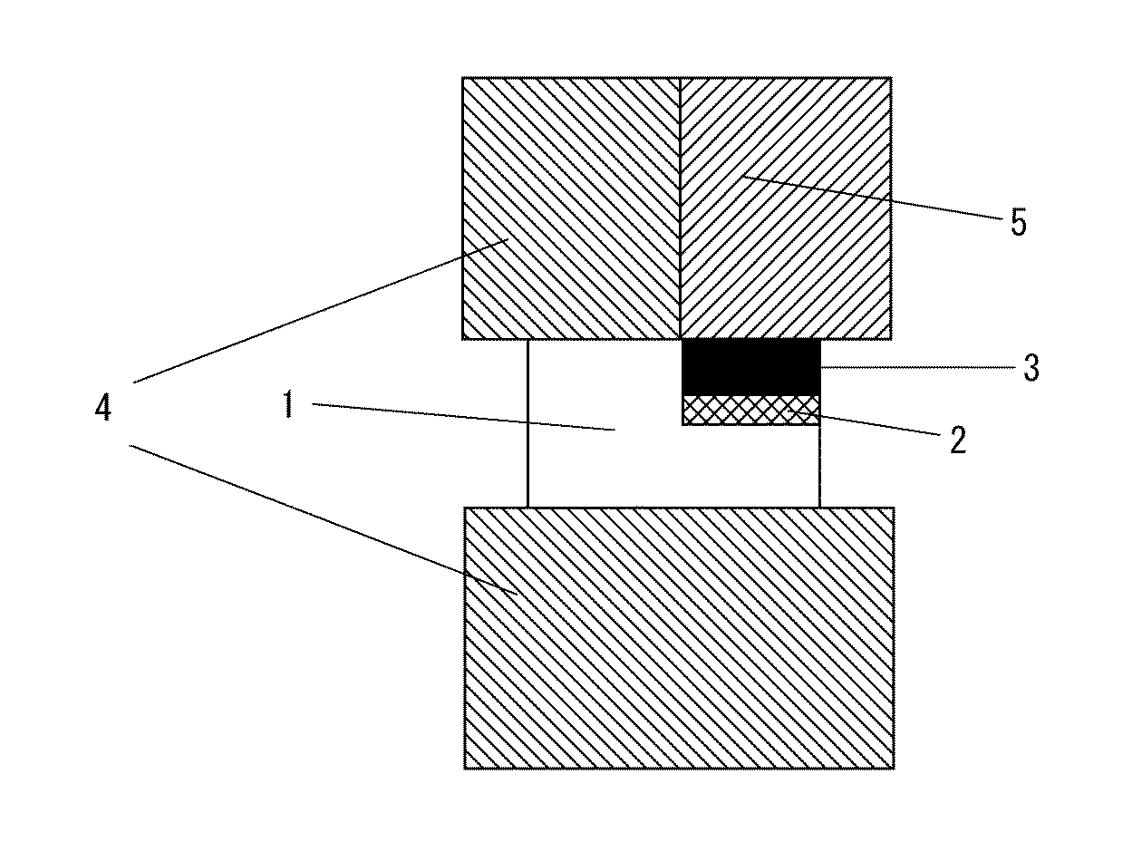
表1に示すように、0.1〜100MPaの加圧力の場合(実施例1〜5)には、従来のロウ付け品と同等の強度が得られていると共に、被接合材の割れが認められない。また、100〜200MPaの場合には、被接合材の組成によっては、割れが認められない。しかし、加圧力が極端に低い場合(比較例1)には、接合されず、200MPaを超える加圧を行った場合(比較例2)には、被接合材の組成によらず、接合層近傍の被接合材に割れが発生している。この結果、本発明において、好ましい加圧力は、0.1〜200MPaであることが確認できた。 As shown in Table 1, in the case of the applied pressure of 0.1 to 100 MPa (Examples 1 to 5), the same strength as that of the conventional brazed product is obtained, and cracking of the joined material is recognized. I can't. Moreover, in the case of 100-200 MPa, a crack is not recognized depending on the composition of the materials to be joined. However, when the applied pressure is extremely low (Comparative Example 1), it is not joined, and when a pressure exceeding 200 MPa is applied (Comparative Example 2), the vicinity of the joining layer regardless of the composition of the materials to be joined. Cracks have occurred in the materials to be joined. As a result, in the present invention, it was confirmed that a preferable pressing force was 0.1 to 200 MPa.
(実施例7)
次に、めっきの代わりに物理的蒸着法であるスパッタ法を用いて、厚さ10μmのTi−30wt%Co層(接合材)をバックメタルのあるcBN(第2の被接合材)に設け、サーメット台金(第1の被接合材)と接合を行った。この時、サーメット台金(第1の被接合材)としては、前記被接合材Aおよび被接合材Bを用い、接合条件は実施例3と同じとした。その結果、cBNとサーメットはTi−Co層を介して空隙なく接合されていることが確認できた。これは、接合中に液相を生成していたためと推測される。なお、その接合強度は、被接合材Aでは250MPa、被接合材Bでは255MPaであった。
(Example 7)
Next, using a sputtering method that is a physical vapor deposition method instead of plating, a Ti-30 wt% Co layer (bonding material) having a thickness of 10 μm is provided on the cBN (second bonding material) with the back metal, It joined with the cermet base metal (1st to-be-joined material). At this time, as the cermet base metal (first bonded material), the bonded material A and the bonded material B were used, and the bonding conditions were the same as those in Example 3. As a result, it was confirmed that cBN and cermet were joined without gaps through the Ti—Co layer. This is presumably because a liquid phase was generated during bonding. The bonding strength was 250 MPa for the material A to be bonded and 255 MPa for the material B to be bonded.
次に、第1の被接合材としてA、Bを用いた実施例3の各接合体および実施例7の各接合体の各々にダイヤモンド砥石を用いて研削加工を施し、その後、公知のCVD法により、1000℃のコーティング温度で、TiCNとアルミナを各2μmの厚さで被覆し、CVD膜の成長の状況を観察した。その結果、接合材がNiである実施例3の接合体では、第1の被接合材の種類に関係なく、CVD膜の異常成長が見られた。一方、接合材がNiでなくTi−Coである実施例7の接合体では、第1の被接合材の種類に関係なく、CVD膜の異常成長は見られなかった。 Next, each of the joined bodies in Example 3 and each joined body in Example 7 using A and B as the first material to be joined is ground using a diamond grindstone, and then a known CVD method is used. Then, TiCN and alumina were each coated at a thickness of 2 μm at a coating temperature of 1000 ° C., and the state of growth of the CVD film was observed. As a result, in the bonded body of Example 3 in which the bonding material was Ni, abnormal growth of the CVD film was observed regardless of the type of the first bonded material. On the other hand, in the bonded body of Example 7 in which the bonding material was not Ni but Ti—Co, abnormal growth of the CVD film was not seen regardless of the type of the first bonded material.
(実施例8)
次に、Ti粉末を溶媒で溶いた材料(接合材)を、サーメット台金(被接合材A:第1の被接合材)に塗布し、バックメタル無しcBNチップ(第2の被接合材)とセットし、実施例3と同一の通電条件で通電加圧接合を行った。この接合体の接合強度は200MPaであり、従来のロウ付け品と同等の強度を有していることを確認した。この接合部分には緻密な厚み40μmのTi層が観察され、Ti粉末が溶融あるいは焼結していることが確認できた。
(Example 8)
Next, a material (bonding material) obtained by dissolving Ti powder in a solvent is applied to a cermet base metal (bonded material A: first bonded material), and a back metal-free cBN chip (second bonded material). Then, energization and pressure bonding was performed under the same energization conditions as in Example 3. The joint strength of this joined body was 200 MPa, and it was confirmed that it had the same strength as a conventional brazed product. A dense Ti layer having a thickness of 40 μm was observed at the joined portion, and it was confirmed that the Ti powder was melted or sintered.
(実施例9)
次に、前記実施例8を基に、通電時間の短縮化を目的として、実施例8に示した条件のうち通電時間を変化させて接合条件を求めた。その結果、通電時間を実施例8における10秒から8秒にした場合、パルス電流値を実施例8に示した電流値(2000A)よりも200A大きい電流において良好な接合が可能であった。さらに通電時間を6秒とした場合、パルス電流をさらに200A大きくすることによって良好な接合が可能であった。
Example 9
Next, based on the Example 8, for the purpose of shortening the energization time, the joining condition was obtained by changing the energization time among the conditions shown in Example 8. As a result, when the energization time was changed from 10 seconds in Example 8 to 8 seconds, good joining was possible at a current greater by 200 A than the current value (2000 A) shown in Example 8. Further, when the energization time was 6 seconds, good bonding was possible by further increasing the pulse current by 200 A.
(実施例10)
次に、cBN(第2の被接合材)の背面も精度良く接合するため、2方向から加圧しながら接合を行った。これまでの例と同様、上下の電極で垂直方向の加圧を行うと共に、別途横から荷重を与えてcBNを水平方向に加圧できるようにした。なお、第1の被接合材としては、被接合材Aを用いた。実施例3に用いたと同じNiめっきを施したcBNを使用し、パルス電流3000A、パルスOn:Off比1:4、通電時間10秒として接合を行った。
(Example 10)
Next, in order to join the back surface of cBN (second material to be joined) with high accuracy, the joining was performed while applying pressure from two directions. As in the previous examples, the vertical pressure was applied with the upper and lower electrodes, and the load was applied separately from the side so that the cBN could be pressurized in the horizontal direction. In addition, the to-be-joined material A was used as a 1st to-be-joined material. Using the same Ni-plated cBN as used in Example 3, bonding was performed with a pulse current of 3000 A, a pulse On: Off ratio of 1: 4, and an energization time of 10 seconds.
その結果、cBNの底面のみならず背面も、Ni層を介してサーメット台金と接合されていた。この時の接合強度は280MPaあり、垂直方向のみ加圧する場合に比べ、より高い強度が得られた。 As a result, not only the bottom surface of cBN but also the back surface was bonded to the cermet base metal via the Ni layer. The bonding strength at this time was 280 MPa, and higher strength was obtained as compared with the case where pressure was applied only in the vertical direction.
(実施例11)
次に、通電加圧する電極の内、上部電極を分割し、サーメット台金(被接合材A:第1の被接合材)を加圧する電極とcBN(第2の被接合材)を加圧する電極の材質を変えた。これにより、電極に流れる電流が変化し、サーメット台金とcBNに流れる電流値も変化する。その結果として、それぞれの温度を極端に変えることができ、高温において劣化が懸念されるcBNの温度を下げることができる。
(Example 11)
Next, among the electrodes to be energized and pressurized, the upper electrode is divided, and an electrode for pressing the cermet base metal (bonded material A: first bonded material) and an electrode for pressing cBN (second bonded material) The material of was changed. Thereby, the electric current which flows into an electrode changes, and the electric current value which flows into a cermet base metal and cBN also changes. As a result, each temperature can be changed extremely, and the temperature of cBN in which deterioration is a concern at high temperatures can be lowered.
サーメット台金を通電加圧する電極を黒鉛とし、cBNを通電加圧する電極をhBNとした。hBNは電気的に絶縁材料であり、電流はほとんど流れない。cBNはめっき済みのものを使用した。パルス電流2000A、パルスOn:Off比1:1、パルス幅10ms、通電時間10秒、荷重0.98kNで実験を行ったところ、cBNが熱劣化せずに接合することができた。これは、cBNに電流がほとんど流れず、cBNそのものはジュール発熱せずに、サーメット台金が優先的に加熱することによって、cBNの温度を上げずに接合できたためと推測される。なお、接合強度は、170MPaであり、従来のロウ付け品と同等の強度を有していた。 The electrode for energizing and pressing the cermet base metal was graphite, and the electrode for energizing and pressing cBN was hBN. hBN is an electrically insulating material, and almost no current flows. The cBN used was plated. When an experiment was conducted with a pulse current of 2000 A, a pulse On: Off ratio of 1: 1, a pulse width of 10 ms, an energization time of 10 seconds, and a load of 0.98 kN, cBN could be joined without thermal degradation. This is presumably because almost no current flowed through the cBN, the cBN itself did not generate Joule heat, and the cermet base metal was preferentially heated so that it could be joined without raising the temperature of the cBN. The bonding strength was 170 MPa, which was equivalent to that of a conventional brazed product.
(実施例12)
上部電極を、分割されていない電極とした以外は、実施例11と同様にして、接合体を得た。得られた接合体の接合強度は、250MPaであり、従来のロウ付け品と同等の強度で実施例11における接合強度よりも高かった。しかし、得られた接合体のcBNには、一部亀裂が発生しており、熱による品質劣化が見られた。
(Example 12)
A joined body was obtained in the same manner as in Example 11 except that the upper electrode was an undivided electrode. The joint strength of the obtained joined body was 250 MPa, which was the same strength as the conventional brazed product and higher than the joint strength in Example 11. However, some cracks occurred in the cBN of the obtained bonded body, and quality degradation due to heat was observed.
実施例11および実施例12の結果より、cBN(第2の被接合体)への電力供給を制御して、サーメット(第1の被接合体)を優先的に加熱することにより、cBN(第2の被接合体)の熱劣化がない、接合強度の高い接合体を得ることができることが確認できた。 From the results of Example 11 and Example 12, by controlling the power supply to cBN (second bonded body) and preferentially heating the cermet (first bonded body), cBN (first bonded body) It was confirmed that a bonded body having a high bonding strength without thermal deterioration of the second bonded body) can be obtained.
(実施例13)
次に、実施例11に示した絶縁性のhBNの代わりに、cBN(第2の被接合材)を加圧する電極の材質を導電性を有するものとした。このとき、サーメット台金(第1の被接合材)を加圧する電極の電気伝導度より高い電気伝導度を有する材料を使用した。これにより、サーメット台金とcBNに流す電流を変えることができ、サーメット台金に流す電流はcBN近傍の台金を加熱し、cBNに流す電流は接合材を優先的に加熱できるようにした。
(Example 13)
Next, instead of the insulating hBN shown in Example 11, the material of the electrode that pressurizes cBN (second bonded material) is made conductive. At this time, the material which has electrical conductivity higher than the electrical conductivity of the electrode which pressurizes a cermet base metal (1st to-be-joined material) was used. As a result, the current flowing through the cermet base metal and the cBN can be changed. The current flowing through the cermet base metal heats the base metal near the cBN, and the current flowing through the cBN can preferentially heat the bonding material.
具体的にはサーメット台金には約2000A、cBNには約1000Aとし(電流は推定値)、通電加圧接合を行った。この時、サーメット台金のザグリ深さとcBN高さの差は0.15mmあり、分割電極とすることで、ギャップが大きくてもサーメット台金とcBNの両方に加圧することが可能であった。通電の結果、cBNを劣化させることなく、かつ接合を強固に行うことが可能であった。 Specifically, the cermet base metal was set to about 2000 A, and cBN was set to about 1000 A (current is an estimated value), and energization and pressure bonding was performed. At this time, the difference between the counterbore depth and cBN height of the cermet base metal was 0.15 mm, and by using divided electrodes, it was possible to pressurize both the cermet base metal and the cBN even if the gap was large. As a result of energization, it was possible to perform bonding firmly without deteriorating cBN.
1 第1の被接合材
2 接合材
3 第2の被接合材
4 電極
5 分割電極
DESCRIPTION OF
Claims (11)
前記第2の被接合材よりも前記第1の被接合材を集中的に通電加熱して、前記第1の被接合材を、前記第2の被接合材よりも優先的に発熱させて接合することを特徴とする接合体の接合方法。 A joining method of a joined body using a cermet sintered body as a first material to be joined and a cBN sintered body or a diamond sintered body as a second material to be joined, wherein the first and second materials are joined. lines by the welded material, is less than 1000 ° C. disposed therebetween and bonded by means of a bonding material which does not generate a liquid phase, said bonding energized heating under a pressure of 0.1MPa~200MPa of Yes ,
The second concentrated energized heating the first material to be joined than the welded material, wherein the first material to be joined, the second and preferentially by heating than the welded material joined bonding method of the bonded body, characterized in to Rukoto.
Priority Applications (1)
| Application Number | Priority Date | Filing Date | Title |
|---|---|---|---|
| JP2008093418A JP5225729B2 (en) | 2008-03-31 | 2008-03-31 | Joining method of joined body |
Applications Claiming Priority (1)
| Application Number | Priority Date | Filing Date | Title |
|---|---|---|---|
| JP2008093418A JP5225729B2 (en) | 2008-03-31 | 2008-03-31 | Joining method of joined body |
Publications (2)
| Publication Number | Publication Date |
|---|---|
| JP2009241236A JP2009241236A (en) | 2009-10-22 |
| JP5225729B2 true JP5225729B2 (en) | 2013-07-03 |
Family
ID=41303753
Family Applications (1)
| Application Number | Title | Priority Date | Filing Date |
|---|---|---|---|
| JP2008093418A Expired - Fee Related JP5225729B2 (en) | 2008-03-31 | 2008-03-31 | Joining method of joined body |
Country Status (1)
| Country | Link |
|---|---|
| JP (1) | JP5225729B2 (en) |
Families Citing this family (4)
| Publication number | Priority date | Publication date | Assignee | Title |
|---|---|---|---|---|
| US8920079B2 (en) | 2008-03-31 | 2014-12-30 | National Institute Of Advanced Industrial Science And Technology | Joined product |
| JP4647016B2 (en) * | 2009-05-27 | 2011-03-09 | 独立行政法人産業技術総合研究所 | Zygote |
| JP6694597B2 (en) | 2015-08-31 | 2020-05-20 | 三菱マテリアル株式会社 | Composite member and cutting tool |
| CN110465714A (en) * | 2019-07-24 | 2019-11-19 | 天津锦泰勤业精密电子有限公司 | A kind of welding method and Battery case of Battery case connector |
Family Cites Families (5)
| Publication number | Priority date | Publication date | Assignee | Title |
|---|---|---|---|---|
| JPS531609A (en) * | 1976-06-29 | 1978-01-09 | Chiaki Tamura | Method of uniting sintered alloy pieces |
| JPH07156003A (en) * | 1993-12-07 | 1995-06-20 | Sumitomo Electric Ind Ltd | Polycrystalline diamond tool and manufacturing method thereof |
| JP3509087B2 (en) * | 1995-02-08 | 2004-03-22 | 大同特殊鋼株式会社 | Titanium or titanium alloy joining method |
| JP2002036008A (en) * | 2000-07-24 | 2002-02-05 | Ngk Spark Plug Co Ltd | Indexable inserts and cutting tools |
| JP4854946B2 (en) * | 2004-09-30 | 2012-01-18 | 三菱マテリアル株式会社 | End mill material and end mill |
-
2008
- 2008-03-31 JP JP2008093418A patent/JP5225729B2/en not_active Expired - Fee Related
Also Published As
| Publication number | Publication date |
|---|---|
| JP2009241236A (en) | 2009-10-22 |
Similar Documents
| Publication | Publication Date | Title |
|---|---|---|
| JP5464442B2 (en) | Joining method | |
| JP4647016B2 (en) | Zygote | |
| CN103228393B (en) | Conjugate | |
| KR101344170B1 (en) | Cloth turning tool | |
| JP5225729B2 (en) | Joining method of joined body | |
| WO2015079183A4 (en) | Cutting insert, cutting tool comprising such an insert and methods for producing and repairing such a tool | |
| JP2008290130A (en) | Zygote | |
| JP2012111187A (en) | Binder | |
| JP2011025333A (en) | Joined body | |
| JP2012139695A (en) | Coated rotating tool | |
| JP5613293B2 (en) | Zygote | |
| JP7669296B2 (en) | Welding electrodes and methods of using same | |
| JP2012152827A (en) | Joined body | |
| JP6193651B2 (en) | Resistance welding electrode | |
| JPH0584363A (en) | Scissors and manufacture thereof | |
| JP2018048038A (en) | Laminated structure sintered superabrasive composite and method for producing the same | |
| JP2007276079A (en) | Cubic boron nitride based ceramic cutting tool with excellent brazing joint strength and high hardness machining, and Ag alloy brazing material used for cutting tool | |
| CN121423744A (en) | A method for regulating intermetallic compounds in molybdenum steel brazed joints based on transition elements | |
| JPS5938491A (en) | Composite sintered tool and production thereof | |
| JP2000006032A (en) | Manufacturing method of diamond polishing tool | |
| Zhang et al. | Research on dissimilar steel welding via spark plasma sintering | |
| JP2007118012A (en) | Vertical improvement welding method |
Legal Events
| Date | Code | Title | Description |
|---|---|---|---|
| A621 | Written request for application examination |
Free format text: JAPANESE INTERMEDIATE CODE: A621 Effective date: 20100727 |
|
| A521 | Request for written amendment filed |
Free format text: JAPANESE INTERMEDIATE CODE: A821 Effective date: 20100727 |
|
| A977 | Report on retrieval |
Free format text: JAPANESE INTERMEDIATE CODE: A971007 Effective date: 20120621 |
|
| A131 | Notification of reasons for refusal |
Free format text: JAPANESE INTERMEDIATE CODE: A131 Effective date: 20120723 |
|
| A521 | Request for written amendment filed |
Free format text: JAPANESE INTERMEDIATE CODE: A523 Effective date: 20120913 |
|
| A131 | Notification of reasons for refusal |
Free format text: JAPANESE INTERMEDIATE CODE: A131 Effective date: 20121105 |
|
| A521 | Request for written amendment filed |
Free format text: JAPANESE INTERMEDIATE CODE: A523 Effective date: 20121225 |
|
| TRDD | Decision of grant or rejection written | ||
| A01 | Written decision to grant a patent or to grant a registration (utility model) |
Free format text: JAPANESE INTERMEDIATE CODE: A01 Effective date: 20130212 |
|
| A61 | First payment of annual fees (during grant procedure) |
Free format text: JAPANESE INTERMEDIATE CODE: A61 Effective date: 20130313 |
|
| R150 | Certificate of patent or registration of utility model |
Ref document number: 5225729 Country of ref document: JP Free format text: JAPANESE INTERMEDIATE CODE: R150 Free format text: JAPANESE INTERMEDIATE CODE: R150 |
|
| FPAY | Renewal fee payment (event date is renewal date of database) |
Free format text: PAYMENT UNTIL: 20160322 Year of fee payment: 3 |
|
| S533 | Written request for registration of change of name |
Free format text: JAPANESE INTERMEDIATE CODE: R313533 |
|
| R350 | Written notification of registration of transfer |
Free format text: JAPANESE INTERMEDIATE CODE: R350 |
|
| R250 | Receipt of annual fees |
Free format text: JAPANESE INTERMEDIATE CODE: R250 |
|
| R250 | Receipt of annual fees |
Free format text: JAPANESE INTERMEDIATE CODE: R250 |
|
| R250 | Receipt of annual fees |
Free format text: JAPANESE INTERMEDIATE CODE: R250 |
|
| R250 | Receipt of annual fees |
Free format text: JAPANESE INTERMEDIATE CODE: R250 |
|
| R250 | Receipt of annual fees |
Free format text: JAPANESE INTERMEDIATE CODE: R250 |
|
| R250 | Receipt of annual fees |
Free format text: JAPANESE INTERMEDIATE CODE: R250 |
|
| R250 | Receipt of annual fees |
Free format text: JAPANESE INTERMEDIATE CODE: R250 |
|
| LAPS | Cancellation because of no payment of annual fees |