JP5222126B2 - Image processing method, image processing apparatus, and program - Google Patents
Image processing method, image processing apparatus, and program Download PDFInfo
- Publication number
- JP5222126B2 JP5222126B2 JP2008330381A JP2008330381A JP5222126B2 JP 5222126 B2 JP5222126 B2 JP 5222126B2 JP 2008330381 A JP2008330381 A JP 2008330381A JP 2008330381 A JP2008330381 A JP 2008330381A JP 5222126 B2 JP5222126 B2 JP 5222126B2
- Authority
- JP
- Japan
- Prior art keywords
- document
- image
- area
- determined
- candidate
- Prior art date
- Legal status (The legal status is an assumption and is not a legal conclusion. Google has not performed a legal analysis and makes no representation as to the accuracy of the status listed.)
- Expired - Fee Related
Links
Images


Classifications
-
- H—ELECTRICITY
- H04—ELECTRIC COMMUNICATION TECHNIQUE
- H04N—PICTORIAL COMMUNICATION, e.g. TELEVISION
- H04N1/00—Scanning, transmission or reproduction of documents or the like, e.g. facsimile transmission; Details thereof
- H04N1/00002—Diagnosis, testing or measuring; Detecting, analysing or monitoring not otherwise provided for
-
- G—PHYSICS
- G06—COMPUTING; CALCULATING OR COUNTING
- G06V—IMAGE OR VIDEO RECOGNITION OR UNDERSTANDING
- G06V10/00—Arrangements for image or video recognition or understanding
- G06V10/20—Image preprocessing
- G06V10/22—Image preprocessing by selection of a specific region containing or referencing a pattern; Locating or processing of specific regions to guide the detection or recognition
- G06V10/225—Image preprocessing by selection of a specific region containing or referencing a pattern; Locating or processing of specific regions to guide the detection or recognition based on a marking or identifier characterising the area
-
- H—ELECTRICITY
- H04—ELECTRIC COMMUNICATION TECHNIQUE
- H04N—PICTORIAL COMMUNICATION, e.g. TELEVISION
- H04N1/00—Scanning, transmission or reproduction of documents or the like, e.g. facsimile transmission; Details thereof
- H04N1/00002—Diagnosis, testing or measuring; Detecting, analysing or monitoring not otherwise provided for
- H04N1/00005—Diagnosis, testing or measuring; Detecting, analysing or monitoring not otherwise provided for relating to image data
-
- H—ELECTRICITY
- H04—ELECTRIC COMMUNICATION TECHNIQUE
- H04N—PICTORIAL COMMUNICATION, e.g. TELEVISION
- H04N1/00—Scanning, transmission or reproduction of documents or the like, e.g. facsimile transmission; Details thereof
- H04N1/00002—Diagnosis, testing or measuring; Detecting, analysing or monitoring not otherwise provided for
- H04N1/00026—Methods therefor
- H04N1/00037—Detecting, i.e. determining the occurrence of a predetermined state
-
- H—ELECTRICITY
- H04—ELECTRIC COMMUNICATION TECHNIQUE
- H04N—PICTORIAL COMMUNICATION, e.g. TELEVISION
- H04N1/00—Scanning, transmission or reproduction of documents or the like, e.g. facsimile transmission; Details thereof
- H04N1/00002—Diagnosis, testing or measuring; Detecting, analysing or monitoring not otherwise provided for
- H04N1/00026—Methods therefor
- H04N1/00039—Analysis, i.e. separating and studying components of a greater whole
-
- H—ELECTRICITY
- H04—ELECTRIC COMMUNICATION TECHNIQUE
- H04N—PICTORIAL COMMUNICATION, e.g. TELEVISION
- H04N1/00—Scanning, transmission or reproduction of documents or the like, e.g. facsimile transmission; Details thereof
- H04N1/00002—Diagnosis, testing or measuring; Detecting, analysing or monitoring not otherwise provided for
- H04N1/00026—Methods therefor
- H04N1/0005—Methods therefor in service, i.e. during normal operation
-
- H—ELECTRICITY
- H04—ELECTRIC COMMUNICATION TECHNIQUE
- H04N—PICTORIAL COMMUNICATION, e.g. TELEVISION
- H04N1/00—Scanning, transmission or reproduction of documents or the like, e.g. facsimile transmission; Details thereof
- H04N1/00002—Diagnosis, testing or measuring; Detecting, analysing or monitoring not otherwise provided for
- H04N1/00026—Methods therefor
- H04N1/00063—Methods therefor using at least a part of the apparatus itself, e.g. self-testing
-
- H—ELECTRICITY
- H04—ELECTRIC COMMUNICATION TECHNIQUE
- H04N—PICTORIAL COMMUNICATION, e.g. TELEVISION
- H04N1/00—Scanning, transmission or reproduction of documents or the like, e.g. facsimile transmission; Details thereof
- H04N1/00002—Diagnosis, testing or measuring; Detecting, analysing or monitoring not otherwise provided for
- H04N1/00071—Diagnosis, testing or measuring; Detecting, analysing or monitoring not otherwise provided for characterised by the action taken
- H04N1/00082—Adjusting or controlling
-
- H—ELECTRICITY
- H04—ELECTRIC COMMUNICATION TECHNIQUE
- H04N—PICTORIAL COMMUNICATION, e.g. TELEVISION
- H04N1/00—Scanning, transmission or reproduction of documents or the like, e.g. facsimile transmission; Details thereof
- H04N1/00127—Connection or combination of a still picture apparatus with another apparatus, e.g. for storage, processing or transmission of still picture signals or of information associated with a still picture
- H04N1/00326—Connection or combination of a still picture apparatus with another apparatus, e.g. for storage, processing or transmission of still picture signals or of information associated with a still picture with a data reading, recognizing or recording apparatus, e.g. with a bar-code apparatus
- H04N1/00328—Connection or combination of a still picture apparatus with another apparatus, e.g. for storage, processing or transmission of still picture signals or of information associated with a still picture with a data reading, recognizing or recording apparatus, e.g. with a bar-code apparatus with an apparatus processing optically-read information
- H04N1/00336—Connection or combination of a still picture apparatus with another apparatus, e.g. for storage, processing or transmission of still picture signals or of information associated with a still picture with a data reading, recognizing or recording apparatus, e.g. with a bar-code apparatus with an apparatus processing optically-read information with an apparatus performing pattern recognition, e.g. of a face or a geographic feature
-
- H—ELECTRICITY
- H04—ELECTRIC COMMUNICATION TECHNIQUE
- H04N—PICTORIAL COMMUNICATION, e.g. TELEVISION
- H04N1/00—Scanning, transmission or reproduction of documents or the like, e.g. facsimile transmission; Details thereof
- H04N1/00127—Connection or combination of a still picture apparatus with another apparatus, e.g. for storage, processing or transmission of still picture signals or of information associated with a still picture
- H04N1/00326—Connection or combination of a still picture apparatus with another apparatus, e.g. for storage, processing or transmission of still picture signals or of information associated with a still picture with a data reading, recognizing or recording apparatus, e.g. with a bar-code apparatus
Description
本発明は、画像読取装置の原稿台に置かれている原稿を読み取り、この読み取った画像を処理し、出力する画像処理装置に係り、特に、原稿台に置かれている複数の原稿を一括して読み取り、原稿領域の画像を出力する画像処理装置に関する。 The present invention relates to an image processing apparatus that reads a document placed on a document table of an image reading apparatus, processes the read image, and outputs the processed image. In particular, the present invention relates to a plurality of documents placed on a document table. The present invention relates to an image processing apparatus that reads and outputs an image of a document area.
近年、通信ネットワークの発達、コンピュータの高速化及び記憶媒体の大容量化に伴い、画像情報が頻繁に取り扱われている。特に、スキャナ等で取り込んだ画像情報を、より正確・高速に読み取りたいという要求が高まっている。 In recent years, with the development of communication networks, the speeding up of computers, and the increase in capacity of storage media, image information is frequently handled. In particular, there is an increasing demand for reading image information captured by a scanner or the like more accurately and at high speed.
従来、原稿台に置かれている原稿から、読み取るべき読取対象を抽出し、原稿位置、原稿サイズ等で表現される原稿領域を、自動的に決定する方法が知られている。このための第1の方法は、抽出した全ての読取対象に基づいて、原稿領域を決定する方法である(たとえば、特許文献1参照)。この第1の方法は、原稿が1枚のみ置かれていることが、予め分かっている場合に有効な方法である。 Conventionally, a method is known in which a reading target to be read is extracted from a document placed on a document table, and a document region expressed by a document position, a document size, and the like is automatically determined. The first method for this purpose is a method of determining a document area based on all extracted reading objects (see, for example, Patent Document 1). This first method is effective when it is known in advance that only one document is placed.
第2の方法は、複数の読取対象から、個々の読取対象を抽出し、この抽出された個々の読取対象に基づいて、原稿領域を決定する方法である(たとえば、特許文献2、3参照)。第2の方法は、原稿を1枚に限定しないことが前提であり、個々の読取対象について、1枚の原稿の領域を、それぞれ決定することができる。
全ての読取対象から原稿領域を決定する従来の第1の方法は、原稿が1枚であることを前提に処理するので、原稿台に複数の原稿が置かれている場合、適切な原稿領域を決定することができないという問題がある。 The first conventional method for determining the document area from all the reading targets is based on the assumption that there is only one document. Therefore, when a plurality of documents are placed on the document table, an appropriate document area is selected. There is a problem that it cannot be determined.
一方、上記従来の第2の方法は、複数の読取対象から、個々の読取対象を抽出し、この抽出された個々の読取対象に基づいて原稿領域を決定するので、適切な原稿領域を決定することができる。しかし、雑誌等、1つの原稿の内部に、写真等が配置されている場合、内部の写真を、独立した読取対象(1つの原稿)として抽出する可能性が残る。この結果、複数の読取対象から、個々の読取対象を抽出し、この抽出された個々の読取対象から原稿領域を決定する従来方法を用いると、内部の写真を、1つの独立した原稿領域として決定する。 On the other hand, in the second conventional method, individual reading objects are extracted from a plurality of reading objects, and an original area is determined based on the extracted individual reading objects, so an appropriate original area is determined. be able to. However, in the case where a photograph or the like is placed inside one original such as a magazine, there is a possibility that the internal photograph is extracted as an independent reading target (one original). As a result, using the conventional method of extracting individual reading objects from a plurality of reading objects and determining the document area from the extracted individual reading objects, the internal photo is determined as one independent document area. To do.
この原稿領域を決定する場合において精度が低下すると、ユーザ自身が置いた原稿に、適切な処理をユーザに選択させる方法が考えられる。しかし、初心者ユーザ等が置いた原稿について、どちらの処理が適切であるかを、上記初心者ユーザが判断できなければ、原稿領域を決定する場合における精度を向上させることができないという問題がある。 If accuracy is lowered in determining the document area, a method of allowing the user to select an appropriate process for the document placed by the user himself can be considered. However, if the novice user cannot determine which processing is appropriate for a document placed by a novice user or the like, there is a problem that accuracy in determining a document region cannot be improved.
また、「ユーザ自身が置いた原稿に、ユーザが適切な処理を選択する」という操作が増え、操作が煩雑であるという問題がある。この問題は、原稿を原稿台に置き、ユーザが「読み取りボタン」を押すと、原稿に応じて最適な読み取り領域の画像を得ることができるという機能を実現する場合の障害になるという問題がある。 In addition, there is a problem that the operation of “the user selects an appropriate process for the original placed by the user” increases and the operation is complicated. This problem has a problem that when a document is placed on a document table and the user presses a “reading button”, an obstacle in realizing a function of obtaining an image of an optimum reading area according to the document is caused. .
本発明は、原稿に対応する原稿領域を、当該原稿の読取画像から適切に特定することができる画像処理方法、画像処理装置及びプログラムを提供することを目的とする。
An object of the present invention is to provide an image processing method, an image processing apparatus, and a program that can appropriately specify a document area corresponding to a document from a read image of the document .
本発明の画像処理装置は、読取装置が原稿を読み取ることで得られた読取画像から、上記原稿に対応する原稿領域を特定するための画像処理装置において、上記読取画像を解析することにより、当該読取画像のうちの、上記原稿領域の候補である1または複数の候補領域を抽出する抽出手段と、上記抽出手段により複数の候補領域が抽出されたときに、当該複数の候補領域のそれぞれに対応する画像に基づき、当該複数の候補領域のうち、表を含む候補領域があるか判別する判別手段と、上記判別手段により表を含む候補領域があると判別された場合、上記複数の候補領域を含む領域を、1つの原稿に対応する上記原稿領域として特定し、上記判別手段により表を含む候補領域があると判別されなかった場合、当該複数の候補領域のそれぞれを、複数の原稿のそれぞれに対応する個別の上記原稿領域として特定する特定手段とを有することを特徴とする。The image processing apparatus of the present invention analyzes the read image in an image processing apparatus for specifying a document area corresponding to the document from a read image obtained by reading the document by the reading device. Extraction means for extracting one or a plurality of candidate areas that are candidates for the document area in the read image, and when a plurality of candidate areas are extracted by the extraction means, each of the plurality of candidate areas corresponds. And determining means for determining whether or not there is a candidate area including a table among the plurality of candidate areas, and when the determining means determines that there is a candidate area including a table, the plurality of candidate areas are When the area including the image is identified as the original area corresponding to one original and the determination unit does not determine that there is a candidate area including the table, each of the plurality of candidate areas , Characterized by having a specifying means for specifying as separate the document area corresponding to each of the plurality of documents.
また、本発明の画像処理方法は、読取装置が原稿を読み取ることで得られた読取画像から、上記原稿に対応する原稿領域を特定するための画像処理方法において、上記読取画像を解析することにより、当該読取画像のうちの、上記原稿領域の候補である1または複数の候補領域を抽出する抽出工程と、上記抽出工程において複数の候補領域が抽出されたときに、当該複数の候補領域のそれぞれに対応する画像に基づき、当該複数の候補領域のうち、表を含む候補領域があるか判別する判別工程と、上記判別工程において表を含む候補領域があると判別された場合、上記複数の候補領域を含む領域を、1つの原稿に対応する上記原稿領域として特定し、上記判別工程において表を含む候補領域があると判別されなかった場合、当該複数の候補領域のそれぞれを、複数の原稿のそれぞれに対応する個別の上記原稿領域として特定する特定工程とを有することを特徴とする。The image processing method of the present invention is an image processing method for specifying a document area corresponding to the document from a read image obtained by reading the document by a reading device, by analyzing the read image. An extraction step of extracting one or a plurality of candidate regions that are candidates for the document region in the read image, and when a plurality of candidate regions are extracted in the extraction step, each of the plurality of candidate regions A determination step of determining whether there is a candidate region including a table among the plurality of candidate regions, and a plurality of candidates when it is determined in the determination step that there is a candidate region including a table When an area including an area is specified as the original area corresponding to one original and it is not determined that there is a candidate area including a table in the determination step, the plurality of candidate areas Respectively, and having a specifying step of specifying as separate the document area corresponding to each of the plurality of document.
本発明によれば、原稿に対応する原稿領域を、当該原稿の読取画像から適切に特定することができる。According to the present invention, a document area corresponding to a document can be appropriately specified from a read image of the document.
発明を実施するための最良の形態は、次の実施例である。 The best mode for carrying out the invention is the following embodiment.
図1は、本発明の実施例1である画像読取装置R1を示す断面図である。
FIG. 1 is a cross-sectional view illustrating an image reading apparatus R1 that is
画像読取装置R1は、スキャナ10を有し、読取原稿D1が載置される。スキャナ10は、不図示のインタフェースケーブルによって、ホストコンピュータ(以下、「ホストPC」という)に接続される。
The image reading device R1 includes a
画像読取装置R1は、プーリP1、P2と、原稿台ガラスG1と、ギア列11と、ガイドレール12と、白色基準板13と、圧板14と、パルスモータ17と、無端ベルト18と、光学ユニット30と、電気基板40とを有する。
The image reading device R1 includes pulleys P1 and P2, an original table glass G1, a
白色基準板13の中に、黒マーク13bが設けられ、スキャナ10は、この黒マーク13bを基準にし、読み取りエリアを決め、画像を読み取る。
A
光学ユニット30、パルスモータ17は、それぞれ、不図示のケーブルによって、電気的に接続されている。また、光学ユニット30は、圧板14に載置され、ガイドレール12に沿って摺動可能であり、圧板14は、無端ベルト18に固着されている。
The
光学ユニット30は、反射原稿用光源15と、複数の反射ミラーM1、M2、M3と、結像レンズ19と、撮像手段であるラインセンサ20とによって構成されている。
The
次に、スキャナ10における反射原稿画像の読み取り動作について説明する。
Next, the operation of reading the reflected original image in the
ホストPCが読み取り命令コマンドを発生すると、スキャナ10が読み取り動作を開始する。スキャナ10は、光学ユニット30の反射原稿用光源15を点灯し、読取原稿D1からの反射光を、複数の反射ミラーM1、M2、M3が反射し、結像レンズ19を介して、ラインセンサ20に結像することによって、主走査方向1ライン分の画像を読み取る。
When the host PC generates a reading command, the
ギア列11を介して、パルスモータ17の動力によって、プーリP1を回転させ、無端ベルト18を駆動する。これによって、圧板14に固着されている光学ユニット30は、矢印Xで示す副走査方向に、ガイドレール上を移動する。
The pulley P1 is rotated by the power of the
スキャナ10は、光学ユニット30を、副走査方向に移動しつつ、上記主走査方向のライン画像の読み取りを繰り返し、図1に点線で示す位置まで読み取り動作をしながら、光学ユニット30を移動し、原稿台ガラスG1の全面をスキャンする。
The
ただし、ホストPCからの読み取りコマンドの内容に応じて、原稿台ガラスG1上の原稿の部分画像を読むことができる。この場合、ホストPCが指定する読み取り画像領域に対して、主走査方向には、センサ出力のうちで採用する画素領域を、電気基板40上の上記制御部が規定することによって、原稿台ガラスG1上の読取原稿D1の部分画像を読むことができる。
However, the partial image of the original on the platen glass G1 can be read according to the content of the read command from the host PC. In this case, with respect to the read image area designated by the host PC, in the main scanning direction, the pixel area used in the sensor output is defined by the control unit on the
また、副走査方向には、光学ユニット30の移動領域を、電気基板40上の上記制御部が規定することによって、原稿台ガラスG1上の読取原稿D1の部分画像を読む。副走査方向に、光学ユニット30を移動させる場合、ホストPCが指定する画像読み取りの解像度設定に応じて、システムコントローラ41が速度を選択し、画像を読み取る。
Further, in the sub-scanning direction, the moving unit of the
なお、スキャナ10は、原稿台画像から複数の原稿画像の領域を抽出することが可能なマルチクロップスキャン機能を有し、ホストPC又はスキャナ10自身の制御によって、原稿台ガラスG1上に配置されている複数の読取原稿D1を、自動的に順に読み取る。
The
圧板14上に、オペレーションパネルを設置し、このオペレーションパネルに、液晶画面とボタンとを設け、ユーザが、マルチクロップのパラメータをスキャナ10に入力し、読み取りの開始等の操作を行う。
An operation panel is installed on the pressure plate 14, a liquid crystal screen and buttons are provided on the operation panel, and a user inputs multi-crop parameters to the
図2は、実施例1において、スキャナ10の構成を示すブロック図である。
FIG. 2 is a block diagram illustrating the configuration of the
スキャナ10は、光学ユニット30と、電気基板40と、パルスモータ17と、透過原稿用光源と、モータ駆動回路MD1と有する。
The
光学ユニット30は、光源点灯回路31を有し、光源点灯回路31は、反射原稿用光源15を点灯する回路であり、この中に、反射原稿用光源15の光量検知を行う検知部が含まれている。反射原稿用光源15に、冷陰極管を用いた場合、いわゆるインバータ回路を構成する。
The
電気基板40は、システムコントローラ41と、アナログゲイン調整器42R、42G、42Bと、A/D変換器43と、画像処理部44と、ラインバッファ45と、インタフェース部46とを有する。また、電気基板40は、オフセットRAM47と、ガンマRAM48と、CPUバス49とを有する。
The
アナログゲイン調整器42R、42G、42Bは、ラインセンサ20から出力されたアナログ画像信号を可変増幅する。A/D変換器43は、アナログゲイン調整器42R、42G、42Bが出力したアナログ画像信号をデジタル画像信号に変換する。画像処理部44は、デジタル信号化された画像信号について、オフセット補正、シェーディング補正、デジタルゲイン調整、カラーバランス調整、マスキング、主・副走査方向の解像度変換、画像圧縮等の画像処理を行う。
The
ラインバッファ45は、画像データを一時的に記憶し、汎用のランダムアクセスメモリを有する。インタフェース部46は、ホストPC50と通信し、USBインタフェースによって構成されている。インタフェース部46として、IEEE1394等、別のインタフェースを採用するようにしてもよい。
The
オフセットRAM47は、画像処理を行う際のワーキングエリアとして用いるRAMであり、RGB用ラインセンサが、それぞれ所定のオフセットを持ち、ラインセンサ20に、平行に配置されている。このために、オフセットRAM47は、RGBラインセンサ間オフセットの補正用として用いられている。また、オフセットRAM47は、シェーディング補正等、各種データの一時記憶を行う。ここでは、汎用のランダムアクセスメモリで実現している。ガンマRAM48は、ガンマカーブを記憶し、ガンマ補正を行うためのRAMである。
The offset
システムコントローラ41は、フィルムスキャナ全体のシーケンスを記憶しているシステムコントローラであり、ホストPC50からの命令に従って、各種制御を行う。
The system controller 41 is a system controller that stores the entire sequence of the film scanner, and performs various controls in accordance with instructions from the
CPUバス49は、システムコントローラ41と、画像処理部44と、ラインバッファ45と、インタフェース部46と、オフセットRAM47と、ガンマRAM48とを接続するバスであり、アドレスバスとデータバスとを有する。
The
モータ駆動回路MD1は、パルスモータ17用のモータ駆動回路であり、スキャナ10のシステム制御手段であるシステムコントローラ41からの信号によって、パルスモータ17の励磁切替え信号を出力する。
The motor drive circuit MD1 is a motor drive circuit for the
次に、実施例1において、スキャナ10を制御するホストPC50の概略構成について、説明する。
Next, a schematic configuration of the
図3は、実施例1において、スキャナ10を制御するホストPC50の概略構成を示す図である。
FIG. 3 is a diagram illustrating a schematic configuration of the
ホストPC50は、中央処理装置51と、ROM52と、RAM53と、ディスク装置54と、バス55と、I/F56、57と、外部記憶装置58とを有する。
The
ROM52は、図4に示すフローチャートの動作を実現するプログラムを保持する。RAM53は、上記プログラムの動作に必要な記憶領域とワークエリアとを提供する。中央処理装置51は、ROM52に保持されているプログラムに従って処理を行う。
The
バス55は、上記各構成を接続し、各構成間におけるデータの授受を可能とする。I/F56は、スキャナ10との通信を行うI/Fであり、スキャナ10のインタフェース部46と同様に、USBインタフェースで実現しているが、IEEE1394等、別のインタフェースを採用するようにしてもよい。
The
I/F57は、マウスやキーボード等の入力部61と接続する。また、外部記憶装置58は、フロッピー(登録商標)ディスクやCD−ROM等、外部記憶媒体を駆動するための記憶装置である。また、I/F57は、上記のように、ROM52に制御プログラムを予め保持する代わりに、外部記憶媒体に記憶されている場合に、それを読み出してダウンロードするという効果をする。なお、図示しないネットワークコネクタを介して、ネットワーク経由で、制御プログラムをダウンロードするようにしてもよい。
The I /
なお、スキャナ10は、読み取るべき読取対象が記載されている原稿であって、原稿台に載置されている原稿を読み取り、原稿台画像を得る読取手段の例である。
Note that the
中央処理装置51は、上記原稿台画像に含まれる複数の画像領域を抽出する画像抽出手段の例である。
The
中央処理装置51は、上記抽出された複数の画像領域のそれぞれについて、特定の原稿特徴を具備するか否かを判別する判別手段の例である。また、中央処理装置51は、上記複数の画像領域の少なくとも1つが上記原稿特徴を具備する場合には、上記複数の画像領域の全てを包含する矩形領域を原稿領域であると判断する判断手段の例である。なお、上記矩形領域は、図7に示す抽出結果81、82である。また、中央処理装置51は、上記複数の画像領域のいずれもが上記特定の原稿特徴を具備しない場合には、上記複数の画像領域それぞれが原稿領域であると判断する判断手段の例である。
The
また、中央処理装置51は、上記複数の画像領域を二値化する手段の例であり、二値化された上記複数の画像領域それぞれに対し、画像領域内に存在する隣接する画素同士に同じラベルを設定するラベル設定手段の例である。中央処理装置51は、ラベル毎に水平方向及び垂直方向それぞれのラベルの出現回数をカウントするカウント手段の例である。この場合、上記カウントの結果のピーク値が第1の閾値以上であり、かつピークの幅が第2の閾値以下のピークが水平方向及び垂直方向それぞれに3回以上出現した場合に表であると判断する。
Further, the
中央処理装置51は、ラベル毎に水平方向及び垂直方向それぞれのヒストグラムを算出する算出手段の例である。この場合、上記ラベル毎のヒストグラムのピーク値が第1の閾値以上であり、かつピークの幅が第2の閾値以下のピークが水平方向及び垂直方向それぞれに3回以上出現した場合に表であると判断する。また、上記第1の閾値は、線分の長さであり、上記第2の閾値は、線分の太さを決定するための閾値である。
The
次に、実施例1において、ホストPC50がスキャナ10を介して行う読み取り動作について、説明する。
Next, a reading operation performed by the
図4は、実施例1において、ホストPC50がスキャナ10を介して行う読み取り動作を示すフローチャートである。
FIG. 4 is a flowchart illustrating a reading operation performed by the
ステップS1で、スキャナは原稿台上に載置された読取原稿D1を含む原稿台全面の画像を読み取る。読み取る場合における画像の解像度は、仮のものであってもよく、ユーザ所望の解像度であってもよい。 In step S1, the scanner reads an image on the entire surface of the document table including the read document D1 placed on the document table. The resolution of the image in the case of reading may be temporary or may be a resolution desired by the user.
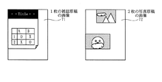
図5は、原稿台に雑誌原稿を1枚載置して読み取った際の原稿台画像71と、原稿台に2枚の写真原稿を載置して読み取った際の原稿台画像72とを示す図である。
FIG. 5 shows a
次にステップS2で、原稿台全面の画像から、原稿領域として読み取るべき読取対象となる画像領域を抽出する。詳細な抽出方法は別途図9を用いて説明する。 In step S2, an image area to be read is extracted as an original area from the image on the entire surface of the original platen. A detailed extraction method will be separately described with reference to FIG.
ステップS3で、読取原稿D1が1枚である場合と仮定して、抽出された全ての読取対象について、原稿領域を決定する。この原稿領域を決定する詳細な方法を、後述の図10に示すフローチャートを用いて別途説明する。 In step S3, assuming that there is one read original D1, original areas are determined for all of the extracted reading targets. A detailed method for determining the document area will be separately described with reference to a flowchart shown in FIG.
図7は、ステップS3で決定された原稿領域であって、原稿を1枚置いたときに得られる抽出結果81と、原稿を複数枚置いたときに得られる抽出結果82とを示す図である。 FIG. 7 is a diagram showing an extraction result 81 obtained when one original is placed, and an extraction result 82 obtained when a plurality of originals are placed, which are the document areas determined in step S3. .
図7において、ステップS3で決定された原稿領域を示す81の点線部は、原稿台に雑誌原稿を1枚載置して読み取った際の原稿台画像から得られる抽出結果を示す。また、82の点線部は、原稿台に2枚の写真原稿を載置して読み取った際の画像から得られる抽出結果を示す。2枚の写真原稿の画像領域を包含する最小の矩形領域が抽出結果である。 In FIG. 7, 81 dotted lines indicating the document area determined in step S <b> 3 indicate extraction results obtained from the document table image when one magazine document is placed on the document table and read. A dotted line 82 indicates an extraction result obtained from an image when two photographic originals are placed and read on the original table. The minimum rectangular area including the image areas of the two photo originals is the extraction result.
ここで得られた領域を、「1枚原稿領域」と呼ぶ。 The area obtained here is referred to as “one original area”.
次にステップS4で、抽出された読取対象となった画像領域の個数を数える。この抽出された読取対象として、ステップS2で得られた抽出結果を用いてもよく、またステップS2で使用した抽出方法を用いて、抽出するための設定を変えて再度抽出処理を行った抽出結果から得るようにしてもよい。 Next, in step S4, the number of image regions that have been extracted and read is counted. As the extracted reading object, the extraction result obtained in step S2 may be used, or the extraction result obtained by performing extraction processing again by changing the setting for extraction using the extraction method used in step S2. You may make it obtain from.
読取対象の個数を数える場合、ラベリングの方法がある。まず、カウンタを0に初期化し、画像を走査し、読取対象となる画素を探す。この読取対象となる画素に、カウント値が設定されていなければ、現在のカウント値0とラベル(たとえばA)とを設定する。なお、カウンタを0に初期化するので、カウント値は、0から始まり、カウント値を加算するので、カウント値は、1づつ増える。そして、隣接する読取対象となる画素にも、同じカウント値0とラベルA(値A)を設定する。新しくカウント値とラベルが設定された画素に隣接する画素についても、同じカウント値0とラベルA(値A)を設定する。隣接する読取対象を構成する画素で、カウント値とラベルが設定されていない画素がなくなると、カウント値を加算し、1にインクリメントし、ラベルの値も更新する。すなわち、上下左右に隣接した画素には、同じカウント値とラベルとが設定される。さらに画像を走査し、読取対象となる画像領域を探し、画像領域があれば、カウント値を加算し、新たなラベルを設定する。最後の画素までの走査が終了した時点のカウント値Nに1を加算した数が、抽出された読取対象となる画像領域の個数となる。
There is a labeling method for counting the number of objects to be read. First, the counter is initialized to 0, the image is scanned, and a pixel to be read is searched. If no count value is set for the pixel to be read, the
次に、ステップS5では、読取原稿D1が複数枚である場合を仮定し、抽出された複数の画像領域それぞれを原稿領域として決定する。このときに、写真が傾いて置かれた場合を想定し、原稿領域を傾けて、原稿領域を決定するようにしてもよい。 Next, in step S5, assuming that there are a plurality of read originals D1, each of the extracted image areas is determined as an original area. At this time, assuming that the photograph is placed at an angle, the document area may be determined by tilting the document area.
また、原稿台に置かれる原稿は、A4原稿や、L判写真など、ある一定の縦横比率以下の原稿を想定しており、極端に細長い原稿は、誤検知である可能性が考えられる。また、L判写真などは、重なって置かれた場合は、重なった個所の画像データを得ることが出来ないので、離して置かれる。この2つの条件を加味し、矩形の縦横比率が一定以上である場合や、矩形同士が接触している場合は、決定した原稿領域が正しくないとして、除外してもよい。 Further, the document placed on the document table is assumed to be an A4 document or a document having a certain aspect ratio, such as an L size photograph, and an extremely long document may be erroneously detected. In addition, when the L-size photos are placed in an overlapping manner, the image data of the overlapping portion cannot be obtained, so they are placed apart. Considering these two conditions, when the aspect ratio of the rectangle is a certain value or when the rectangles are in contact with each other, the determined document area may be excluded as being incorrect.
この詳細な決定方法は、図10に示すフローチャートを用いて、別途説明する。 This detailed determination method will be described separately using the flowchart shown in FIG.
図8は、ステップS5で決定された原稿領域であって、原稿を1枚置いたときに得られた抽出結果83と、原稿を複数枚置いたときに得られた抽出結果84とを示す図である。 FIG. 8 is a view showing the original region determined in step S5, and an extraction result 83 obtained when one original is placed and an extraction result 84 obtained when a plurality of originals are placed. It is.
図6に示す抽出画像73において、原稿の下辺、右辺が抽出されているが、図8の抽出結果83には反映されていない。これは、矩形の縦横比率や、矩形同士の接触、画像領域の大きさ等の条件から外れているので、抽出結果83からは外されたからである。 In the extracted image 73 shown in FIG. 6, the lower and right sides of the document are extracted, but are not reflected in the extraction result 83 of FIG. This is because it is excluded from the extraction result 83 because it is out of conditions such as the aspect ratio of the rectangle, the contact between the rectangles, and the size of the image area.
また、図8の抽出結果84において、ステップS5で得られた結果は、原稿を複数枚置いたときの画像には適切に処理されていることが分かる。ただし、この結果は、ステップS2の抽出結果に依存し、抽出結果によっては正しく処理できることもある。実施例1では、正しく処理できなかった場合を想定する。 Further, in the extraction result 84 of FIG. 8, it can be seen that the result obtained in step S5 is appropriately processed for the image when a plurality of documents are placed. However, this result depends on the extraction result in step S2, and may be processed correctly depending on the extraction result. In the first embodiment, it is assumed that the processing cannot be performed correctly.
ここで得られる複数の画像領域を、以下「複数枚原稿領域群」と呼ぶ。 The plurality of image areas obtained here will be hereinafter referred to as a “multiple document area group”.
ステップS6で、カウントされた全ての読取対象となった画像領域について、原稿領域が決定されたら、ステップS7へ進む。 In step S6, when the document area is determined for all the counted image areas to be read, the process proceeds to step S7.
ステップS7以降では、ステップS5で決定された複数枚原稿領域群の内部を判定し、原稿を複数置いたときの領域群であるかどうかを判定する。たとえば、ステップS2の読取対象抽出処理で、下地が白い原稿を置いた場合、白い下地はすなわち原稿領域として抽出されるべきである。しかし、原稿を押さえるための圧板14の原稿台ガラスG1に接する面の色が白い場合、原稿と圧板14との境界が検出されず、誤判定することがある。この誤判定結果とステップS5に示す決定処理とによって、読取対象の内部の領域が原稿領域であるにも関わらず「複数枚原稿領域群」であると決定してしまうことがある。この場合、ステップS2の読取対象抽出処理において抽出された結果が矩形であれば、誤判定結果となりやすい。なぜならば、ステップS5で領域を決定するが、このときに、縦横比率が一定以上の領域や、領域同士が接触している領域は除外される。ステップS5で決定された領域が矩形である場合、写真の場合も矩形になるので、ステップS5の除外条件には該当せず領域として決定される。このため、矩形領域が誤判定されやすくなる。 In step S7 and subsequent steps, the inside of the plurality of document area groups determined in step S5 is determined, and it is determined whether the area group is when a plurality of documents are placed. For example, when a document with a white background is placed in the reading target extraction process in step S2, the white background should be extracted as a document area. However, if the color of the surface of the pressure plate 14 that presses the document in contact with the platen glass G1 is white, the boundary between the document and the pressure plate 14 is not detected, and an erroneous determination may occur. The erroneous determination result and the determination process shown in step S5 may determine that the internal area to be read is a “multiple original area group” even though it is an original area. In this case, if the result extracted in the reading target extraction process in step S2 is a rectangle, an erroneous determination result is likely. This is because the area is determined in step S5, but at this time, the area having a certain aspect ratio or a region where the areas are in contact with each other is excluded. If the area determined in step S5 is a rectangle, the photograph is also a rectangle, so the area is determined not to meet the exclusion condition in step S5. For this reason, the rectangular area is likely to be erroneously determined.
たとえば、雑誌原稿中に現れる表は、矩形であるので、誤判定されやすい。そこで、読取対象として、表のみが原稿台に置かれることは無いと仮定し、個々の複数枚原稿領域群が表であるかどうかを検知することによって、ステップS5で決定された読み取り領域群が、誤判定結果であるかどうかを判定する。 For example, since a table appearing in a magazine manuscript is rectangular, it is likely to be erroneously determined. Therefore, it is assumed that only a table is not placed on the document table as a reading target, and the reading region group determined in step S5 is detected by detecting whether each of the plurality of document region groups is a table. It is determined whether or not the result is an erroneous determination result.
ステップS7において、個々の複数原稿領域群が表であるかどうかを判定する。個々の複数原稿領域群が表であるかどうかについての詳細な判定方法は、図11に示すフローチャートを用いて別途説明する。 In step S7, it is determined whether each of the plurality of document area groups is a table. A detailed determination method as to whether or not each of the plurality of document area groups is a table will be separately described with reference to the flowchart shown in FIG.
ステップS8において、ステップS7の判定結果が表であると判定されたら、ステップS9へ進む。ステップS7の判定結果が表であると判定されなければ、ステップS10へ進む。 If it is determined in step S8 that the determination result in step S7 is a table, the process proceeds to step S9. If it is not determined that the determination result of step S7 is a table, the process proceeds to step S10.
ステップS9では、ステップS3で決定された1枚原稿領域を、原稿領域の画像であると決定する。 In step S9, the single document area determined in step S3 is determined to be an image of the document area.
ステップS10では、ステップS5で決定された複数枚原稿領域群のそれぞれの画像領域を、原稿領域の画像であると決定する。 In step S10, each image area of the plurality of document area groups determined in step S5 is determined to be an image of the document area.
特に図示しないが、以降は、ステップS9またはステップS10で決定された原稿領域に基づいて、画像処理することができる。ステップS1で読み取られた画像の解像度が仮の物であれば、ステップS9またはステップS10で決定された原稿領域を、所望の解像度で読み取るようにしてもよい。ステップS9またはステップS10で得られた原稿領域が斜行していれば、斜行を補正するために、画像を回転するようにしてもよい。 Although not particularly shown, image processing can be performed thereafter based on the document area determined in step S9 or step S10. If the resolution of the image read in step S1 is temporary, the original area determined in step S9 or step S10 may be read with a desired resolution. If the document area obtained in step S9 or step S10 is skewed, the image may be rotated to correct skewing.
図9は、実施例1において、読み取るべき読取対象を抽出する動作(ステップS2)を示すフローチャートである。 FIG. 9 is a flowchart illustrating an operation (step S2) of extracting a reading target to be read in the first embodiment.
ステップS21で、画像を二値化するための閾値を決定する。この閾値は、後述するステップS26の比較方法に依存して最適な値が変わる。閾値を簡単に決定するには、固定の値を予め決めておけばよい。 In step S21, a threshold value for binarizing the image is determined. This threshold value varies depending on the comparison method in step S26 described later. In order to easily determine the threshold value, a fixed value may be determined in advance.
ステップS22で、ある1画素の値を取得する。画像から、読み取るべき読取対象を抽出するために、全ての画素に対して処理を行わなければならないが、ステップS22で1画素毎に処理することができる。通常は、X座標、Y座標を用いて、ある1画素の位置を特定する。処理開始時には、X座標、Y座標を初期値(一般的には0)で初期化し、1画素処理する毎に、X座標、Y座標を変化させ、全画素を走査する。 In step S22, the value of one pixel is acquired. In order to extract a reading target to be read from the image, it is necessary to perform processing for all the pixels. However, in step S22, the processing can be performed for each pixel. Usually, the position of a certain pixel is specified using the X coordinate and the Y coordinate. At the start of processing, the X and Y coordinates are initialized with initial values (generally 0), and every time one pixel is processed, the X and Y coordinates are changed to scan all pixels.
ステップS23では、ステップS22で取得した画素値の色空間を変換する。一般的に、ラインセンサ20の特性・カラーフィルタや、反射原稿用光源15によって、スキャナ10毎の色空間が異なる。デバイス非依存の色空間にすれば、スキャナ10に依存せずに、読取対象を抽出することができる可能性があるので、ステップS23で色空間を変換する。スキャナ10に依存したパラメータを調整し、ステップS21の処理における閾値を決定する場合、このステップS23の処理を省くことができる。
In step S23, the color space of the pixel value acquired in step S22 is converted. Generally, the color space for each
ステップS24では、ステップS23で得られた値を、スカラー値に変換する。カラー画像を入力する場合、RGB三色値を持っている。このRGB三色値(ベクトル値)と、閾値(スカラー値)とを比較するために、RGB三色値をスカラー値に変換する。 In step S24, the value obtained in step S23 is converted into a scalar value. When inputting a color image, it has RGB three-color values. In order to compare the RGB three-color value (vector value) with a threshold value (scalar value), the RGB three-color value is converted into a scalar value.
RGB三色値を、スカラー値に変換する場合、どれか1色のみを取り出す方法でもよく、RGB三色値に適当な重み付け平均をとり、輝度値を求める方法でもよく、RGB三色値から彩度を計算する方法でもよい。ただし、入力画像がグレースケール等、1色である場合、上記処理を必要としないので、ステップS24の処理を省くことができる。 When converting RGB tricolor values to scalar values, either one of the colors may be taken out, or an appropriate weighted average may be taken for the RGB tricolor values to obtain a luminance value. A method of calculating the degree may be used. However, when the input image is a single color such as a gray scale, the above process is not required, and therefore the process of step S24 can be omitted.
ステップS25では、ステップS24で得られた値から、n次微分や差分を計算する。画像から読取対象を抽出する処理において、原稿台に置いた読取原稿D1と、それ以外の境界とを抽出することによって、その後の原稿領域を精度よく決定することが容易になる可能性がある。この原稿台に置いた読取原稿D1の境界を抽出する目的で、n次微分や差分を計算する。この処理は、ステップS24で得られた値の特性に依存するので、必要がなければ、ステップS25の処理を省くことができる。 In step S25, an nth-order differentiation and a difference are calculated from the values obtained in step S24. In the process of extracting the reading target from the image, it may be easy to accurately determine the subsequent document area by extracting the read document D1 placed on the document table and the other boundary. In order to extract the boundary of the read original D1 placed on the original table, an nth-order differential and a difference are calculated. Since this process depends on the characteristic of the value obtained in step S24, the process in step S25 can be omitted if not necessary.
ステップS26では、ステップS25で得られた値と、ステップS21で決定した閾値とを比較し、閾値未満であれば、読取対象でないと判断し、閾値以上であれば、読取対象であると判断する。ただし、ステップS23からステップS25で求めた値によっては、この関係が逆転し、閾値未満であれば、読取対象であると判断し、閾値以上であれば、読取対象でないと判断するようにしてもよい。この関係を予め決めておく。たとえば、輝度値で判断する場合、閾値未満であれば、読取対象であると判断し、彩度で判断する場合、閾値以上であれば、読取対象であると判断するようにしてもよい。 In step S26, the value obtained in step S25 is compared with the threshold value determined in step S21, and if it is less than the threshold value, it is determined that it is not a reading object, and if it is equal to or more than the threshold value, it is determined that it is a reading object. . However, depending on the values obtained in step S23 to step S25, this relationship is reversed, and if it is less than the threshold value, it is determined that it is a reading target, and if it is equal to or more than the threshold value, it is determined that it is not a reading target. Good. This relationship is determined in advance. For example, when judging by the luminance value, if it is less than the threshold value, it may be judged as a reading target, and when judging by the saturation, if it is equal to or more than the threshold value, it may be judged as a reading target.
ステップS27では、ステップS26の結果を保存する。ステップS26の結果は、読取対象であるか、読取対象ではないかの2種類しかないので、0を読取対象、1を読取対象でない等のように、符号化して保存する。 In step S27, the result of step S26 is stored. Since there are only two types of results in step S26, that is, whether it is a reading target or a reading target, 0 is encoded as a reading target, 1 is not a reading target, and the like.
ステップS28で、全ての画素がステップS27で処理されたかどうかを調べ、全て処理されていれば、終了する。 In step S28, it is checked whether all the pixels have been processed in step S27. If all the pixels have been processed, the process ends.
実施例1において、ステップS21における閾値の決定に、ステップS25の結果が必要な場合があり、隣接する画素について、スカラー値への変換(ステップS24)の値を、ステップS25の計算で必要とする場合がある。このために、図9に示すフローチャートの処理順を、必要によって入れ替えるようにしてもよい。 In the first embodiment, the determination of the threshold value in step S21 may require the result of step S25, and the value of conversion to a scalar value (step S24) is required for calculation of step S25 for adjacent pixels. There is a case. For this purpose, the processing order of the flowchart shown in FIG. 9 may be changed as necessary.
実施例1では、図9に示すフローチャートを1回のみ実行するが、場合によっては、複数回実行するようにしてもよい。このときに、内部の処理方法を変えるようにしてもよい。たとえば、1回目の処理では、色空間の変換を行わずに、輝度を求め、二次微分によって処理する。2回目の処理では、色空間の変換を行い、彩度を求め、ステップS25を飛ばして処理する。その後に、2つの結果の論理積または論理和を求めて合成する。論理積を使うか、論理和を使うかは、ステップS27の符号化に依存するので、適宜決める。 In the first embodiment, the flowchart illustrated in FIG. 9 is executed only once, but may be executed a plurality of times depending on circumstances. At this time, the internal processing method may be changed. For example, in the first processing, luminance is obtained without performing color space conversion, and processing is performed by second order differentiation. In the second process, the color space is converted to obtain the saturation, and the process skips step S25. Thereafter, a logical product or logical sum of the two results is obtained and combined. Whether to use a logical product or a logical sum depends on the encoding in step S27, and is thus determined as appropriate.
図6は、実施例1において、雑誌原稿を1枚置いた場合における抽出画像73と、写真原稿を複数枚置いた場合における抽出画像74とを示す図である。 FIG. 6 is a diagram illustrating an extracted image 73 when one magazine document is placed and an extracted image 74 when a plurality of photographic documents are placed according to the first embodiment.
黒で塗りつぶされた箇所が、読取対象として抽出された箇所である。 A portion filled with black is a portion extracted as a reading target.
図10は、実施例1において、原稿領域を決定する処理(ステップS3、ステップS5)を示すフローチャートである。 FIG. 10 is a flowchart showing processing (step S3, step S5) for determining the document area in the first embodiment.
ステップS3では、フローチャート上で判定する読取対象は、ステップS2で抽出された読取対象を処理する。一方、ステップS5では、フローチャート上で判定する読取対象は、ステップS5で決定された複数原稿領域の1つの読取対象を処理する。この処理する読取対象の違いによって、決定される原稿領域に違いが生じる。 In step S3, the reading target determined in the flowchart processes the reading target extracted in step S2. On the other hand, in step S5, the reading target determined in the flowchart processes one reading target of the plurality of document areas determined in step S5. Due to the difference in reading target to be processed, a difference occurs in the determined document area.
ステップS31で、原稿領域の初期値を設定する。原稿台全面の領域を、原稿領域の初期値として設定する。ステップS32で、原稿領域の上辺の辺上に、ステップS2で抽出した読取対象があるかどうかを判断する。上辺の辺上に読取対象が無ければ、ステップS33へ進み、上辺の辺上に読取対象があれば、ステップS34へ進む。 In step S31, an initial value of the document area is set. The entire area of the document table is set as the initial value of the document area. In step S32, it is determined whether or not the reading target extracted in step S2 is on the upper side of the document area. If there is no reading target on the upper side, the process proceeds to step S33, and if there is a reading target on the upper side, the process proceeds to step S34.
ステップS33で、原稿領域の上辺を下に移動する。原稿領域の精度を1画素とするのであれば、1画素分、上辺を移動する。その後に、ステップS32へ進む。ステップS32の処理とステップS33の処理とによって、原稿領域の上辺を求めることができる。 In step S33, the upper side of the document area is moved downward. If the accuracy of the document area is one pixel, the upper side is moved by one pixel. Thereafter, the process proceeds to step S32. The upper side of the document area can be obtained by the process of step S32 and the process of step S33.
ステップS34で、原稿領域の下辺の辺上に、ステップS2で抽出した読取対象があるかどうかを判断する。原稿領域の下辺の辺上に読取対象が無ければ、ステップS35で、原稿領域の下辺を上に移動し、原稿領域の下辺の辺上に読取対象があれば、ステップS36へ進む。 In step S34, it is determined whether the reading target extracted in step S2 is present on the lower side of the document area. If there is no reading target on the lower side of the original area, the lower side of the original area is moved up in step S35, and if there is a reading target on the lower side of the original area, the process proceeds to step S36.
ステップS35で原稿領域の下辺を上に移動する場合、原稿領域の精度を1画素とするのであれば、下辺を、1画素分、移動する。その後に、ステップS34へ戻る。ステップS34の処理とステップS35の処理とによって、原稿領域の下辺を求めることができる。 When the lower side of the document area is moved upward in step S35, if the accuracy of the document area is 1 pixel, the lower side is moved by one pixel. Thereafter, the process returns to step S34. The lower side of the document area can be obtained by the process of step S34 and the process of step S35.
ステップS36で、原稿領域の右辺の辺上に、ステップS2で抽出した読取対象があるかどうかを判断する。右辺の辺上に読取対象が無ければ、ステップS37で、右辺を左に移動し、ステップS36に戻る。右辺の辺上に読取対象があれば、ステップS38へ進む。 In step S36, it is determined whether or not the reading target extracted in step S2 is on the right side of the document area. If there is no reading target on the right side, the right side is moved to the left in step S37, and the process returns to step S36. If there is a reading target on the right side, the process proceeds to step S38.
ステップS37で原稿領域の右辺を左に移動する場合、原稿領域の精度を1画素とするのであれば、右辺を、1画素分、移動する。その後に、ステップS36へ戻る。 When the right side of the document area is moved to the left in step S37, the right side is moved by one pixel if the accuracy of the document area is 1 pixel. Thereafter, the process returns to step S36.
ステップS36の処理とステップS37の処理とによって、原稿領域の右辺を求めることができる。 The right side of the document area can be obtained by the process of step S36 and the process of step S37.
ステップS38では、原稿領域の左辺の辺上に、ステップS2で抽出した読取対象があるかどうかを判断する。左辺の辺上に読取対象が無ければ、ステップS39で、原稿領域の左辺を右に移動する。左辺の辺上に読取対象があれば、終了する。 In step S38, it is determined whether the reading target extracted in step S2 is present on the left side of the document area. If there is no reading target on the left side, the left side of the document area is moved to the right in step S39. If there is a reading target on the left side, the process ends.
ステップS39で原稿領域の左辺を右に移動する場合、原稿領域の精度を1画素とするのであれば、左辺を、1画素分、移動する。 When the left side of the document area is moved to the right in step S39, the left side is moved by one pixel if the accuracy of the document area is 1 pixel.
ステップS38の処理とステップS39の処理とによって、原稿領域の左辺を求めることができる。 The left side of the document area can be obtained by the processing in step S38 and the processing in step S39.
また、決定された読取対象の幅、高さを求め、小さければ、原稿領域を無しとする。対象とする原稿は、小さくても、名刺やL判写真であるので、マージンを十分考え、1インチ以下であれば、ゴミ等を原稿領域であるとする可能性があるので、原稿領域を無しとする。以上説明した方法によって、原稿領域を決定する。 Further, the width and height of the determined reading object are obtained, and if it is small, there is no original area. Even if the target document is small, it is a business card or L-size photo. Considering the margin, if it is 1 inch or less, there is a possibility that dust or the like may be the document region. And The document area is determined by the method described above.
既に決定結果を示した図7、図8において、決定までの処理を説明する。 The processing up to the determination will be described with reference to FIGS.
図7は、読取原稿D1が1枚と仮定した場合に行う原稿領域決定手段を用いて抽出された原稿領域を示す図である。 FIG. 7 is a diagram showing the document area extracted by using the document area determination means performed when it is assumed that the read document D1 is one sheet.
点線で示された領域が、原稿領域である。抽出結果81は、雑誌原稿を1枚置いたときに読み取った画像から得られる抽出結果である。抽出結果82は、写真原稿を複数枚置いたときに読み取った画像から得られる抽出結果である。 A region indicated by a dotted line is a document region. The extraction result 81 is an extraction result obtained from an image read when one magazine document is placed. The extraction result 82 is an extraction result obtained from an image read when a plurality of photographic originals are placed.
図7に示す抽出結果81において、ステップS3で得られた結果は、適切に処理されていることが分かる。図6に示す抽出画像73では、一部の領域が欠けているが、原稿の上辺、下辺、右辺、左辺の一部を抽出できており、図10に示すフローチャートによって、適切に処理されたためである。 In the extraction result 81 shown in FIG. 7, it can be seen that the result obtained in step S3 is appropriately processed. The extracted image 73 shown in FIG. 6 lacks a part of the area, but the upper side, the lower side, the right side, and the left side of the document can be extracted, and are processed appropriately according to the flowchart shown in FIG. is there.
同じく、抽出結果82において、ステップS3で得られた結果は、個々の領域とは異なる領域となり、好ましくない。これは、原稿が1枚であると仮定して行う原稿領域決定手段を用いているので、複数の画像領域を包含する矩形領域が、原稿領域であると決定されたためである。 Similarly, in the extraction result 82, the result obtained in step S3 is not preferable because it is a region different from each region. This is because the document area determining means that assumes that there is only one document is used, and thus a rectangular area including a plurality of image areas is determined to be the document area.
図8は、読取原稿D1が複数枚であると仮定した場合に行う原稿領域決定手段を用いて抽出された原稿領域を示す図である。 FIG. 8 is a diagram showing a document area extracted by using a document area determination unit performed when it is assumed that there are a plurality of read documents D1.
点線で示された領域が、原稿領域である。抽出結果83は、雑誌原稿を1枚置いたときに読み取った画像から得られる結果である。抽出結果84は、写真原稿を複数枚置いたときに読み取った画像から得られる結果である。 A region indicated by a dotted line is a document region. The extraction result 83 is a result obtained from an image read when one magazine document is placed. The extraction result 84 is a result obtained from an image read when a plurality of photographic originals are placed.
図6に示す抽出画像73は、原稿の下辺、右辺が抽出されているが、抽出結果83には反映されていない。これは、決定された読取対象の幅、高さが小さいので、ゴミ等を原稿領域とする可能性を考え、抽出された画像を原稿領域ではないと判断してしまったためである。 In the extracted image 73 shown in FIG. 6, the lower side and the right side of the document are extracted, but are not reflected in the extraction result 83. This is because the determined width and height of the target to be read are small, so that it is determined that the extracted image is not a document region in consideration of the possibility of dust or the like as a document region.
抽出結果84において、ステップS5で得られた結果は、原稿を複数枚置いたときの画像として適切に処理されていることが分かる。 In the extraction result 84, it can be seen that the result obtained in step S5 is appropriately processed as an image when a plurality of documents are placed.
図11は、実施例1において、領域が表であるかどうかを判定する処理(ステップS7)を示すフローチャートである。 FIG. 11 is a flowchart illustrating processing (step S <b> 7) for determining whether an area is a table in the first embodiment.
ステップS71で、画像の二値化を行う。ここでの二値化処理は、図4におけるステップS2の処理と同じ処理である。ただし、ステップS2の処理では、読取対象を抽出するが、ステップS71の処理では、表を構成する罫線を抽出する点が異なる。このために、ステップS2の処理を詳細に説明した図9のフローチャートにおいて、ステップS21の閾値は、罫線を抽出可能な値に設定する。 In step S71, the image is binarized. The binarization process here is the same process as the process of step S2 in FIG. However, the reading target is extracted in the process of step S2, but the ruled line constituting the table is extracted in the process of step S71. For this purpose, in the flowchart of FIG. 9 in which the process of step S2 is described in detail, the threshold value of step S21 is set to a value that allows the ruled line to be extracted.
ステップS72で、画像のラベリングを行う。ここでのラベリング処理は、図4におけるステップS4の処理と同じである。 In step S72, image labeling is performed. The labeling process here is the same as the process of step S4 in FIG.
ステップS73で、ステップS72で得られたラベルから、最外周に位置するラベルを求め、そのラベルのみを取り出す。 In step S73, a label located on the outermost periphery is obtained from the label obtained in step S72, and only the label is taken out.
図12は、最外周を取り出す前のラベリング結果を示す図である。 FIG. 12 is a diagram showing a labeling result before taking out the outermost periphery.
A、B、C、D、Eで示すように、5つのラベルに分けられている。 As shown by A, B, C, D, and E, it is divided into five labels.
ラベルに対し、上から水平方向に走査する。ある1ラインにおいて、最も左側に見つかったラベル値と、最も右側に見つかったラベル値とを、最外周に位置するラベルとする。 Scan the label horizontally from above. In a certain line, the label value found on the leftmost side and the label value found on the rightmost side are defined as labels located on the outermost periphery.
図13は、走査を示す図である。 FIG. 13 is a diagram illustrating scanning.
高さが11であるので、走査1301から、走査1311までを走査する。なお、走査1303〜走査1310は、図から省略してある。走査1301では、どのラベルも見つからない。走査1302では、最も左に見つかったラベルがAであり、最も右に見つかったラベルもAである。同様な走査を繰り返し、ラインごとに、ラベルを見つける。
Since the height is 11, scanning from scanning 1301 to scanning 1311 is performed. Note that scans 1303 to 1310 are omitted from the figure. In
全ラインを走査し終わったら、左から垂直方向に走査する。ある1ラインにおいて、最も上側に見つかったラベル値と、最も下側に見つかったラベル値とを、最外周に位置するラベルとする。 When all the lines have been scanned, scan from the left in the vertical direction. In a certain line, the label value found on the uppermost side and the label value found on the lowermost side are used as labels located on the outermost periphery.
図12は、実施例1において、表の最外周検知に必要なラベリング処理結果を示す図である。 FIG. 12 is a diagram illustrating a labeling process result necessary for detecting the outermost periphery of the table in the first embodiment.
図12に示すラベルを走査することによって得られた最外周に位置するラベルは、Aのみである。 The label located at the outermost periphery obtained by scanning the label shown in FIG.
図14は、ラベルAのみを残して、他のラベルを消した結果を示す図である。これは表を検知するために、表を構成する罫線を抽出した結果である。この図から以下に述べる方法により、罫線を抽出及びカウントする。ラベル0以外のラベルを消す理由としては、表の内部に文字があった場合に、その文字により罫線が誤抽出される可能性を考慮したためである。
FIG. 14 is a diagram showing a result of deleting other labels while leaving only label A. FIG. This is a result of extracting ruled lines constituting the table in order to detect the table. The ruled lines are extracted and counted from this figure by the method described below. The reason for erasing labels other than
以上の走査によって、最外周のラベルのみを求める。ステップS74で、得られた最外周に位置するラベルに対し、水平、垂直方向それぞれのラベル出現回数を求める。 Only the outermost label is obtained by the above scanning. In step S74, the number of times the label appears in the horizontal and vertical directions is obtained for the label located on the outermost periphery.
図15は、最外周1501と、得られた出現回数のグラフ(水平方向グラフ1502、垂直方向グラフ1503)とを示す図である。
FIG. 15 is a diagram showing the
ステップS75で、出現回数のグラフに基づいて、閾値Th1以上のピーク、かつピーク幅が閾値Th2以下のピークを持つラベルをカウントする。なお、PN1とPN2の距離を、閾値Th2で判定する。 In step S75, based on the graph of the number of appearances, a label having a peak with a threshold value Th1 or more and a peak with a peak width of a threshold value Th2 or less is counted. Note that the distance between PN1 and PN2 is determined by the threshold Th2.
閾値Th1は、罫線となる線分の長さから表であることを判定するための閾値であり、閾値Th2は、罫線の太さから表であることを判定するための閾値である。 The threshold value Th1 is a threshold value for determining a table based on the length of a line segment to be a ruled line, and the threshold value Th2 is a threshold value for determining a table based on the thickness of the ruled line.
表の幅・高さが異なれば、得られる最大の罫線長も、変わる。閾値Th1は、予め決められた値でなくとも、画像領域が水平方向に長く水平方向のグラフの可能性があると予想される場合には幅から決定し、画像領域が垂直方向に長く垂直方向のグラフの可能性があると予想される場合には高さから決定してもよい。 If the width and height of the table are different, the maximum ruled line length that can be obtained also changes. Even if the threshold value Th1 is not a predetermined value, the threshold value Th1 is determined from the width when the image area is expected to be a horizontal graph in the horizontal direction, and the image area is long in the vertical direction. If it is expected that there is a possibility of the graph, it may be determined from the height.
閾値Th2は、罫線の太さであるので、一般的な印刷物の線の太さから予め決定しておくことができる。 Since the threshold Th2 is the thickness of the ruled line, it can be determined in advance from the thickness of the line of a general printed matter.
上記カウント方法について、図15を用いて説明する。 The counting method will be described with reference to FIG.
まず、グラフを走査し、閾値Th1を超える位置PN1を求める。次に、位置PN1から閾値Th1未満となる位置PN2を求める。PN2−PN1が、閾値Th2以下であれば、罫線であると判断しカウントする。PN2−PN1がTh2以上ということは、表の罫線としては考え難い太い棒状の画像領域であると判断する。また、PN2以降も、上記と同じように、閾値Th1、閾値Th2を用いてカウントする。 First, the graph is scanned to obtain a position PN1 that exceeds the threshold Th1. Next, a position PN2 that is less than the threshold Th1 is obtained from the position PN1. If PN2-PN1 is equal to or less than the threshold value Th2, it is determined that it is a ruled line and counted. If PN2-PN1 is equal to or greater than Th2, it is determined that this is a thick bar-shaped image region that is difficult to consider as a ruled line in the table. Further, after PN2, counting is performed using the threshold Th1 and the threshold Th2, as described above.
ステップS76では、ステップS75で得られたカウント値が水平・垂直共に3以上であるかどうかを判定する。一般的な表は、表の外周と内部の罫線とによって構成される。一般的な表の外周では、縦線2本、横線2本で構成され、内部の罫線は、1本以上で構成される。このために、カウント値が3以上であれば、表であると判断することができる。 In step S76, it is determined whether the count value obtained in step S75 is 3 or more in both horizontal and vertical directions. A general table is composed of an outer periphery of the table and internal ruled lines. The outer periphery of a general table is composed of two vertical lines and two horizontal lines, and the inner ruled line is composed of one or more lines. For this reason, if the count value is 3 or more, it can be determined to be a table.
図12からAラベル以外のラベルを消去しなかった場合、上記カウント値と閾値とを用いた表を判断する工程を、全てのラベルを対象にして行うことで判断可能である。 When labels other than the A label are not erased from FIG. 12, it is possible to determine by performing the process of determining the table using the count value and the threshold value for all labels.
ステップS77で、結果が表であるとする。図4におけるステップS7の判定結果が表であるので、ステップS8の判定処理によって、ステップS9へ進み、抽出された複数の画像領域を包含する最小の矩形領域を原稿領域であるとする。すなわち、原稿は1枚からなるものであると判断する。 In step S77, it is assumed that the result is a table. Since the determination result of step S7 in FIG. 4 is a table, the process proceeds to step S9 by the determination process of step S8, and the minimum rectangular area including the plurality of extracted image areas is the document area. That is, it is determined that the document consists of one sheet.
ステップS78での結果が表では無いと判断された場合は、図4におけるステップS7の判定結果が表であるとは判定されないので、ステップS8の判定によって、ステップS10へ進み、抽出された複数の画像領域をそれぞれの原稿であるとする。すなわち、原稿は複数枚からなるものであると判断する。 If it is determined that the result in step S78 is not a table, the determination result in step S7 in FIG. 4 is not determined to be a table, so the process proceeds to step S10 by the determination in step S8, and a plurality of extracted plural Assume that the image area is each original. That is, it is determined that the document consists of a plurality of sheets.
また、図16は、水平または垂直方向における二値化した画像における、あるラベル(たとえばA)を抽出した結果の画素値のヒストグラムを示した図である。 FIG. 16 is a diagram showing a histogram of pixel values as a result of extracting a certain label (for example, A) in a binarized image in the horizontal or vertical direction.
画像の二値化後に存在する画素(すなわちラベルが付与される画素)毎にラベルの個数を計数した図15のグラフと、ラベル毎に算出したヒストグラムから得たグラフとは、略同形になる。よって、前述のラベルのカウントによる表の判断のほかに、各ラベルのヒストグラムから得る図16のグラフを用いて判断をすることもできる。この場合のTh1とTh2も、ヒストグラムの値から算出される、罫線の長さと太さに相当する値となる。 The graph of FIG. 15 in which the number of labels is counted for each pixel existing after the binarization of the image (that is, a pixel to which a label is assigned) and the graph obtained from the histogram calculated for each label have substantially the same shape. Therefore, in addition to the table determination based on the label count described above, the determination can also be performed using the graph of FIG. 16 obtained from the histogram of each label. In this case, Th1 and Th2 are also values corresponding to the length and thickness of the ruled line calculated from the values of the histogram.
従来の判定方法では、原稿台画像中に表が含まれている原稿が置かれている場合において、原稿端部のエッジ画像が取得できなかったときに、表の領域を個別の複数原稿の1つであると判断される。しかし、本発明により、原稿中に表が含まれるような原稿であっても正しい原稿領域の画像を得ることができる。 In the conventional determination method, when a document whose table is included in the document table image is placed, when the edge image of the document edge cannot be obtained, the area of the table is set to one of a plurality of individual documents. It is judged that it is one. However, according to the present invention, it is possible to obtain a correct image of the document area even if the document includes a table.
実施例2は、複数の機器(たとえば、ホストコンピュータ、インタフェース機器、スキャナ、プリンタ、複合機等)によって構成されているシステムに適応した実施例である。また、上記実施例の機能を実現するソフトウェアのプログラムコードを記憶した記憶媒体(又は記録媒体)を、システム又は装置に供給するようにしてもよい。そして、そのシステム又は装置のコンピュータ(又はCPUやMPU)が、記憶媒体に格納されたプログラムコードを読み出し、実行するようにしてもよい。 The second embodiment is an embodiment adapted to a system configured by a plurality of devices (for example, a host computer, an interface device, a scanner, a printer, a multifunction device, etc.). Further, a storage medium (or recording medium) storing software program codes for realizing the functions of the above embodiments may be supplied to the system or apparatus. Then, the computer (or CPU or MPU) of the system or apparatus may read and execute the program code stored in the storage medium.
つまり、上記実施例は、画像読取装置の原稿台に複数の原稿を置き、スキャンする際、上記複数の原稿を一括で読み取り、この読み取った上記各原稿を、自動的に切り出すマルチクロップ機能を有する画像処理装置を制御するプログラムである。 In other words, the above embodiment has a multi-crop function that reads a plurality of originals at a time when a plurality of originals are placed on the original table of the image reading apparatus and scanned, and automatically reads the read originals. A program for controlling the image processing apparatus.
この場合、記憶媒体から読み出されたプログラムコード自体が、上記実施例の機能を実現し、このプログラムコードを記憶した記憶媒体は、本発明を構成する。 In this case, the program code itself read from the storage medium realizes the functions of the above-described embodiments, and the storage medium storing the program code constitutes the present invention.
また、コンピュータが読み出したプログラムコードを実行することによって、上記実施例の機能が実現されるだけではない。すなわち、そのプログラムコードの指示に基づいて、コンピュータ上で稼働しているオペレーティングシステム(OS)等が、実際の処理の一部又は全部を行い、この処理によって、上記実施例の機能が実現されるようにしてもよい。 Further, the functions of the above embodiments are not only realized by executing the program code read by the computer. That is, based on the instruction of the program code, an operating system (OS) or the like running on the computer performs part or all of the actual processing, and the functions of the above embodiments are realized by this processing. You may do it.
ここで、プログラムコードを記憶する記憶媒体は、たとえば、フレキシブルディスク、ハードディスク、ROM、RAM、磁気テープ、不揮発性のメモリカード、CD−ROM、CD−R、DVD、光ディスク、光磁気ディスク、MOが考えられる。 Here, the storage medium for storing the program code is, for example, a flexible disk, hard disk, ROM, RAM, magnetic tape, nonvolatile memory card, CD-ROM, CD-R, DVD, optical disk, magneto-optical disk, or MO. Conceivable.
さらに、記憶媒体から読み出されたプログラムコードが、コンピュータに挿入された機能拡張カードやコンピュータに接続されている機能拡張ユニットに設けられているメモリに書込まれる。その後に、上記プログラムコードの指示に基づいて、上記機能拡張カードや機能拡張ユニットに設けられているCPU等が実際の処理の一部又は全部を行い、この処理によって、上記実施例の機能が実現される。 Further, the program code read from the storage medium is written into a memory provided in a function expansion card inserted into the computer or a function expansion unit connected to the computer. After that, based on the instruction of the program code, the CPU or the like provided in the function expansion card or function expansion unit performs part or all of the actual processing, and the function of the above embodiment is realized by this processing. Is done.
上記実施例によれば、初心者ユーザであっても、上級者ユーザであっても、常に同一精度の原稿領域を提供することができるので、ユーザによる原稿領域の精度低下を防ぐことができるという効果を奏する。 According to the above-described embodiment, even a novice user or an advanced user can always provide a document area with the same accuracy, so that it is possible to prevent a decrease in accuracy of the document area by the user. Play.
さらに、「ユーザが適切な処理を選択する」という操作が必要ないので、原稿台上に原稿を置いて、ユーザが「読み取りボタン」を押すだけで、原稿に応じた最適原稿領域の画像を得ることができる。 Furthermore, since the operation of “selecting an appropriate process by the user” is not required, an image of the optimum document area corresponding to the document can be obtained simply by placing the document on the document table and pressing the “read button” by the user. be able to.
R1…画像読取装置、
D1…読取原稿、
10…スキャナ、
30…光学ユニット、
40…電気基板、
44…画像処理部、
50…ホストPC、
51…中央処理装置。
R1... Image reading device,
D1 ... Scanned document,
10 ... Scanner,
30: Optical unit,
40 ... Electric board,
44. Image processing unit,
50 ... Host PC,
51 ... Central processing unit.
Claims (4)
上記読取画像を解析することにより、当該読取画像のうちの、上記原稿領域の候補である1または複数の候補領域を抽出する抽出手段と;
上記抽出手段により複数の候補領域が抽出されたときに、当該複数の候補領域のそれぞれに対応する画像に基づき、当該複数の候補領域のうち、表を含む候補領域があるか判別する判別手段と;
上記判別手段により表を含む候補領域があると判別された場合、上記複数の候補領域を含む領域を、1つの原稿に対応する上記原稿領域として特定し、上記判別手段により表を含む候補領域があると判別されなかった場合、当該複数の候補領域のそれぞれを、複数の原稿のそれぞれに対応する個別の上記原稿領域として特定する特定手段と;
を有することを特徴とする画像処理装置。 In an image processing apparatus for specifying a document area corresponding to the document from a read image obtained by reading the document by the reading device,
Extracting means for extracting one or a plurality of candidate areas that are candidates for the original area in the read image by analyzing the read image;
Determining means for discriminating whether there is a candidate area including a table among the plurality of candidate areas based on images corresponding to each of the plurality of candidate areas when a plurality of candidate areas are extracted by the extracting means; ;
When it is determined by the determining means that there is a candidate area including a table, the area including the plurality of candidate areas is specified as the document area corresponding to one original, and the candidate area including the table is determined by the determining means. A specifying means for specifying each of the plurality of candidate areas as an individual original area corresponding to each of the plurality of originals when it is not determined that there is any;
An image processing apparatus comprising:
上記判別手段は、上記抽出手段により抽出された領域に対応する画像に含まれる罫線を特定し、当該特定された罫線に基づいて、当該領域の内容が表であるか判別することを特徴とする画像処理装置。 In claim 1,
The discriminating unit specifies a ruled line included in the image corresponding to the region extracted by the extracting unit, and determines whether the content of the region is a table based on the specified ruled line. Image processing device.
上記読取画像を解析することにより、当該読取画像のうちの、上記原稿領域の候補である1または複数の候補領域を抽出する抽出工程と;
上記抽出工程において複数の候補領域が抽出されたときに、当該複数の候補領域のそれぞれに対応する画像に基づき、当該複数の候補領域のうち、表を含む候補領域があるか判別する判別工程と;
上記判別工程において表を含む候補領域があると判別された場合、上記複数の候補領域を含む領域を、1つの原稿に対応する上記原稿領域として特定し、上記判別工程において表を含む候補領域があると判別されなかった場合、当該複数の候補領域のそれぞれを、複数の原稿のそれぞれに対応する個別の上記原稿領域として特定する特定工程と;
を有することを特徴とする画像処理方法。 In an image processing method for specifying a document region corresponding to the document from a read image obtained by reading the document by a reading device ,
An extraction step of extracting one or a plurality of candidate areas that are candidates for the original area in the read image by analyzing the read image;
A determination step of determining whether a candidate region including a table is present among the plurality of candidate regions based on images corresponding to the plurality of candidate regions when a plurality of candidate regions are extracted in the extraction step; ;
When it is determined that there is a candidate area including a table in the determining step, the area including the plurality of candidate areas is specified as the document area corresponding to one document, and the candidate area including the table is determined in the determining step. A specifying step of specifying each of the plurality of candidate areas as an individual original area corresponding to each of the plurality of originals when it is not determined that there are any;
An image processing method comprising:
The program for making a computer implement | achieve each process of the image processing method of Claim 3.
Priority Applications (2)
| Application Number | Priority Date | Filing Date | Title |
|---|---|---|---|
| JP2008330381A JP5222126B2 (en) | 2008-12-25 | 2008-12-25 | Image processing method, image processing apparatus, and program |
| US12/641,197 US20100165417A1 (en) | 2008-12-25 | 2009-12-17 | Image processing method, image processing apparatus, and computer-readable storage medium |
Applications Claiming Priority (1)
| Application Number | Priority Date | Filing Date | Title |
|---|---|---|---|
| JP2008330381A JP5222126B2 (en) | 2008-12-25 | 2008-12-25 | Image processing method, image processing apparatus, and program |
Publications (3)
| Publication Number | Publication Date |
|---|---|
| JP2010154243A JP2010154243A (en) | 2010-07-08 |
| JP2010154243A5 JP2010154243A5 (en) | 2012-02-16 |
| JP5222126B2 true JP5222126B2 (en) | 2013-06-26 |
Family
ID=42284597
Family Applications (1)
| Application Number | Title | Priority Date | Filing Date |
|---|---|---|---|
| JP2008330381A Expired - Fee Related JP5222126B2 (en) | 2008-12-25 | 2008-12-25 | Image processing method, image processing apparatus, and program |
Country Status (2)
| Country | Link |
|---|---|
| US (1) | US20100165417A1 (en) |
| JP (1) | JP5222126B2 (en) |
Families Citing this family (4)
| Publication number | Priority date | Publication date | Assignee | Title |
|---|---|---|---|---|
| JP4653194B2 (en) * | 2008-04-30 | 2011-03-16 | キヤノン株式会社 | Image processing apparatus, image processing apparatus control method, program, and computer-readable storage medium |
| JP5241631B2 (en) * | 2008-07-04 | 2013-07-17 | キヤノン株式会社 | Image processing method, image processing apparatus, and program |
| JP2011151687A (en) * | 2010-01-22 | 2011-08-04 | Canon Inc | Image reading apparatus, method of controlling the same, and program |
| JP5893417B2 (en) * | 2012-01-24 | 2016-03-23 | キヤノン株式会社 | Analysis device, control method, and program |
Family Cites Families (19)
| Publication number | Priority date | Publication date | Assignee | Title |
|---|---|---|---|---|
| JPS615675A (en) * | 1984-06-20 | 1986-01-11 | Dainippon Screen Mfg Co Ltd | Picture scanning recording method |
| JP2812982B2 (en) * | 1989-04-05 | 1998-10-22 | 株式会社リコー | Table recognition method |
| JPH06208625A (en) * | 1993-01-11 | 1994-07-26 | Canon Inc | Method and device for processing image |
| JPH06203165A (en) * | 1993-01-07 | 1994-07-22 | Canon Inc | Image information processing method and device therefor |
| US6738154B1 (en) * | 1997-01-21 | 2004-05-18 | Xerox Corporation | Locating the position and orientation of multiple objects with a smart platen |
| JP2000333003A (en) * | 1999-05-20 | 2000-11-30 | Canon Inc | Image forming device, method for controlling image forming device and computer-readable storage medium storing program |
| JP3756719B2 (en) * | 2000-01-20 | 2006-03-15 | 理想科学工業株式会社 | Document modification apparatus and image processing apparatus |
| US6901167B2 (en) * | 2001-04-04 | 2005-05-31 | Microsoft Corporation | Detecting multiple objects in digital image data |
| AUPR788101A0 (en) * | 2001-09-24 | 2001-10-18 | Canon Information Systems Research Australia Pty Ltd | Scanning and detecting a number of images |
| JP3938005B2 (en) * | 2002-10-23 | 2007-06-27 | コニカミノルタビジネステクノロジーズ株式会社 | Image processing apparatus and image processing method |
| US20050024681A1 (en) * | 2003-08-01 | 2005-02-03 | Tehrani Justin A. | Systems and methods for scanning multiple objects |
| JP2006270385A (en) * | 2005-03-23 | 2006-10-05 | Fuji Xerox Co Ltd | Print system, image reading apparatus and its control method |
| JP4541951B2 (en) * | 2005-03-31 | 2010-09-08 | キヤノン株式会社 | Image processing apparatus, image processing method, and program |
| JP2007020122A (en) * | 2005-07-11 | 2007-01-25 | Canon Inc | Image processing apparatus, control method for image processing apparatus, and program |
| US7783117B2 (en) * | 2005-08-12 | 2010-08-24 | Seiko Epson Corporation | Systems and methods for generating background and foreground images for document compression |
| JP4771804B2 (en) * | 2005-12-20 | 2011-09-14 | 富士通株式会社 | Layout analysis program, layout analysis apparatus, layout analysis method |
| JP4240107B2 (en) * | 2006-10-27 | 2009-03-18 | コニカミノルタビジネステクノロジーズ株式会社 | Region determination method, region determination device, image processing device, and computer program |
| JP2008242543A (en) * | 2007-03-26 | 2008-10-09 | Canon Inc | Image retrieval device, image retrieval method for image retrieval device and control program for image retrieval device |
| US8260057B2 (en) * | 2007-07-12 | 2012-09-04 | Ricoh Company, Limited | Image processing apparatus that obtains a ruled line from a multi-value image |
-
2008
- 2008-12-25 JP JP2008330381A patent/JP5222126B2/en not_active Expired - Fee Related
-
2009
- 2009-12-17 US US12/641,197 patent/US20100165417A1/en not_active Abandoned
Also Published As
| Publication number | Publication date |
|---|---|
| JP2010154243A (en) | 2010-07-08 |
| US20100165417A1 (en) | 2010-07-01 |
Similar Documents
| Publication | Publication Date | Title |
|---|---|---|
| JP5336939B2 (en) | Image processing apparatus, image processing method, and program | |
| JP4557184B2 (en) | Image processing apparatus, image reading apparatus, and image processing program | |
| JP4482898B2 (en) | Image processing apparatus and image reading apparatus | |
| JP5241631B2 (en) | Image processing method, image processing apparatus, and program | |
| KR20120132314A (en) | Image processing apparatus, image processing method, and computer readable medium | |
| JP4653194B2 (en) | Image processing apparatus, image processing apparatus control method, program, and computer-readable storage medium | |
| JPH09186877A (en) | Image processor | |
| JP5222126B2 (en) | Image processing method, image processing apparatus, and program | |
| JP5166158B2 (en) | Image processing apparatus, image reading apparatus, image reading system, image processing method, and image processing program | |
| JP2009272678A (en) | Image reading unit, image reading method, program, and storage medium | |
| JP2008227625A (en) | Image processor, image processing method, image processing program and recording medium | |
| JPH08172532A (en) | Image reader and read method | |
| JP5222127B2 (en) | Image processing apparatus, image processing method, and program | |
| JP4500865B2 (en) | Image processing apparatus, image processing method, program, and storage medium | |
| US8717635B2 (en) | Image processing apparatus, method, program and storage medium for determining an image area read by a reading device corresponding to an original image area | |
| JP2009152901A (en) | Image processing device, and image processing method | |
| JP2003338920A (en) | Image pickup apparatus | |
| JP5618664B2 (en) | Image processing method, program, image reading apparatus, and information device | |
| JP5020777B2 (en) | Image processing apparatus, image processing method, and program | |
| JP6897405B2 (en) | Image processing equipment and computer programs | |
| US20210385350A1 (en) | Image reading apparatus, image forming apparatus, and image reading method | |
| JP4181732B2 (en) | Image discrimination method, image processing method using the same, and recording medium | |
| JPH09274643A (en) | Image processor and image output device | |
| JP2010103874A (en) | Image processing apparatus, program and storage medium | |
| JP2018088611A (en) | Image reading device, image reading method, and image reading program |
Legal Events
| Date | Code | Title | Description |
|---|---|---|---|
| A521 | Request for written amendment filed |
Free format text: JAPANESE INTERMEDIATE CODE: A523 Effective date: 20111221 |
|
| A621 | Written request for application examination |
Free format text: JAPANESE INTERMEDIATE CODE: A621 Effective date: 20111221 |
|
| A977 | Report on retrieval |
Free format text: JAPANESE INTERMEDIATE CODE: A971007 Effective date: 20120809 |
|
| A131 | Notification of reasons for refusal |
Free format text: JAPANESE INTERMEDIATE CODE: A131 Effective date: 20120817 |
|
| A521 | Request for written amendment filed |
Free format text: JAPANESE INTERMEDIATE CODE: A523 Effective date: 20121016 |
|
| TRDD | Decision of grant or rejection written | ||
| A01 | Written decision to grant a patent or to grant a registration (utility model) |
Free format text: JAPANESE INTERMEDIATE CODE: A01 Effective date: 20130208 |
|
| A61 | First payment of annual fees (during grant procedure) |
Free format text: JAPANESE INTERMEDIATE CODE: A61 Effective date: 20130308 |
|
| FPAY | Renewal fee payment (event date is renewal date of database) |
Free format text: PAYMENT UNTIL: 20160315 Year of fee payment: 3 |
|
| R151 | Written notification of patent or utility model registration |
Ref document number: 5222126 Country of ref document: JP Free format text: JAPANESE INTERMEDIATE CODE: R151 |
|
| FPAY | Renewal fee payment (event date is renewal date of database) |
Free format text: PAYMENT UNTIL: 20160315 Year of fee payment: 3 |
|
| RD03 | Notification of appointment of power of attorney |
Free format text: JAPANESE INTERMEDIATE CODE: R3D03 |
|
| LAPS | Cancellation because of no payment of annual fees |