JP5220680B2 - Switchgear - Google Patents
Switchgear Download PDFInfo
- Publication number
- JP5220680B2 JP5220680B2 JP2009102947A JP2009102947A JP5220680B2 JP 5220680 B2 JP5220680 B2 JP 5220680B2 JP 2009102947 A JP2009102947 A JP 2009102947A JP 2009102947 A JP2009102947 A JP 2009102947A JP 5220680 B2 JP5220680 B2 JP 5220680B2
- Authority
- JP
- Japan
- Prior art keywords
- relay
- wiring
- auxiliary device
- control
- instrument
- Prior art date
- Legal status (The legal status is an assumption and is not a legal conclusion. Google has not performed a legal analysis and makes no representation as to the accuracy of the status listed.)
- Active
Links
Images


Landscapes
- Patch Boards (AREA)
Description
この発明は、受配電設備に適用されるスイッチギヤに関し、特にスイッチギヤに搭載する制御回路の取り付け構造の改良に関するものである。 The present invention relates to a switch gear applied to a power receiving / distribution facility, and more particularly to an improvement in a mounting structure of a control circuit mounted on the switch gear.
スイッチギヤは、箱体内に遮断器および計器用変成器(計器用変流器や計器用変圧器)などが収納され、それら機器を監視または制御する制御回路が箱体の前面開口を開閉自在に閉塞する前面扉に取り付けられている。
スイッチギヤの制御回路は、保護・計測・表示・操作機能を一つの機器に集約したマルチリレーと、このマルチリレーと組み合わせてシステムを構成するための制御用の補助機器とからなる。即ち、マルチリレーは、過電流継電器・地絡継電器などの保護継電器と、電流計・積算電力計などの計測器と、状態表示用ランプなどの表示機と、操作スイッチなどの操作器から成り、また補助機器はマルチリレーの状態を外部で監視するためのラッチリレーなどの補助リレーから成る。
The switchgear contains a circuit breaker and instrument transformer (instrument current transformer and instrument transformer) in the box, and a control circuit that monitors or controls these devices can open and close the front opening of the box. Attached to the closing front door.
The switchgear control circuit includes a multi-relay in which protection, measurement, display, and operation functions are integrated into one device, and a control auxiliary device for configuring the system in combination with the multi-relay. That is, the multi-relay is composed of a protective relay such as an overcurrent relay and a ground fault relay, a measuring instrument such as an ammeter and an integrating wattmeter, a display device such as a status display lamp, and an operating device such as an operation switch. Auxiliary equipment consists of auxiliary relays such as a latch relay for externally monitoring the state of the multi-relay.
マルチリレーは、前面扉の裏面に取り付けられるが、その一部が前面扉の窓を貫通して正面に現れるため意匠、視認性、操作性など、顧客の要求に合わせた配置となる。それに対し、制御用の補助機器は前面扉の裏面側または箱体内に配置され、扉正面の機器取り付けに合わせ、客先毎の配置設計を行っていた。
例えば、特許文献1に示すスイッチギヤは、扉に計測・保護・制御器具を取り付け、この扉の裏面の両側にそれぞれ2つの支持金具を設け、一方の支持金具に蝶番を介して回動自在に支持された多数の各孔を有する取付板に補助継電器等の制御用小物部品をハンガーボードのように自由に取り付け可能にし、計測・保護・制御器具と補助継電器等の制御用小物部品を箱体内や隣接盤等に分散することなく、スイッチギヤの扉に一括して取り付けるようにしている。
The multi-relay is attached to the back surface of the front door, but a part of the multi-relay appears through the front door window and appears on the front surface. Therefore, the multi-relay is arranged in accordance with customer requirements such as design, visibility, and operability. On the other hand, the auxiliary equipment for control is arranged on the back side of the front door or in the box, and the arrangement design for each customer is performed in accordance with the equipment installation on the front face of the door.
For example, the switchgear shown in Patent Document 1 has a measurement / protection / control device attached to a door, two support brackets are provided on both sides of the back of the door, and one support bracket can be rotated via a hinge. Small control parts such as auxiliary relays can be freely attached to a mounting plate having a large number of supported holes like a hanger board, and control small parts such as measurement / protection / control devices and auxiliary relays are mounted inside the box. It is designed to be attached to the switchgear door in a lump without being distributed to the adjacent panel.
このようなスイッチギヤにおいて、マルチリレーと補助機器とを接続する配線の他、計器用変成器の二次端子とマルチリレーとを接続する配線が必要となる。これら配線のうち、計器用変成器の二次端子とマルチリレーとを接続する配線は、箱体の側面の内壁または前面扉の裏面に沿って設けた配線用ダクトの中に収納される。またマルチリレーと補助機器とを接続する配線は、前面扉の裏面に設けた配線用ダクトの中に収納される。 In such a switchgear, in addition to the wiring for connecting the multi-relay and the auxiliary device, a wiring for connecting the secondary terminal of the instrument transformer and the multi-relay is required. Of these wires, the wire connecting the secondary terminal of the instrument transformer and the multi-relay is housed in a wiring duct provided along the inner wall of the side surface of the box or the back surface of the front door. The wiring connecting the multi-relay and the auxiliary device is housed in a wiring duct provided on the back surface of the front door.
特許文献1に示すスイッチギヤにおいては、箱体の側面の内壁に沿って設けた配線用ダクトの中に配線が収納されるものが示されているが、一般にスイッチギヤの配線は、制御用の補助機器の配置を扉裏面に配置するために、計器用変流器や計器用変圧器の二次端子とマルチリレーを接続する配線と、マルチリレーと補助機器を接続する配線が前面扉の裏面に設けた配線用ダクトの中で混在することになる。
このような場合、遮断器が接続される主回路で発生したサージが計器用変流器や計器用変圧器の二次配線から制御回路へ移行してしまい、制御回路が誤動作するという問題があった。
また、計器用変流器や計器用変圧器の二次配線から制御回路へ移行するサージを抑制さ
せるために、計器用変流器や計器用変圧器の二次端子とマルチリレーを接続する配線と、マルチリレーと補助機器を接続する配線の配線経路を分けると、別途配線用ダクトを追加することになり、器具配置を行なうためのスペースを圧迫するという問題もあった。
In the switchgear shown in Patent Document 1, the wiring is housed in the wiring duct provided along the inner wall of the side surface of the box, but generally the wiring of the switchgear is used for control. In order to place the auxiliary equipment on the back of the door, the wiring that connects the secondary terminal of the current transformer and the transformer and the multi-relay and the wiring that connects the multi-relay and the auxiliary equipment are on the back of the front door. It will be mixed in the duct for wiring provided in.
In such a case, the surge generated in the main circuit to which the circuit breaker is connected shifts from the secondary wiring of the instrument current transformer or instrument transformer to the control circuit, causing a problem that the control circuit malfunctions. It was.
In addition, in order to suppress surges that transfer from the secondary wiring of instrument current transformers and instrument transformers to the control circuit, wiring that connects the secondary terminals of instrument current transformers and instrument transformers to the multi-relay If the wiring path of the wiring connecting the multi-relay and the auxiliary device is divided, a wiring duct is added separately, and there is a problem that the space for arranging the devices is pressed.
この発明は上記のような問題を解決するためになされたものであり、マルチリレーに接続される配線の配置を工夫するだけで、サージなどに影響されない信頼性の高いスイッチギヤを得ることを目的とするものである。 The present invention has been made to solve the above-described problems, and it is an object of the present invention to obtain a highly reliable switchgear that is not affected by a surge or the like only by devising the arrangement of wiring connected to a multi-relay. It is what.
この発明に係わるスイッチギヤにおいては、遮断器および計器用変成器を収納した箱体の前面扉に取り付けられ、保護・計測・表示・操作機能を集約したマルチリレーと、このマルチリレーの背面に配置され、マルチリレーと組み合わせて使用する制御用の補助機器とを備え、マルチリレーと補助機器とを接続する配線のマルチリレーに対する接続面と、計器用変成器とマルチリレーとを接続する配線のマルチリレーに対する接続面とが異なるようにしたものである。 In the switchgear according to the present invention, it is attached to the front door of the box housing the circuit breaker and the transformer for the instrument, and is arranged on the back of this multirelay with integrated protection, measurement, display and operation functions. And an auxiliary device for control used in combination with the multi-relay, a connection surface of the wiring connecting the multi-relay and the auxiliary device to the multi-relay, and a multi-wiring connecting the instrument transformer and the multi-relay. The connection surface for the relay is different.
この発明は、計器用変成器とマルチリレーを接続する配線と、マルチリレーと補助機器を接続する配線を分離することができ、計器用変成器の二次配線に重畳したサージが制御回路の配線へ移行せず、しかも制御用の補助機器をマルチリレーの背面に配置したことで、扉面の器具配置スペースも圧迫することなく信頼性の高いスイッチギヤを得ることが出来る。 This invention can separate the wiring connecting the instrument transformer and the multi-relay and the wiring connecting the multi-relay and the auxiliary equipment, and the surge superimposed on the secondary wiring of the instrument transformer is the wiring of the control circuit. Since the control auxiliary device is arranged on the back surface of the multi-relay, the switchgear with high reliability can be obtained without pressing the device arrangement space on the door surface.
実施の形態1.
以下、この発明の実施の形態1におけるスイッチギヤを図1乃至図3に基づいて説明する。図1は全体構成における機器配置と配線経路の概略図を示し、図2は制御回路の配置構成の斜視図を示し、図3は配線の接続関係が明確になるよう図2に示す構成部品の一部を省略した斜視図を示している。
図1に示すスイッチギヤは、矩形の箱体1と、この箱体1の前面開口部に取り付けられ、前面開口を開閉自在に閉塞する前面扉2からなる。箱体1内には、電源と負荷とを接続する主回路(図示せず)に設けられた遮断器3が出し入れ自在に収納されている。さらに
箱体1内には、主回路に流れる電流を検出する計器用変流器4、主回路の電圧を検出する計器用変圧器5が収納されている。(以下、計器用変流器4と計器用変圧器5を総称する場合は計器用変成器という)
Embodiment 1 FIG.
Hereinafter, the switchgear in Embodiment 1 of this invention is demonstrated based on FIG. 1 thru | or FIG. FIG. 1 shows a schematic diagram of device arrangement and wiring paths in the overall configuration, FIG. 2 shows a perspective view of the arrangement configuration of the control circuit, and FIG. 3 shows the components shown in FIG. The perspective view which abbreviate | omitted one part is shown.
The switch gear shown in FIG. 1 includes a rectangular box 1 and a
前面扉2の裏面側には、スイッチギヤの制御回路を構成するマルチリレー6と、このマルチリレー6の背面に配置され、マルチリレー6と配線7により接続されて使用される制御用の補助機器8とが取り付けられている。
マルチリレー6は保護・計測・表示・操作機能を一つの機器に集約したもので、過電流継電器・地絡継電器などの保護継電器と、電流計・積算電力計などの計測器と、状態表示用ランプなどの表示機と、操作スイッチなどの操作器から成っている。また補助機器8はマルチリレー6の状態を外部で監視するためのラッチリレーなどの補助リレーから成っている。即ち、補助機器8は遮断器3の操作や主回路を監視するために、マルチリレー6と組み合わせてシステムを構成するためのスイッチギヤの制御回路を構成する。
マルチリレー6の計測器の一部や表示用ランプ、操作スイッチなどは前面扉2の窓を貫通して正面に現れるようになっている。
On the back side of the
Multi-relay 6 integrates protection, measurement, display, and operation functions into a single device. Protective relays such as overcurrent relays and ground fault relays, measuring instruments such as ammeters and integrating wattmeters, and status displays It consists of a display device such as a lamp and an operation device such as an operation switch. The
Some of the measuring devices of the multi-relay 6, display lamps, operation switches, and the like pass through the window of the
前面扉2の裏面側には、垂直に延びた配線用ダクト9aと、この配線用ダクト9aと交差するように水平に延びた配線用ダクト9bが設けられている。これら配線用ダクト9a、9bには、計器用変流器4の二次端子とマルチリレー6間を接続する配線10の一部と、計器用変圧器5の二次端子とマルチリレー6間を接続する配線11の一部が収納されている。
マルチリレー6と補助機器8とを接続する配線7の接続面は、計器用変成器(計器用変流器4と計器用変圧器5)の二次端子とマルチリレー6とを接続する配線10、11の接続面と異なるようになっている。即ち、マルチリレー6と補助機器8とを接続する配線7はマルチリレー6の側面に来るように配置され、計器用変成器4、5の二次端子とマルチリレー6とを接続する配線10、11はマルチリレー6の下面に来るように配置される。
このようにマルチリレー6と補助機器8とを接続する配線7と、計器用変成器4、5の二次端子とマルチリレー6とを接続する配線10、11が平行して配置されないよう配線経路を分離することにより、計器用変流器4や計器用変圧器5の二次端子に接続される配線10、11から配線7を介して制御回路(マルチリレー6と補助機器8)へ移行するサージを抑制でき、制御回路が誤動作するという問題はなくなる。
On the back surface side of the
The connection surface of the
In this way, the
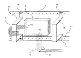
次に、制御回路の配置の具体的な構成を図2および図3において説明する。
図2において、マルチリレー6は前面扉2の裏面に固定されて取り付けられており、その一部は前面扉2の窓を貫通して正面に現れるようになっている。前面扉2の裏面にはマルチリレー6を挟むように上下2本の器具取り付けフレーム(第1支持フレーム)12が平行して溶接などで固定されている。上下の器具取り付けフレーム12間には、制御用の補助機器8をマルチリレー6の背面に配置するための凸形の背面配置用フレーム(第2支持フレーム)13が、ネジなどの締結部14によって左右に2個固定されている。左右の背面配置用フレーム13には制御用の補助機器8をマルチリレー6の背面に配置するための取付板15が固定的に取付されている。そして取付板15に制御用の補助機器8が搭載されて取付され、マルチリレー6の背面に制御用の補助機器8が配置される。
Next, a specific configuration of the control circuit will be described with reference to FIGS.
In FIG. 2, the multi-relay 6 is fixed and attached to the back surface of the
更に、マルチリレー6と計器用変流器4の二次端子とが接続される配線10およびマルチリレー6と計器用変圧器5の二次端子とが接続される配線11と、マルチリレー6と制御用の補助機器8の間を接続している配線7(以下、制御用配線7と称することもある)のマルチリレー6に対する接続位置の関係は、図2から取付板15と補助機器8を省略した図3から明確なように、マルチリレー6と計器用変流器4の二次端子とが接続される配線10およびマルチリレー6と計器用変圧器5の二次端子とが接続される配線11のマルチリレー6に対する接続面6aがマルチリレー6の下側の面にあるので、マルチリレー6
と制御用の補助機器8の間を接続している制御用配線7のマルチリレー6に対する接続面6bはマルチリレー6の左側の面で行なう構成としている。
したがって、マルチリレー6と計器用変流器4の二次端子とが接続される配線10およびマルチリレー6と計器用変圧器5の二次端子とが接続される配線11は、マルチリレー6と制御用の補助機器8の間を接続している制御用配線7とはマルチリレー6に対する接続面6a、6b付近で配線が平行しないように分離した配線経路となっている。
Furthermore, the
The
Therefore, the
図2のようにマルチリレー6の背面に制御用の補助機器8を配置することで、制御用の補助機器8を配置するスペースを削減することができ、その削減スペースに他の機器を追加するなど有効活用することができるようになる。また、図2のような背面配置にすることで、マルチリレー6と補助機器8とを接続する配線7を、計器用変成器(計器用変流器4と計器用変圧器5)の二次端子とマルチリレー6とを接続する配線10、11から分離した配線経路にすることができると共に、マルチリレー6と制御用の補助機器8の間を接続している配線7を最短化することができ、配線材料費の削減ができる。それと、制御用配線7を型取りした専用ケーブルとすることで整線作業を省略することができ、更なる加工費の削減もできる。
By arranging the control
なお、マルチリレー6と計器用変流器4の二次端子とが接続される配線10およびマルチリレー6と計器用変圧器5の二次端子とが接続される配線11のマルチリレー6への接続面が下側にある場合、マルチリレー6と制御用の補助機器8とを接続する制御用配線7と配線経路を分離した構成とするには、制御用配線7をマルチリレー6の下側以外の面で行なう構成にすることで、同じように配線経路の分離が可能になる。
このように、マルチリレー6と計器用変流器4の二次端子とが接続される配線10およびマルチリレー6と計器用変圧器5の二次端子とが接続される配線11と、制御用配線7の配線経路の分離が行なえるようにするために、マルチリレー6と計器用変流器4の二次端子とが接続される配線10およびマルチリレー6と計器用変圧器5の二次端子とが接続される配線11が接続される接続面6aと、制御用配線7が接続される接続面6bが異なる面になるようにマルチリレー6の接続面を構成することで、配線経路の分離が行なえる。
The
Thus, the
以上のように実施の形態1のスイッチギヤにおいては、制御用の補助機器8をマルチリレー6の背面に配置し、マルチリレー6と補助機器8とを接続する制御用配線7の接続面と、計器用変成器4、5の二次端子とマルチリレー6とを接続する配線10、11の接続面とを異なる面としているから、マルチリレー6に接続される制御用配線7と計器用変成器4、5の二次配線10、11との配線経路を分離することができるので、計器用変成器の二次配線10、11から制御用配線7に移行してくるサージを抑制することができる。また、制御用の補助機器8をマルチリレー6の背面に配置したことで、従来と比較して、制御用配線7の線長を大幅に短縮できるので配線材料費の削減ができる。それと、制御用配線7を型取りした専用ケーブルとすることで整線作業を省略することができ、更なる加工費の削減もできる。
As described above, in the switchgear according to the first embodiment, the control
実施の形態2.
次にこの発明の実施の形態2におけるスイッチギヤを図4に基づいて説明する。図4は制御回路の配置構成の斜視図を示しており、実施の形態1の図2に相当する図である。
この発明の実施の形態2によるスイッチギヤは、制御用の補助機器8をマルチリレー6の背面に配置した状態で、前面扉に対して可動式にしたものである。図4において、図1及び図2と同一の符号を付したものは、同一又はこれに相当するものである。
Next, the switchgear in
The switchgear according to
図4において、取付板15は凸形の背面配置用フレーム(第2支持フレーム)13の一方に軸体16などで回転可能に軸支されている。制御用の補助機器8は回転可能な取付板15に搭載されて固定されている。こうして制御用の補助機器8はマルチリレー6の背面に回転可能な可動式の取付板15に取り付け配置される。なお図示していないが、取付板15の可動側とは反対側の自由端には取付板15と背面配置用フレーム(第2支持フレーム)13とを係脱自在に固定する留め具が設けられる。
図4のように取付板15を回転可能に可動とすることで、マルチリレー6の背面に制御用の補助機器8を配置した構成でも、マルチリレー6の結線作業を行なうときには、制御用の補助機器8を取付板15に取り付けた状態で開閉できるので、マルチリレー6と制御用の補助機器8とを接続している制御用配線7を外すことなく、マルチリレー6と計器用変流器4の二次端子とが接続される配線10およびマルチリレー6と計器用変圧器5の二次端子とが接続される配線11の作業空間を確保することができる。
In FIG. 4, the mounting
As shown in FIG. 4, by making the mounting
図4ではマルチリレー6と計器用変流器4の二次端子とが接続される配線10およびマルチリレー6と計器用変圧器5の二次端子とが接続される配線11の接続をマルチリレー6の下側で行ったときに、マルチリレー6と補助機器8とを接続する制御用配線7の取り合いはマルチリレー6および補助機器8の左側で行なっている。このような構成の場合には、図4に示すように左側の凸形の背面配置用フレーム(第2支持フレーム)13と取付板15の左側で可動部を設け、垂直方向を軸にした構成とする。しかし、制御用配線7のマルチリレー6との取り合い位置がマルチリレー6および補助機器8の上側にある場合は、可動部は水平方向を軸にした構成であっても良い。
In FIG. 4, the connection of the
実施の形態3.
次にこの発明の実施の形態3におけるスイッチギヤを図5に基づいて説明する。図5は制御回路の配置構成の斜視図を示しており、実施の形態1の図2に相当する図である。
この発明の実施の形態3によるスイッチギヤは、制御用の補助機器8をマルチリレー6の背面に配置した状態で、前面扉に対してスライド式に可動にしたものである。図5において、図1及び図2と同一の符号を付したものは、同一又はこれに相当するものである。
Embodiment 3 FIG.
Next, the switchgear in Embodiment 3 of this invention is demonstrated based on FIG. FIG. 5 is a perspective view of the arrangement configuration of the control circuit, and corresponds to FIG. 2 of the first embodiment.
The switchgear according to Embodiment 3 of the present invention is slidably movable with respect to the front door in a state in which the
図5において、背面配置用フレーム(第2支持フレーム)13aは、上下2本の器具取り付けフレーム(第1支持フレーム)12にネジなどの締結部14によってそれぞれ上下に固定されたL型の背面配置用フレームとし、このL型の背面配置用フレーム(第2支持フレーム)13aの背面部には長孔13bが水平方向に設けられている。そして取付板15が長孔13bに沿って可動可能にスライドするようになっている。制御用の補助機器8はスライド可能な取付板15に搭載されて固定されている。こうして制御用の補助機器8はマルチリレー6の背面に可動式の取付板15に取り付け配置される。
In FIG. 5, the rear surface arrangement frame (second support frame) 13 a is an L-shaped rear surface arrangement fixed to the upper and lower two instrument mounting frames (first support frame) 12 by
図5のように取付板15をスライド式に可動とすることで、マルチリレー6の背面に制御用の補助機器8を配置した構成でも、マルチリレー6の結線作業を行なうときには、制御用の補助機器8を取付板15に取り付けた状態で開閉できるので、マルチリレー6と制御用の補助機器8とを接続している制御用配線7を外すことなく、マルチリレー6と計器用変流器4の二次端子とが接続される配線10およびマルチリレー6と計器用変圧器5の二次端子とが接続される配線11の作業空間を確保することができる。即ち、計器用変成器4、5の二次端子に接続された配線10、11をマルチリレー6に接続する際は、補助機器8が固定された取付板15を図の左側にスライドさせることで結線の作業空間を確保することができる。
As shown in FIG. 5, by making the mounting
実施の形態4.
次にこの発明の実施の形態4におけるスイッチギヤを図6〜図8に基づいて説明する。図6は制御回路の配置構成の斜視図を示しており、実施の形態1の図2に相当する図である。図7および図8はノイズをシールドする為の構造を説明するための図である。
この発明の実施の形態4によるスイッチギヤは、マルチリレー6と制御用の補助機器8
をノイズからシールドするようにした構成にしたものである。図6〜図8において、図1及び図2と同一の符号を付したものは、同一又はこれに相当するものである。
Embodiment 4 FIG.
Next, a switchgear according to Embodiment 4 of the present invention will be described with reference to FIGS. FIG. 6 is a perspective view of the arrangement configuration of the control circuit, and corresponds to FIG. 2 of the first embodiment. 7 and 8 are diagrams for explaining a structure for shielding noise.
A switchgear according to Embodiment 4 of the present invention includes a
Is configured to shield from noise. 6 to 8, the same reference numerals as those in FIGS. 1 and 2 denote the same or corresponding parts.
図6において、取付板15は実施の形態2のように背面配置用フレーム(第2支持フレーム)13に可動可能なように取付されている。制御用の補助機器8はマルチリレー6と対向するように取付板15の内面に搭載されている。凸形の背面配置用フレーム(第2支持フレーム)13の上下および左右の4方の面にはマルチリレー6と制御用の補助機器8を包囲するようにノイズを電磁シールドできるシールドパネル17が取り付けられている。また取付板15はノイズを電磁シールドできる材質にする。したがって取付板15を閉じた状態にしたときに、マルチリレー6と制御用の補助機器8は取付板15とシールドパネル17で閉じた空間に配置されることになる。
In FIG. 6, the mounting
ノイズのシールド性を高くするために、図6の上下に配置したシールドパネル17と可動式の取付板15の接触は、図7に示す構成のように、取付板15の上端および下端からシールドパネル17側に延びる延長部15aを設けるようにする。また図6の左右に配置した背面配置用フレーム(第2支持フレーム)13と可動式の取付板15の接触は、図8に示す構成のように、接触部分を大きくする。
なお、シールドパネル17と取付板15および背面配置用フレーム(第2支持フレーム)13との接触の取り方は上記の方式に拠らなくても、ノイズが電磁シールドできる構成であれば何れの方式でも良い。
In order to enhance the noise shielding performance, the
In addition, the method of taking contact between the
図6の構成では、マルチリレー6と制御用の補助機器8とを接続する配線7は、取付板15とシールドパネル17で閉じた空間に配置される。マルチリレー6と計器用変流器4の二次端子とが接続される配線10およびマルチリレー6と計器用変圧器5の二次端子とが接続される配線11は、マルチリレー6の下側で接続されるときは、下側に配置したシールドパネル17に穴を空けてコネクタ(図示省略)を設け、このコネクタを介してマルチリレー6と計器用変成器4、5の二次配線10、11とが接続されるようにすることでシールドは保たれる。
In the configuration of FIG. 6, the
実施の形態4のスイッチギヤにおいては、マルチリレー6と制御用の補助機器8の周囲は、ノイズをシールドできるシールドパネル17で囲い、可動式の取付板15はノイズをシールドできる材質にしているから、外部から進入してくるノイズをシールドすることができ、スイッチギヤの信頼性を高くすることができる。
なお、図6では背面配置用フレーム(第2支持フレーム)13の側面にシールドパネル17を固定して筐体にする構成としているが、背面配置用フレーム(第2支持フレーム)13をシールドできるパネルで箱体に構成し、マルチリレー6と制御用の補助機器8を一括で覆う構成としたものでもよい。また取付板15は可動式でなく、図2に示すような固定式のものにして、シールドした筐体にマルチリレー6と制御用の補助機器8を一括で覆う構成としてもよい。
In the switchgear of the fourth embodiment, the periphery of the
In FIG. 6, the
実施の形態5.
また、図6のようにマルチリレー6と制御用の補助機器8をシールドパネル17で囲った構成とした時に、シールドパネル17に放熱用のスリットを設けた構成としたものとすると、一層信頼性が高まる。このとき、スリットの穴径は、対象とするノイズの半波長より小さな穴径にすることで、ノイズの侵入を防ぐことができる。
Embodiment 5 FIG.
Further, when the
1:箱体 2:前面扉
3:遮断器 4:計器用変流器(計器用変成器)
5:計器用変圧器(計器用変成器) 6:マルチリレー
6a、6b:接続面
7:マルチリレーと補助機器間の配線 8:制御用の補助機器
9a、9b:配線用ダクト
10:計器用変流器二次端子とマルチリレー間の配線
11:計器用変圧器二次端子とマルチリレー間の配線
12:器具取り付けフレーム(第1支持フレーム)
13、13a:背面配置用フレーム(第2支持フレーム) 13b:長孔
14:締結部 15:取付板
16:軸体 17:シールドパネル。
1: Box 2: Front door 3: Circuit breaker 4: Instrument current transformer (instrument transformer)
5: Transformer for instrument (transformer for instrument) 6: Multi-relay 6a, 6b: Connection surface 7: Wiring between multi-relay and auxiliary equipment 8: Auxiliary equipment for
13, 13a: Rear arrangement frame (second support frame) 13b: Long hole 14: Fastening portion 15: Mounting plate 16: Shaft body 17: Shield panel.
Claims (7)
Priority Applications (1)
| Application Number | Priority Date | Filing Date | Title |
|---|---|---|---|
| JP2009102947A JP5220680B2 (en) | 2009-04-21 | 2009-04-21 | Switchgear |
Applications Claiming Priority (1)
| Application Number | Priority Date | Filing Date | Title |
|---|---|---|---|
| JP2009102947A JP5220680B2 (en) | 2009-04-21 | 2009-04-21 | Switchgear |
Related Child Applications (1)
| Application Number | Title | Priority Date | Filing Date |
|---|---|---|---|
| JP2013044115A Division JP5542986B2 (en) | 2013-03-06 | 2013-03-06 | Switchgear |
Publications (3)
| Publication Number | Publication Date |
|---|---|
| JP2010259142A JP2010259142A (en) | 2010-11-11 |
| JP2010259142A5 JP2010259142A5 (en) | 2012-01-26 |
| JP5220680B2 true JP5220680B2 (en) | 2013-06-26 |
Family
ID=43319435
Family Applications (1)
| Application Number | Title | Priority Date | Filing Date |
|---|---|---|---|
| JP2009102947A Active JP5220680B2 (en) | 2009-04-21 | 2009-04-21 | Switchgear |
Country Status (1)
| Country | Link |
|---|---|
| JP (1) | JP5220680B2 (en) |
Cited By (1)
| Publication number | Priority date | Publication date | Assignee | Title |
|---|---|---|---|---|
| US10084306B2 (en) | 2015-04-13 | 2018-09-25 | Lsis Co., Ltd. | Circuit breaker having safety switching part |
Families Citing this family (2)
| Publication number | Priority date | Publication date | Assignee | Title |
|---|---|---|---|---|
| JP5692744B2 (en) * | 2010-11-30 | 2015-04-01 | テンパール工業株式会社 | Residential distribution board |
| JP6626382B2 (en) * | 2016-03-18 | 2019-12-25 | 株式会社Subaru | Power supply |
Family Cites Families (5)
| Publication number | Priority date | Publication date | Assignee | Title |
|---|---|---|---|---|
| JPH0525903U (en) * | 1991-09-12 | 1993-04-02 | 日新電機株式会社 | Switch gear |
| JPH06165319A (en) * | 1992-11-17 | 1994-06-10 | Toshiba Corp | Control center |
| JP2876372B2 (en) * | 1992-12-17 | 1999-03-31 | 三菱電機株式会社 | Metal closed switchgear |
| JP4301658B2 (en) * | 1999-11-01 | 2009-07-22 | 三菱電機株式会社 | Switchgear |
| JP4681030B2 (en) * | 2008-07-10 | 2011-05-11 | 三菱電機株式会社 | Switchgear connection circuit and switchgear using the same |
-
2009
- 2009-04-21 JP JP2009102947A patent/JP5220680B2/en active Active
Cited By (1)
| Publication number | Priority date | Publication date | Assignee | Title |
|---|---|---|---|---|
| US10084306B2 (en) | 2015-04-13 | 2018-09-25 | Lsis Co., Ltd. | Circuit breaker having safety switching part |
Also Published As
| Publication number | Publication date |
|---|---|
| JP2010259142A (en) | 2010-11-11 |
Similar Documents
| Publication | Publication Date | Title |
|---|---|---|
| JP4611425B2 (en) | Wiring device with electromagnetic switchgear | |
| US8787004B2 (en) | Medium voltage circuit breaker with integrated electronic protection unit | |
| EP3330993B1 (en) | Molded case circuit breaker | |
| JP5220680B2 (en) | Switchgear | |
| JP5542986B2 (en) | Switchgear | |
| EP2953219B1 (en) | Gas-insulated switchgear | |
| US20230275406A1 (en) | Modular instrument compartment | |
| JP5787275B2 (en) | Switchgear | |
| JP2006014500A (en) | Cubicle | |
| BRPI0721896A2 (en) | ELECTROMAGNETIC SWITCHING DEVICE THAT HAS A MULTIPLE OF GRADUATE AREAS IN RELATION TO THE OTHER | |
| CN110943391A (en) | High-voltage distribution box | |
| JP2008099497A (en) | Door structure for panelboard | |
| US20130026856A1 (en) | Electrical disconnect assembly with separate disconnect compartment, such that safety handle mechanism does not provide access to the disconnecting device or any energized parts or conductors. | |
| JP6979869B2 (en) | Power supply | |
| JPH0134482Y2 (en) | ||
| CN108475902B (en) | Switching device | |
| JP2876372B2 (en) | Metal closed switchgear | |
| JP2010268648A (en) | Box for housing electric apparatus | |
| CN216981138U (en) | Integrated form block terminal convenient to plug wiring | |
| CN210404406U (en) | Automatically controlled cabinet of modularization | |
| JP2013215062A (en) | Metal enclosed type switchgear | |
| JP2018129873A (en) | Switch board | |
| US20240356312A1 (en) | Electrical panelboard with arc fault protection and user interface | |
| JP2001177924A (en) | Box structure of power distribution board | |
| JP2024101087A (en) | Terminal unit, breaker, and electric board |
Legal Events
| Date | Code | Title | Description |
|---|---|---|---|
| A521 | Written amendment |
Free format text: JAPANESE INTERMEDIATE CODE: A523 Effective date: 20111202 |
|
| A621 | Written request for application examination |
Free format text: JAPANESE INTERMEDIATE CODE: A621 Effective date: 20111202 |
|
| A977 | Report on retrieval |
Free format text: JAPANESE INTERMEDIATE CODE: A971007 Effective date: 20130118 |
|
| TRDD | Decision of grant or rejection written | ||
| A01 | Written decision to grant a patent or to grant a registration (utility model) |
Free format text: JAPANESE INTERMEDIATE CODE: A01 Effective date: 20130205 |
|
| A61 | First payment of annual fees (during grant procedure) |
Free format text: JAPANESE INTERMEDIATE CODE: A61 Effective date: 20130306 |
|
| FPAY | Renewal fee payment (event date is renewal date of database) |
Free format text: PAYMENT UNTIL: 20160315 Year of fee payment: 3 |
|
| R151 | Written notification of patent or utility model registration |
Ref document number: 5220680 Country of ref document: JP Free format text: JAPANESE INTERMEDIATE CODE: R151 |
|
| FPAY | Renewal fee payment (event date is renewal date of database) |
Free format text: PAYMENT UNTIL: 20160315 Year of fee payment: 3 |
|
| R250 | Receipt of annual fees |
Free format text: JAPANESE INTERMEDIATE CODE: R250 |
|
| R250 | Receipt of annual fees |
Free format text: JAPANESE INTERMEDIATE CODE: R250 |
|
| R250 | Receipt of annual fees |
Free format text: JAPANESE INTERMEDIATE CODE: R250 |
|
| R250 | Receipt of annual fees |
Free format text: JAPANESE INTERMEDIATE CODE: R250 |
|
| R250 | Receipt of annual fees |
Free format text: JAPANESE INTERMEDIATE CODE: R250 |
|
| R250 | Receipt of annual fees |
Free format text: JAPANESE INTERMEDIATE CODE: R250 |
|
| R250 | Receipt of annual fees |
Free format text: JAPANESE INTERMEDIATE CODE: R250 |
|
| R250 | Receipt of annual fees |
Free format text: JAPANESE INTERMEDIATE CODE: R250 |