EP2953219B1 - Gas-insulated switchgear - Google Patents
Gas-insulated switchgear Download PDFInfo
- Publication number
- EP2953219B1 EP2953219B1 EP14864994.0A EP14864994A EP2953219B1 EP 2953219 B1 EP2953219 B1 EP 2953219B1 EP 14864994 A EP14864994 A EP 14864994A EP 2953219 B1 EP2953219 B1 EP 2953219B1
- Authority
- EP
- European Patent Office
- Prior art keywords
- gas
- insulated switchgear
- operating mechanism
- pressure tank
- housing
- Prior art date
- Legal status (The legal status is an assumption and is not a legal conclusion. Google has not performed a legal analysis and makes no representation as to the accuracy of the status listed.)
- Active
Links
- 238000009434 installation Methods 0.000 claims description 6
- 230000000694 effects Effects 0.000 description 6
- 239000004020 conductor Substances 0.000 description 4
- 238000009413 insulation Methods 0.000 description 3
- 230000001131 transforming effect Effects 0.000 description 2
- 239000000853 adhesive Substances 0.000 description 1
- 230000001070 adhesive effect Effects 0.000 description 1
- 230000005540 biological transmission Effects 0.000 description 1
- 238000012423 maintenance Methods 0.000 description 1
- 238000004519 manufacturing process Methods 0.000 description 1
- 239000002184 metal Substances 0.000 description 1
- 238000000034 method Methods 0.000 description 1
- 230000000087 stabilizing effect Effects 0.000 description 1
Images


Classifications
-
- H—ELECTRICITY
- H02—GENERATION; CONVERSION OR DISTRIBUTION OF ELECTRIC POWER
- H02B—BOARDS, SUBSTATIONS OR SWITCHING ARRANGEMENTS FOR THE SUPPLY OR DISTRIBUTION OF ELECTRIC POWER
- H02B13/00—Arrangement of switchgear in which switches are enclosed in, or structurally associated with, a casing, e.g. cubicle
- H02B13/02—Arrangement of switchgear in which switches are enclosed in, or structurally associated with, a casing, e.g. cubicle with metal casing
- H02B13/035—Gas-insulated switchgear
- H02B13/0358—Connections to in or out conductors
-
- H—ELECTRICITY
- H02—GENERATION; CONVERSION OR DISTRIBUTION OF ELECTRIC POWER
- H02B—BOARDS, SUBSTATIONS OR SWITCHING ARRANGEMENTS FOR THE SUPPLY OR DISTRIBUTION OF ELECTRIC POWER
- H02B13/00—Arrangement of switchgear in which switches are enclosed in, or structurally associated with, a casing, e.g. cubicle
- H02B13/02—Arrangement of switchgear in which switches are enclosed in, or structurally associated with, a casing, e.g. cubicle with metal casing
- H02B13/035—Gas-insulated switchgear
- H02B13/0354—Gas-insulated switchgear comprising a vacuum switch
-
- H—ELECTRICITY
- H02—GENERATION; CONVERSION OR DISTRIBUTION OF ELECTRIC POWER
- H02B—BOARDS, SUBSTATIONS OR SWITCHING ARRANGEMENTS FOR THE SUPPLY OR DISTRIBUTION OF ELECTRIC POWER
- H02B13/00—Arrangement of switchgear in which switches are enclosed in, or structurally associated with, a casing, e.g. cubicle
- H02B13/02—Arrangement of switchgear in which switches are enclosed in, or structurally associated with, a casing, e.g. cubicle with metal casing
- H02B13/035—Gas-insulated switchgear
- H02B13/0356—Mounting of monitoring devices, e.g. current transformers
Landscapes
- Engineering & Computer Science (AREA)
- Power Engineering (AREA)
- Gas-Insulated Switchgears (AREA)
Description
- The present invention relates to a gas-insulated switchgear that is used in power transmission/distribution facilities, power receiving equipment, and the like.
- A gas-insulated switchgear is a main device forming power receiving/transforming facilities, and requires not only reliability, safety, and the labor saving of maintenance but also a reduction in size and cost. Further, the gas-insulated switchgear is subject to various restrictions due to the disposition of other devices of the power receiving/transforming facilities.
- For example, the restrictions include whether a lead-in position where the external cable is led into the gas-insulated switchgear is present at an upper or lower portion of the gas-insulated switchgear.
- Even though the lead-in position of the external cable is present at any one of the upper and lower portions in a gas-insulated switchgear in the related art, it is possible to cope with the structure of the gas-insulated switchgear by using the same components. Accordingly, the cost of the gas-insulated switchgear is reduced (for example, see PTL 1).
- That is, a circuit breaker body is installed in the rear of a control panel that is installed on a floor with a base interposed therebetween, the height of the central axis of the circuit breaker is set to be greater than the sum of a distance between the central axis of the circuit breaker and the upper surface of a bus container and the height of the base, and an operating unit is disposed at the center of the entire gas-insulated switchgear.
- When the height of the central axis of the circuit breaker is set as described above, it is possible to cope with the structure of the gas-insulated switchgear by using the same components regardless of the lead-in position of the external cable. Accordingly, standardization is possible and an effect of easily producing the gas-insulated switchgear and reducing cost is obtained.
-
PTL 2 to 5 each relate to gas-insulated switchgears of the prior art generally according to the preamble ofclaim 1. -
- PTL 1: JP-UM-
A-5-74109 page 1 andFIG. 1 ) - PTL 2:
US2005/219804 A1 - PTL 3:
JP H08 340610 A - PTL 4:
EP 1 160 945 A1 - PTL 5:
EP 1 107 408 A1 - In the above-mentioned gas-insulated switchgear, it is possible to reduce cost by forming a sufficient space below the circuit breaker and disposing the operating unit at the center of the entire gas-insulated switchgear so that a problem is not generated even though the above-mentioned gas-insulated switchgear is inverted vertically about the circuit breaker as a center. However, since an excessive space is required, there is a problem in that the size of the device is increased.
- An object of the invention is to provide a gas-insulated switchgear which can cope with the lead-in direction of an external cable of a gas-insulated switchgear and of which the height can be reduced in comparison with that in the related art.
- A gas-insulated switchgear according to the invention is given in
claim 1. - According to the gas-insulated switchgear of the invention, the pressure tank, the circuit breaker operating mechanism, and the disconnector operating mechanism form an integrated structure in advance and the integrated structure is rotated, supported, and received in the housing in accordance with the lead-in direction of the external cable.
- Accordingly, the same tank structure can be used regardless of a difference in the lead-in direction of the external cable, and the height of the gas-insulated switchgear can be reduced in comparison with that in the related art.
- Other objects, characteristics, standpoints, and effects of the invention are further apparent from the following detailed description of the invention referring to drawings.
-
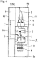
- FIG. 1
- is a side cross-sectional view schematically showing the internal layout of a gas-insulated switchgear according to the embodiment of the invention when the gas-insulated switchgear is used so that an external cable is led out of a lower portion of the gas-insulated switchgear.
- FIG. 2
- is a side cross-sectional view showing the specific product structure of the gas-insulated switchgear of
FIG. 1 . - FIG. 3
- is a side cross-sectional view schematically showing the internal layout of the gas-insulated switchgear according to the embodiment of the invention when the gas-insulated switchgear is used so that an external cable is led out of an upper portion of the gas-insulated switchgear.
- FIG. 4
- is a side cross-sectional view showing the specific product structure of the gas-insulated switchgear of
FIG. 3 . - FIG. 5
- is a side cross-sectional view schematically showing the internal layout of a gas-insulated switchgear according an example not covered by the claims.
- A gas-insulated switchgear according to the embodiment of the invention will be described below with reference to
FIGS. 1 to 4 . Meanwhile,FIG. 1 is a side cross-sectional view schematically showing the internal layout of the gas-insulated switchgear according to the embodiment of the invention.FIG. 2 is a side cross-sectional view showing the specific product structure of the gas-insulated switchgear ofFIG. 1 . -
FIGS. 1 and2 show the structure of the gas-insulated switchgear when the gas-insulated switchgear is used so that an external cable connected to a circuit breaker is led out of a lower portion of the gas-insulated switchgear. -
FIG. 3 is a side cross-sectional view schematically showing the internal layout of the gas-insulated switchgear according to the embodiment of the invention.FIG. 4 is a side cross-sectional view showing the specific product structure of the gas-insulated switchgear ofFIG. 3 . -
FIGS. 3 and4 show the structure of the gas-insulated switchgear when the gas-insulated switchgear is used so that an external cable is led out of an upper portion of the gas-insulated switchgear. - Meanwhile, the same reference numerals denote the same or corresponding portions in the respective drawings.
- As shown in
FIGS. 1 and2 , a gas-insulatedswitchgear 100 includes apressure tank 3,buses 4, anexternal cable 5, adisconnector operating mechanism 6, a circuitbreaker operating mechanism 7, and acontrol box 8 that are received in ahousing 9. - A
disconnector 1 and acircuit breaker 2 are received in thepressure tank 3. Thedisconnector operating mechanism 6 operates thedisconnector 1. The circuitbreaker operating mechanism 7 operates thecircuit breaker 2. - A control circuit is received in the
control box 8. Here, thedisconnector 1 means a three position disconnector in which the function of a disconnector and the function of a grounding switch are integrated with each other. - Further, the
pressure tank 3 is made of metal, and an insulating gas is sealed in thepressure tank 3. Furthermore, thehousing 9 includes a frame and panels so as to surround the periphery of the components. - Moreover, a cable-side bushing 10 as an external cable-connecting portion is installed at a portion of the
pressure tank 3 that is connected to theexternal cable 5, and bus-side bushings 11 as bus-connecting portions are installed at a portion of thepressure tank 3 that is connected to thebuses 4. - Further, a
door 9a is provided on a portion of thehousing 9 that is positioned in front of thedisconnector operating mechanism 6 and the circuitbreaker operating mechanism 7, and adoor 9b is provided on a portion of the housing that is positioned in front of thecontrol box 8. Meanwhile, the installation position of thecontrol box 8 is not changed even though the lead-in direction of theexternal cable 5 is changed. - Further, a CT (current transformer) 12, which is a sensor concentrically mounted and measuring a main circuit current, is installed on the outer periphery of the cable-
side bushing 10. Meanwhile, theexternal cable 5, the cable-side bushing 10, thecircuit breaker 2, thedisconnector 1, the bus-side bushings 11, and thebuses 4 are formed in this order as a current flow path. - The
pressure tank 3, thedisconnector operating mechanism 6, and the circuitbreaker operating mechanism 7, which have been described above, are integrated in advance to form an integrated structure. Moreover, the integrated structure is rotated, supported, and received in thehousing 9 in accordance with the lead-in direction of theexternal cable 5, so that theexternal cable 5 can be adapted so as to be received and fixed in any aspect of the aspects ofFIGS. 2 and4 . -
FIGS. 1 and2 show a structure in which theexternal cable 5 is led in from the lower portion of the gas-insulatedswitchgear 100, and a gas-insulatedswitchgear 100A ofFIGS. 3 and4 has a structure in which theexternal cable 5 is led in from the upper portion of the gas-insulated switchgear. - Accordingly, the integrated structure, which includes the
pressure tank 3, thedisconnector operating mechanism 6, and the circuitbreaker operating mechanism 7, is inverted vertically and supported. - When the shapes or structures of a
top plate 9c and abottom plate 9d of thehousing 9 can be arbitrarily changed in accordance with the lead-in direction of theexternal cable 5, thehousing 9 can easily cope with the inversion of the integrated structure. - For example, a known technique, such as forming an opening into which the
external cable 5 is inserted at each of thetop plate 9c and thebottom plate 9d and mounting a lid on the opening into which theexternal cable 5 is not inserted, can be appropriately applied. - Meanwhile, it is not preferable that a dial (not shown), which appears during the opening of the
door 9a, is installed in front of thedisconnector operating mechanism 6 and the circuitbreaker operating mechanism 7, and displays an operating direction and the like, be inverted vertically together when thepressure tank 3, thedisconnector operating mechanism 6, and the circuitbreaker operating mechanism 7 integrated in advance are inverted vertically. - For this reason, it is possible to easily cope with the inversion of the integrated structure by forming a dial with, for example, a seal in which an adhesive is applied to the back and attaching to the integrated structure after the determination of the vertical direction of the integrated structure.
- Further, when, for example, a counter or the like provided on the
disconnector operating mechanism 6 or the circuitbreaker operating mechanism 7 is inverted vertically due to the inversion of thepressure tank 3 and the like, it is possible to cope with the inversion of the integrated structure by detaching the counter or the like once and reattaching the counter or the like in a posture in which the counter or the like corresponds to thedisconnector operating mechanism 6 or the circuitbreaker operating mechanism 7 in a vertical direction. - Next, an example of the connection between the
pressure tank 3 and theexternal cable 5 and thebuses 4 will be described. - The cable-
side bushing 10 for three phases, which is the external cable-connecting portion, is airtightly provided on a through hole (not shown) that is formed at the floor of thepressure tank 3. Theexternal cable 5 is electrically connected to a conductor, which is provided in thepressure tank 3, through a conductor passing through the cable-side bushing 10, so that an electric path is formed. - The bus-
side bushings 11 for three phases, which are the bus-connecting portions, are airtightly provided on through holes (not shown) that are formed at the upper surface portion of thepressure tank 3. Thebuses 4 are electrically connected to conductors, which are provided in thepressure tank 3, through conductors passing through the bus-side bushings 11, so that a current flow path is formed. - The
bus 4 is, for example, a solid-insulation bus, and it is preferable that thebus 4 be provided with a ground screen. When a solid-insulation bus is used, gas treatment is not necessary. Since thebuses 4 are inserted into the bus-side bushings 11 and can be mounted by screwing, work can be performed even in a relatively small space. - Next, general combinations, when the cable-
side bushing 10 and theexternal cable 5 corresponding to the cable-side bushing 10 are connected to each other, will be described. - A: Gas terminal cable and bushing including a gas-insulation portion.
- B: Linear slip-on connection bushing (male) and linear slip-on cable (female).
- C: Linear slip-on connection bushing (female) and linear slip-on cable (male).
- Gas treatment is not necessary in all the combinations A, B, and C. Further, in regard to the respective characteristics, the terminal treatment of A is easiest but a terminal distance of A is long, and a bit of time is required for the terminal treatment of B and C but a terminal distance of B and C is short.
- A gas-insulated switchgear can be selected according to specifications of the delivery destination of the gas-insulated switchgear on the basis of these characteristics.
- Meanwhile, the gas-insulated
switchgear 100A shown inFIG. 3 has a structure in which theexternal cable 5 is led in from the upper portion of thehousing 9. In the gas-insulatedswitchgear 100A, thepressure tank 3 described in the gas-insulatedswitchgear 100 ofFIG. 1 and thedisconnector operating mechanism 6 and the circuitbreaker operating mechanism 7 installed outside thepressure tank 3 are integrally inverted vertically and the shape of thehousing 9 is changed so that theexternal cable 5 is led in from the upper portion. - For this purpose, structures, such as mounting portions or fixing portions for devices received in the
housing 9, are formed in advance so as to correspond to the structures of both thehousing 9 and the devices received in thehousing 9 so that thepressure tank 3, thedisconnector operating mechanism 6, and the circuitbreaker operating mechanism 7 are mounted at a height where the minimum space required for the installation of thebuses 4 can be ensured from the floor of the gas-insulatedswitchgear 100A. - As described above, according to the embodiment, the
pressure tank 3 receiving the threeposition disconnector 1 and thecircuit breaker 2, thedisconnector operating mechanism 6, and the circuitbreaker operating mechanism 7 are adapted so as to be capable of being integrally inverted vertically in accordance with the lead-in direction of theexternal cable 5, and thetop plate 9c and thebottom plate 9d of thehousing 9 are changed so as to be capable of being exchanged. - Accordingly, it is possible to mount the
pressure tank 3, thedisconnector operating mechanism 6, and the circuitbreaker operating mechanism 7 only by ensuring a terminal distance required for the connection between theexternal cable 5 and the cable-side bushing 10, when the external cable is led in from the lower portion, and ensuring a dimension required for the connection between thebus 4 and the bus-side bushing 11 from the floor of the switchgear when the external cable is led in from the upper portion. As a result, it is possible to obtain a gas-insulated switchgear of which the height is smaller than that in the related art.
Since the gas-insulatedswitchgears same pressure tank 3 and the same operating mechanism regardless of the lead-in direction of theexternal cable 5, an effect of stabilizing quality by the complete unitization of assembly and an effect of reducing cost by mass production in comparison with the related art are obtained. -
FIG. 5 is a side cross-sectional view schematically showing the internal layout of a gas-insulated switchgear according to an example not covered by the claims. Meanwhile, the gas-insulatedswitchgear 100B of this example uses apressure tank 3A of which the shape is changed so that a cable-side bushing 10 and bus-side bushings 11 are mounted on the surface perpendicular to the floor. - In
FIG. 5 , thepressure tank 3A is formed in a protruding shape, in which steppedportions disconnector operating mechanism 6 and the circuitbreaker operating mechanism 7 provided on the front surface side (the left side inFIG. 5 ) are mounted, in side view. - The cable-
side bushing 10 is mounted on the steppedportion 31 that forms one vertical surface formed in a stepped shape, and the bus-side bushings 11 are mounted on the steppedportion 32 that forms the other vertical surface. - Since the cable-
side bushing 10 is mounted on one steppedportion 31 and the bus-side bushings 11 are mounted on the other steppedportion 32 as described above, the height of thehousing 9 on which thebuses 4 for three phases are arranged in the vertical direction is greater than that of the housing of the gas-insulatedswitchgear 100 described in the embodiment. - However, since the cable-
side bushing 10 and the bus-side bushings 11 are horizontally installed together, a total height is rather reduced and thebuses 4 and theexternal cable 5 can be mounted from the front surface side of thehousing 9. Since other structures are the same as those of the embodiment shown inFIGS. 1 to 4 , the description thereof will be omitted. - In the example formed as described above, as in the embodiment, in order to change the structure of the gas-insulated
switchgear 100B into a structure in which theexternal cable 5 is led in from the upper portion of the gas-insulatedswitchgear 100B, thepressure tank 3A, thedisconnector operating mechanism 6, and the circuitbreaker operating mechanism 7 only have to be integrally inverted vertically and received and fixed to thehousing 9. - As a result, the
pressure tank 3A, thedisconnector operating mechanism 6, and the circuitbreaker operating mechanism 7 are mounted at a height where the minimum space required for the installation of thebuses 4 can be ensured. - When the gas-insulated
switchgear 100B described in the example is used, an effect described in the embodiment is obtained and installation work can be performed only in a space present on the front surface side of thehousing 9 at the delivery destination of the gas-insulatedswitchgear 100B. Accordingly, an installation space can be reduced in comparison with the related art.
Claims (1)
- A gas-insulated switchgear (100) comprising:- a pressure tank (3) in which a circuit breaker (2) and a disconnector (1) are received and an insulating gas is sealed;- a circuit breaker operating mechanism (7) that is installed outside the pressure tank (3) and operates the circuit breaker (2);- a disconnector operating mechanism (6) that is installed outside the pressure tank (3) and operates the disconnector (1); and- a housing (9) in which the pressure tank (3), the circuit breaker operating mechanism (7), and the disconnector operating mechanism (6) are received,- wherein the pressure tank (3), the circuit breaker operating mechanism (7), and the disconnector operating mechanism (6) are an integrated structure and are received in the housing (9),- characterised in that: the housing (9) and said integrated structure are so formed to allow mounting of said integrated structure in a first orientation such that a cable-side bushing (10) and bus-side bushings (11) installed on opposing sides of the pressure tank (3) align with buses (4) and an external cable (5), respectively,- when the external cable (5) is led in from the lower portion of the housing (9), and in a second orientation, vertically inverted with respect to the first orientation, when the external cable (5) is led in from the upper portion of the housing (9), and- wherein the housing (9) is so sized to ensure that a space below said integrated structure is just large enough to allow connection of the external cable (5) in the first orientation and the minimum space from the floor of the gas-insulated switchgear for installation of buses (4) in the second orientation, thus minimising the height of the housing (9).
Applications Claiming Priority (1)
| Application Number | Priority Date | Filing Date | Title |
|---|---|---|---|
| PCT/JP2014/061921 WO2015166545A1 (en) | 2014-04-29 | 2014-04-29 | Gas-insulated switchgear |
Publications (3)
| Publication Number | Publication Date |
|---|---|
| EP2953219A1 EP2953219A1 (en) | 2015-12-09 |
| EP2953219A4 EP2953219A4 (en) | 2016-04-13 |
| EP2953219B1 true EP2953219B1 (en) | 2021-05-26 |
Family
ID=52145667
Family Applications (1)
| Application Number | Title | Priority Date | Filing Date |
|---|---|---|---|
| EP14864994.0A Active EP2953219B1 (en) | 2014-04-29 | 2014-04-29 | Gas-insulated switchgear |
Country Status (5)
| Country | Link |
|---|---|
| EP (1) | EP2953219B1 (en) |
| JP (1) | JP5638726B1 (en) |
| CN (1) | CN105229879B (en) |
| HK (1) | HK1214415A1 (en) |
| WO (1) | WO2015166545A1 (en) |
Families Citing this family (4)
| Publication number | Priority date | Publication date | Assignee | Title |
|---|---|---|---|---|
| CN108988191B (en) * | 2018-09-30 | 2023-06-02 | 聂刚 | Gas-insulated metal-enclosed switchgear |
| EP3671989A1 (en) * | 2018-12-19 | 2020-06-24 | ABB Schweiz AG | Three phase switchgear using single phase equipment in single casing |
| EP3671986A1 (en) | 2018-12-19 | 2020-06-24 | ABB Schweiz AG | Switchgear |
| EP3671991A1 (en) | 2018-12-19 | 2020-06-24 | ABB Schweiz AG | Three phase switchgear or control gear |
Family Cites Families (8)
| Publication number | Priority date | Publication date | Assignee | Title |
|---|---|---|---|---|
| DE4103101C3 (en) * | 1990-03-22 | 1996-08-14 | Mitsubishi Electric Corp | Disconnector, as well as compressed gas-insulated manual transmission with such |
| JPH0574109U (en) * | 1992-03-09 | 1993-10-08 | 日新電機株式会社 | Gas insulated switchgear |
| JPH08340610A (en) * | 1995-06-09 | 1996-12-24 | Fuji Electric Co Ltd | Gas insulated switchgear |
| JP2001169420A (en) * | 1999-12-07 | 2001-06-22 | Meidensha Corp | Gas insulation switch gear |
| JP2001352623A (en) * | 2000-06-02 | 2001-12-21 | Mitsubishi Electric Corp | Gas-insulated switchgear |
| CN2574270Y (en) * | 2002-10-08 | 2003-09-17 | 李彤 | Sulfur hexafluoride gas insulation metal sealed switchgear |
| JP4329923B2 (en) * | 2002-10-31 | 2009-09-09 | 三菱電機株式会社 | Gas insulated switchgear |
| CN2919626Y (en) * | 2006-04-29 | 2007-07-04 | 江苏宝胜电气股份有限公司 | Digital three-phase integrated air inflation chamber separating module |
-
2014
- 2014-04-29 WO PCT/JP2014/061921 patent/WO2015166545A1/en active Application Filing
- 2014-04-29 JP JP2014534684A patent/JP5638726B1/en active Active
- 2014-04-29 CN CN201480003421.8A patent/CN105229879B/en active Active
- 2014-04-29 EP EP14864994.0A patent/EP2953219B1/en active Active
-
2016
- 2016-02-26 HK HK16102259.4A patent/HK1214415A1/en unknown
Non-Patent Citations (1)
| Title |
|---|
| None * |
Also Published As
| Publication number | Publication date |
|---|---|
| EP2953219A4 (en) | 2016-04-13 |
| JPWO2015166545A1 (en) | 2017-04-20 |
| EP2953219A1 (en) | 2015-12-09 |
| HK1214415A1 (en) | 2016-07-22 |
| CN105229879B (en) | 2018-05-29 |
| CN105229879A (en) | 2016-01-06 |
| JP5638726B1 (en) | 2014-12-10 |
| WO2015166545A1 (en) | 2015-11-05 |
Similar Documents
| Publication | Publication Date | Title |
|---|---|---|
| TWI442661B (en) | Switchgear | |
| EP2953219B1 (en) | Gas-insulated switchgear | |
| KR100984509B1 (en) | A high voltage distributing board | |
| JP6338795B1 (en) | Gas insulated switchgear | |
| EP1107408A1 (en) | Gas-insulated switchgear | |
| KR20100017368A (en) | High-voltage switchgear | |
| CN208753687U (en) | High-voltage shielding line adapter | |
| EP3163694A1 (en) | Electrically insulating cover for terminal assembly | |
| US10601204B2 (en) | Electrical unit for a motor control center with ingress protection | |
| JP5787275B2 (en) | Switchgear | |
| JP6562755B2 (en) | Switchgear | |
| CN103618217A (en) | Modularized bus bar chamber for switch cabinet | |
| EP3829012B1 (en) | Gas insulation switchgear | |
| JP6398651B2 (en) | Switchgear | |
| JPH0382309A (en) | Switchboard | |
| US11289885B2 (en) | Gas-insulated switchgear | |
| EP2940812B1 (en) | Switchgear | |
| KR101854149B1 (en) | receiving electricity equipment with highvoltage | |
| CN205039442U (en) | Gas -insulated who fills dry air promotes interior copper bar subassembly of cabinet air chamber | |
| WO2013170873A1 (en) | Transformer with bushing compartment | |
| EP3671972B1 (en) | Connection apparatus for a medium voltage switchgear compartment | |
| CN208352718U (en) | A kind of low-tension distribution box | |
| JP2016067203A (en) | Gas insulated switchgear | |
| JP2016096699A (en) | High voltage power incoming installation | |
| CN103972810B (en) | Gas-filled type combined electrical apparatus cabinet |
Legal Events
| Date | Code | Title | Description |
|---|---|---|---|
| PUAI | Public reference made under article 153(3) epc to a published international application that has entered the european phase |
Free format text: ORIGINAL CODE: 0009012 |
|
| 17P | Request for examination filed |
Effective date: 20150603 |
|
| AK | Designated contracting states |
Kind code of ref document: A1 Designated state(s): AL AT BE BG CH CY CZ DE DK EE ES FI FR GB GR HR HU IE IS IT LI LT LU LV MC MK MT NL NO PL PT RO RS SE SI SK SM TR |
|
| AX | Request for extension of the european patent |
Extension state: BA ME |
|
| A4 | Supplementary search report drawn up and despatched |
Effective date: 20160315 |
|
| RIC1 | Information provided on ipc code assigned before grant |
Ipc: H02B 13/02 20060101AFI20160309BHEP Ipc: H02B 13/035 20060101ALN20160309BHEP |
|
| STAA | Information on the status of an ep patent application or granted ep patent |
Free format text: STATUS: EXAMINATION IS IN PROGRESS |
|
| 17Q | First examination report despatched |
Effective date: 20161213 |
|
| DAX | Request for extension of the european patent (deleted) | ||
| GRAP | Despatch of communication of intention to grant a patent |
Free format text: ORIGINAL CODE: EPIDOSNIGR1 |
|
| STAA | Information on the status of an ep patent application or granted ep patent |
Free format text: STATUS: GRANT OF PATENT IS INTENDED |
|
| INTG | Intention to grant announced |
Effective date: 20201124 |
|
| GRAS | Grant fee paid |
Free format text: ORIGINAL CODE: EPIDOSNIGR3 |
|
| GRAA | (expected) grant |
Free format text: ORIGINAL CODE: 0009210 |
|
| STAA | Information on the status of an ep patent application or granted ep patent |
Free format text: STATUS: THE PATENT HAS BEEN GRANTED |
|
| AK | Designated contracting states |
Kind code of ref document: B1 Designated state(s): AL AT BE BG CH CY CZ DE DK EE ES FI FR GB GR HR HU IE IS IT LI LT LU LV MC MK MT NL NO PL PT RO RS SE SI SK SM TR |
|
| REG | Reference to a national code |
Ref country code: GB Ref legal event code: FG4D |
|
| REG | Reference to a national code |
Ref country code: CH Ref legal event code: EP |
|
| REG | Reference to a national code |
Ref country code: AT Ref legal event code: REF Ref document number: 1397189 Country of ref document: AT Kind code of ref document: T Effective date: 20210615 |
|
| REG | Reference to a national code |
Ref country code: DE Ref legal event code: R096 Ref document number: 602014077795 Country of ref document: DE |
|
| REG | Reference to a national code |
Ref country code: IE Ref legal event code: FG4D |
|
| REG | Reference to a national code |
Ref country code: LT Ref legal event code: MG9D |
|
| REG | Reference to a national code |
Ref country code: AT Ref legal event code: MK05 Ref document number: 1397189 Country of ref document: AT Kind code of ref document: T Effective date: 20210526 |
|
| PG25 | Lapsed in a contracting state [announced via postgrant information from national office to epo] |
Ref country code: FI Free format text: LAPSE BECAUSE OF FAILURE TO SUBMIT A TRANSLATION OF THE DESCRIPTION OR TO PAY THE FEE WITHIN THE PRESCRIBED TIME-LIMIT Effective date: 20210526 Ref country code: LT Free format text: LAPSE BECAUSE OF FAILURE TO SUBMIT A TRANSLATION OF THE DESCRIPTION OR TO PAY THE FEE WITHIN THE PRESCRIBED TIME-LIMIT Effective date: 20210526 Ref country code: AT Free format text: LAPSE BECAUSE OF FAILURE TO SUBMIT A TRANSLATION OF THE DESCRIPTION OR TO PAY THE FEE WITHIN THE PRESCRIBED TIME-LIMIT Effective date: 20210526 Ref country code: BG Free format text: LAPSE BECAUSE OF FAILURE TO SUBMIT A TRANSLATION OF THE DESCRIPTION OR TO PAY THE FEE WITHIN THE PRESCRIBED TIME-LIMIT Effective date: 20210826 Ref country code: HR Free format text: LAPSE BECAUSE OF FAILURE TO SUBMIT A TRANSLATION OF THE DESCRIPTION OR TO PAY THE FEE WITHIN THE PRESCRIBED TIME-LIMIT Effective date: 20210526 |
|
| REG | Reference to a national code |
Ref country code: NL Ref legal event code: MP Effective date: 20210526 |
|
| PG25 | Lapsed in a contracting state [announced via postgrant information from national office to epo] |
Ref country code: NO Free format text: LAPSE BECAUSE OF FAILURE TO SUBMIT A TRANSLATION OF THE DESCRIPTION OR TO PAY THE FEE WITHIN THE PRESCRIBED TIME-LIMIT Effective date: 20210826 Ref country code: PT Free format text: LAPSE BECAUSE OF FAILURE TO SUBMIT A TRANSLATION OF THE DESCRIPTION OR TO PAY THE FEE WITHIN THE PRESCRIBED TIME-LIMIT Effective date: 20210927 Ref country code: PL Free format text: LAPSE BECAUSE OF FAILURE TO SUBMIT A TRANSLATION OF THE DESCRIPTION OR TO PAY THE FEE WITHIN THE PRESCRIBED TIME-LIMIT Effective date: 20210526 Ref country code: RS Free format text: LAPSE BECAUSE OF FAILURE TO SUBMIT A TRANSLATION OF THE DESCRIPTION OR TO PAY THE FEE WITHIN THE PRESCRIBED TIME-LIMIT Effective date: 20210526 Ref country code: SE Free format text: LAPSE BECAUSE OF FAILURE TO SUBMIT A TRANSLATION OF THE DESCRIPTION OR TO PAY THE FEE WITHIN THE PRESCRIBED TIME-LIMIT Effective date: 20210526 Ref country code: LV Free format text: LAPSE BECAUSE OF FAILURE TO SUBMIT A TRANSLATION OF THE DESCRIPTION OR TO PAY THE FEE WITHIN THE PRESCRIBED TIME-LIMIT Effective date: 20210526 Ref country code: IS Free format text: LAPSE BECAUSE OF FAILURE TO SUBMIT A TRANSLATION OF THE DESCRIPTION OR TO PAY THE FEE WITHIN THE PRESCRIBED TIME-LIMIT Effective date: 20210926 Ref country code: GR Free format text: LAPSE BECAUSE OF FAILURE TO SUBMIT A TRANSLATION OF THE DESCRIPTION OR TO PAY THE FEE WITHIN THE PRESCRIBED TIME-LIMIT Effective date: 20210827 |
|
| PG25 | Lapsed in a contracting state [announced via postgrant information from national office to epo] |
Ref country code: NL Free format text: LAPSE BECAUSE OF FAILURE TO SUBMIT A TRANSLATION OF THE DESCRIPTION OR TO PAY THE FEE WITHIN THE PRESCRIBED TIME-LIMIT Effective date: 20210526 |
|
| PG25 | Lapsed in a contracting state [announced via postgrant information from national office to epo] |
Ref country code: SK Free format text: LAPSE BECAUSE OF FAILURE TO SUBMIT A TRANSLATION OF THE DESCRIPTION OR TO PAY THE FEE WITHIN THE PRESCRIBED TIME-LIMIT Effective date: 20210526 Ref country code: SM Free format text: LAPSE BECAUSE OF FAILURE TO SUBMIT A TRANSLATION OF THE DESCRIPTION OR TO PAY THE FEE WITHIN THE PRESCRIBED TIME-LIMIT Effective date: 20210526 Ref country code: EE Free format text: LAPSE BECAUSE OF FAILURE TO SUBMIT A TRANSLATION OF THE DESCRIPTION OR TO PAY THE FEE WITHIN THE PRESCRIBED TIME-LIMIT Effective date: 20210526 Ref country code: DK Free format text: LAPSE BECAUSE OF FAILURE TO SUBMIT A TRANSLATION OF THE DESCRIPTION OR TO PAY THE FEE WITHIN THE PRESCRIBED TIME-LIMIT Effective date: 20210526 Ref country code: CZ Free format text: LAPSE BECAUSE OF FAILURE TO SUBMIT A TRANSLATION OF THE DESCRIPTION OR TO PAY THE FEE WITHIN THE PRESCRIBED TIME-LIMIT Effective date: 20210526 Ref country code: ES Free format text: LAPSE BECAUSE OF FAILURE TO SUBMIT A TRANSLATION OF THE DESCRIPTION OR TO PAY THE FEE WITHIN THE PRESCRIBED TIME-LIMIT Effective date: 20210526 Ref country code: RO Free format text: LAPSE BECAUSE OF FAILURE TO SUBMIT A TRANSLATION OF THE DESCRIPTION OR TO PAY THE FEE WITHIN THE PRESCRIBED TIME-LIMIT Effective date: 20210526 |
|
| REG | Reference to a national code |
Ref country code: DE Ref legal event code: R097 Ref document number: 602014077795 Country of ref document: DE |
|
| PLBE | No opposition filed within time limit |
Free format text: ORIGINAL CODE: 0009261 |
|
| STAA | Information on the status of an ep patent application or granted ep patent |
Free format text: STATUS: NO OPPOSITION FILED WITHIN TIME LIMIT |
|
| 26N | No opposition filed |
Effective date: 20220301 |
|
| PG25 | Lapsed in a contracting state [announced via postgrant information from national office to epo] |
Ref country code: IS Free format text: LAPSE BECAUSE OF FAILURE TO SUBMIT A TRANSLATION OF THE DESCRIPTION OR TO PAY THE FEE WITHIN THE PRESCRIBED TIME-LIMIT Effective date: 20210926 Ref country code: AL Free format text: LAPSE BECAUSE OF FAILURE TO SUBMIT A TRANSLATION OF THE DESCRIPTION OR TO PAY THE FEE WITHIN THE PRESCRIBED TIME-LIMIT Effective date: 20210526 |
|
| PG25 | Lapsed in a contracting state [announced via postgrant information from national office to epo] |
Ref country code: IT Free format text: LAPSE BECAUSE OF FAILURE TO SUBMIT A TRANSLATION OF THE DESCRIPTION OR TO PAY THE FEE WITHIN THE PRESCRIBED TIME-LIMIT Effective date: 20210526 |
|
| REG | Reference to a national code |
Ref country code: CH Ref legal event code: PL |
|
| GBPC | Gb: european patent ceased through non-payment of renewal fee |
Effective date: 20220429 |
|
| REG | Reference to a national code |
Ref country code: BE Ref legal event code: MM Effective date: 20220430 |
|
| PG25 | Lapsed in a contracting state [announced via postgrant information from national office to epo] |
Ref country code: MC Free format text: LAPSE BECAUSE OF FAILURE TO SUBMIT A TRANSLATION OF THE DESCRIPTION OR TO PAY THE FEE WITHIN THE PRESCRIBED TIME-LIMIT Effective date: 20210526 Ref country code: LU Free format text: LAPSE BECAUSE OF NON-PAYMENT OF DUE FEES Effective date: 20220429 Ref country code: LI Free format text: LAPSE BECAUSE OF NON-PAYMENT OF DUE FEES Effective date: 20220430 Ref country code: GB Free format text: LAPSE BECAUSE OF NON-PAYMENT OF DUE FEES Effective date: 20220429 Ref country code: CH Free format text: LAPSE BECAUSE OF NON-PAYMENT OF DUE FEES Effective date: 20220430 |
|
| PG25 | Lapsed in a contracting state [announced via postgrant information from national office to epo] |
Ref country code: BE Free format text: LAPSE BECAUSE OF NON-PAYMENT OF DUE FEES Effective date: 20220430 |
|
| PG25 | Lapsed in a contracting state [announced via postgrant information from national office to epo] |
Ref country code: IE Free format text: LAPSE BECAUSE OF NON-PAYMENT OF DUE FEES Effective date: 20220429 |
|
| PGFP | Annual fee paid to national office [announced via postgrant information from national office to epo] |
Ref country code: FR Payment date: 20230309 Year of fee payment: 10 |
|
| P01 | Opt-out of the competence of the unified patent court (upc) registered |
Effective date: 20230512 |
|
| PGFP | Annual fee paid to national office [announced via postgrant information from national office to epo] |
Ref country code: DE Payment date: 20230307 Year of fee payment: 10 |
|
| PG25 | Lapsed in a contracting state [announced via postgrant information from national office to epo] |
Ref country code: HU Free format text: LAPSE BECAUSE OF FAILURE TO SUBMIT A TRANSLATION OF THE DESCRIPTION OR TO PAY THE FEE WITHIN THE PRESCRIBED TIME-LIMIT; INVALID AB INITIO Effective date: 20140429 |