JP5220397B2 - Locking device - Google Patents
Locking device Download PDFInfo
- Publication number
- JP5220397B2 JP5220397B2 JP2007310722A JP2007310722A JP5220397B2 JP 5220397 B2 JP5220397 B2 JP 5220397B2 JP 2007310722 A JP2007310722 A JP 2007310722A JP 2007310722 A JP2007310722 A JP 2007310722A JP 5220397 B2 JP5220397 B2 JP 5220397B2
- Authority
- JP
- Japan
- Prior art keywords
- plug
- operation handle
- lock
- base
- locking device
- Prior art date
- Legal status (The legal status is an assumption and is not a legal conclusion. Google has not performed a legal analysis and makes no representation as to the accuracy of the status listed.)
- Expired - Fee Related
Links
Images


Landscapes
- Lock And Its Accessories (AREA)
Description
本発明はロック装置に関するものである。 The present invention relates to a locking device.
ハンドルへの回転操作によりロック部材をロック、アンロック位置間で駆動するロック装置としては、特許文献1に記載のものが知られている。この従来例においてロック装置は、本体部(ベース)に回転自在に連結されるノブ(操作ハンドル)と、操作ハンドルの回転操作により進退駆動されるロック部材とを有する。ベースには取付孔が開設されてキーシリンダ(プラグ)が挿入され、このプラグを回転操作することにより操作ハンドルへの回転操作の可否が決定される。
As a lock device that drives the lock member between the unlocked and unlocked positions by rotating the handle, the one disclosed in
上記プラグのがたつきを防止するために、プラグに連結されるレバーにはプラグの後端を押圧する押圧片が設けられ、プラグのがたつきが防止される。
しかし、上述した従来例において、押圧片は常時キーシリンダの後端を押圧しているために、長期の使用によってクリープ等の影響で押圧力付与が不可能になり、がたつきが発生するという欠点がある。 However, in the above-described conventional example, since the pressing piece always presses the rear end of the key cylinder, it becomes impossible to give a pressing force due to creep or the like due to long-term use, and rattling occurs. There are drawbacks.
本発明は、以上の欠点を解消すべくなされたものであって、長期の使用によってもプラグのがたつきが発生しないロック装置の提供を目的とする。 The present invention has been made to solve the above-described drawbacks, and an object of the present invention is to provide a locking device that does not cause looseness of the plug even after long-term use.
ロック装置は、ベース1に連結され、初期回転位置と回転操作位置との間で回転操作される操作ハンドル2と、操作ハンドル2への初期回転位置からの回転操作によってロック位置からアンロック位置に移動するロック部材3とを有する。操作ハンドル2、あるいはベース1のいずれか一方にはプラグ4が施解錠回転位置間で回転操作可能に装着される。プラグ4は施錠回転位置においてベース1、あるいは操作ハンドル2、すなわち、操作ハンドル2にプラグ4が装着される場合のベース1、あるいはベース1にプラグ4が装着される場合の操作ハンドル2に係止して操作ハンドル2を初期回転位置に拘束する。プラグ4は、真正な解錠キーにより施錠回転位置から解錠回転位置に回転操作することができ、解錠回転位置において上記操作ハンドル2への拘束は解除される。
The lock device is connected to the
上述した操作ハンドル2にプラグ4が装着される場合のベース1、あるいはベース1にプラグ4が装着される場合の操作ハンドル2に形成されたプラグ押圧部5は、操作ハンドル2の回転操作位置から初期回転位置への復帰動作に伴ってプラグ4の後端に干渉してプラグ4を前方に押し付け、プラグ4のがたつきを防止する。
The
したがってこの発明において、プラグ4と、プラグ保持部との間にがたつきがあっても、ロック装置として組あがった状態ではがたつきが発生しないために、がたつきを考慮した各部の寸法精度の維持が不要となる。
Accordingly, in the present invention, even if there is rattling between the
また、相対移動する一方にプラグ4を装着し、他方にプラグ押圧部5を形成することによって、プラグ4とプラグ押圧部5の相対位置は、操作ハンドル2の操作に伴って変化する。この結果、プラグ押圧部5、あるいはプラグ押圧部5により押された際のプラグ支承部での応力解放機会が与えられるために、当該位置がクリープ等によりへたることがなく、長期にわたってプラグ4への押圧力を保持し、がたつきの発生を防止できる。
また、本発明によれば、
初期回転位置と回転操作位置との間で回転自在にベース1に連結される操作ハンドル2と、
操作ハンドル2への回転操作によりロック、アンロック位置間を駆動されるロック部材3と、
操作ハンドル2とベース1とのいずれか一方に回転操作可能に装着され、施錠回転位置において他方に係止して操作ハンドル2を初期回転位置に拘束するプラグ4とを備えたロック装置であって、
前記他方部材には、操作ハンドル2の初期回転位置への復帰経路上でプラグ4の後端部に干渉し、操作ハンドル2が初期回転位置にあるときにプラグ4を前方に押し付けるプラグ押圧部5が設けられるロック装置を提供することも可能である。
Further, by mounting the
Moreover, according to the present invention,
An
A
A locking device including a
The other member interferes with the rear end portion of the
本発明によれば、長期の使用によってもプラグのがたつきの発生を防止することができる。 According to the present invention, the occurrence of rattling of the plug can be prevented even after long-term use.
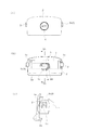
図1に自動車のグローブボックスのリッドロックとして構成された本発明の実施の形態を示す。リッドロックは、操作ハンドル2をベース1に回転操作自在に連結して形成される。
FIG. 1 shows an embodiment of the present invention configured as a lid lock of a glove box of an automobile. The lid lock is formed by connecting the
操作ハンドル2の下端裏面には全長にわたって指掛け部2aが膨隆され、さらに、裏面中央部にロック保持筒2bが形成される。ロック保持筒2bは両端に開放されており、このロック保持筒2b内に2個のロック部材3、3が回転および長手方向に移動自在に挿入される。
A finger-hanging
ロック部材3は、外周にカム溝3aを凹設した円筒カム部3bの一端から断面矩形のロック杆部3cを突出させた杆体であり、各々ロック杆部3c、3cをロック保持筒2bの開放端に向けた背向姿勢で収容される。ロック保持筒2bの内壁には円筒カム部3bのカム溝3aに移動自在に嵌合するカム突部2cが突設される。各ロック部材3は、ロック保持筒2bの中心部に収容される圧縮スプリング7によって、ロック杆部3cがロック保持筒2bから突出するロック位置に向けて付勢される。
The
上記ベース1は、リッドに固定される本体部の両端からヒンジ片1aを突出して形成され、ヒンジ片1aに開設された矩形開口1bにロック部材3のロック杆部3cが挿通する。
The
ロック装置をリッドに固定して操作ハンドル2に操作力を加えない状態で、ロック部のロック杆部3cはロック保持筒2bから突出したロック位置に保持される。この状態でロック杆部3cはグローブボックス側のストライク(図示せず)に係止し、リッドの閉塞状態が保持される。
In a state where the locking device is fixed to the lid and no operating force is applied to the
このロック状態から操作ハンドル2の指掛け部2aに指を掛けて手前側に引き出すと、ベース1に対して相対回転不能なロック部材3の円筒カム部3b周りに操作ハンドル2が空転する。円筒カム部3bと操作ハンドル2、すなわちロック保持筒2b内のカム突部2cとが相対回転すると、円筒カム部3bに軸方向駆動力が発生する。円筒カム部3bのカム溝3aは、カム突部2cの上述した方向の回転に対して円筒カムがロック保持筒2bの中心方向に移動するように設定されており、結果、ロック部材3は中心方向に並進移動してアンロック位置に移動する。アンロック位置においてロック杆部3cは上記ストライクとの係止位置から離脱するために、リッドの開放が可能になる。
When the finger is placed on the
操作ハンドル2を回転させた状態で操作力を解除すると、圧縮スプリング7の復元力によりロック部材3に突出方向の付勢力が作用し、カム溝3aがカム突部2cに押し付けられる。この結果、カム突部2cには、カム溝3aから回転方向の分力が発生し、ロック部材3のロック位置側への移動に伴って、操作ハンドル2は初期回転位置に復帰する。
When the operation force is released while the
上記操作ハンドル2への無制限な回転操作を規制するために、ロック装置には施錠部が設定される。構造を簡単にしてコスト低減を図るために、施錠部は、操作ハンドル2に形成されたプラグ保持筒2dにプラグ4を挿入して形成される。図3に示すように、プラグ4の後端部には、抜け止め用タンブラ4aが装着され、プラグ4をプラグ保持筒2d内に押し込むと、抜け止め用タンブラ4aはプラグ保持筒2d内の抜け止め突部2eに形成される斜面2fにより一旦プラグ4内に没入した後、図外の圧縮スプリングの復元力により突出位置に復帰し、以後、抜け止め突部2eに係止してプラグ保持筒2dからの脱離が規制される。
In order to restrict unrestricted rotational operation to the
プラグ4は、図外のタンブラを備えており、真正な解錠キー(図示せず)を使用することにより、施錠位置から解錠位置に回転操作することができる。
The
図3、4に示すように、プラグ4の後端にはロック用突部4bが突設されるとともに、ベース1の本体部には、前方に向けてロック段部1cが突設される。図4に示すように、プラグ4は図4(a)に示す解錠位置と、図4(b)の施錠位置との間で90°回転操作され、これに伴って、ロック用突部4bは、左右中心に対して線対称位置に移動する。一方、ロック段部1cは、プラグ4が施錠位置にあるときのロック用突部4bの下方に配置される。
As shown in FIGS. 3 and 4, a
したがってこの実施の形態において、プラグ4を施錠位置に回転させた状態では、プラグ4のロック用突部4bの下方への移動はロック段部1cにより規制されるために、図3(b)に示すように、ロック用突部4bの下方への移動を伴う操作ハンドル2の回転が規制される。これに対し、プラグ4が解錠位置にあるときには、ロック用突部4bの下方への経路がロック段部1cに閉塞されないために、操作ハンドル2への回転操作が許容される。
Therefore, in this embodiment, when the
上記ベース1には、施解錠位置においてプラグ4の後端を押圧するプラグ押圧部5が形成される。図1に示すように、プラグ押圧部5は、施解錠位置におけるプラグ4のロック用突部4bに対応して横長板状に形成され、ロック段部1cの上端を基端として上方に張り出される。このプラグ押圧部5の前面は、図3(b)に示すように、上方に行くに従って漸次前方に傾く傾斜面5aとされている。
The
したがってこの実施の形態において、操作ハンドル2が回転位置から復帰すると、プラグ4のロック用突部4bがロック段部1cの側方を通って上方領域に進入する。ロック用突部4bは上方への移動に伴ってやがてプラグ押圧部5の傾斜面5aに当接し、片持梁状に形成されて弾性変形可能なプラグ押圧部5はやや弾性変形しながらこのロック用突部4bを受容する。
Therefore, in this embodiment, when the operation handle 2 returns from the rotational position, the locking
操作ハンドル2の復帰回転は、圧縮スプリング7による操作ハンドル2の復帰力とロック用突部4bに対するプラグ押圧部5の傾斜面5aからの抵抗力とが釣り合う位置で停止する。この停止位置において、プラグ4は前方に押し付けられてベース1の抜け止め突部2e等の前方へのストッパ壁に圧接し、がたつきが防止される。この状態から操作ハンドル2を回転させると、プラグ押圧部5の弾性変形、ストッパ壁への圧接状態が解除され、再び初期回転位置に復帰した際に、新たな圧接状態が発生する。
The return rotation of the operation handle 2 stops at a position where the return force of the operation handle 2 by the
また、図3(c)、(d)に示すように、プラグ押圧部5、またはプラグ4のロック用突部4b先端に小突起4cを形成するとともに、他方に、上記小突起4cが嵌合する凹部4dを形成した場合には、操作ハンドル2が復帰した際の節度感を発生させることができる。
3 (c) and 3 (d), a
さらに、図3(c)、(d)においては、ロック用突部4bの上下移動に伴って小突起4cと凹部4dとが嵌合するように形成し、操作ハンドル2の初期回転位置への復帰時に節度感を発生するように構成されるが、この小突起4cと凹部4dとをロック用突部4bの側方への移動に伴って嵌合するクリック機構6として構成すると、プラグ4を施解錠間で回転操作すると、小突起4cが凹部4dに弾性的に嵌合して節度感が発生する。
Further, in FIGS. 3C and 3D, the
また、以上においては、プラグ押圧部5はロック段部1cから上方に向けて形成されているが、図5に示すように、下方に自由端縁を向けた姿勢で形成することができる。この場合、傾斜面5aは、プラグ押圧部5の下端縁に形成され、ロック用突部4bの上方への移動に干渉する。
In the above description, the
1 ベース
2 操作ハンドル
3 ロック部材
4 プラグ
5 プラグ押圧部
6 クリック機構
DESCRIPTION OF
Claims (4)
操作ハンドルへの回転操作によりロック、アンロック位置間を駆動されるロック部材と、
操作ハンドルとベースとのいずれか一方に回転操作可能に装着され、施錠回転位置において他方に係止して操作ハンドルを初期回転位置に拘束するプラグとを備えたロック装置であって、
前記操作ハンドルにプラグが装着される場合のベース、あるいは、前記ベースにプラグが装着される場合の操作ハンドルには、操作ハンドルの回転操作位置から初期回転位置への復帰動作に伴ってプラグの後端部に干渉し、操作ハンドルが初期回転位置にあるときにプラグを前方に押し付けるプラグ押圧部が設けられるロック装置。 An operation handle coupled to the base so as to be freely rotatable between an initial rotation position and a rotation operation position;
A locking member that is driven between a lock and unlock position by a rotation operation to the operation handle;
A locking device including a plug that is rotatably mounted on one of the operation handle and the base and that locks the other in the locked rotation position to restrain the operation handle at the initial rotation position;
The base when the plug is attached to the operation handle or the operation handle when the plug is attached to the base is connected to the back of the plug in accordance with the return operation from the rotation operation position of the operation handle to the initial rotation position. A locking device provided with a plug pressing portion that interferes with the end portion and presses the plug forward when the operation handle is in the initial rotation position.
前記プラグ押圧部は、復帰付勢力によりプラグへの押し付け力を得る請求項1記載のロック装置。 A return urging force toward the initial rotation position is applied to the operation handle,
The locking device according to claim 1, wherein the plug pressing portion obtains a pressing force against the plug by a return biasing force.
Wherein the contact portion between the plug pressing portion and the plug rear end part, whereas one plug unlocking, or according to any one of claims 1 to click mechanism for moderation stop plug is formed 3 in both positions Locking device.
Priority Applications (1)
| Application Number | Priority Date | Filing Date | Title |
|---|---|---|---|
| JP2007310722A JP5220397B2 (en) | 2007-11-30 | 2007-11-30 | Locking device |
Applications Claiming Priority (1)
| Application Number | Priority Date | Filing Date | Title |
|---|---|---|---|
| JP2007310722A JP5220397B2 (en) | 2007-11-30 | 2007-11-30 | Locking device |
Publications (2)
| Publication Number | Publication Date |
|---|---|
| JP2009133135A JP2009133135A (en) | 2009-06-18 |
| JP5220397B2 true JP5220397B2 (en) | 2013-06-26 |
Family
ID=40865262
Family Applications (1)
| Application Number | Title | Priority Date | Filing Date |
|---|---|---|---|
| JP2007310722A Expired - Fee Related JP5220397B2 (en) | 2007-11-30 | 2007-11-30 | Locking device |
Country Status (1)
| Country | Link |
|---|---|
| JP (1) | JP5220397B2 (en) |
Family Cites Families (4)
| Publication number | Priority date | Publication date | Assignee | Title |
|---|---|---|---|---|
| JPH08189237A (en) * | 1994-12-29 | 1996-07-23 | Nifco Inc | Lock mechanism of cover |
| JP3363035B2 (en) * | 1996-07-30 | 2003-01-07 | 株式会社アルファ | Lid locking device |
| JP4699160B2 (en) * | 2005-10-03 | 2011-06-08 | 株式会社パイオラックス | Side lock device |
| JP2007285021A (en) * | 2006-04-18 | 2007-11-01 | Kojima Press Co Ltd | Locking device for glove box |
-
2007
- 2007-11-30 JP JP2007310722A patent/JP5220397B2/en not_active Expired - Fee Related
Also Published As
| Publication number | Publication date |
|---|---|
| JP2009133135A (en) | 2009-06-18 |
Similar Documents
| Publication | Publication Date | Title |
|---|---|---|
| JP5288314B2 (en) | Vehicle door latch device | |
| EP3075929B1 (en) | Door handle device for vehicle | |
| CN217581693U (en) | Door lock device | |
| JP2015511669A (en) | Locking device having a claw portion having a plurality of parts | |
| JP5295074B2 (en) | Lock device and door using the same | |
| JP4926875B2 (en) | Cylinder lock, clutch device, and unlocking device equipped with these cylinder lock and clutch device | |
| JP6538409B2 (en) | Vehicle steering wheel | |
| JP6618861B2 (en) | Door lock device | |
| JP2005120681A (en) | Door lock device for vehicle | |
| JP6477035B2 (en) | Door handle device | |
| JP4345432B2 (en) | Vehicle door latch mechanism | |
| JP5220397B2 (en) | Locking device | |
| JP5005459B2 (en) | Cylinder lock and unlocking device having the same | |
| JP4987778B2 (en) | Vehicle door handle | |
| JP7778638B2 (en) | Vehicle handle | |
| JP2023146798A (en) | door latch device | |
| JP6135281B2 (en) | Door latch device for automobile | |
| JP4484170B2 (en) | Anti-panic mechanism for vehicle door latch device | |
| JP4850608B2 (en) | Cylinder lock | |
| JP6708489B2 (en) | Door lock device | |
| EP4474602A1 (en) | Door latch device | |
| JP6089299B2 (en) | Door latch device for automobile | |
| JP4233976B2 (en) | Vehicle door lock device | |
| EP4556662A1 (en) | Door latch device | |
| JP4573853B2 (en) | Push button cylinder lock |
Legal Events
| Date | Code | Title | Description |
|---|---|---|---|
| A621 | Written request for application examination |
Free format text: JAPANESE INTERMEDIATE CODE: A621 Effective date: 20100317 |
|
| A977 | Report on retrieval |
Free format text: JAPANESE INTERMEDIATE CODE: A971007 Effective date: 20120125 |
|
| A131 | Notification of reasons for refusal |
Free format text: JAPANESE INTERMEDIATE CODE: A131 Effective date: 20120131 |
|
| A521 | Written amendment |
Free format text: JAPANESE INTERMEDIATE CODE: A523 Effective date: 20120402 |
|
| A521 | Written amendment |
Free format text: JAPANESE INTERMEDIATE CODE: A821 Effective date: 20120403 |
|
| A131 | Notification of reasons for refusal |
Free format text: JAPANESE INTERMEDIATE CODE: A131 Effective date: 20120424 |
|
| A521 | Written amendment |
Free format text: JAPANESE INTERMEDIATE CODE: A821 Effective date: 20120619 Free format text: JAPANESE INTERMEDIATE CODE: A523 Effective date: 20120619 |
|
| A131 | Notification of reasons for refusal |
Free format text: JAPANESE INTERMEDIATE CODE: A131 Effective date: 20120807 |
|
| A521 | Written amendment |
Free format text: JAPANESE INTERMEDIATE CODE: A523 Effective date: 20120829 Free format text: JAPANESE INTERMEDIATE CODE: A821 Effective date: 20120829 |
|
| TRDD | Decision of grant or rejection written | ||
| A01 | Written decision to grant a patent or to grant a registration (utility model) |
Free format text: JAPANESE INTERMEDIATE CODE: A01 Effective date: 20130226 |
|
| A61 | First payment of annual fees (during grant procedure) |
Free format text: JAPANESE INTERMEDIATE CODE: A61 Effective date: 20130306 |
|
| FPAY | Renewal fee payment (event date is renewal date of database) |
Free format text: PAYMENT UNTIL: 20160315 Year of fee payment: 3 |
|
| R150 | Certificate of patent or registration of utility model |
Ref document number: 5220397 Country of ref document: JP Free format text: JAPANESE INTERMEDIATE CODE: R150 |
|
| R250 | Receipt of annual fees |
Free format text: JAPANESE INTERMEDIATE CODE: R250 |
|
| R250 | Receipt of annual fees |
Free format text: JAPANESE INTERMEDIATE CODE: R250 |
|
| R250 | Receipt of annual fees |
Free format text: JAPANESE INTERMEDIATE CODE: R250 |
|
| R250 | Receipt of annual fees |
Free format text: JAPANESE INTERMEDIATE CODE: R250 |
|
| R250 | Receipt of annual fees |
Free format text: JAPANESE INTERMEDIATE CODE: R250 |
|
| LAPS | Cancellation because of no payment of annual fees |