JP5219528B2 - Radio receiving apparatus and radio receiving method - Google Patents
Radio receiving apparatus and radio receiving method Download PDFInfo
- Publication number
- JP5219528B2 JP5219528B2 JP2008011826A JP2008011826A JP5219528B2 JP 5219528 B2 JP5219528 B2 JP 5219528B2 JP 2008011826 A JP2008011826 A JP 2008011826A JP 2008011826 A JP2008011826 A JP 2008011826A JP 5219528 B2 JP5219528 B2 JP 5219528B2
- Authority
- JP
- Japan
- Prior art keywords
- symbol
- frame
- training
- synchronization
- sequence
- Prior art date
- Legal status (The legal status is an assumption and is not a legal conclusion. Google has not performed a legal analysis and makes no representation as to the accuracy of the status listed.)
- Expired - Fee Related
Links
Images


Landscapes
- Time-Division Multiplex Systems (AREA)
- Synchronisation In Digital Transmission Systems (AREA)
Description
本発明は、無線受信装置および無線受信方法に関する。 The present invention relates to a wireless reception device and a wireless reception method.
物理的に異なる場所に設置された各通信局が、特定の割り当てられた時間帯のみ信号を送出し通信を行う方式は、時分割多元接続通信(Time Division Multiple Access:TDMA)方式と呼ばれる。TDMAを用いる無線通信システムとしては、衛星通信システム(Dyanet)や(例えば、非特許文献1参照)、簡易型携帯電話システムPHS(例えば、非特許文献2参照)などが知られている。また、通信時間帯の割り当てを必要としない自立分散型の多元接続通信方式として、CSMA(Carrier Sense Multiple Access/Collision Avoidance)方式がある。IEEE802.11に準拠した無線LANシステム(例えば、非特許文献3参照)などは、このCSMA/CA方式を採用している。 A system in which each communication station installed in a physically different location transmits a signal only during a specific assigned time zone and performs communication is called a time division multiple access (TDMA) system. As a wireless communication system using TDMA, a satellite communication system (Dynet), (for example, refer to Non-Patent Document 1), a simplified mobile phone system PHS (for example, refer to Non-Patent Document 2), and the like are known. Further, as an independent distributed multiple access communication method that does not require allocation of a communication time zone, there is a CSMA (Carrier Sense Multiple Access / Collision Avoidance) method. A wireless LAN system compliant with IEEE802.11 (see, for example, Non-Patent Document 3) employs this CSMA / CA method.
これらTDMAシステムやCSMA/CAに共通しているのは、いずれも時間軸上で無線伝送信号が多重化されている点である。時分割通信を実現するためには、各通信局から送信される無線伝送信号は間欠的にならざるを得ない。すなわち、バースト通信を行うことが必須となる。無線バースト信号を受信して情報を取り出すためには、シンボルタイミング同期、搬送波周波数同期、搬送波位相同期(伝搬路変動補償を含む)、フレーム同期といった各種同期技術が必要となる(例えば、非特許文献4参照)。 What is common to these TDMA systems and CSMA / CA is that radio transmission signals are multiplexed on the time axis. In order to implement time division communication, the radio transmission signal transmitted from each communication station must be intermittent. That is, it is essential to perform burst communication. In order to extract information by receiving a radio burst signal, various synchronization techniques such as symbol timing synchronization, carrier frequency synchronization, carrier phase synchronization (including propagation path fluctuation compensation), and frame synchronization are required (for example, non-patent documents). 4).
これらの各種同期を実現するためには、無線バースト伝送信号に伝送したい情報信号系列だけでなく、各種同期を確立するための既知の信号系列(トレーニング信号)を時間軸上で多重化する方法が知られている。 In order to realize these various synchronizations, there is a method of multiplexing not only an information signal sequence to be transmitted to a radio burst transmission signal but also a known signal sequence (training signal) for establishing various synchronizations on a time axis. Are known.
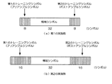
図9(a)、(b)は、従来技術による、Dyanetや、PHSに代表されるシステム(以下、第1の従来システム)のバースト構成を示す概念図である。Dyanetでは、シンボルタイミング同期のためのBTR(Bit Timing Recovery)シンボル、搬送波周波数同期のためのCR(Carrier Recovery)シンボル、フレーム同期のためのUW(Unique Word)シンボルがトレーニング信号として用いられている(非特許文献1)。同じくPHSでも、シンボルタイミング同期および搬送波周波数同期のためのPR(Preamble)シンボル、フレーム同期のためのUWシンボルが用いられている(非特許文献2)。 FIGS. 9A and 9B are conceptual diagrams showing a burst configuration of a system represented by Dynanet and PHS (hereinafter referred to as a first conventional system) according to the prior art. In Dynet, BTR (Bit Timing Recovery) symbols for symbol timing synchronization, CR (Carrier Recovery) symbols for carrier frequency synchronization, and UW (Unique Word) symbols for frame synchronization are used as training signals ( Non-patent document 1). Similarly in PHS, PR (Preamble) symbols for symbol timing synchronization and carrier frequency synchronization and UW symbols for frame synchronization are used (Non-Patent Document 2).
このように、第1の従来システムでは、図9(a)、(b)に示すように、シンボルタイミング同期および搬送波周波数同期に必要なトレーニング信号とフレーム同期のためのトレーニング信号とを分離する必要がある。このため、トレーニング信号によるオーバーヘッドが大きくなり、特に情報シンボル信号部分が短いバーストに対して伝送効率が劣化するという問題がある。 Thus, in the first conventional system, as shown in FIGS. 9A and 9B, it is necessary to separate the training signal required for symbol timing synchronization and carrier frequency synchronization from the training signal for frame synchronization. There is. For this reason, the overhead due to the training signal is increased, and there is a problem that the transmission efficiency is deteriorated particularly for a burst having a short information symbol signal portion.
図10は、第1の従来システムの受信同期処理を示す機能ブロック図である。第1の従来システムの受信同期処理では、クロック位相誤差推定10、シンボルタイミング同期確立11、搬送波周波数オフセット推定12、搬送波周波数同期確立13、UW相関検出14、及びフレーム同期確立15を行う。図10に示すように、これらの3つの受信同期処理、すなわち、シンボルタイミング同期確立11、搬送波周波数同期確立13、フレーム同期確立15を別の演算処理で行うことが必要であり、さらに各々のブロックで自己相関演算や、離散フーリエ変換(Discrete Fourier Transform:DFT)など負荷の大きい演算を必要とするため、受信処理ベースバンド回路の回路規模や、消費電力などが増大するという問題がある。
FIG. 10 is a functional block diagram showing reception synchronization processing of the first conventional system. In the reception synchronization processing of the first conventional system, clock
さらに、第1の従来システムでは、同期検波を行うために、搬送波位相同期が必要である。第1の従来システムでは、逆変調方式などに代表される搬送波再生方式を用いて搬送波位相同期を確立する。位相不確定性については、無変調信号であるCRを用いて除去するか、あるいは位相不確定性が存在しても復調が可能となるように、変調時に情報シンボルの差動符号化を行う。 Furthermore, the first conventional system requires carrier phase synchronization in order to perform synchronous detection. In the first conventional system, carrier phase synchronization is established using a carrier recovery method represented by an inverse modulation method or the like. The phase uncertainty is removed using CR, which is an unmodulated signal, or information symbols are differentially encoded during modulation so that demodulation is possible even when phase uncertainty exists.
また、第1の従来システムは、いずれも逐次復調方式であるが、搬送波周波数同期を確立し搬送波再生を行うには、複数のバースト信号を繰り返し参照して引き込むことが必要であり、1バースト時間で引き込むことはできない。また、フレーム同期を行うには、UWのビット判定が必要であり、予め搬送波周波数同期が高精度に取れている必要がある。 In addition, the first conventional system is a sequential demodulation method, but in order to establish carrier frequency synchronization and perform carrier recovery, it is necessary to repeatedly refer to a plurality of burst signals and draw one burst time. It cannot be pulled in. Further, in order to perform frame synchronization, UW bit determination is required, and carrier frequency synchronization needs to be obtained with high accuracy in advance.
すなわち、第1の従来システムでは、以下の3つの問題点を有している。
(A1)各受信同期処理のために、それぞれ専用のトレーニング信号を別々に用意する必要があるため、オーバーヘッドが大きくなり、特に情報シンボル信号部分が短い場合に伝送効率が劣化する。
(A2)各受信同期処理を異なる信号処理で行うため、演算量が多く、受信装置の回路規模および消費電力が増大する。
(A3)各受信同期を1受信バースト内で確立することができない。
That is, the first conventional system has the following three problems.
(A1) Since it is necessary to prepare dedicated training signals separately for each reception synchronization process, overhead increases, and transmission efficiency deteriorates particularly when the information symbol signal portion is short.
(A2) Since each reception synchronization process is performed by different signal processing, the amount of calculation is large, and the circuit scale and power consumption of the reception apparatus increase.
(A3) Each reception synchronization cannot be established within one reception burst.
上記(A3)を解決するバースト無線伝送システムとして、IEEE802.11a(以下、第2の従来システム)がある(上記非特許文献3)。IEEE802.11aは、マルチキャリア伝送方式である直交周波数分割多重(Orthogonal Frequency Division Multiplexing)を適用したIEEE802.11準拠無線LANの規格の1つである。 As a burst wireless transmission system that solves the above (A3), there is IEEE802.11a (hereinafter referred to as a second conventional system) (Non-Patent Document 3). IEEE802.11a is one of IEEE802.11 compliant wireless LAN standards to which orthogonal frequency division multiplexing (Orthogonal Frequency Division Multiplexing), which is a multicarrier transmission method, is applied.
図11は、第2の従来システムのバースト構成を示す概念図である。第2の従来システムでは、各受信同期処理を実現するために、シンボルタイミング同期、搬送波周波数同期、フレーム同期用のショートプリアンブル(ShortPR)と、伝搬路歪み補償用のロングプリアンブル(LongPR)との2種類のトレーニング信号がバースト先頭に配置される。 FIG. 11 is a conceptual diagram showing a burst configuration of the second conventional system. In the second conventional system, in order to realize each reception synchronization process, a short preamble (ShortPR) for symbol timing synchronization, carrier frequency synchronization, and frame synchronization, and a long preamble (LongPR) for propagation path distortion compensation are used. Types of training signals are placed at the beginning of the burst.
また、図12は、第2の従来システムの受信同期処理示す機能ブロック図である。ショートプリアンブル信号部に対し、スライディング相互相関演算20により、相互相関演算を行い、ピーク検出21により、相互相関値のピーク位置を検出し、フレーム同期確立シンボルタイミング同期確立22により、シンボルタイミング同期およびフレーム同期を確立し、自己相関演算23及び位相検出24により、自己相関値の位相成分を検出して、搬送波周波数同期確立25により、搬送波周波数同期を確立する。搬送波周波数同期には、ロングプリアンブル信号部を用いることもできる。
FIG. 12 is a functional block diagram showing reception synchronization processing of the second conventional system. A cross-correlation operation is performed on the short preamble signal portion by a
第2の従来システムでは、受信バースト信号に含まれるトレーニング信号情報を蓄積し相関演算を行うことによって各受信同期を確立する。そのため、1受信バースト内で各受信同期が確立可能であり、第1の従来システムの問題点(A3)を解決できる。 In the second conventional system, each reception synchronization is established by accumulating training signal information included in the received burst signal and performing a correlation calculation. Therefore, each reception synchronization can be established within one reception burst, and the problem (A3) of the first conventional system can be solved.
しかし、第2の従来システムでは、ショートプリアンブルが短い時間周期とならざるを得ないことから、擬似雑音(Pseudo Noise:PN)系列を用いた場合と比較して、自己相関の直交性が劣化する。そのため、相互相関値のピーク検出精度がPN系列を用いた場合より劣化し、シンボルタイミング同期およびフレーム同期精度が劣化するという問題がある。 However, in the second conventional system, since the short preamble has to be a short time period, the orthogonality of the autocorrelation is deteriorated as compared with the case where a pseudo noise (PN) sequence is used. . Therefore, there is a problem that the peak detection accuracy of the cross-correlation value is deteriorated as compared with the case where the PN sequence is used, and the symbol timing synchronization and the frame synchronization accuracy are deteriorated.
また、第2の従来システムでは、送受信装置間の搬送波周波数オフセットの影響によってショートプリアンブル信号部内での位相回転量が無視できないような低速通信の場合、相互相関値の積和演算において各項の位相が回転してしまい、所望サンプル位置で相関値がピークを取らない可能性がある。このとき、シンボルタイミングおよびフレーム同期制度は劣化する。 In the second conventional system, in the case of low-speed communication in which the amount of phase rotation in the short preamble signal part cannot be ignored due to the influence of the carrier frequency offset between the transmitting and receiving apparatuses, the phase of each term is calculated in the product-sum operation of the cross-correlation values. May rotate and the correlation value may not take a peak at the desired sample position. At this time, the symbol timing and the frame synchronization system deteriorate.
すなわち、第2の従来システムは、(A3)の問題を解決してはいるものの、以下の4つの問題点を有している。
(B1)各受信同期処理のために、それぞれ専用のトレーニング信号を別々に用意する必要があるため、オーバーヘッドが大きくなり、特に情報シンボル信号部分が短い場合に伝送効率が劣化する。
(B2)各受信同期処理を異なる信号処理で行うため、演算量が多く、受信装置の回路規模および消費電力が増大する。
(B4)ショートプリアンブルがPN系列とならないため、PN系列を用いた場合と比較してシンボルタイミング同期およびフレーム同期精度が劣化する。
(B5)低速通信においては、ショートプリアンブル内での位相が回転し、シンボルタイミング同期およびフレーム同期精度が劣化する。
That is, the second conventional system has the following four problems although it solves the problem (A3).
(B1) Since dedicated training signals need to be prepared separately for each reception synchronization process, overhead increases, and transmission efficiency deteriorates particularly when the information symbol signal portion is short.
(B2) Since each reception synchronization process is performed by different signal processing, the amount of calculation is large, and the circuit scale and power consumption of the reception apparatus increase.
(B4) Since the short preamble does not become a PN sequence, symbol timing synchronization and frame synchronization accuracy are deteriorated as compared with the case where a PN sequence is used.
(B5) In low-speed communication, the phase in the short preamble rotates, and symbol timing synchronization and frame synchronization accuracy deteriorate.
上記(B4)および(B5)の問題を解決するため、フレーム同期用にUWの差動符号化を用いて、相互相関演算を用いたピーク検出前に遅延検波を行うフレーム同期方式(以下、第3の従来方式)が考案されている(例えば、非特許文献5参照)。 In order to solve the problems (B4) and (B5) described above, a frame synchronization method (hereinafter referred to as the first) that performs differential detection before peak detection using cross-correlation calculation using UW differential encoding for frame synchronization. 3) (see, for example, Non-Patent Document 5).
図13は、第3の従来方式を用いた無線受信装置の構成を示すブロック図である。なお、図13では、デジタル信号処理を行うベースバンド処理部のみを示し、前には無線信号受信のための空中線および無線部が接続される。 FIG. 13 is a block diagram showing a configuration of a wireless reception apparatus using the third conventional method. FIG. 13 shows only a baseband processing unit that performs digital signal processing, and an antenna for receiving a radio signal and a radio unit are connected before.
アナログ受信バースト信号S300は、A/D変換器301によってデジタル受信バースト信号S301に変換される。A/D変換後のデジタル受信バースト信号S301は、受信フィルタ302に入力され、受信フィルタ処理後の受信バースト信号S302が出力される。受信フィルタ処理後の受信バースト信号S302は、シンボルタイミング同期回路303によってシンボルタイミングの検出および同期が行われ、受信バーストシンボル系列S303が出力される。
The analog reception burst signal S300 is converted into a digital reception burst signal S301 by the A /
受信バーストシンボル系列S303は、搬送波周波数同期回路304に入力され、搬送波周波数同期後の受信バーストシンボル系列S304が出力される。搬送波周波数同期後の受信バーストシンボル系列S304は、フレーム検出回路305に入力され、フレーム位置情報S305が出力される。受信バーストシンボル系列S304は、フレーム同期回路306に入力されフレーム位置情報S305に基づいてフレーム同期が確立され、受信バーストシンボル系列S306が出力される。フレーム同期確立後の受信バーストシンボル系列S306は、シンボル識別回路307で情報シンボルからデータビット系列に変換され、受信データ信号S307として出力される。
Reception burst symbol sequence S303 is input to carrier
図14は、図13に示した無線受信装置におけるフレーム検出回路305の構成を示すブロック図である。シンボルタイミングおよび搬送波周波数同期確立後の受信バーストシンボル系列S304は、トレーニングシンボル抽出回路401に入力され、受信トレーニングシンボル区間に相当するシンボル系列S401が入力シンボル毎に出力される。受信トレーニングシンボル系列S401は、1シンボル遅延回路402に入力され、1シンボル遅延後の受信トレーニングシンボル系列S402が出力される。1シンボル遅延前の受信トレーニングシンボル系列S401および1シンボル遅延後の受信トレーニングシンボル系列S402は、複素共役乗算回路403に入力されることによって差動復号化、すなわち遅延検波される。遅延検波後の受信トレーニングシンボル系列S403が出力される。
FIG. 14 is a block diagram showing a configuration of the
遅延検波後の受信トレーニングシンボル系列S403は、ビット判定回路(遅延検波)404に入力され、ビット判定(シンボル識別)され、ビット判定後の受信フレーム同期符号系列S404が出力される。一方、同期符号系列生成回路405は、既知のフレーム同期符号系列S405を生成する。受信フレーム同期符号系列S404および既知のフレーム同期符号系列S405は、相互相関計算回路(ビット演算)406に入力され、相互相関値S406が出力される。受信バースト信号の入力シンボル毎に入力される相互相関値S406は、相関ピーク検出回路407に入力され、相関値が最大となるシンボル位置をフレーム位置として検出し、フレーム位置情報S305が出力される。
The received training symbol sequence S403 after delay detection is input to a bit determination circuit (delay detection) 404, subjected to bit determination (symbol identification), and a received frame synchronization code sequence S404 after bit determination is output. On the other hand, the synchronization code
第3の従来方式は、前述した第1の従来システムと同様に、フレーム同期のためにUWをトレーニング信号として含む必要がある。UWの符号系列としてPN系列のような自己相関の直交性に優れた符号系列を用いることが可能であるため、第2の従来システムの(B4)の問題点を解決できる。また、UWの符号系列を遅延検波することによって送受信装置間の搬送波周波数オフセットの影響を低減できるため、(B5)の問題点も解決できる。 As in the first conventional system described above, the third conventional system needs to include UW as a training signal for frame synchronization. Since a code sequence having excellent autocorrelation orthogonality such as a PN sequence can be used as the UW code sequence, the problem (B4) of the second conventional system can be solved. In addition, since the influence of the carrier frequency offset between the transmitting and receiving apparatuses can be reduced by delay detection of the UW code sequence, the problem (B5) can also be solved.
但し、第3の従来方式は、また、フレーム位置の検出にはシンボルタイミング同期確立後の遅延検波およびビット判定が必要であるため、図9に示すバースト構成を有する第1の従来システム同様に、UWの他にシンボルタイミング同期および搬送波周波数同期を確立するためのトレーニングシンボル系列を備える必要がある。 However, since the third conventional method requires delay detection and bit determination after the symbol timing synchronization is established in order to detect the frame position, as in the first conventional system having the burst configuration shown in FIG. In addition to UW, it is necessary to provide a training symbol sequence for establishing symbol timing synchronization and carrier frequency synchronization.
したがって、前述した第1の従来システムの(A3)の問題点を解決した上で、第3の従来方式を適用したとしても、第2の従来システムの(B1)および(B2)の問題点を解決することはできない。
上述したように、第1および第2の従来システムや、第3の従来方式では、バースト無線伝送を行う上でオーバーヘッドとなるトレーニングシンボルによる伝送効率の劣化、回路規模や、消費電力の増大、低速通信におけるシンボルタイミング同期や、フレーム同期精度の劣化といった問題を解決することができない、という問題があった。 As described above, in the first and second conventional systems and the third conventional system, transmission efficiency deteriorates due to an overhead training symbol in performing burst radio transmission, circuit scale, power consumption increases, and low speed. There has been a problem that problems such as symbol timing synchronization in communication and deterioration of frame synchronization accuracy cannot be solved.
本発明は、このような事情を考慮してなされたものであり、その目的は、無線バースト通信においてオーバーヘッドによる伝送効率劣化を低減することができ、また、信号処理演算量を低減し、高精度なバースト同期を実現することができる無線受信装置および無線受信方法を提供することにある。 The present invention has been made in consideration of such circumstances, and the object thereof is to reduce transmission efficiency degradation due to overhead in wireless burst communication, and to reduce the amount of signal processing computation, thereby achieving high accuracy. It is an object of the present invention to provide a radio reception apparatus and radio reception method that can realize burst synchronization.
上述した課題を解決するために、本発明は、差動符号化された同期符号系列をトレーニングシンボルとし、該トレーニングシンボルと情報シンボルとから構成された無線バースト信号を受信する無線受信装置において、前記無線バースト信号に含まれるトレーニングシンボル系列を用いて、オーバーサンプリングされた受信バースト信号系列からフレーム・シンボルタイミングを検出するフレーム・シンボルタイミング検出手段と、前記フレーム・シンボルタイミング検出手段で検出されたフレーム・シンボルタイミングに基づいて、受信バーストシンボル系列を抽出するフレーム・シンボルタイミング同期手段と、前記フレーム・シンボルタイミング同期手段で抽出された受信バーストシンボル系列から受信情報シンボル系列を抽出してシンボル識別を行うシンボル識別手段とを備え、前記フレーム・シンボルタイミング検出手段は、前記トレーニングシンボル区間に相当する受信信号サンプルを入力サンプル毎に出力するトレーニングシンボル部サンプル抽出手段と、前記トレーニングシンボル部サンプル抽出手段から出力された受信トレーニングシンボル部信号サンプルを1〜n(nは1以上の整数)シンボル時間相当のサンプル時間遅延させて出力するn個の遅延手段と、前記トレーニングシンボル部サンプル抽出手段から出力された受信トレーニングシンボル部信号サンプル系列と、前記n個の遅延手段から出力された受信トレーニングシンボル部信号サンプル系列との複素共役乗算を行い、受信トレーニングシンボル部サンプル系列のそれぞれ1〜nシンボル時間差動復号化を行うn個の複素共役乗算手段と、前記n個の複素共役乗算手段から出力されたトレーニングシンボル部信号サンプルのダウンサンプリングを行い、差動復号化された受信トレーニングシンボル系列を抽出するn個のダウンサンプリング手段と、既知のトレーニングシンボル系列を生成するトレーニングシンボル生成手段と、前記トレーニングシンボル生成手段から出力されるトレーニングシンボル系列の1〜nシンボル時間差動復号化を行うn個の差動復号化手段と、前記差動復号化された受信トレーニングシンボル系列と、前記差動復号化された既知のトレーニングシンボル系列との相互相関値を計算し、入力サンプル毎に出力するn個の相互相関値計算手段と、前記n個の相互相関値計算手段から出力されたn個の相互相関値に基づいて、前記相互相関値が最大となるサンプル位置をフレーム・シンボルタイミング位置として検出する相関ピーク検出手段とを備えることを特徴とする無線受信装置である。 In order to solve the above-described problem, the present invention provides a radio receiving apparatus that receives a radio burst signal composed of a training symbol and an information symbol using a differentially-encoded synchronization code sequence as a training symbol. Frame symbol timing detection means for detecting frame symbol timing from an oversampled received burst signal sequence using a training symbol series included in a radio burst signal, and a frame detected by the frame symbol timing detection means Based on the symbol timing, a frame / symbol timing synchronization unit for extracting a received burst symbol sequence, and a received information symbol sequence is extracted from the received burst symbol sequence extracted by the frame / symbol timing synchronization unit. A symbol identifying means for performing a volume identification, wherein the frame symbol timing detecting means outputs a training symbol portion sample extracting means for outputting a received signal sample corresponding to the training symbol section for each input sample, and the training symbol portion sample. N delay means for outputting the received training symbol part signal samples output from the extraction means with a sample time delay equivalent to 1 to n (n is an integer of 1 or more) symbol time, and the training symbol part sample extracting means A complex conjugate multiplication of the output received training symbol part signal sample series and the received training symbol part signal sample series output from the n delay means is performed, and 1 to n symbol times of each of the received training symbol part sample series are obtained. Differential N complex conjugate multiplication means for performing encoding, and n for extracting the training symbol part signal sample that is differentially decoded by down-sampling the training symbol portion signal samples output from the n complex conjugate multiplication means Down-sampling means, training symbol generating means for generating a known training symbol series, and n differentials for 1-n symbol time differential decoding of the training symbol series output from the training symbol generating means A cross-correlation value between the decoding means, the differentially decoded received training symbol sequence, and the differentially decoded known training symbol sequence is calculated, and n cross-correlations output for each input sample And n cross-correlation values output from the n cross-correlation value calculation means. Zui and the cross-correlation value is a radio receiving apparatus, characterized in that it comprises a correlation peak detection means for detecting a frame symbol timing position sample position with the maximum.
本発明は、上記の発明において、前記フレーム・シンボルタイミング検出手段は、前記n個の相互相関値計算手段から出力されたn個の相互相関値に対し、各シンボル遅延時間に対応して位相補償を行う位相補償手段と、前記位相補償手段から出力されたn個の位相補償後相互相関値の和を計算する和算手段と、をさらに備え、前記相関ピーク検出手段は、前記和算手段から前記相互相関値が最大となるサンプル位置をフレーム・シンボルタイミング位置として検出することを特徴とする。 The present invention, in the above invention, the frame symbol timing detection means, before Symbol of n to n-number of cross-correlation values output from the correlation value calculation means, the phase corresponding to each symbol delay time Phase compensation means for performing compensation, and summing means for calculating the sum of the n phase-compensated cross-correlation values output from the phase compensation means , wherein the correlation peak detecting means comprises the summing means. the cross-correlation value is characterized and Turkey be detected as a frame symbol timing position sample position with the maximum of.
本発明は、上記の発明において、前記フレーム・シンボルタイミング検出手段は、さらに搬送波周波数の推定を行い、前記フレーム・シンボルタイミング同期手段は、さらに搬送波周波数同期を行い、前記相関ピーク検出手段は、さらに前記フレーム・シンボルタイミング位置の相互相関値の位相成分から搬送波周波数を推定し、前記フレーム・シンボルタイミング同期手段は、さらに搬送波周波数同期を行うことを特徴とする。 According to the present invention, in the above invention, the frame / symbol timing detection unit further estimates a carrier frequency, the frame / symbol timing synchronization unit further performs carrier frequency synchronization, and the correlation peak detection unit further includes A carrier frequency is estimated from a phase component of a cross-correlation value of the frame / symbol timing position, and the frame / symbol timing synchronization means further performs carrier frequency synchronization.
本発明は、上記の発明において、前記フレーム・シンボルタイミング検出手段は、さらに搬送波周波数の推定を行い、前記フレーム・シンボルタイミング同期手段は、さらに搬送波周波数同期を行い、前記相関ピーク検出手段は、さらに前記フレーム・シンボルタイミング位置の和算前の相互相関値の一部あるいは全てを用いて、その位相成分から搬送波周波数を推定し、前記フレーム・シンボルタイミング同期手段は、フレーム・シンボルタイミングだけでなく搬送波周波数同期を行うことを特徴とする。 According to the present invention, in the above invention, the frame / symbol timing detection unit further estimates a carrier frequency, the frame / symbol timing synchronization unit further performs carrier frequency synchronization, and the correlation peak detection unit further includes The carrier frequency is estimated from the phase component using a part or all of the cross-correlation values before summation of the frame symbol timing position, and the frame symbol timing synchronization means It is characterized by performing frequency synchronization.
また、上述した課題を解決するために、本発明は、差動符号化された同期符号系列をトレーニングシンボルとし、該トレーニングシンボルと情報シンボルとから構成された無線バースト信号を受信する無線受信方法において、前記無線バースト信号に含まれる既知のトレーニングシンボル系列を用いて、オーバーサンプリングされた受信バースト信号系列からフレーム・シンボルタイミングを検出するフレーム・シンボルタイミング検出ステップと、前記フレーム・シンボルタイミング検出ステップで検出されたフレーム・シンボルタイミングに基づいて、受信バーストシンボル系列を抽出するフレーム・シンボルタイミング同期ステップと、前記フレーム・シンボルタイミング同期ステップで抽出された受信バーストシンボル系列から受信情報シンボル系列を抽出してシンボル識別を行うシンボル識別ステップとを含み、前記フレーム・シンボルタイミング検出ステップにおいては、前記トレーニングシンボル区間に相当する受信信号サンプルを入力サンプル毎に出力するトレーニングシンボル部サンプル抽出ステップと、前記トレーニングシンボル部サンプル抽出ステップにおいて出力された受信トレーニングシンボル部信号サンプルを1〜n(nは1以上の整数)シンボル時間相当のサンプル時間遅延させて出力するn回の遅延ステップと、前記トレーニングシンボル部サンプル抽出ステップにおいて出力された受信トレーニングシンボル部信号サンプル系列と、前記n回の遅延ステップにおいて出力された受信トレーニングシンボル部信号サンプル系列との複素共役乗算を行い、受信トレーニングシンボル部サンプル系列のそれぞれ1〜nシンボル時間差動復号化を行うn回の複素共役乗算ステップと、前記n回の複素共役乗算ステップにおいて出力されたトレーニングシンボル部信号サンプルのダウンサンプリングを行い、差動復号化された受信トレーニングシンボル系列を抽出するn回のダウンサンプリングステップと、既知のトレーニングシンボル系列を生成するトレーニングシンボル生成ステップと、前記トレーニング抽出ステップにおいて出力されるトレーニングシンボル系列の1〜nシンボル時間差動復号化を行うn回の差動復号化ステップと、前記差動復号化された受信トレーニングシンボル系列と、前記差動復号化された既知のトレーニングシンボル系列との相互相関値を計算し、入力サンプル毎に出力するn回の相互相関値計算ステップと、前記n回の相互相関値計算ステップにおいて出力されたn個の相互相関値に基づいて、前記相互相関値が最大となるサンプル位置をフレーム・シンボルタイミング位置として検出する相関ピーク検出ステップとを含むことを特徴とする無線受信方法である。 Further, in order to solve the above-described problem, the present invention provides a radio reception method for receiving a radio burst signal composed of a training symbol and an information symbol using a differentially-encoded synchronization code sequence as a training symbol. A frame symbol timing detection step for detecting frame symbol timing from an oversampled received burst signal sequence using a known training symbol sequence included in the radio burst signal, and detection by the frame symbol timing detection step A frame / symbol timing synchronization step for extracting a received burst symbol sequence based on the received frame / symbol timing, and a reception burst symbol sequence extracted in the frame / symbol timing synchronization step. A symbol identification step of extracting a reporting symbol sequence and performing symbol identification, and in the frame symbol timing detection step, a training symbol portion sample extraction for outputting a received signal sample corresponding to the training symbol interval for each input sample And n delay steps for outputting the received training symbol portion signal samples output in the training symbol portion sample extraction step with a sample time delay equivalent to 1 to n (n is an integer of 1 or more) symbol time, and Complex conjugate multiplication of the received training symbol part signal sample sequence output in the training symbol part sample extraction step and the received training symbol part signal sample sequence output in the n delay steps. N complex conjugate multiplication steps for performing 1 to n symbol time differential decoding of each of the received training symbol portion sample sequences, and downsampling of the training symbol portion signal samples output in the n complex conjugate multiplication steps N times of downsampling steps for extracting a received training symbol sequence subjected to differential decoding, a training symbol generation step for generating a known training symbol sequence, and a training symbol sequence output in the training extraction step Cross-correlation between n differential decoding steps for 1-n symbol time differential decoding, the differentially decoded received training symbol sequence, and the differentially decoded known training symbol sequence Calculate the value and input sample And the sample position where the cross-correlation value is maximized based on the n cross-correlation values output step and the n cross-correlation values output in the n cross-correlation value calculation steps. And a correlation peak detection step of detecting as a timing position.
本発明は、上記の無線受信方法において、前記フレーム・シンボルタイミング検出ステップにおいては、前記n回の相互相関値計算ステップにおいて出力されたn個の相互相関値に対し、各シンボル遅延時間に対応して位相補償を行う位相補償ステップと、前記位相補償ステップにおいて出力されたn個の位相補償後相互相関値の和を計算する和算ステップと、をさらに含み、前記相関ピーク検出ステップでは、前記和算ステップにおいて前記相互相関値が最大となるサンプル位置をフレーム・シンボルタイミング位置として検出することを特徴とする。 The present invention, in the radio receiving method, in the frame symbol timing detection step, for n-number of cross-correlation values output before Symbol n times of the cross-correlation value calculation step, corresponding to each symbol delay time A phase compensation step for performing phase compensation, and a summation step for calculating a sum of n phase-compensated cross-correlation values output in the phase compensation step , wherein in the correlation peak detection step, the cross-correlation value at summing step and said and Turkey be detected as a frame symbol timing position sample position with the maximum.
本発明は、上記の無線受信方法において、前記フレーム・シンボルタイミング検出ステップにおいては、さらに搬送波周波数の推定を行い、前記フレーム・シンボルタイミング同期ステップにおいては、さらに搬送波周波数同期を行い、前記相関ピーク検出手段ステップにおいては、さらに前記フレーム・シンボルタイミング位置の相互相関値の位相成分から搬送波周波数を推定し、前記フレーム・シンボルタイミング同期手段ステップにおいては、さらに搬送波周波数同期を行うことを特徴とする。 According to the present invention, in the radio reception method described above, a carrier frequency is further estimated in the frame / symbol timing detection step, a carrier frequency synchronization is further performed in the frame / symbol timing synchronization step, and the correlation peak detection is performed. In the means step, the carrier frequency is further estimated from the phase component of the cross-correlation value of the frame / symbol timing position, and in the frame / symbol timing synchronization means step, carrier frequency synchronization is further performed.
本発明は、上記の無線受信方法において、前記フレーム・シンボルタイミング検出ステップにおいては、さらに搬送波周波数の推定を行い、前記フレーム・シンボルタイミング同期ステップにおいては、さらに搬送波周波数同期を行い、前記相関ピーク検出手段ステップにおいては、さらに前記フレーム・シンボルタイミング位置の和算前の相互相関値の一部あるいは全てを用いて、その位相成分から搬送波周波数を推定し、前記フレーム・シンボルタイミング同期手段ステップにおいては、フレーム・シンボルタイミングだけでなく搬送波周波数同期を行うことを特徴とする。 According to the present invention, in the radio reception method described above, a carrier frequency is further estimated in the frame / symbol timing detection step, a carrier frequency synchronization is further performed in the frame / symbol timing synchronization step, and the correlation peak detection is performed. In the means step, a carrier frequency is estimated from the phase component by using a part or all of the cross-correlation value before summation of the frame symbol timing position, and in the frame symbol timing synchronization means step, In addition to frame / symbol timing, carrier frequency synchronization is performed.
この発明によれば、無線バースト通信に必要なフレーム同期およびシンボルタイミング同期に必要なトレーニングシンボル系列を共通のトレーニングシンボル系列として提供するため、各受信同期処理のために個別のトレーニングシンボル系列を備える必要が無く、オーバーヘッドを削減し、システムの伝送効率を向上させることができる。 According to the present invention, a training symbol sequence necessary for frame synchronization and symbol timing synchronization necessary for radio burst communication is provided as a common training symbol sequence, and therefore it is necessary to provide an individual training symbol sequence for each reception synchronization process. The overhead can be reduced and the transmission efficiency of the system can be improved.
また、トレーニングシンボル系列として、任意の同期符号系列を用いることができる。ただし、同期符号系列として自己相関の直交性に優れる系列、例えばM系列などを用いることによって、受信装置におけるフレーム同期およびシンボルタイミング同期精度をさらに向上させることができる。 Also, any synchronization code sequence can be used as the training symbol sequence. However, by using a sequence excellent in autocorrelation orthogonality, such as an M sequence, as the synchronization code sequence, the frame synchronization and symbol timing synchronization accuracy in the receiving apparatus can be further improved.
また、さらに同期符号系列を差動符号化して送信しているため、受信時に同期用トレーニングシンボル系列の差動復号化(遅延検波)を行うことが可能となる。差動復号化の際に搬送波周波数同期前の搬送波周波数オフセットを相殺することができるため、送受信装置間の局所発振器誤差の影響による相互相関ピーク検出精度の劣化を低減することができる。 Further, since the synchronization code sequence is differentially encoded and transmitted, differential decoding (delay detection) of the synchronization training symbol sequence can be performed at the time of reception. Since the carrier frequency offset before the carrier frequency synchronization can be canceled at the time of differential decoding, it is possible to reduce the deterioration of the cross-correlation peak detection accuracy due to the influence of the local oscillator error between the transmitting and receiving apparatuses.
また、複数のトレーニングシンボル系列をバースト内の異なる位置に挿入した場合には、フェージング等の伝搬路変動によってバースト内で信号電力が変動した場合でも、高精度なフレーム同期およびシンボルタイミング同期が可能となる。 In addition, when multiple training symbol sequences are inserted at different positions in a burst, high-accuracy frame synchronization and symbol timing synchronization are possible even when signal power fluctuates within the burst due to propagation path fluctuations such as fading. Become.
また、フレーム・シンボルタイミング検出手段において同時にフレーム同期とシンボルタイミング同期を確立することができるため、第1の従来システムで必要であったシンボルタイミング同期手段が不要となり、受信装置の回路規模を削減することが可能となる。 In addition, since frame synchronization and symbol timing synchronization can be established at the same time in the frame / symbol timing detection means, the symbol timing synchronization means required in the first conventional system becomes unnecessary, and the circuit scale of the receiving apparatus is reduced. It becomes possible.
また、オーバーサンプリングされた受信バースト信号に対してスライディング相互相関演算を行うことにより、フレーム位置およびシンボルタイミング位置を共通のピーク位置として同時に検出することが可能である。 Further, by performing a sliding cross-correlation operation on the oversampled received burst signal, it is possible to simultaneously detect the frame position and the symbol timing position as a common peak position.
また、トレーニングシンボルの隣接シンボルに相当するサンプル間隔で複素共役演算を行う(差動復号化する)ことによって、受信信号から差動符号化前の同期符号系列を抽出することができる。相互相関計算手段では、検出された差動復号化後の同期符号系列と、既知のトレーニングシンボルの同期符号系列とのスライディング相互相関演算を行うことにより、そのフレーム位置およびシンボルタイミング位置を共通の位置として同時に検出することが可能となる。 Further, by performing complex conjugate calculation (differential decoding) at a sample interval corresponding to a symbol adjacent to a training symbol, a synchronization code sequence before differential encoding can be extracted from the received signal. The cross-correlation calculating means performs a sliding cross-correlation operation between the detected synchronous code sequence after differential decoding and the synchronous code sequence of a known training symbol, so that the frame position and symbol timing position are set to a common position. Can be detected at the same time.
また、トレーニングシンボル部における差動復号化処理は同期符号系列の自己相関演算に相当する。したがって、nシンボルの差動復号化を前段で行う前記相互相関計算手段から出力される相互相関値の位相成分は、nシンボルあたりの送受信装置間の搬送波周波数オフセットを含んでおり、各相互相関計算手段から出力される各相互相関値の位相が揃わない。そこで、前記位相補償手段において各相互相関値の位相を揃えた後に和算処理を行うことで、搬送波周波数オフセットによる相関ピークの劣化を低減することができる。 Further, the differential decoding process in the training symbol portion corresponds to the autocorrelation calculation of the synchronization code sequence. Therefore, the phase component of the cross-correlation value output from the cross-correlation calculating means that performs differential decoding of n symbols in the previous stage includes a carrier frequency offset between the transmitting and receiving apparatuses per n symbols, and each cross-correlation calculation The phases of the cross-correlation values output from the means are not aligned. Therefore, by performing the summation process after aligning the phases of the cross-correlation values in the phase compensation means, it is possible to reduce the degradation of the correlation peak due to the carrier frequency offset.
また、位相補償手段は、例えばnシンボル差動復号化で得られた各相互相関値に対しては、その位相成分θnを検出した後、−{(n−1)/n}×θnの位相回転を与えることで実施できる。前期位相回転を施すことによって各相互相関値の位相成分を1/n、すなわち1シンボルあたりの位相回転量に揃えることができる。 For example, for each cross-correlation value obtained by n-symbol differential decoding, the phase compensation means detects the phase component θn, and then has a phase of − {(n−1) / n} × θn. This can be done by applying rotation. By applying the phase rotation in the previous period, the phase component of each cross-correlation value can be adjusted to 1 / n, that is, the phase rotation amount per symbol.
また、前記フレーム・シンボルタイミング検出処理における前記相互相関演算結果の位相成分が1シンボルあたりの送受信装置間の搬送波周波数オフセットとなることから、前記位相成分を検出することによって搬送波周波数オフセットの推定が可能となる。 In addition, since the phase component of the cross-correlation calculation result in the frame / symbol timing detection process becomes a carrier frequency offset between transmitting and receiving apparatuses per symbol, the carrier frequency offset can be estimated by detecting the phase component. It becomes.
また、トレーニングシンボルの隣接シンボルに相当するサンプル間隔で複素共役演算を行う(差動復号化する)だけでなく、複数シンボルに相当するサンプル間隔でも複素共役演算(差動復号化する)ことによって、トレーニングシンボル系列長を長くして相関計算を行った場合と等価な効果を得ることができる。 In addition to performing complex conjugate calculation (differential decoding) at a sample interval corresponding to an adjacent symbol of the training symbol, complex conjugate calculation (differential decoding) also at a sample interval corresponding to a plurality of symbols, An effect equivalent to that obtained when the training symbol sequence length is increased and the correlation calculation is performed can be obtained.
すなわち、同じトレーニングシンボル長でもフレーム同期およびシンボルタイミング同期精度が向上することから、伝送効率を劣化させずに対雑音同期特性を向上させることが可能となる。あるいは、対雑音同期特性を維持したままトレーニングシンボル長の短縮が可能となり、伝送効率の向上が可能となる。 That is, frame synchronization and symbol timing synchronization accuracy are improved even with the same training symbol length, so that it is possible to improve anti-noise synchronization characteristics without deteriorating transmission efficiency. Alternatively, the training symbol length can be shortened while maintaining anti-noise synchronization characteristics, and transmission efficiency can be improved.
また、フレーム・シンボルタイミング検出処理における前記相互相関演算結果の位相成分が1〜Kシンボルあたりの送受信装置間の搬送波周波数オフセットとなることから、前記各位相成分を検出し、これらの一部あるいは全てを組み合わせて用いる搬送波周波数オフセットの推定が可能となる。差動復号化シンボル間隔が小ければ引き込み範囲は広いが周波数推定精度が低く、逆に差動復号化間隔が大きければ引き込み範囲は狭いが周波数推定精度が高くなることから、複数段に分けて周波数を推定するなど、これらを適切に組み合わせて引き込み範囲が広く周波数推定精度にも優れた搬送波周波数同期を実施することも可能である。 Further, since the phase component of the cross-correlation calculation result in the frame / symbol timing detection process becomes a carrier frequency offset between the transmitting and receiving apparatuses per 1 to K symbols, each phase component is detected, and some or all of these are detected Can be used to estimate the carrier frequency offset. If the differential decoding symbol interval is small, the acquisition range is wide but the frequency estimation accuracy is low. Conversely, if the differential decoding interval is large, the acquisition range is narrow but the frequency estimation accuracy is high. It is also possible to perform carrier frequency synchronization with a wide pull-in range and excellent frequency estimation accuracy by appropriately combining these, such as estimating the frequency.
また、フレーム・シンボルタイミング検出処理において既に相互相関値演算処理が終了していることから、搬送波周波数オフセット推定のための付加的な信号処理が不要であり、搬送波周波数オフセット推定のための受信信号処理演算量あるいは回路規模を低減することが可能である。 In addition, since the cross-correlation value calculation processing has already been completed in the frame / symbol timing detection processing, additional signal processing for carrier frequency offset estimation is unnecessary, and reception signal processing for carrier frequency offset estimation is unnecessary. It is possible to reduce the calculation amount or the circuit scale.
以下、本発明の一実施形態を、図面を参照して説明する。 Hereinafter, an embodiment of the present invention will be described with reference to the drawings.
A.第1の実施形態
図1は、本発明の第1の実施形態による無線送信装置の構成を示すブロック図である。なお、図1では、デジタル信号処理を行うベースバンド処理部のみを示し、後段には無線信号送信のための無線部および空中線が接続される。図において、シンボル生成回路101は、送信データビット系列S100から送信情報シンボル系列S101を生成する。トレーニングシンボル生成回路102は、同期符号系列生成回路201と差動符号化回路202とを備えている。同期符号系列生成回路201は、同期符号系列S201を生成する。差動符号化回路202は、同期符号系列S201からトレーニングシンボル系列S102を生成する。多重化回路103は、送信情報シンボル系列S101とトレーニングシンボル系列S102とを時間多重し、送信バーストシンボル系列S103を生成する。送信フィルタ手段104は、送信バーストシンボル系列S103を帯域制限し、送信バースト信号S104を出力する。D/A変換手段105は、送信フィルタ処理後の送信バースト信号S104を、アナログ送信バースト信号S105に変換する。
A. First Embodiment FIG. 1 is a block diagram showing a configuration of a wireless transmission device according to a first embodiment of the present invention. FIG. 1 shows only a baseband processing unit that performs digital signal processing, and a radio unit and an antenna for transmitting radio signals are connected to the subsequent stage. In the figure, a
上述した構成において、送信データビット系列S100は、シンボル生成回路101に入力され、送信情報シンボル系列S101が生成される。また、トレーニングシンボル生成手段102では、同期符号系列生成手段201によって同期符号系列S201が生成される。同期符号系列S201は差動符号化手段202に入力され、トレーニングシンボル系列S102が生成される。送信情報シンボル系列S101とトレーニングシンボル系列S102は、シンボル多重化手段103によって時間多重され、送信バーストシンボル系列S103が生成される。
In the configuration described above, the transmission data bit sequence S100 is input to the
送信バーストシンボル系列S103は、帯域制限のための送信フィルタ手段104に入力され、送信フィルタ処理後の送信バースト信号S104が出力される。送信フィルタ処理後の送信バースト信号S104は、D/A変換手段105によってアナログ送信バースト信号S105に変換される。アナログ送信バースト信号S104は、最終的に無線部に入力されて搬送波周波数に変換され、無線伝送される。 Transmission burst symbol sequence S103 is input to transmission filter means 104 for band limitation, and transmission burst signal S104 after transmission filter processing is output. The transmission burst signal S104 after the transmission filter process is converted into an analog transmission burst signal S105 by the D / A conversion means 105. The analog transmission burst signal S104 is finally input to the wireless unit, converted into a carrier frequency, and wirelessly transmitted.
図2は、本第1の実施形態を用いた場合に生成されるバースト構成を示す概念図である。図2に示すように、本第1の実施形態では、第1の従来システムに見られた各受信同期処理用の個別トレーニングパターンは不要であり、共通のトレーニングシンボル系列を用いてフレーム同期、シンボルタイミング同期、搬送波周波数同期を確立することが可能である。 FIG. 2 is a conceptual diagram showing a burst configuration generated when the first embodiment is used. As shown in FIG. 2, in the first embodiment, the individual training pattern for each reception synchronization processing found in the first conventional system is not necessary, and frame synchronization and symbols are performed using a common training symbol sequence. Timing synchronization and carrier frequency synchronization can be established.
上述した第1の実施形態によれば、無線バースト通信に必要なフレーム同期およびシンボルタイミング同期に必要なトレーニングシンボル系列を共通のトレーニングシンボル系列として提供するため、各受信同期処理のために個別のトレーニングシンボル系列を備える必要が無く、オーバーヘッドを削減し、システムの伝送効率を向上させることができる。 According to the first embodiment described above, since the training symbol sequence necessary for frame synchronization and symbol timing synchronization necessary for radio burst communication is provided as a common training symbol sequence, individual training is performed for each reception synchronization process. There is no need to provide a symbol sequence, overhead can be reduced, and the transmission efficiency of the system can be improved.
また、本第1の実施形態によれば、トレーニングシンボル系列として、任意の同期符号系列を用いることができる。但し、同期符号系列として自己相関の直交性に優れる系列、例えば、M系列などを用いることによって、受信装置におけるフレーム同期およびシンボルタイミング同期精度をさらに向上させることができる。 Further, according to the first embodiment, an arbitrary synchronization code sequence can be used as the training symbol sequence. However, the accuracy of frame synchronization and symbol timing synchronization in the receiving apparatus can be further improved by using a sequence excellent in autocorrelation orthogonality, such as an M sequence, as the synchronization code sequence.
また、本第1の実施形態によれば、同期符号系列を差動符号化して送信しているため、受信時に同期用トレーニングシンボル系列の差動復号化(遅延検波)を行うことが可能となる。差動復号化の際に搬送波周波数同期前の搬送波周波数オフセットを相殺することができるため、送受信装置間の局所発振器誤差の影響による相互相関ピーク検出精度の劣化を低減することができる。 Also, according to the first embodiment, since the synchronization code sequence is differentially encoded and transmitted, differential decoding (delay detection) of the synchronization training symbol sequence can be performed at the time of reception. . Since the carrier frequency offset before the carrier frequency synchronization can be canceled at the time of differential decoding, it is possible to reduce the deterioration of the cross-correlation peak detection accuracy due to the influence of the local oscillator error between the transmitting and receiving apparatuses.
さらに、本第1の実施形態によれば、複数のトレーニングシンボル系列をバースト内の異なる位置に挿入した場合には、フェージング等の伝搬路変動によってバースト内で信号電力が変動した場合でも、高精度なフレーム同期およびシンボルタイミング同期が可能となる。 Furthermore, according to the first embodiment, when a plurality of training symbol sequences are inserted at different positions in the burst, even if the signal power fluctuates in the burst due to propagation path fluctuations such as fading, high accuracy is achieved. Frame synchronization and symbol timing synchronization are possible.
なお、本第1の実施形態においては、無線送信装置が逐次トレーニングシンボル系列を生成できるトレーニングシンボル生成回路102を備える必要が無く、代わりに生成されたトレーニングシンボル系列を記憶する記憶手段を設けるようにしてもよい。 In the first embodiment, it is not necessary for the wireless transmission apparatus to include the training symbol generation circuit 102 capable of generating the sequential training symbol sequence, and storage means for storing the generated training symbol sequence is provided instead. May be.
B.第2の実施形態
次に、本発明の第2の実施形態について説明する。
図3は、本第2の実施形態による無線受信装置の構成を示すブロック図である。図において、A/D変換器301は、受信バースト信号S300をオーバーサンプリングおよびA/D変換し、受信バースト信号S301を出力する。受信フィルタ302は、受信バースト信号S301を帯域制限し、受信バースト信号S302を出力する。フレーム・シンボルタイミング検出回路503は、帯域制限された受信バースト信号S302からフレーム・シンボルタイミング位置情報S503−1と搬送波周波数情報S503−2とを出力する。
B. Second Embodiment Next, a second embodiment of the present invention will be described.
FIG. 3 is a block diagram illustrating a configuration of the wireless reception device according to the second embodiment. In the figure, an A /
フレーム・シンボルタイミング同期回路504は、受信バースト信号S302に対し、フレーム・シンボルタイミング位置信号S503−1に基づいて、フレーム同期処理およびシンボルタイミングに基づくダウンサンプリング処理を行うとともに、に搬送波搬送波情報S503−2に基づいて、搬送波周波数同期を行い、受信バーストシンボル系列S504を出力する。情報シンボル識別回路505は、受信バーストシンボル系列S504から受信データビット系列S505を出力する。
The frame / symbol
上述した構成において、受信装置無線部より入力された受信バースト信号S300は、A/D変換器301においてオーバーサンプリングおよびA/D変換され、A/D変換後の受信バースト信号S301が出力される。A/D変換後の受信バースト信号S301は、受信フィルタ302に入力され、帯域制限された受信バースト信号S302が出力される。帯域制限された受信バースト信号S302は、フレーム・シンボルタイミング検出回路503に入力され、フレーム・シンボルタイミング位置情報S503−1と搬送波周波数情報S503−2とが出力される。
In the configuration described above, the received burst signal S300 input from the receiver radio unit is oversampled and A / D converted by the A /
フレーム・シンボルタイミング位置信号S503−1及び搬送波搬送波情報S503−2は、フレーム・シンボルタイミング同期手段504に入力され、フレーム・シンボルタイミング位置信号S503−1に基づいて、フレーム同期処理およびシンボルタイミングに基づくダウンサンプリング処理が行われるとともに、搬送波搬送波情報S503−2に基づいて、搬送波周波数同期が行われ、フレーム・シンボルタイミング同期受信バーストシンボル系列S504が出力される。フレーム・シンボルタイミング同期後の受信バーストシンボル系列S504は、情報シンボル識別手段505に入力され、受信データビット系列S505が出力される。
The frame / symbol timing position signal S503-1 and the carrier wave carrier information S503-2 are input to the frame / symbol
上述した第2の実施形態によれば、フレーム・シンボルタイミング検出回路において同時にフレーム同期とシンボルタイミング同期とを確立することができるため、従来必要であったシンボルタイミング同期手段が不要となり、受信装置の回路規模を削減することが可能となる。 According to the second embodiment described above, since frame synchronization and symbol timing synchronization can be established at the same time in the frame / symbol timing detection circuit, symbol timing synchronization means, which has been necessary in the past, is no longer necessary. The circuit scale can be reduced.
C.第3の実施形態
次に、本発明の第3の実施形態について説明する。
本第3の実施形態は、上述した第2の実施形態の無線受信装置においてフレーム同期およびシンボルタイミング同期を実現するもので、オーバーサンプリングされた受信バースト信号からトレーニングシンボル系列成分を抽出してスライディング相互相関演算を行ってピーク位置を検出し、フレーム位置およびシンボルタイミング位置として同定することを特徴とする。前述した第3の従来方式とは、サンプル毎に信号処理する点で異なる。
C. Third Embodiment Next, a third embodiment of the present invention will be described.
The third embodiment realizes frame synchronization and symbol timing synchronization in the above-described radio reception apparatus of the second embodiment, and extracts a training symbol sequence component from an oversampled received burst signal and performs sliding mutual processing. A correlation calculation is performed to detect a peak position, and the peak position is identified as a frame position and a symbol timing position. This differs from the third conventional method described above in that signal processing is performed for each sample.
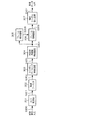
図4は、本第3の実施形態による、図3のフレーム・シンボルタイミング検出回路503の構成を示すブロック図である。図において、トレーニングシンボル部サンプル抽出回路601は、受信フィルタ302から出力された、オーバーサンプリングされた受信バースト信号S302から、トレーニングシンボル区間に相当するサンプル系列S601を入力サンプル毎に出力する。Nsサンプル(1シンボル時間)遅延回路602は、サンプル系列S601から、1シンボル時間に相当するサンプル遅延後の受信トレーニングシンボル部のサンプル系列S602を出力する。
FIG. 4 is a block diagram showing a configuration of the frame / symbol
複素共役乗算回路603は、1シンボル時間遅延前の受信トレーニングシンボル部のサンプル系列S601および1シンボル時間遅延後の受信トレーニングシンボル部のサンプル系列S602の複素共役乗算を行うことにより差動復号化を行う。1/Nsダウンサンプリング回路604は、1シンボル時間差動復号化後の受信トレーニングシンボル部のサンプル系列S603から、入力サンプル毎に1シンボル差動復号化後の受信トレーニングシンボル部のサンプル系列S604を出力する。
The complex
トレーニングシンボル生成回路605は、既知のトレーニングシンボル系列S605を生成する。1シンボル差動復号化回路606は、既知のトレーニングシンボル系列S605を、1シンボル差動復号化し、トレーニングシンボル系列S606を出力する。相互相関計算回路607は、1シンボル差動復号化後の受信トレーニングシンボル系列S604および1シンボル差動復号化後の既知のトレーニングシンボル系列S606の相互相関値S607を多値複素演算によって計算する。
The training
相関ピーク検出回路608は、受信バースト信号の入力サンプル毎に出力される相互相関値S607が最大となるサンプル位置を、フレーム・シンボル位置として検出し、フレーム・シンボルタイミング位置情報S503−1として出力するとともに、フレーム・シンボルタイミング位置S503−1に対応する相関ピーク値の位相成分を用いて搬送波周波数オフセットを推定し、搬送波周波数情報S503−2として出力する。これは、フレーム・シンボルタイミング検出処理において、トレーニングシンボル部における差動復号化処理が同期符号系列の自己相関演算に相当し、結果としてフレーム・シンボルタイミング検出位置における相互相関演算結果の位相成分に搬送波周波数オフセット成分が含まれることを利用している。
Correlation
上述した構成において、受信フィルタ302から出力されたオーバーサンプリングされた受信バースト信号S302は、トレーニングシンボル部サンプル抽出回路601に入力され、トレーニングシンボル区間に相当するサンプル系列S601が入力サンプル毎に出力される。受信トレーニングシンボル部サンプル系列S601は、Nsサンプル遅延回路602に入力され、1シンボル時間に相当するサンプル遅延後の受信トレーニングシンボル部サンプル系列S602が出力される。
In the configuration described above, the oversampled reception burst signal S302 output from the
1シンボル時間遅延前の受信トレーニングシンボル部サンプル系列S601および1シンボル時間遅延後の受信トレーニングシンボル部サンプル系列S602は、複素共役乗算回路603に入力されることによって差動復号化される。差動復号化後の受信トレーニングシンボル部サンプル系列S603は、ダウンサンプリング回路604に入力され、入力サンプル毎に1シンボル差動復号化後の受信トレーニングシンボル系列S604が出力される。
The received training symbol part
一方、トレーニングシンボル生成回路605では、無線送信装置で生成されるのと同じ既知のトレーニングシンボル系列S605が生成される。既知のトレーニングシンボル系列S605は、1シンボル差動復号化回路606に入力され、1シンボル差動復号化後の既知のトレーニングシンボル系列S606が出力される。1シンボル差動復号化後の受信トレーニングシンボル系列S604および1シンボル差動復号化後の既知のトレーニングシンボル系列S606は、相互相関計算回路607に入力され、両者の相互相関値S607が多値複素演算によって計算される。
On the other hand, the training
受信バースト信号の入力サンプル毎に出力される相互相関値S607は、相関ピーク検出回路608に入力され、相関値が最大となるサンプル位置がフレーム・シンボル位置として検出され、フレーム・シンボルタイミング位置情報S503−1として出力されるとともに、フレーム・シンボルタイミング位置S503−1に対応する相関ピーク値の位相成分を用いて搬送波周波数オフセットが推定され、搬送波周波数情報S503−2が併せて出力される。
The cross-correlation value S607 output for each input sample of the received burst signal is input to the correlation
上述した本第3の実施形態によれば、オーバーサンプリングされた受信バースト信号に対してスライディング相互相関演算を行うことにより、フレーム位置およびシンボルタイミング位置を共通のピーク位置として同時に検出することができる。 According to the third embodiment described above, the frame position and the symbol timing position can be simultaneously detected as a common peak position by performing a sliding cross-correlation operation on the oversampled received burst signal.
また、本第3の実施形態によれば、トレーニングシンボルの隣接シンボルに相当するサンプル間隔で複素共役演算を行う(差動復号化する)ことによって、受信信号から差動符号化前の同期符号系列を抽出することができる。また、検出された差動復号化後の同期符号系列と、既知のトレーニングシンボルの同期符号系列とのスライディング相互相関演算を行うことにより、そのフレーム位置およびシンボルタイミング位置を共通の位置として同時に検出することができる。 In addition, according to the third embodiment, a complex code operation (differential decoding) is performed at a sample interval corresponding to an adjacent symbol of a training symbol, so that a synchronization code sequence before differential encoding is performed from the received signal. Can be extracted. In addition, by performing a sliding cross-correlation operation between the detected synchronization code sequence after differential decoding and the synchronization code sequence of a known training symbol, the frame position and symbol timing position are simultaneously detected as a common position. be able to.
また、本第3の実施形態によれば、同期用トレーニングシンボル系列の差動復号化(遅延検波)を行うことによって、搬送波周波数同期前の搬送波周波数オフセットを相殺することができるため、送受信装置間の局所発振器誤差の影響による相互相関ピーク検出精度の劣化を低減することができる。 In addition, according to the third embodiment, the carrier frequency offset before the carrier frequency synchronization can be canceled by performing differential decoding (delay detection) of the synchronization training symbol sequence. It is possible to reduce the deterioration of the cross-correlation peak detection accuracy due to the influence of the local oscillator error.
なお、本第3の実施形態では、図4に示すフレーム・シンボルタイミング検出回路503では、トレーニングシンボル生成回路605として、図1に示したトレーニングシンボル生成回路102と同一構成を用いている。トレーニングシンボル生成回路605では、原同期符号系列の差動符号化が行われ、差動復号化回路606では、差動復号化が行われるが、いずれも既知の同期符号系列に対する信号処理であるため、実際には差動符号化および符号化の処理対を省略することもできる。
In the third embodiment, the frame / symbol
また、本第3の実施形態において、フレーム・シンボルタイミング検出回路503は、逐次トレーニングシンボル系列を生成できるトレーニングシンボル生成回路602を備えずに、代わりにトレーニングシンボル系列を記憶する記憶手段を備えるようにしてもよい。
In the third embodiment, the frame / symbol
D.第4の実施形態
次に、本発明の第4の実施形態について説明する。
本第4の実施形態は、上述した第3の実施形態と同様に、第2の実施形態の無線受信装置においてフレーム同期およびシンボルタイミング同期を実現するもので、オーバーサンプリングされた受信バースト信号から、トレーニングシンボル系列成分を抽出し、スライディング相互相関演算を行ってピーク位置を検出し、フレーム位置およびシンボルタイミング位置として同定することを特徴とする。第3の従来方式とは、サンプル毎に信号処理する点で異なる。
D. Fourth Embodiment Next, a fourth embodiment of the present invention will be described.
As in the third embodiment described above, the fourth embodiment realizes frame synchronization and symbol timing synchronization in the wireless reception device of the second embodiment. From the oversampled received burst signal, A training symbol sequence component is extracted, a sliding cross-correlation operation is performed, a peak position is detected, and it is identified as a frame position and a symbol timing position. This differs from the third conventional method in that signal processing is performed for each sample.
図5は、本第4の実施形態による、図3に示すフレーム・シンボルタイミング検出回路503の他の構成例を示すブロック図である。図において、トレーニングシンボル部サンプル抽出回路701は、受信フィルタ302から出力されたオーバーサンプリングされた受信バースト信号S302を、トレーニングシンボル区間に相当するサンプル系列S701として入力サンプル毎に出力する。1×Nsサンプル遅延回路702−1〜K×Nsサンプル遅延回路702−Kは、受信トレーニングシンボル部サンプル系列S701から、1〜Kシンボル時間に相当するサンプル遅延後の受信トレーニングシンボル部サンプル系列S702−1〜Kを出力する。
FIG. 5 is a block diagram showing another configuration example of the frame / symbol
複素共役乗算回路703−1〜703−Kは、時間遅延処理前の受信トレーニングシンボル部サンプル系列S701および1〜Kシンボル時間遅延後の受信トレーニングシンボル部サンプル系列S702−1〜S702−Kを差動復号化する。1/Nsダウンサンプリング回路704−1〜704−Kは、1〜Kシンボル時間差動復号化後の受信トレーニングシンボル部サンプル系列S703−1〜S703−Kから、入力サンプル毎に1〜Kシンボル差動復号化後の受信トレーニングシンボル系列S704−1〜S704−Kを出力する。 Complex conjugate multiplication circuits 703-1 to 703-K differentially receive received training symbol part sample series S701 before time delay processing and received training symbol part sample series S702-1 to S702-K after time delay of 1 to K symbols. Decrypt. The 1 / Ns downsampling circuits 704-1 to 704-K differ from the received training symbol part sample series S703-1 to S703-K after 1-K symbol time differential decoding by 1-K symbol differences for each input sample. Received training symbol sequences S704-1 to S704-K after the dynamic decoding are output.
トレーニングシンボル生成回路705は、既知のトレーニングシンボル系列S705を生成する。1〜Kシンボル差動復号化回路706−1〜706−Kは、既知のトレーニングシンボル系列S705から、1〜Kシンボル差動復号化後の既知のトレーニングシンボル系列S706−1〜S706−Kを出力する。相互相関計算回路707−1〜707−Kは、1〜Kシンボル差動復号化後の受信トレーニングシンボル系列S704−1〜S704−Kおよび1〜Kシンボル差動復号化後の既知のトレーニングシンボル系列S706−1〜S706−Kから、両者の相互相関値S707−1〜S707−Kを多値複素演算によって計算する。
The training
位相補償回路708は、相互相関値S707−1〜S707−Kから、差動符号化時の遅延時間差によって異なる搬送波周波数オフセットの影響の違いを補償し、位相補償後の相互相関値S708−1〜S708−Kとして出力する。和算回路709は、位相補償後の相互相関値S708−1〜S708−Kを和算し、相互相関値S709として出力する。相関ピーク検出回路710は、和算後の相互相関値S709から、受信バースト信号の入力サンプル毎に、相関値が最大となるサンプル位置がフレーム・シンボル位置として検出し、フレーム・シンボルタイミング位置情報S503−1として出力する。搬送波周波数推定回路711は、フレーム・シンボルタイミング位置S503−1に対応する相互相関値S707−1〜Kの位相成分を用いて搬送波周波数オフセットを推定し、搬送波周波数情報S503−2として出力する。これは、上述した第3の実施形態と同様に、フレーム・シンボルタイミング検出処理において、トレーニングシンボル部における差動復号化処理が同期符号系列の自己相関演算に相当し、結果としてフレーム・シンボルタイミング検出位置における相互相関演算結果の位相成分に搬送波周波数オフセット成分が含まれることを利用している。
The
上述した構成において、受信フィルタ302から出力されたオーバーサンプリングされた受信バースト信号S302は、トレーニングシンボル部サンプル抽出回路701に入力され、トレーニングシンボル区間に相当するサンプル系列S701が入力サンプル毎に出力される。受信トレーニングシンボル部サンプル系列S701は、1×Nsサンプル遅延回路702−1〜K×Nsサンプル遅延回路702−Kに入力され、1〜Kシンボル時間に相当するサンプル遅延後の受信トレーニングシンボル部サンプル系列S702−1〜S702−Kが出力される。時間遅延処理前の受信トレーニングシンボル部サンプル系列S701および1〜Kシンボル時間遅延後の受信トレーニングシンボル部サンプル系列S702−1〜S702−Kは、複素共役乗算回路703−1〜703−Kに入力されることによって差動復号化される。1〜Kシンボル時間差動復号化後の受信トレーニングシンボル部サンプル系列S703−1〜S703−Kは、ダウンサンプリング回路704−1〜704−1Kに入力され、入力サンプル毎に1〜Kシンボル差動復号化後の受信トレーニングシンボル系列S704−1〜S704−Kが出力される。
In the configuration described above, the oversampled reception burst signal S302 output from the
一方、トレーニングシンボル生成回路705では、既知のトレーニングシンボル系列S705が生成される。既知のトレーニングシンボル系列S705は、1〜Kシンボル差動復号化手段706−1〜706−Kに入力され、1〜Kシンボル差動復号化後の既知のトレーニングシンボル系列S706−1〜S706−Kが出力される。1〜Kシンボル差動復号化後の受信トレーニングシンボル系列S704−1〜S704−Kおよび1〜Kシンボル差動復号化後の既知のトレーニングシンボル系列S706−1〜S706−Kは、相互相関計算回路707−1〜Kに入力され、両者の相互相関値S707−1〜S707−Kが多値複素演算によって計算される。
On the other hand, the training
相互相関値S707−1〜S707−Kは、位相補償回路708に入力され、差動符号化時の遅延時間差によって異なる搬送波周波数オフセットの影響の違いが補償され、位相補償後の相互相関値S708−1〜S708−Kが出力される。位相補償後の相互相関値S708−1〜S708−Kは、和算回路709に入力され、和算後の相互相関値S709が出力される。和算後の相互相関値S709は、受信バースト信号の入力サンプル毎に相関ピーク検出回路710に入力され、相関値が最大となるサンプル位置がフレーム・シンボル位置として検出され、フレーム・シンボルタイミング位置情報S503−1として出力される。さらに、搬送波周波数推定回路711において、フレーム・シンボルタイミング位置S503−1に対応する相互相関値S707−1〜S707−Kの位相成分を用いて搬送波周波数オフセットを推定し、搬送波周波数情報S503−2として出力することもできる。
The cross-correlation values S707-1 to S707-K are input to the
上述した本第4の実施形態によれば、オーバーサンプリングされた受信バースト信号に対してスライディング相互相関演算を行うことにより、フレーム位置およびシンボルタイミング位置を共通のピーク位置として同時に検出することが可能である。 According to the fourth embodiment described above, it is possible to simultaneously detect the frame position and the symbol timing position as a common peak position by performing a sliding cross-correlation operation on the oversampled received burst signal. is there.
また、本第4の実施形態によれば、同期用トレーニングシンボル系列の差動復号化(遅延検波)を行うことによって、搬送波周波数同期前の搬送波周波数オフセットを相殺することができるため、送受信装置間の局所発振器誤差の影響による相互相関ピーク検出精度の劣化を低減することができる。 Also, according to the fourth embodiment, the carrier frequency offset before the carrier frequency synchronization can be canceled by performing differential decoding (delay detection) of the synchronization training symbol sequence. It is possible to reduce the deterioration of the cross-correlation peak detection accuracy due to the influence of the local oscillator error.
また、本第4の実施形態によれば、トレーニングシンボルの隣接シンボルに相当するサンプル間隔で複素共役演算を行う(差動復号化する)だけでなく、複数シンボルに相当するサンプル間隔でも複素共役演算(差動復号化する)ことによって、トレーニングシンボル系列長を長くするのと等価な効果を得ることができる。すなわち、同じトレーニングシンボル長でもフレーム同期およびシンボルタイミング同期精度が向上することから、伝送効率を劣化させずに対雑音同期特性を向上させることが可能となる。あるいは、対雑音同期特性を維持したまま、トレーニングシンボル長の短縮が可能となり、伝送効率を向上させることができる。 Further, according to the fourth embodiment, not only complex conjugate calculation (differential decoding) is performed at a sample interval corresponding to an adjacent symbol of the training symbol, but also complex conjugate calculation is performed at a sample interval corresponding to a plurality of symbols. By performing (differential decoding), an effect equivalent to increasing the training symbol sequence length can be obtained. That is, frame synchronization and symbol timing synchronization accuracy are improved even with the same training symbol length, so that it is possible to improve anti-noise synchronization characteristics without deteriorating transmission efficiency. Alternatively, the training symbol length can be shortened while maintaining anti-noise synchronization characteristics, and transmission efficiency can be improved.
また、本第4の実施形態によれば、トレーニングシンボル部における差動復号化処理は、同期符号系列の自己相関演算に相当する。したがって、nシンボルの差動復号化を前段で行う相互相関計算回路から出力される相互相関値の位相成分は、nシンボルあたりの送受信装置間の搬送波周波数オフセットを含んでおり、各相互相関計算回路から出力される各相互相関値の位相が揃わない。そこで、位相補償回路において各相互相関値の位相を揃えた後に和算処理を行うことで、搬送波周波数オフセットによる相関ピークの劣化を低減することができる。 Further, according to the fourth embodiment, the differential decoding process in the training symbol part corresponds to the autocorrelation calculation of the synchronization code sequence. Therefore, the phase component of the cross-correlation value output from the cross-correlation calculation circuit that performs differential decoding of n symbols in the previous stage includes the carrier frequency offset between the transmitting and receiving apparatuses per n symbols, and each cross-correlation calculation circuit The phases of the cross-correlation values output from are not aligned. Therefore, by performing summation processing after aligning the phases of the cross-correlation values in the phase compensation circuit, it is possible to reduce the degradation of the correlation peak due to the carrier frequency offset.
また、本第4の実施形態によれば、位相補償回路は、例えば、nシンボル差動復号化で得られた各相互相関値に対しては、その位相成分θnを検出した後、−{(n−1)/n}×θnの位相回転を与えることで実施できる。位相回転を施すことによって各相互相関値の位相成分を1/n、すなわち1シンボルあたりの位相回転量に揃えることができる。 Further, according to the fourth embodiment, for example, for each cross-correlation value obtained by n-symbol differential decoding, the phase compensation circuit detects the phase component θn, and then − {( It can be implemented by giving a phase rotation of (n-1) / n} × θn. By applying phase rotation, the phase component of each cross-correlation value can be adjusted to 1 / n, that is, the phase rotation amount per symbol.
なお、本第4の実施形態において、トレーニングシンボル系列長をNTRとすると、相互相関計算を行う前段の差動復号化の最大遅延時間K[シンボル]の上限値はNTR−1で与えられる。但し、位相補償回路のθnが±πを超えると、補償可能な引き込み位相範囲を超えて相関ピーク特性が劣化するため、θnが±πを超えない最大のnがKの上限値となる。実際に受信装置に実装するKの値は、さらに受信装置の回路規模、処理遅延、フレームおよびシンボルタイミング同期精度とのトレードオフなどで決定される。 In the fourth embodiment, assuming that the training symbol sequence length is NTR , the upper limit value of the maximum delay time K [symbol] of differential decoding in the previous stage for performing cross-correlation calculation is given by NTR- 1. . However, if θn of the phase compensation circuit exceeds ± π, the correlation peak characteristic deteriorates beyond the compensable pull-in phase range, so the maximum n where θn does not exceed ± π is the upper limit of K. The value of K that is actually mounted on the receiving apparatus is further determined by the trade-off between the circuit scale of the receiving apparatus, processing delay, frame and symbol timing synchronization accuracy, and the like.
E.第3の実施形態および第4の実施形態の実施例
次に、上述した第3の実施形態、および第4の実施形態の実施例について説明する。但し、上述した第3の実施形態は、第4の実施形態においてK=1とした場合と同じである。なお、トレーニングシンボル系列長を変化させた、第1の実施例及び第2の実施例についてフレーム誤検出率を評価している。
E. Examples of the third embodiment and the fourth embodiment Next, examples of the third embodiment and the fourth embodiment described above will be described. However, the third embodiment described above is the same as the case where K = 1 in the fourth embodiment. The frame error detection rate is evaluated for the first and second embodiments in which the training symbol sequence length is changed.
図6は、本第1の実施例、及び第2の実施例の計算機シミュレーション条件を示す表図である。トレーニングシンボルの変調方式としてBPSK、情報シンボルの変調方式としてBPSKあるいはQPSKを仮定した。また、低CNR領域において良好な無線伝送特性を得るために、畳み込み符号化およびビタビ復号化を用いた誤り訂正を仮定した。伝搬路モデルとしては、白色ガウス雑音環境(Additive White Gaussian Noise:AWGN)を仮定した。 FIG. 6 is a table showing computer simulation conditions of the first and second embodiments. BPSK is assumed as the training symbol modulation method, and BPSK or QPSK is assumed as the information symbol modulation method. Also, in order to obtain good radio transmission characteristics in the low CNR region, error correction using convolutional coding and Viterbi decoding was assumed. As a propagation path model, an additive white Gaussian noise (AWGN) was assumed.
図7(a)、(b)は、本第1の実施例、及び第2の実施例で用いたバースト構成を示す概念図である。第1の実施例においては、32シンボルの情報シンボル系列の前後に8シンボルずつ、第1の実施例においては、同じく16シンボルずつのトレーニングシンボル系列を付加した。なお、同期符号系列としては、それぞれ符号長7および符号長15のM系列を使用し、これを差動符号化したものをトレーニングシンボル系列とした。 FIGS. 7A and 7B are conceptual diagrams showing burst configurations used in the first and second embodiments. In the first embodiment, training symbol sequences of 8 symbols are added before and after the information symbol sequence of 32 symbols, and in the first embodiment, 16 symbol symbols are added similarly. Note that, as a synchronization code sequence, an M sequence having a code length of 7 and a code length of 15 was used, respectively, and a differentially encoded sequence was used as a training symbol sequence.
図8は、本第1の実施例及び第2の実施例において、フレーム誤検出率=1%を満足する所要CNR特性を示す図である。図6に示したパラメータ条件で同期検波を用いた場合、情報シンボルパケット誤り率=1%を満たす所要CNR特性が、QPSKにおいて約3dB、BPSKにおいて約0dBである。上述した第3の実施形態を用いたK=1の場合には、第1の実施例および第2の実施例にそれぞれQPSKとBPSKを適用した場合には、フレーム誤検出率とパケット誤り率とが同水準の所要CNR特性となり、無線バースト通信システムの設計としては、トレーニングシンボル長がやや不足している。ここで、上述した第4の実施形態を適用してK≧2とすることによって、所要CNRの余裕を1dB以上確保することが可能となり、トレーニングシンボル長を大きくすることなく、フレーム誤検出率をパケット誤り率よりも十分小さくすることが可能となる。 FIG. 8 is a diagram showing required CNR characteristics satisfying the frame misdetection rate = 1% in the first and second embodiments. When synchronous detection is used under the parameter conditions shown in FIG. 6, the required CNR characteristic that satisfies the information symbol packet error rate = 1% is about 3 dB in QPSK and about 0 dB in BPSK. In the case of K = 1 using the third embodiment described above, when QPSK and BPSK are applied to the first and second examples, respectively, the frame error detection rate and the packet error rate are Therefore, the required CNR characteristics of the same level are obtained, and the training symbol length is slightly insufficient as a design of the radio burst communication system. Here, by applying the above-described fourth embodiment and setting K ≧ 2, it is possible to secure a required CNR margin of 1 dB or more, and to increase the frame error detection rate without increasing the training symbol length. It becomes possible to make it sufficiently smaller than the packet error rate.
また、第1の実施例と第2の実施例とを比較すると、Kの値が同じ場合、トレーニングシンボル長の違いが、フレーム同期特性にして約2.5dB程度の違いであることが分かる。ここで、第1の実施例のK=3と、第2の実施例のK=1とがほぼ同じ同期特性であることからも、第4の実施形態では、フレーム同期特性を劣化させることなく伝送効率を向上させることが分かる。 Further, comparing the first and second embodiments, it can be seen that when the value of K is the same, the difference in training symbol length is about 2.5 dB in terms of frame synchronization characteristics. Here, since K = 3 in the first embodiment and K = 1 in the second embodiment have substantially the same synchronization characteristics, the fourth embodiment does not deteriorate the frame synchronization characteristics. It can be seen that the transmission efficiency is improved.
上述した第1〜第4の実施形態によれば、無線バースト通信においてオーバーヘッドによる伝送効率劣化を低減することができる。また、無線受信装置における信号処理演算量を低減しつつ、フレームおよびシンボルタイミング同期を確立することができる。また、低速無線通信においても、高精度な同期特性を実現するフレームおよびシンボルタイミング同期を確立することができる。また、より短いトレーニングシンボル長で、雑音耐性の高いフレームおよびシンボルタイミング同期を確立することができる。また、フレームおよびシンボルタイミング同期を確立するのと同時に搬送波周波数同期も確立することができる。 According to the first to fourth embodiments described above, it is possible to reduce transmission efficiency deterioration due to overhead in wireless burst communication. In addition, frame and symbol timing synchronization can be established while reducing the amount of signal processing computation in the wireless reception device. Also in low-speed wireless communication, frame and symbol timing synchronization that achieves highly accurate synchronization characteristics can be established. Also, frame and symbol timing synchronization with high noise tolerance can be established with a shorter training symbol length. Also, carrier frequency synchronization can be established at the same time as frame and symbol timing synchronization is established.
101 シンボル生成回路
102 トレーニングシンボル生成回路
103 多重化回路
104 送信フィルタ
105 D/A変換回路
201 同期符号系列生成回路
202 差動符号化回路
301 A/D変換器
302 受信フィルタ
503 フレーム・シンボルタイミング検出回路
504 フレーム・シンボルタイミング同期回路
505 情報シンボル識別回路
601 トレーニングシンボル部サンプル抽出回路
602 Nsサンプル遅延回路
603 複素共役乗算回路
604 1/Nsダウンサンプリング回路
605 トレーニングシンボル生成回路
606 1シンボル差動復号化回路
607 相互相関計算回路
608 相関ピーク検出回路
701 トレーニングシンボル部サンプル抽出回路
702−1〜702−K 1〜K×Nsサンプル遅延回路
703−1〜703−K 複素共役乗算回路
704−1〜704−K 1/Nsダウンサンプリング回路
705 トレーニングシンボル生成回路
706−1〜706−K 1〜Kシンボル差動復号化回路
707−1〜707−K 相互相関計算回路
708 位相補償回路
709 和算回路
710 相関ピーク検出回路
711 搬送波周波数推定回路
Claims (8)
前記無線バースト信号に含まれるトレーニングシンボル系列を用いて、オーバーサンプリングされた受信バースト信号系列からフレーム・シンボルタイミングを検出するフレーム・シンボルタイミング検出手段と、
前記フレーム・シンボルタイミング検出手段で検出されたフレーム・シンボルタイミングに基づいて、受信バーストシンボル系列を抽出するフレーム・シンボルタイミング同期手段と、
前記フレーム・シンボルタイミング同期手段で抽出された受信バーストシンボル系列から受信情報シンボル系列を抽出してシンボル識別を行うシンボル識別手段と
を備え、
前記フレーム・シンボルタイミング検出手段は、
前記トレーニングシンボル区間に相当する受信信号サンプルを入力サンプル毎に出力するトレーニングシンボル部サンプル抽出手段と、
前記トレーニングシンボル部サンプル抽出手段から出力された受信トレーニングシンボル部信号サンプルを1〜n(nは1以上の整数)シンボル時間相当のサンプル時間遅延させて出力するn個の遅延手段と、
前記トレーニングシンボル部サンプル抽出手段から出力された受信トレーニングシンボル部信号サンプル系列と、前記n個の遅延手段から出力された受信トレーニングシンボル部信号サンプル系列との複素共役乗算を行い、受信トレーニングシンボル部サンプル系列のそれぞれ1〜nシンボル時間差動復号化を行うn個の複素共役乗算手段と、
前記n個の複素共役乗算手段から出力されたトレーニングシンボル部信号サンプルのダウンサンプリングを行い、差動復号化された受信トレーニングシンボル系列を抽出するn個のダウンサンプリング手段と、
既知のトレーニングシンボル系列を生成するトレーニングシンボル生成手段と、
前記トレーニングシンボル生成手段から出力されるトレーニングシンボル系列の1〜nシンボル時間差動復号化を行うn個の差動復号化手段と、
前記差動復号化された受信トレーニングシンボル系列と、前記差動復号化された既知のトレーニングシンボル系列との相互相関値を計算し、入力サンプル毎に出力するn個の相互相関値計算手段と、
前記n個の相互相関値計算手段から出力されたn個の相互相関値に基づいて、前記相互相関値が最大となるサンプル位置をフレーム・シンボルタイミング位置として検出する相関ピーク検出手段と
を備えることを特徴とする無線受信装置。 In a radio receiver that receives a radio burst signal composed of a training symbol and an information symbol, using a differentially encoded synchronous code sequence as a training symbol,
Frame symbol timing detection means for detecting frame symbol timing from an oversampled received burst signal sequence using a training symbol sequence included in the radio burst signal;
Frame symbol timing synchronization means for extracting a received burst symbol sequence based on the frame symbol timing detected by the frame symbol timing detection means;
Symbol identifying means for extracting a received information symbol sequence from the received burst symbol sequence extracted by the frame / symbol timing synchronizing means and performing symbol identification;
The frame symbol timing detection means includes:
Training symbol part sample extracting means for outputting a received signal sample corresponding to the training symbol section for each input sample;
N delay means for outputting the received training symbol part signal samples output from the training symbol part sample extracting means with a sample time delay equivalent to 1 to n (n is an integer of 1 or more) symbol time;
A received training symbol part sample is obtained by performing complex conjugate multiplication of the received training symbol part signal sample series output from the training symbol part sample extracting means and the received training symbol part signal sample series output from the n delay means. N complex conjugate multiplier means for performing 1-n symbol time differential decoding of each of the sequences;
N down-sampling means for down-sampling the training symbol portion signal samples output from the n complex conjugate multiplication means and extracting a differentially decoded received training symbol sequence;
Training symbol generation means for generating a known training symbol sequence;
N differential decoding means for performing 1 to n symbol time differential decoding of the training symbol series output from the training symbol generating means;
N cross-correlation value calculating means for calculating a cross-correlation value between the differentially decoded received training symbol sequence and the differentially-decoded known training symbol sequence, and outputting each input sample;
Correlation peak detection means for detecting, as a frame symbol timing position, a sample position at which the cross correlation value is maximum based on n cross correlation values output from the n cross correlation value calculation means. A wireless receiver characterized by the above.
前記n個の相互相関値計算手段から出力されたn個の相互相関値に対し、各シンボル遅延時間に対応して位相補償を行う位相補償手段と、
前記位相補償手段から出力されたn個の位相補償後相互相関値の和を計算する和算手段と、をさらに備え、
前記相関ピーク検出手段は、前記和算手段から前記相互相関値が最大となるサンプル位置をフレーム・シンボルタイミング位置として検出することを特徴とする請求項1記載の無線受信装置。 The frame symbol timing detection means includes :
Over the previous SL n number of cross-correlation values of n of the cross-correlation values output from the calculation means, and phase compensating means for performing phase compensation corresponding to each symbol delay time,
A summing means for calculating a sum of n phase-compensated cross-correlation values output from the phase compensation means ;
The correlation peak detection means, radio receiving apparatus according to claim 1, wherein the cross-correlation value from said summing means and wherein the benzalkonium detecting the sample position with the maximum as the frame symbol timing position.
さらに搬送波周波数の推定を行い、
前記フレーム・シンボルタイミング同期手段は、
さらに搬送波周波数同期を行い、
前記相関ピーク検出手段は、
さらに前記フレーム・シンボルタイミング位置の相互相関値の位相成分から搬送波周波数を推定し、
前記フレーム・シンボルタイミング同期手段は、
さらに搬送波周波数同期を行うことを特徴とする請求項1記載の無線受信装置。 The frame symbol timing detection means includes:
In addition, the carrier frequency is estimated,
The frame symbol timing synchronization means includes:
In addition, carrier frequency synchronization
The correlation peak detecting means includes
Further, the carrier frequency is estimated from the phase component of the cross-correlation value of the frame symbol timing position,
The frame symbol timing synchronization means includes:
Radio receiving apparatus according to claim 1 further characterized by performing the carrier frequency synchronization.
さらに搬送波周波数の推定を行い、
前記フレーム・シンボルタイミング同期手段は、
さらに搬送波周波数同期を行い、
前記相関ピーク検出手段は、
さらに前記フレーム・シンボルタイミング位置の和算前の相互相関値の一部あるいは全てを用いて、その位相成分から搬送波周波数を推定し、
前記フレーム・シンボルタイミング同期手段は、
フレーム・シンボルタイミングだけでなく搬送波周波数同期を行うことを特徴とする請求項2記載の無線受信装置。 The frame symbol timing detection means includes:
In addition, the carrier frequency is estimated,
The frame symbol timing synchronization means includes:
In addition, carrier frequency synchronization
The correlation peak detecting means includes
Further, by using a part or all of the cross-correlation value before summation of the frame symbol timing position, the carrier frequency is estimated from the phase component,
The frame symbol timing synchronization means includes:
3. The radio receiving apparatus according to claim 2 , wherein not only frame symbol timing but also carrier frequency synchronization is performed.
前記無線バースト信号に含まれる既知のトレーニングシンボル系列を用いて、オーバーサンプリングされた受信バースト信号系列からフレーム・シンボルタイミングを検出するフレーム・シンボルタイミング検出ステップと、
前記フレーム・シンボルタイミング検出ステップで検出されたフレーム・シンボルタイミングに基づいて、受信バーストシンボル系列を抽出するフレーム・シンボルタイミング同期ステップと、
前記フレーム・シンボルタイミング同期ステップで抽出された受信バーストシンボル系列から受信情報シンボル系列を抽出してシンボル識別を行うシンボル識別ステップと
を含み、
前記フレーム・シンボルタイミング検出ステップにおいては、
前記トレーニングシンボル区間に相当する受信信号サンプルを入力サンプル毎に出力するトレーニングシンボル部サンプル抽出ステップと、
前記トレーニングシンボル部サンプル抽出ステップにおいて出力された受信トレーニングシンボル部信号サンプルを1〜n(nは1以上の整数)シンボル時間相当のサンプル時間遅延させて出力するn回の遅延ステップと、
前記トレーニングシンボル部サンプル抽出ステップにおいて出力された受信トレーニングシンボル部信号サンプル系列と、前記n回の遅延ステップにおいて出力された受信トレーニングシンボル部信号サンプル系列との複素共役乗算を行い、受信トレーニングシンボル部サンプル系列のそれぞれ1〜nシンボル時間差動復号化を行うn回の複素共役乗算ステップと、
前記n回の複素共役乗算ステップにおいて出力されたトレーニングシンボル部信号サンプルのダウンサンプリングを行い、差動復号化された受信トレーニングシンボル系列を抽出するn回のダウンサンプリングステップと、
既知のトレーニングシンボル系列を生成するトレーニングシンボル生成ステップと、
前記トレーニング抽出ステップにおいて出力されるトレーニングシンボル系列の1〜nシンボル時間差動復号化を行うn回の差動復号化ステップと、
前記差動復号化された受信トレーニングシンボル系列と、前記差動復号化された既知のトレーニングシンボル系列との相互相関値を計算し、入力サンプル毎に出力するn回の相互相関値計算ステップと、
前記n回の相互相関値計算ステップにおいて出力されたn個の相互相関値に基づいて、前記相互相関値が最大となるサンプル位置をフレーム・シンボルタイミング位置として検出する相関ピーク検出ステップとを含むことを特徴とする無線受信方法。 In a radio receiving method for receiving a radio burst signal composed of a training symbol and an information symbol, using a differentially encoded synchronous code sequence as a training symbol,
A frame symbol timing detection step for detecting a frame symbol timing from an oversampled received burst signal sequence using a known training symbol sequence included in the radio burst signal;
A frame symbol timing synchronization step for extracting a received burst symbol sequence based on the frame symbol timing detected in the frame symbol timing detection step;
A symbol identifying step of extracting a received information symbol sequence from the received burst symbol sequence extracted in the frame symbol timing synchronization step and performing symbol identification;
In the frame symbol timing detection step,
A training symbol portion sample extraction step for outputting a received signal sample corresponding to the training symbol section for each input sample;
N delay steps for outputting the received training symbol portion signal samples output in the training symbol portion sample extraction step with a sample time delay equivalent to 1 to n (n is an integer of 1 or more) symbol time;
A received training symbol part sample is obtained by performing complex conjugate multiplication of the received training symbol part signal sample sequence output in the training symbol part sample extraction step and the received training symbol part signal sample sequence output in the n delay steps. N complex conjugate multiplication steps for 1-n symbol time differential decoding of each of the sequences;
Down-sampling steps of down-sampling the training symbol part signal samples output in the n-time complex conjugate multiplication steps to extract a differentially decoded received training symbol sequence;
A training symbol generation step for generating a known training symbol sequence;
N differential decoding steps for performing 1-n symbol time differential decoding of the training symbol sequence output in the training extraction step;
N cross-correlation value calculating steps for calculating a cross-correlation value between the differentially decoded received training symbol sequence and the differentially-decoded known training symbol sequence, and outputting each input sample;
A correlation peak detection step of detecting, as a frame symbol timing position, a sample position where the cross-correlation value is maximum based on the n cross-correlation values output in the n-time cross-correlation value calculation step. A wireless reception method characterized by the above.
前記n回の相互相関値計算ステップにおいて出力されたn個の相互相関値に対し、各シンボル遅延時間に対応して位相補償を行う位相補償ステップと、
前記位相補償ステップにおいて出力されたn個の位相補償後相互相関値の和を計算する和算ステップと、をさらに含み、
前記相関ピーク検出ステップでは、前記和算ステップにおいて前記相互相関値が最大となるサンプル位置をフレーム・シンボルタイミング位置として検出することを特徴とする請求項5記載の無線受信方法。 In the frame symbol timing detection step ,
For n-number of cross-correlation values output before Symbol n times of the cross-correlation value calculation step, the phase compensation step of performing phase compensation corresponding to each symbol delay time,
A summation step of calculating a sum of the n phase-compensated cross-correlation values output in the phase compensation step ,
Wherein in the correlation peak detection step, the radio receiving method according to claim 5, wherein said cross-correlation value in said summing step and said and Turkey detecting the sample position with the maximum as the frame symbol timing position.
さらに搬送波周波数の推定を行い、
前記フレーム・シンボルタイミング同期ステップにおいては、
さらに搬送波周波数同期を行い、
前記相関ピーク検出手段ステップにおいては、
さらに前記フレーム・シンボルタイミング位置の相互相関値の位相成分から搬送波周波数を推定し、
前記フレーム・シンボルタイミング同期手段ステップにおいては、
さらに搬送波周波数同期を行うことを特徴とする請求項5記載の無線受信方法。 In the frame symbol timing detection step,
In addition, the carrier frequency is estimated,
In the frame symbol timing synchronization step,
In addition, carrier frequency synchronization
In the correlation peak detecting means step,
Further, the carrier frequency is estimated from the phase component of the cross-correlation value of the frame symbol timing position,
In the frame symbol timing synchronization means step,
6. The radio reception method according to claim 5, further comprising performing carrier frequency synchronization.
さらに搬送波周波数の推定を行い、
前記フレーム・シンボルタイミング同期ステップにおいては、
さらに搬送波周波数同期を行い、
前記相関ピーク検出手段ステップにおいては、
さらに前記フレーム・シンボルタイミング位置の和算前の相互相関値の一部あるいは全てを用いて、その位相成分から搬送波周波数を推定し、
前記フレーム・シンボルタイミング同期手段ステップにおいては、
フレーム・シンボルタイミングだけでなく搬送波周波数同期を行うことを特徴とする請求項6記載の無線受信方法。 In the frame symbol timing detection step,
In addition, the carrier frequency is estimated,
In the frame symbol timing synchronization step,
In addition, carrier frequency synchronization
In the correlation peak detecting means step,
Further, by using a part or all of the cross-correlation value before summation of the frame symbol timing position, the carrier frequency is estimated from the phase component,
In the frame symbol timing synchronization means step,
7. The radio reception method according to claim 6 , wherein not only frame symbol timing but also carrier frequency synchronization is performed.
Priority Applications (1)
| Application Number | Priority Date | Filing Date | Title |
|---|---|---|---|
| JP2008011826A JP5219528B2 (en) | 2008-01-22 | 2008-01-22 | Radio receiving apparatus and radio receiving method |
Applications Claiming Priority (1)
| Application Number | Priority Date | Filing Date | Title |
|---|---|---|---|
| JP2008011826A JP5219528B2 (en) | 2008-01-22 | 2008-01-22 | Radio receiving apparatus and radio receiving method |
Publications (2)
| Publication Number | Publication Date |
|---|---|
| JP2009177341A JP2009177341A (en) | 2009-08-06 |
| JP5219528B2 true JP5219528B2 (en) | 2013-06-26 |
Family
ID=41032008
Family Applications (1)
| Application Number | Title | Priority Date | Filing Date |
|---|---|---|---|
| JP2008011826A Expired - Fee Related JP5219528B2 (en) | 2008-01-22 | 2008-01-22 | Radio receiving apparatus and radio receiving method |
Country Status (1)
| Country | Link |
|---|---|
| JP (1) | JP5219528B2 (en) |
Families Citing this family (8)
| Publication number | Priority date | Publication date | Assignee | Title |
|---|---|---|---|---|
| US8644766B2 (en) | 2008-04-21 | 2014-02-04 | Nippon Telegraph And Telephone Corporation | Radio communication system, transmission device, reception device, radio communication method, transmission method, reception method |
| JP5962987B2 (en) * | 2012-09-28 | 2016-08-03 | パナソニックIpマネジメント株式会社 | Synchronization system, receiving device including the same, communication system including the same, and synchronization method |
| JP5962988B2 (en) * | 2012-09-28 | 2016-08-03 | パナソニックIpマネジメント株式会社 | Communication system, transmitter and receiver used therefor, and communication method |
| JP5942226B2 (en) * | 2012-11-13 | 2016-06-29 | パナソニックIpマネジメント株式会社 | Communication system, transmitter and receiver used therefor, and communication method |
| US9344270B2 (en) * | 2013-03-14 | 2016-05-17 | Qualcomm Incorporated | Phase detection and correction for non-continuous local oscillator generator |
| KR101523149B1 (en) * | 2013-12-31 | 2015-05-26 | 세종대학교산학협력단 | Timing offset estimation method for single carrier system and apparatus thereof |
| CN115776314B (en) * | 2023-02-13 | 2023-04-25 | 江苏芯云电子科技有限公司 | HPLC dual-mode wireless system synchronous detection method and device |
| CN117479288B (en) * | 2023-11-27 | 2024-09-03 | 中国人民解放军军事科学院系统工程研究院 | Timing synchronization method and device for burst signal test |
Family Cites Families (5)
| Publication number | Priority date | Publication date | Assignee | Title |
|---|---|---|---|---|
| JPS5980026A (en) * | 1982-10-30 | 1984-05-09 | Nec Corp | Training detecting circuit |
| JPH0795189A (en) * | 1993-09-24 | 1995-04-07 | Uniden Corp | Frame synchronization system for digital communication |
| JP3805135B2 (en) * | 1999-05-28 | 2006-08-02 | 三菱電機株式会社 | Synchronization establishment method, synchronization establishment apparatus, and communication system |
| CN101292486B (en) * | 2005-09-06 | 2012-10-10 | 日本电信电话株式会社 | Radio transmitting apparatus, radio receiving apparatus, radio transmitting method, radio receiving method, wireless communication system and wireless communication method |
| JP4527101B2 (en) * | 2006-11-20 | 2010-08-18 | 日本電信電話株式会社 | Burst radio signal transmission system, radio transmitter, radio receiver and burst radio signal transmission method |
-
2008
- 2008-01-22 JP JP2008011826A patent/JP5219528B2/en not_active Expired - Fee Related
Also Published As
| Publication number | Publication date |
|---|---|
| JP2009177341A (en) | 2009-08-06 |
Similar Documents
| Publication | Publication Date | Title |
|---|---|---|
| JP5219528B2 (en) | Radio receiving apparatus and radio receiving method | |
| Sure et al. | A survey on OFDM channel estimation techniques based on denoising strategies | |
| JP4913081B2 (en) | Wireless transmission device, wireless reception device, wireless communication system, wireless communication method, wireless transmission method, and wireless reception method | |
| US7466768B2 (en) | IQ imbalance compensation | |
| US7068593B2 (en) | Apparatus and method for synchronizing frequency in orthogonal frequency division multiplexing communication system | |
| CN102480452B (en) | Carrier frequency synchronization circuit and method of OFDM system | |
| CN101621491B (en) | Receiver and method for receiving digital signal | |
| JPWO2007029702A1 (en) | Wireless transmission device, wireless reception device, wireless transmission method, wireless reception method, and wireless communication system and wireless communication method | |
| CN104168227B (en) | Carrier synchronization method applied to orthogonal frequency division multiplexing system | |
| CN101438523A (en) | Radio transmitter, radio receiver, and pilot generating method | |
| KR101485785B1 (en) | Method and Apparatus for estimating carrier frequency in a wireless communication system | |
| CN104081840A (en) | Multi-stage timing and frequency synchronization | |
| CN101321150B (en) | Combined synchronization process and its receiving terminal based on two-dimension short time slippage self-correlation | |
| CN108566266B (en) | Reliable transmission method and device for broadband private network under high-speed mobile channel | |
| CN113315595A (en) | Downlink initial synchronization tracking method of narrow-band Internet of things system | |
| EP4322489A1 (en) | M-fsk modulation-based receiver and reception method therefor | |
| CN101018083A (en) | Dopla frequency shift compensation method in the MPSK mobile communication system | |
| KR20070049832A (en) | Method and apparatus for estimating frequency offset in mobile communications system | |
| CN102868660A (en) | Downlink transmission synchronization method based on broadband wireless communication system | |
| CN108900281B (en) | Method for estimating time delay outside symbol | |
| CN111555856B (en) | Guiding auxiliary synchronization method based on multipath differential weighted correlation | |
| CN108923886B (en) | Unique code type detection method | |
| WO2001052493A1 (en) | Method for blind modulation detection | |
| CN103428147B (en) | A kind of method that TDD-LTE system frequency deviation compensates | |
| CN104539564A (en) | Frequency offset estimation method and device for LTE (Long Term Evolution) system |
Legal Events
| Date | Code | Title | Description |
|---|---|---|---|
| A621 | Written request for application examination |
Free format text: JAPANESE INTERMEDIATE CODE: A621 Effective date: 20100127 |
|
| A977 | Report on retrieval |
Free format text: JAPANESE INTERMEDIATE CODE: A971007 Effective date: 20120224 |
|
| A131 | Notification of reasons for refusal |
Free format text: JAPANESE INTERMEDIATE CODE: A131 Effective date: 20120228 |
|
| A521 | Written amendment |
Free format text: JAPANESE INTERMEDIATE CODE: A523 Effective date: 20120427 |
|
| A131 | Notification of reasons for refusal |
Free format text: JAPANESE INTERMEDIATE CODE: A131 Effective date: 20121221 |
|
| A521 | Written amendment |
Free format text: JAPANESE INTERMEDIATE CODE: A523 Effective date: 20130206 |
|
| TRDD | Decision of grant or rejection written | ||
| A01 | Written decision to grant a patent or to grant a registration (utility model) |
Free format text: JAPANESE INTERMEDIATE CODE: A01 Effective date: 20130226 |
|
| A61 | First payment of annual fees (during grant procedure) |
Free format text: JAPANESE INTERMEDIATE CODE: A61 Effective date: 20130305 |
|
| FPAY | Renewal fee payment (event date is renewal date of database) |
Free format text: PAYMENT UNTIL: 20160315 Year of fee payment: 3 |
|
| R151 | Written notification of patent or utility model registration |
Ref document number: 5219528 Country of ref document: JP Free format text: JAPANESE INTERMEDIATE CODE: R151 |
|
| FPAY | Renewal fee payment (event date is renewal date of database) |
Free format text: PAYMENT UNTIL: 20160315 Year of fee payment: 3 |
|
| S531 | Written request for registration of change of domicile |
Free format text: JAPANESE INTERMEDIATE CODE: R313531 |
|
| R350 | Written notification of registration of transfer |
Free format text: JAPANESE INTERMEDIATE CODE: R350 |
|
| LAPS | Cancellation because of no payment of annual fees |