JP5218213B2 - Waterproof connector - Google Patents
Waterproof connector Download PDFInfo
- Publication number
- JP5218213B2 JP5218213B2 JP2009084879A JP2009084879A JP5218213B2 JP 5218213 B2 JP5218213 B2 JP 5218213B2 JP 2009084879 A JP2009084879 A JP 2009084879A JP 2009084879 A JP2009084879 A JP 2009084879A JP 5218213 B2 JP5218213 B2 JP 5218213B2
- Authority
- JP
- Japan
- Prior art keywords
- terminal
- fitting
- retainer
- locking position
- locking
- Prior art date
- Legal status (The legal status is an assumption and is not a legal conclusion. Google has not performed a legal analysis and makes no representation as to the accuracy of the status listed.)
- Expired - Fee Related
Links
Images
Landscapes
- Connector Housings Or Holding Contact Members (AREA)
Description
本発明は、防水コネクタに関する。 The present invention relates to a waterproof connector.
従来より、防水コネクタとして、端子金具が収容される端子収容部と、端子収容部の周りを囲って相手側コネクタとの嵌合方向に開口するフード部とを有し、そのハウジングに、端子収容部からの端子金具の抜け出しを規制するリテーナが組み付けられるものが知られている。 Conventionally, as a waterproof connector, it has a terminal accommodating portion that accommodates a terminal fitting, and a hood portion that surrounds the terminal accommodating portion and opens in a fitting direction with a mating connector, and the housing accommodates the terminal. It is known that a retainer that restricts the removal of the terminal fitting from the part is assembled.
例えば特許文献1に記載の防水コネクタには、フード部の側面に形成したリテーナ挿入孔から組み付けられて、端子金具の挿抜を許容する仮係止位置と、端子金具の挿抜を規制する本係止位置との間を移動可能とされたサイドタイプのリテーナが備えられている。また、例えば特許文献2に記載の防水コネクタには、ハウジングに対してフード部の開口から組み付けられて仮係止位置に保持され、フード部の奥方へ押されることにより本係止位置に移動するフロントタイプのリテーナが備えられている。
For example, the waterproof connector described in
ところで、上記のようなサイドタイプのリテーナを備えた防水コネクタは、フード部の側面にリテーナ挿入孔を形成しなければならないので、防水性を確保する点で不利である。
また、上記のようなフロントタイプのリテーナを備えた防水コネクタは、リテーナを仮係止位置から本係止位置に移動させる前に、誤って相手側コネクタと嵌合させようとしたときには、リテーナが仮係止位置に保持されたままであるにもかかわらず、相手側コネクタに押されてフード部の奥方に移動し、相手側コネクタが無理に嵌合してしまうことが懸念される。
By the way, the waterproof connector provided with the side type retainer as described above is disadvantageous in that waterproofness is ensured because a retainer insertion hole must be formed on the side surface of the hood portion.
In addition, the waterproof connector having the front type retainer as described above is not used when the retainer is accidentally engaged with the mating connector before the retainer is moved from the temporary locking position to the final locking position. In spite of being held in the temporary locking position, there is a concern that the mating connector is pushed by the mating connector and moves to the back of the hood portion, and the mating connector is forcibly fitted.
本発明は上記のような事情に基づいて完成されたものであって、防水性を確保する点で有利で、かつリテーナが仮係止位置に保持された状態での相手側コネクタとの嵌合を防止することが可能な防水コネクタを提供することを目的とする。 The present invention has been completed based on the above circumstances, and is advantageous in securing waterproofness, and is fitted with a mating connector in a state in which the retainer is held at the temporary locking position. An object of the present invention is to provide a waterproof connector capable of preventing the above.
本発明の防水コネクタは、端子金具を収容する端子収容部と、この端子収容部の周りを囲って相手側コネクタとの嵌合方向に開口するフード部とを有するとともに、前記端子収容部と前記フード部との間に前記相手側コネクタが嵌合する嵌合空間が形成されたハウジングと、前記ハウジングに対して前記フード部の開口から組み付けられて前記端子金具の挿抜を許容する仮係止位置に保持され、前記仮係止位置から前記相手側コネクタとの嵌合方向と交差する方向へ移動して前記端子金具の挿抜を規制する本係止位置に至り、前記仮係止位置にあるときには前記嵌合空間内に位置し、前記本係止位置にあるときには前記嵌合空間から退避するリテーナと、を備え、前記リテーナは、前記端子収容部の前記嵌合方向の前方に配されて前記端子金具の前止まりとなる前壁を有する前止め部と、前記仮係止位置にあるときには前記端子金具から離間して同端子金具の挿抜を許容し、前記本係止位置にあるときには前記端子金具に係止して同端子金具の挿抜を規制する係止部が設けられるとともに前記端子収容部の一面側に配された抜け止め部と、前記抜け止め部の前記嵌合方向の後方に設けられて前記端子収容部の外周面に設けられたシールリングの抜け止めを図る張出部と、前記抜け止め部の前記端子収容部をはさんで反対側に配されるとともに前記前壁の周縁から前記嵌合方向の後方に突出する周壁と、を有するものである。 The waterproof connector according to the present invention includes a terminal accommodating portion that accommodates the terminal fitting, and a hood portion that surrounds the terminal accommodating portion and opens in a fitting direction with the mating connector. A housing in which a mating space is formed between the mating connector and the hood portion, and a temporary locking position that is assembled to the housing from the opening of the hood portion and allows the terminal fitting to be inserted and removed. Is moved to a direction crossing the fitting direction with the mating connector from the temporary locking position to reach a final locking position for restricting insertion / extraction of the terminal fitting, and when in the temporary locking position A retainer that is located in the fitting space and retracts from the fitting space when in the main locking position, and the retainer is disposed in front of the terminal accommodating portion in the fitting direction, and Terminal gold And a front stopper portion having a front wall that is a front stop of the terminal member, and when being in the temporary locking position, the terminal metal member is allowed to be separated from the terminal metal member when being in the temporary locking position. A locking portion for locking and restricting insertion / extraction of the terminal fitting is provided, a retaining portion disposed on one side of the terminal accommodating portion, and provided behind the retaining portion in the fitting direction. A projecting portion for preventing the seal ring provided on the outer peripheral surface of the terminal accommodating portion from being disposed on the opposite side of the terminal accommodating portion of the retaining portion from the periphery of the front wall And a peripheral wall protruding rearward in the fitting direction .
このような構成によれば、リテーナは、フード部の開口から組み付けられるから、フード部の側面にリテーナを挿入するためのリテーナ挿入孔を設ける必要がないので、防水性を確保する点で有利である。また、リテーナは、仮係止位置にあるときには嵌合空間内に位置しているから、リテーナが仮係止位置にあるときに相手側コネクタを嵌合させようとすると、相手側コネクタがリテーナに突き当たる。そして、リテーナは、仮係止位置から相手側コネクタとの嵌合方向と交差する方向へ移動して本係止位置に至るものであるから、相手側コネクタにより嵌合方向に押されても本係止位置に移動しないため、相手側コネクタとの嵌合を防ぐことができる。したがって、本願発明の構成によれば、防水性を確保する点で有利で、かつリテーナが仮係止位置に保持された状態での相手側コネクタとの嵌合を防止することができる。 According to such a configuration, since the retainer is assembled from the opening of the hood portion, there is no need to provide a retainer insertion hole for inserting the retainer on the side surface of the hood portion, which is advantageous in ensuring waterproofness. is there. Further, since the retainer is located in the fitting space when it is in the temporary locking position, when the retainer is in the temporary locking position and the mating connector is to be fitted, the mating connector is attached to the retainer. bump into. The retainer moves from the temporary locking position in a direction intersecting the mating direction with the mating connector and reaches the final locking position. Since it does not move to the locking position, it is possible to prevent mating with the mating connector. Therefore, according to the structure of this invention, it is advantageous at the point which ensures waterproofness, and fitting with the other party connector in the state by which the retainer was hold | maintained in the temporary latching position can be prevented.
本発明によれば、防水性を確保する点で有利で、かつリテーナが仮係止位置に保持された状態での相手側コネクタとの嵌合を防止することが可能な防水コネクタを提供することができる。 According to the present invention, there is provided a waterproof connector that is advantageous in securing waterproofness and that can prevent mating with a mating connector in a state where the retainer is held at the temporary locking position. Can do.
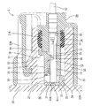
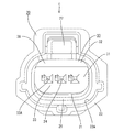
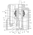
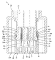
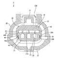
以下、本発明を具体化した一実施形態について、図1〜図12を参照しつつ詳細に説明する。
本実施形態における防水コネクタは、雌型のコネクタCであって、複数の端子金具10を収容するハウジング20を有している。以下、各構成部材において、図1における左側(このコネクタCの相手側コネクタ50との嵌合面側)を前方とし、また、上側を上方、下側を下方として説明する。
Hereinafter, an embodiment embodying the present invention will be described in detail with reference to FIGS.
The waterproof connector in the present embodiment is a female connector C and has a
端子金具10は、雌型の端子金具10であって、所定形状に打ち抜いた金属板を曲げ加工することで形成され、その前端側には相手側の雄端子のタブ51が挿入接続される箱型の接続部11を備えるとともに、後端側にはバレル部12を備え、このバレル部12に電線13の端末が圧着されている。
The
ハウジング20は合成樹脂製であり、端子金具10を収容する端子収容部21と、この端子収容部21の周りを囲って前方に開口するフード部22とを有している。
端子収容部21は若干横長断面の柱状をなし、この端子収容部21内には、端子金具10を収容可能なキャビティ23が3個、幅方向に並んで形成されている。各キャビティ23は前後方向に貫通し、後方から端子金具10を挿入可能とされている。各キャビティ23内における天井面には、端子金具10を一次係止するランス24が前方に向かって片持ち状に延出されている。このランス24の上方には、ランス24の上方への撓み変形を許容する撓み空間S1が形成されている。
The
The terminal accommodating
また、キャビティ23の天井面には、後述するリテーナ30の端子係止部36が上方から挿入される挿入孔25が形成されている。挿入孔25は、キャビティ23に収容された端子金具10の接続部11の後側に形成されている。挿入孔25は、各キャビティ23の幅方向略中央位置に設けられて、前後方向に細長い長方形状をなして上下に開口している。
In addition, an
端子収容部21のうちキャビティ23に収容された端子金具10のバレル部12の上方に配される部分は、上下方向の厚さ寸法が他の部分よりも大きい壁厚部21Aとされている。この壁厚部21Aにより、挿入孔25の後端位置には、後側が高い段差が形成されている。
A portion of the
また、端子収容部21の外周面には、ハウジング20と相手側コネクタ50のスカート部52との間をシールするシールリング26が嵌着されている。シールリング26は、端子収容部21のうち壁厚部21Aが形成された部分の外周面に装着されている。
A
フード部22は、端子収容部21から外側に向かって突出され、さらにその突出端が前方に向かって延出されて、全体として有底の筒状をなしている。そして、フード部22の内周面と端子収容部21の外周面との間には、相手側コネクタ50が嵌合する嵌合空間S2が形成されている。嵌合空間S2には、相手側コネクタ50のスカート部52が進入可能とされている。なお、フード部22の上面には窓部22Bが切り欠き形成され、この窓部22B内には、相手側コネクタ50との間を嵌合状態にロックするためのロックアーム27が形成されている。
The
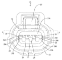
ハウジング20には、後述するリテーナ30を仮係止位置に保持する仮係止突起28と、本係止位置に保持する本係止突起29とが設けられている。仮係止突起28および本係止突起29は、図2に示すように、端子収容部21の幅方向の両側面に一対ずつ設けられ、それぞれ端子収容部21の側面から側方に突出する形状をなしている。
The
仮係止突起28は、端子収容部21のうち端子金具10の接続部11が収容される部分の前後方向略中央位置において、端子収容部21の上下方向略中央位置、言い換えると、ランス24と幅方向に並ぶ高さ位置に設けられている。仮係止突起28の前面は、前端から後方に向かって少しずつ端子収容部21からの突出寸法が大きくなる緩い傾斜をなす仮係止案内面28Aとされている(図3参照)。また、仮係止突起28の後面は、リテーナ30の組み付け方向に対して略垂直をなす仮係止面28Bとされている。仮係止面28Bを前後方向から見ると、上下方向に長い略長方形をなしている。
The
本係止突起29は、仮係止突起28の後方位置において、仮係止突起28から下方に離間した位置に設けられている。本係止突起29は、突出端に向かって上下方向の幅寸法が小さくなる山型断面をなして前後方向に延びている。本係止突起29の上面は、突出端に向かって下方に下がる傾斜をなす本係止案内面29Aとされている(図2参照)。また、本係止突起29の下面は、突出端に向かって上方に上る傾斜をなす本係止面29Bとされている。本係止案内面29Aは、上下方向に対する傾きの程度が本係止面29Bよりも緩く設定されている。なお、本係止突起29の前後両端面も、端子収容部21の側面に対して傾く傾斜面とされている。
The
防水コネクタCは、ハウジング20に対して前方(フード部22の開口22A)から組み付けられるフロントタイプのリテーナ30を備えている。このリテーナ30は合成樹脂製であって、端子収容部21の前方に配されて端子金具10の前止まりとなる前止め部31と、端子収容部21の上面側に配されて端子金具10の抜け止めを図る抜止め部32とを有している。リテーナ30は、端子金具10の挿抜を許容する仮係止位置(図8参照)と、端子金具10の挿抜を規制する本係止位置(図11参照)との間を移動可能とされている。リテーナ30は、前方から端子収容部21に組み付けられて仮係止位置に保持され、仮係止位置から下方(嵌合方向と交差する方向)へ押されることで本係止位置に移動するようになっている。
The waterproof connector C includes a
前止め部31は、全体として端子収容部21の前方を覆うキャップ状をなしている。前止め部31は、端子収容部21の前面と対向する前壁33と、前壁33の周縁から後方に突出する周壁34と、前壁33から後方に突出して各キャビティ23間を仕切る仕切り壁35とを有している(図4および図5参照)。前壁33には、各キャビティ23と対応した位置ごとに、相手側の雄端子のタブ51が挿入される端子挿入口33Aが開口している。また、周壁34のうち各キャビティ23の上方位置には、周壁34を壁厚方向に貫通する貫通口37が形成されている。
The
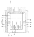
抜止め部32は、前止め部31の上縁から後方へ向かって張り出している。抜止め部32は、全体として平らな板状をなし、端子収容部21の上面のうち壁厚部21Aよりも前側の部分に配置される。抜止め部32は、リテーナ30が仮係止位置にあるときにはランス24の撓み空間S1から上方に退避して配され(図8参照)、本係止位置にあるときには撓み空間S1に進入してランス24の上面に近接して配され、ランス24の撓み変形を規制する。
The retaining
抜止め部32の後端寄りの位置には、下方に突出する端子係止部36(本発明の係止部に該当する)が設けられている。端子係止部36は、各キャビティ23に対応する位置に設けられ、それぞれ挿入孔25に挿入可能な形状をなしている。端子係止部36は、リテーナ30が仮係止位置にあるときにはキャビティ23から上方に退避して配され(図8および図10参照)、本係止位置にあるときにはキャビティ23内に突出して、端子金具10の接続部11に対して後方から二次係止する(図11および図12参照)。
A terminal locking portion 36 (corresponding to the locking portion of the present invention) protruding downward is provided at a position near the rear end of the retaining
抜止め部32の後端には、リテーナ30が仮係止位置にあるときに、相手側コネクタ50のスカート部52が突き当たる突当部38が設けられている。突当部38は、端子収容部21の壁厚部21Aの前端に沿って立ち上がる形状をなし、その立ち上り端は、壁厚部21Aの上面に沿って後方へ張り出す形状をなしている(この張り出し部分を張出部39と称する)。突当部38は、リテーナ30が仮係止位置にあるときには嵌合空間S2に突出し、張出部39が壁厚部21Aから上方へ離れた位置に配される(図8参照)。また、突当部38は、リテーナ30が本係止位置にあるときには嵌合空間S2から下方へ退避し、張出部39が壁厚部21Aの上面に近接して配され、シールリング26の前側に位置してシールリング26の抜け止めを図る(図11参照)。
A rear end of the retaining
リテーナ30は、ハウジング20の仮係止突起28および本係止突起29に係止して、リテーナ30を仮係止位置または本係止位置に保持する保持部40を有している。
The
保持部40は、前壁33の両側縁から後方に突出するとともに、抜止め部32の両側縁から下方へ垂下する形状をなし、それぞれ端子収容部21の側方に嵌合するようになっている。
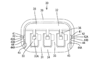
一対の保持部40の内面(対向面)には、第1溝部41がそれぞれ形成されている。第1溝部41は、図4に示すように、保持部40の上下方向略中央位置に形成されて前後方向に延びる溝状をなしている。第1溝部41は後方に開放された形態をなし、ハウジング20の仮係止突起28が後方から嵌合可能とされている。
The holding
第1溝部41の前後方向略中間位置には、仮係止突起28と係止する第1係止部42が設けられている。第1係止部42は、第1溝部41を幅方向(上下方向)に横切る壁状をなし、その後面は、前方に向かって少しずつ上る傾斜をなす第1案内面42Aとされている。また、第1係止部42の前面は、第1溝部41に対して略垂直をなす第1係止面42Bとされている。
A
第1溝部41のうち第1係止部42よりも前側の部分は、後側の部分よりも上方に幅が広がった形状をなし、その広がった部分は、第1係止部42に係止した仮係止突起28の上方への移動を許容する逃がし部43とされている。
A portion of the
第1溝部41の下側には、前後方向に延びる第2係止部44が形成されている。第2係止部44は、第1溝部41の下縁に沿って、その前後方向の全長にわたり延びる突条である。第2係止部44は、ハウジング20の仮係止突起28と本係止突起29との間の隙間に嵌合可能な断面形状をなしている。第2係止部44の下面は、上方に向かって少しずつ突出寸法が大きくなる傾斜をなす第2案内面44Aとされている。第2案内面44Aは、本係止突起29の本係止案内面29Aと同等の勾配とされている。また、第2係止部44の上面は、第1溝部41に対して略垂直をなす第2係止面44Bとされている。なお、第2係止部44の後端面は、前方に向かって少しずつ突出寸法が大きくなる傾斜をなしている。
A
第2係止部44の下側には、第2係止部44の下縁に沿って前後方向に延びる第2溝部45が設けられている。第2溝部45は、第1溝部41と同等の深さ寸法とされている。第2溝部45は、第2係止部44の前後方向の全長にわたる長さ寸法を有するとともに、後方へ開放された形態をなし、後方からハウジング20の本係止突起29が嵌合可能とされている。
A
次に、コネクタCの組み付け方法について説明する。
コネクタCを組み付ける際には、ハウジング20の端子収容部21にシールリング26を嵌着した後、リテーナ30を仮係止位置に保持させる。まず、フード部22の開口22Aからリテーナ30をフード部22内に進入させ、第1溝部41が端子収容部21の仮係止突起28に嵌合するよう位置合わせして後方へ押し込む。すると、第1溝部41が仮係止突起28に嵌合し、第1係止部42の第1案内面42Aと仮係止突起28の仮係止案内面28Aとが当接する。さらにリテーナ30を後方へ押し込むと、第1案内面42Aおよび仮係止案内面28Aの傾斜に案内されることで、第1係止部42が仮係止突起28に乗り上がり、それに伴って保持部40が外側に弾性変形する。やがて第1係止部42は仮係止突起28を乗り越えて第1溝部41の奥側に嵌合し、保持部40が内側に弾性復帰する(図9参照)。そして、第1係止部42の第1係止面42Bと仮係止突起28の仮係止面28Bとが前後方向に対向して係止し、リテーナ30の前方への離脱が規制された状態になる。また、本係止突起29が第2溝部45の後端部に嵌合して本係止突起29と仮係止突起28とが第2係止部44を上下方向に挟んだ状態になり、リテーナ30の上下方向の変位が規制された状態になる。また、抜止め部32の後端が、端子収容部21の壁厚部21Aの前端に近接・または当接した状態になり、リテーナ30の後方への移動が規制された状態になる。こうして、リテーナ30が仮係止位置に保持される。ここで、誤ってコネクタCを相手側コネクタ50と嵌合させようとしたときには、相手側コネクタ50のスカート部52がリテーナ30の突当部38に突き当たる。そして、リテーナ30は後方への移動を規制されているから、それ以上相手側コネクタ50との嵌合を進めることはできず、相手側コネクタ50と無理に嵌合してしまう事態を防ぐことができる。
Next, a method for assembling the connector C will be described.
When the connector C is assembled, the
次に、端子金具10をキャビティ23内に挿入する。キャビティ23内に挿入された端子金具10は、途中でランス24を上方へ撓み変形させつつ、さらに押し込まれる。この端子金具10が所定位置まで挿入されると、ランス24が弾性復元してその前端部が端子金具10の接続部11の上壁に係合し、これにより端子金具10が抜止め状態に一次係止される。
Next, the terminal fitting 10 is inserted into the
こうして、すべての端子金具10をキャビティ23内に収容した後、リテーナ30を下方へ押し込む。すると、第2係止部44の第2案内面44Aと本係止突起29の本係止案内面29Aとが強く当接して、両案内面44A,29Aの傾斜に案内されることで、第2係止部44は本係止突起29に乗り上がり、それに伴って保持部40は外側に弾性変形する。やがて、第2係止部44は本係止突起29を乗り越えてその下方に嵌合し、図12に示すように、第2係止部44の第2係止面44Bと本係止突起29の本係止面29Bとが上下方向に対向して係止し、リテーナ30の上方への移動が規制された状態になる。また抜止め部32が端子収容部21の上面に当接して、リテーナ30の下方への移動が規制された状態になる。こうして、リテーナ30は本係止位置に保持され、リテーナ30の端子係止部36が端子金具10の接続部11に係止し、端子金具10が二重係止された状態になる。
Thus, after all the
次に、上記のように構成された本実施形態の作用および効果について説明する。
本実施形態のコネクタCは、ハウジング20に対して前方(フード部22の開口22A)から組み付けられて端子金具10の挿抜を許容する仮係止位置に保持され、仮係止位置から下方(嵌合方向と交差する方向)へ移動して端子金具10の挿抜を規制する本係止位置に至り、仮係止位置にあるときには嵌合空間S2内に位置し、本係止位置にあるときには嵌合空間S2から退避するリテーナ30を備えている。
Next, the operation and effect of the present embodiment configured as described above will be described.
The connector C of the present embodiment is assembled to the
このように、リテーナ30は、フード部22の開口22Aから組み付けられるから、フード部22の側面にリテーナ30を挿入するためのリテーナ挿入孔を設ける必要がないので、防水性を確保する点で有利である。また、リテーナ30は、仮係止位置にあるときには嵌合空間S2内に位置しているから、リテーナ30が仮係止位置にあるときに相手側コネクタ50を嵌合させようとすると、相手側コネクタ50がリテーナ30に突き当たる。そして、リテーナ30は、仮係止位置から下方へ移動して本係止位置に至るものであるから、相手側コネクタ50に前方から押されても本係止位置側に移動しないため、相手側コネクタ50が無理に嵌合することを防ぐことができる。したがって、本実施形態のコネクタCによれば、防水性を確保する点で有利で、かつリテーナ30が仮係止位置に保持された状態での相手側コネクタ50との無理な嵌合を防止することができる。
Thus, since the
また、リテーナ30は、前止め部31と抜止め部32とを一体に有しているから、例えば、端子金具10の前止まりとなる前壁部材と、端子金具10の抜け止めを図るリテーナ部材とを別体部品として有する場合に比べて、部品点数を少なくすることができ、もってコストの低減を図ることができる。
Further, since the
<他の実施形態>
本発明は上記記述及び図面によって説明した実施形態に限定されるものではなく、例えば次のような実施形態も本発明の技術的範囲に含まれる。
<Other embodiments>
The present invention is not limited to the embodiments described with reference to the above description and drawings. For example, the following embodiments are also included in the technical scope of the present invention.
(1)上記実施形態では、本発明を雌型のコネクタCに適用した例を説明したが、本発明は、雄側のコネクタに適用しても良い。
(1) In the above embodiment, the example in which the present invention is applied to the female connector C has been described. However, the present invention may be applied to a male connector.
C…防水コネクタ
S2…嵌合空間
10…端子金具
20…ハウジング
21…端子収容部
22…フード部
22A…フード部の開口
30…リテーナ
31…前止め部
36…端子係止部(係止部)
50…相手側コネクタ
C ... Waterproof connector S2 ...
50 ... Mating connector
Claims (1)
前記ハウジングに対して前記フード部の開口から組み付けられて前記端子金具の挿抜を許容する仮係止位置に保持され、前記仮係止位置から前記相手側コネクタとの嵌合方向と交差する方向へ移動して前記端子金具の挿抜を規制する本係止位置に至り、前記仮係止位置にあるときには前記嵌合空間内に位置し、前記本係止位置にあるときには前記嵌合空間から退避するリテーナと、を備え、
前記リテーナは、前記端子収容部の前記嵌合方向の前方に配されて前記端子金具の前止まりとなる前壁を有する前止め部と、
前記仮係止位置にあるときには前記端子金具から離間して同端子金具の挿抜を許容し、前記本係止位置にあるときには前記端子金具に係止して同端子金具の挿抜を規制する係止部が設けられるとともに前記端子収容部の一面側に配された抜け止め部と、
前記抜け止め部の前記嵌合方向の後方に設けられて前記端子収容部の外周面に設けられたシールリングの抜け止めを図る張出部と、
前記抜け止め部の前記端子収容部をはさんで反対側に配されるとともに前記前壁の周縁から前記嵌合方向の後方に突出する周壁と、を有する防水コネクタ。 A terminal housing portion that houses the terminal fitting, and a hood portion that surrounds the terminal housing portion and opens in a fitting direction with the mating connector, and between the terminal housing portion and the hood portion, A housing in which a fitting space into which the mating connector is fitted; and
It is assembled to the housing from the opening of the hood portion and is held at a temporary locking position that allows insertion and removal of the terminal fitting, and from the temporary locking position to a direction crossing the fitting direction with the mating connector. It moves to a final locking position that restricts insertion / extraction of the terminal fitting, is located in the fitting space when in the temporary locking position, and retracts from the fitting space when in the final locking position. includes a retainer, the,
The retainer is disposed in front of the terminal accommodating portion in the fitting direction, and has a front stop portion having a front wall that becomes a front stop of the terminal fitting,
When in the temporary locking position, the terminal fitting is separated from the terminal fitting to allow insertion / extraction, and when in the main locking position, the terminal fitting is locked to the terminal fitting to restrict insertion / extraction of the terminal fitting. And a retaining portion disposed on one side of the terminal accommodating portion,
An overhang portion that is provided behind the retaining portion in the fitting direction and that prevents the seal ring from being detached from the outer peripheral surface of the terminal accommodating portion;
A waterproof connector having a peripheral wall disposed on the opposite side of the terminal accommodating portion of the retaining portion and protruding rearward from the periphery of the front wall in the fitting direction .
Priority Applications (1)
| Application Number | Priority Date | Filing Date | Title |
|---|---|---|---|
| JP2009084879A JP5218213B2 (en) | 2009-03-31 | 2009-03-31 | Waterproof connector |
Applications Claiming Priority (1)
| Application Number | Priority Date | Filing Date | Title |
|---|---|---|---|
| JP2009084879A JP5218213B2 (en) | 2009-03-31 | 2009-03-31 | Waterproof connector |
Publications (2)
| Publication Number | Publication Date |
|---|---|
| JP2010238514A JP2010238514A (en) | 2010-10-21 |
| JP5218213B2 true JP5218213B2 (en) | 2013-06-26 |
Family
ID=43092670
Family Applications (1)
| Application Number | Title | Priority Date | Filing Date |
|---|---|---|---|
| JP2009084879A Expired - Fee Related JP5218213B2 (en) | 2009-03-31 | 2009-03-31 | Waterproof connector |
Country Status (1)
| Country | Link |
|---|---|
| JP (1) | JP5218213B2 (en) |
Cited By (1)
| Publication number | Priority date | Publication date | Assignee | Title |
|---|---|---|---|---|
| JP2012113987A (en) * | 2010-11-25 | 2012-06-14 | Sumitomo Wiring Syst Ltd | Waterproof connector |
Families Citing this family (4)
| Publication number | Priority date | Publication date | Assignee | Title |
|---|---|---|---|---|
| JP5987795B2 (en) * | 2013-07-16 | 2016-09-07 | 住友電装株式会社 | connector |
| JP7178879B2 (en) * | 2018-11-13 | 2022-11-28 | 日本航空電子工業株式会社 | connector |
| JP7131776B2 (en) * | 2019-02-18 | 2022-09-06 | 日本圧着端子製造株式会社 | connector |
| JP7528877B2 (en) | 2021-06-29 | 2024-08-06 | 株式会社オートネットワーク技術研究所 | connector |
Family Cites Families (2)
| Publication number | Priority date | Publication date | Assignee | Title |
|---|---|---|---|---|
| JPH1064625A (en) * | 1996-08-21 | 1998-03-06 | Sumitomo Wiring Syst Ltd | Connector |
| JP4070126B2 (en) * | 2003-10-20 | 2008-04-02 | 矢崎総業株式会社 | connector |
-
2009
- 2009-03-31 JP JP2009084879A patent/JP5218213B2/en not_active Expired - Fee Related
Cited By (1)
| Publication number | Priority date | Publication date | Assignee | Title |
|---|---|---|---|---|
| JP2012113987A (en) * | 2010-11-25 | 2012-06-14 | Sumitomo Wiring Syst Ltd | Waterproof connector |
Also Published As
| Publication number | Publication date |
|---|---|
| JP2010238514A (en) | 2010-10-21 |
Similar Documents
| Publication | Publication Date | Title |
|---|---|---|
| JP4924454B2 (en) | connector | |
| CN108346891B (en) | Connector with a locking member | |
| JP6195165B2 (en) | connector | |
| JP4839989B2 (en) | connector | |
| US8747154B2 (en) | Waterproof connector | |
| US8708739B2 (en) | Connector | |
| US20140127928A1 (en) | Connector | |
| JP2009181722A (en) | Connector | |
| JP5218213B2 (en) | Waterproof connector | |
| JP4238746B2 (en) | connector | |
| JP5682476B2 (en) | connector | |
| JP6176544B2 (en) | connector | |
| JP2014093221A (en) | Connector | |
| JP5093088B2 (en) | Waterproof connector | |
| JP4457987B2 (en) | connector | |
| JP6292468B2 (en) | connector | |
| WO2020116112A1 (en) | Connector | |
| JP4483529B2 (en) | connector | |
| JP4544065B2 (en) | connector | |
| JP2011071061A (en) | Split connector | |
| JP5375739B2 (en) | connector | |
| JP4636072B2 (en) | connector | |
| JP3755433B2 (en) | connector | |
| JP2017199597A (en) | connector | |
| JP3755432B2 (en) | connector |
Legal Events
| Date | Code | Title | Description |
|---|---|---|---|
| A621 | Written request for application examination |
Free format text: JAPANESE INTERMEDIATE CODE: A621 Effective date: 20110802 |
|
| A977 | Report on retrieval |
Free format text: JAPANESE INTERMEDIATE CODE: A971007 Effective date: 20121029 |
|
| A131 | Notification of reasons for refusal |
Free format text: JAPANESE INTERMEDIATE CODE: A131 Effective date: 20121101 |
|
| A521 | Written amendment |
Free format text: JAPANESE INTERMEDIATE CODE: A523 Effective date: 20121218 |
|
| TRDD | Decision of grant or rejection written | ||
| A01 | Written decision to grant a patent or to grant a registration (utility model) |
Free format text: JAPANESE INTERMEDIATE CODE: A01 Effective date: 20130205 |
|
| A61 | First payment of annual fees (during grant procedure) |
Free format text: JAPANESE INTERMEDIATE CODE: A61 Effective date: 20130218 |
|
| FPAY | Renewal fee payment (event date is renewal date of database) |
Free format text: PAYMENT UNTIL: 20160315 Year of fee payment: 3 |
|
| R150 | Certificate of patent or registration of utility model |
Free format text: JAPANESE INTERMEDIATE CODE: R150 |
|
| LAPS | Cancellation because of no payment of annual fees |
