JP5217860B2 - Blind spot image display device and blind spot image display method - Google Patents
Blind spot image display device and blind spot image display method Download PDFInfo
- Publication number
- JP5217860B2 JP5217860B2 JP2008255037A JP2008255037A JP5217860B2 JP 5217860 B2 JP5217860 B2 JP 5217860B2 JP 2008255037 A JP2008255037 A JP 2008255037A JP 2008255037 A JP2008255037 A JP 2008255037A JP 5217860 B2 JP5217860 B2 JP 5217860B2
- Authority
- JP
- Japan
- Prior art keywords
- blind spot
- imaging
- spot image
- image
- camera
- Prior art date
- Legal status (The legal status is an assumption and is not a legal conclusion. Google has not performed a legal analysis and makes no representation as to the accuracy of the status listed.)
- Active
Links
Images


Description
本発明は、車両に設けられた撮像装置で自車両の死角を撮影して得られた死角画像を乗員に提示する死角画像表示装置ならびに死角画像表示方法に関する。 The present invention relates to a blind spot image display apparatus and a blind spot image display method for presenting a blind spot image obtained by photographing a blind spot of an own vehicle to an occupant with an imaging device provided in the vehicle.
従来、この種の技術としては、例えば以下に示す文献に記載されたものが知られている(特許文献1参照)。この文献に記載された技術では、見通しの悪い交差点等で乗員によるスイッチ等の操作によりモニタに死角画像を表示する(ブラインドモニタ(死角画像表示装置)を作動させる)と、この場所のリンク番号、走行方向、交差点までの距離を記憶した後、次回以降に車両がこの場所を走行して、この走行路のリンク番号、走行方向ならびに交差点までの距離が前回の記憶情報と一致し、かつ車速が所定の値以下であると、ブラインドモニタを自動的に作動させるようにしている。
上記従来のブラインドモニタにおいては、モニタに死角画像を表示させる初回の場所では、乗員による操作が必要となり、煩わしいという問題点があった。 The conventional blind monitor has a problem that it is troublesome and requires an operation by a passenger at the first place where the blind spot image is displayed on the monitor.
そこで、本発明は、上記に鑑みてなされたものであり、その目的とするところは、乗員操作を要することなく死角画像を表示することを可能にした死角画像表示装置ならびに死角画像表示方法を提供することにある。 Therefore, the present invention has been made in view of the above, and an object of the present invention is to provide a blind spot image display device and a blind spot image display method capable of displaying a blind spot image without requiring an occupant operation. There is to do.
上記目的を達成するために、フロントグリルに設置された第1の撮像手段で撮像された前記自車両の前方左側方及び前方右側方の少なくとも一方の画像と、サイドミラーに設置された第2の撮像手段で撮像された、前記第1の撮像手段で撮像する撮像領域の一部と少なくとも重複する前方側方の画像との一致度合いを判別し、判別の結果、両画像の一致度合いが予め設定された一致度合いよりも低いと判別された場合には、前記第1の撮像手段で撮像された死角画像を前記表示手段に表示することを特徴とする。 In order to achieve the above object, at least one of the front left side and front right side images of the host vehicle imaged by the first imaging means installed on the front grille and a second side installed on the side mirror The degree of coincidence between a part of the imaging area imaged by the first imaging unit and at least the front side image that has been imaged by the imaging unit is determined, and as a result of the determination, the degree of coincidence of both images is preset If it is determined to be lower than the degrees that are is characterized by displaying a blind spot image captured by the first imaging hand stage on the display means.
本発明によれば、見通しの悪い交差点などで自動的に死角画像が表示されるので、乗員による操作を要することなく、死角画像を表示することができる。 According to the present invention, since a blind spot image is automatically displayed at an intersection with poor visibility, the blind spot image can be displayed without requiring an operation by a passenger.
以下、図面を用いて本発明を実施するための最良の実施例を説明する。 DESCRIPTION OF THE PREFERRED EMBODIMENTS The best embodiment for carrying out the present invention will be described below with reference to the drawings.
図1は本発明の実施例1に係る死角画像表示装置の構成を示す図である。図1に示す実施例1の死角画像表示装置は、自車両の周囲を撮影する複数のカメラ11(11a,11b)と、これらのカメラ11による撮像で得られた画像データを処理、表示制御する画像処理制御装置12と、この画像処理制御装置12で得られた画像を表示するモニタ13とを備えて構成されている。
FIG. 1 is a diagram illustrating a configuration of a blind spot image display device according to a first embodiment of the present invention. The blind spot image display device of Example 1 shown in FIG. 1 processes and controls display of a plurality of cameras 11 (11a, 11b) that capture the surroundings of the host vehicle and image data obtained by imaging with these cameras 11. The image
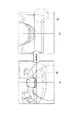
カメラ11aは、自車両のフロントグリル中央に設置され、図2に符号Aで示すように、カメラ11aが設置された自車両20のフロントグリル中央を中心に左右対称となる前方ならびに前方左右側方を撮像する。この撮像範囲には、自車両20の前方左右の運転者にとって視認が困難な死角となる死角領域が含まれる。したがって、死角画像表示装置は、カメラ11aで撮像された死角領域の画像を含む撮像画像を表示する。
The
カメラ11bは、自車両20の左右のドアミラーに設置され、左ドアミラーに設置されたカメラ11bは、図2の符号Bで示すように、自車両20の左側斜め前方を撮像し、右ドアミラーに設置されたカメラ11bは、図示されていないが自車両20の前後の中心線を中心に左のドアミラーに設置されたカメラ11bの撮像領域と左右対称となる自車両20の右側斜め前方を撮像する。なお、以下の説明では、カメラ11aと左ドアミラーに設置されたカメラ11bとの撮像領域について説明するが、カメラ11aと右ドアミラーに設置されたカメラ11bとの撮像領域についても同様である。
The
ここで、カメラ11aの撮像領域Aと左ドアミラーに設置されたカメラ11bの撮像領域Bとが重複する重複撮像領域とは、図2の符号Cで示す領域(斜線で示す領域)を指すものとし、以下に説明する交差点における見通しが良好が否かを判断するために予め設定される特定領域とは、上記重複撮像領域C内の所定の領域に設定され、図2の符号Dで示す領域(交斜線で示す領域)として設定される。
Here, the overlapping imaging area in which the imaging area A of the
これらのカメラ11a、11bは、例えばCCDカメラやCMOSカメラ等で構成され、撮像で得られた画像データは、画像処理制御装置12に与えられる。
These
画像処理制御装置12は、各カメラ11の撮像で得られた画像データを受けて、この画像データを画像処理し、得られた画像をモニタ13に表示する。画像処理制御装置12は、カメラ11aの撮像で得られた画像データに対して、画像処理技術の分野で従来公知の画像処理技術の内、画像内のオブジェクトの輪郭を抽出するエッジ検出処理を施し、走行路においるガードレールの有無を判定する。すなわち、画像処理制御装置12は、カメラ11aで得られた画像の内、予め設定された領域に対してエッジ抽出を行う際に適用されるしきい値を用いてエッジを抽出し、抽出したエッジが先に設定した特定領域を2つに分割するものであるか否かを判別し、2つに分割するものであるならば走行路にガードレールが設置されているものと判別する。ガードレールが設置されている場合には、ブラインドモニタを起動せずに、従来周知のナビゲーションシステム14によって経路案内等の画面がモニタ13の画面に表示される。
The image
画像処理制御装置12は、カメラ11aの撮像で得られた画像データとカメラ11bの撮像で得られた画像データとを比較して、両画像データの一致度合いを算出する。すなわち、画像処理制御装置12は、既述した図2に示すカメラ11aの撮像領域Aと左ドアミラーに設置されたカメラ11bの撮像領域Bとが重複した重複撮像領域C内に予め設定された特定領域Dにおける輝度の標準偏差等の統計量をそれぞれのカメラ11a、11bに対応した特定領域Dに対して算出し、カメラ11aに対応した統計量とカメラ11bに対応した統計量とを比較し、その差が予め設定された一致度合いの判別値以上か否かを判別し、判別結果によりそれぞれのカメラ11a、11bの特定領域Dの画像データにおける標準偏差等の統計量の一致度合いを判別し、一致度合いに基づいてカメラ11aで撮像された死角画像をモニタ13に表示するか否かを選択する。
The image
例えば、図2に示すように自車両20が交差点にさしかかったときに、同図(a)に示すように、カメラ11aの撮像領域Aとカメラ11bの撮像領域Bとが重複した重複撮像領域C内に設定された特定領域Dに対してそれぞれのカメラ11a,11b毎に算出された例えば標準偏差の差が予め設定された値以下である場合には、カメラ11aの撮像で得られた画像とカメラ11bで得られた撮像画像の両画像は概ね一致している(一致度合いは高い)ものと判別して、運転者から見て交差点の見通しは良好なものと判断し、死角画像をモニタ13に表示せずにモニタ13のそれまでの画面表示を継続する。
For example, when the host vehicle 20 approaches an intersection as shown in FIG. 2, as shown in FIG. 2A, an overlapping imaging area C in which the imaging area A of the
一方、同図(b)に示すように、それぞれのカメラ11a,11bに対応した特定領域Dの標準偏差の差が予め設定された値以上である場合には、カメラ11aの撮像で得られた画像とカメラ11bで得られた撮像画像の両画像は一致していない(一致度合いは低い)ものと判別して、運転者から見て交差点の見通しはよくないものと判断し、モニタ13の画面にカメラ11aで得られた自車両20の運転者に対して死角方向の死角画像を表示する。これは交差点の角に建物などが存在する場合には、カメラ11aは建物が写りこまないため、遠方範囲を直接撮像することになるが、カメラ11bでは建物が写りこむために、その建物より遠方の範囲はカメラ11bで撮像できないことになる。従って、両者の特定領域Dは異なる映像となり、標準偏差も異なり、よって一致度合いが低くなる。
On the other hand, when the difference in standard deviation of the specific area D corresponding to each of the
なお、カメラ11aとカメラ11bの両画像データの一致度合いを判別する手法としては、上記の他に例えば画像処理の技術分野で従来から一般的に広く知られているパターンマッチングの技術を適用して両画像データの一致度合いを判別するようにしてもよい。
As a method for determining the degree of coincidence between the image data of the
画像処理制御装置12は、プログラムに基づいて各種動作処理を制御するコンピュータに必要な、CPU、記憶装置、入出力装置等を備えた例えばマイクロコンピュータ、ASICやFPGAといった既存の特定用途向けの集積回路を含んで構成される。
The image
モニタ13は、車内の少なくとも運転者にとって画面が見やすい位置に設置され、ナビゲーションシステム14が起動されている場合には、経路案内等のナビゲーションシステム14から与えられる画像を表示して運転者に提示する一方、ブラインドモニタが起動された場合には、ナビゲーションシステム14から与えられる画像に優先させてカメラ11cで撮像された死角画像を表示して運転者に提示する。モニタ13は、CRTやLCDといった既存の表示装置で構成される。
The
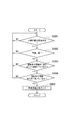
次に、図3のフローチャートを参照して、この実施例1における死角画像表示装置の動作手順について説明する。 Next, an operation procedure of the blind spot image display device according to the first embodiment will be described with reference to the flowchart of FIG.
図3を参照して、先ずカメラ11aの撮像領域A内に設定された特定領域Dに対して、画像処理技術のエッジ抽出手法ならびに抽出用のしきい値を適用してエッジを抽出する(ステップS301)。その後、抽出されたエッジが先の特定領域Dを2つに分割するか否かを判別する(ステップS302)。判別の結果、抽出されたエッジが領域を2つに分割する場合には、撮像領域にガードレールが存在するものと推定して、モニタ13に死角画像を表示せずに、例えばナビゲーションシステム14から与えられた、モニタ13の画面にそれまで表示されていた内容を継続して表示する(ステップS303)。
Referring to FIG. 3, first, an edge is extracted by applying an edge extraction method of image processing technology and an extraction threshold value to a specific area D set in the imaging area A of the
一方、判別結果において、抽出したエッジが領域を2つに分割していない場合には、続いてカメラ11aの画像データの内特定領域Dの画像データにおける輝度の標準偏差(Laσ)を算出する(ステップS304)。同様に、カメラ11bの画像データの内特定領域Dの画像データにおける輝度の標準偏差(Lbσ)を算出する(ステップS305)。
On the other hand, if the extracted edge does not divide the area into two in the determination result, the standard deviation (Laσ) of the luminance in the image data of the specific area D of the image data of the
次に、上記両標準偏差の差の絶対値が、予め設定された一致度合いの判定値(α)よりも大きいか否かを判別する(ステップS306)。判別の結果、大きくない場合には、上記特定領域Dの両画像データは概ね一致して一致度合いは高いものと判別し、運転者にとって交差点等の見通しはよいものと推定し、モニタ13に死角画像を表示せずにモニタ13のそれまでの画面表示(例えばナビゲーション画面)を継続する(ステップS307)。
Next, it is determined whether or not the absolute value of the difference between the two standard deviations is greater than a preset determination value (α) for the degree of coincidence (step S306). If the result of determination is not large, it is determined that the two image data in the specific area D are substantially coincident and the degree of coincidence is high, and it is presumed that the driver has a good view of an intersection or the like. The screen display (for example, navigation screen) until then on the
一方、判別の結果、大きい場合には、運転者にとって交差点等の見通しはよくないもの(運転者が死角画像の表示を必要としているもの)と推定して、それまで表示されていた画面表示に代えてカメラ11aの撮像で得られた死角画像をモニタ13に表示する(ステップS308)。
On the other hand, if the result of the determination is large, it is assumed that the driver has a poor view of the intersection or the like (the driver needs to display the blind spot image), and the screen display that has been displayed so far is displayed. Instead, a blind spot image obtained by imaging with the
なお、モニタ13に死角画像を表示するか否かにおいて、図4に示すように、自車両の車速や自車両が交差点付近を走行しているか否かの情報の要件を加えるようにしてもよい。すなわち、ナビゲーションシステム14で用いられる車速が予め設定された速度以下(要件1)であればモニタ13に死角画像を表示し、あるいは要件1に加えて、ナビゲーションシステム14が備えている地図情報から得られる自車両の位置が交差点付近である(要件2)場合にはモニタ13に死角画像を表示し、もしくは要件1、要件2に加えて、上記実施例1の要件が満たされた場合にモニタ13に死角画像を表示するようにしてもよい。
Whether or not the blind spot image is displayed on the
このように、上記実施例1においては、交差点等の見通しがよくないことを判別して運転者が死角画像の表示を必要とするであろうことを事前に判断し、その判断結果に基づいてモニタ13に死角画像を表示するようにしたので、乗員による起動操作を行うことなく的確にモニタ13に死角画像を表示することができる。これにより、乗員による表示操作や、モニタ13に死角画像を表示させる場所を事前に登録するといった登録作業は不要となり、煩わしさを低減することができる。
As described above, in the first embodiment, it is determined in advance that the driver is required to display the blind spot image by determining that the prospect of the intersection or the like is not good, and based on the determination result. Since the blind spot image is displayed on the
また、見通しのよい交差点等の本来死角画像の表示が不要な場所でモニタ13に死角画像を表示することは抑制される。これにより、ナビゲーションシステム14から与えられる経路案内等の、現時点でモニタ13に死角画像を表示することよりも運転者にとって必要性の高い情報をモニタ13に表示して提示することが可能となり、利用者の意図と一致させることができる。
In addition, the display of the blind spot image on the
次に、本発明の実施例2について説明する。この実施例2の特徴とするところは、俯瞰画像を用いて、先の実施例1で採用した輝度の標準偏差やパターンマッチングにより画像データの一致度を算出するようにしたことにあり、他は先の実施例1と同様である。 Next, a second embodiment of the present invention will be described. The feature of the second embodiment is that the degree of coincidence of the image data is calculated by the standard deviation of brightness and the pattern matching employed in the previous first embodiment using the overhead image. This is the same as in the first embodiment.
上記特徴的な技術を実現するにあたって、画像処理制御装置12は、カメラ11a、11bで撮像されて得られた画像データに基づいて、両画像にそれぞれ対応した俯瞰画像を生成する。この俯瞰画像は、例えば従来から知られている視点変換の技術を用いる。この視点変換の画像処理の技術は、例えば特開2000−33901号公報に記載された車両用画像表示システムで採用されており、車両周囲の所定の領域を撮像するカメラで得られた実画像を、所定の仮想視点例えば車両上方からみた仮想画像に変換する技術である。具体的には、例えば視点変換後の仮想画像における出力画素の位置座標と、カメラの撮像で得られた実画像における入力画素の位置座標との対応関係を示す変換アドレス(マッピングテーブル)を予め用意し、このマッピングテーブルにしたがって入力画素の画素位置を変更して出力画像を生成することで、例えば車両上方に設定された仮想視点から俯瞰した俯瞰画像へと変換することをリアルタイムで実現している。
In realizing the above characteristic technique, the image
なお、カメラ11aとカメラ11bの設置位置が異なることにより両カメラの俯瞰画像の向きが異なるので、画像処理制御装置12では、一方の俯瞰画像の向きを他方の俯瞰画像の向きに一致させるように一方の俯瞰画像を回転させた後、両俯瞰画像をパターンマッチングにより比較している。
In addition, since the orientation of the overhead view image of both cameras differs because the installation positions of the
例えば図5(a)に示すように、カメラ11a、11bで撮像された画像において、符号50で示す領域を例えば先の実施例1で説明した特定領域Dに設定した場合に、この領域の画像は同図(a)に示すように歪んだ画像となり、かつその歪み具合は両カメラ間で異なるために、このような画像を用いて一致度を判定すると、判定精度が低下するおそれがある。
For example, as shown in FIG. 5A, when the area indicated by
これに対して、図5(b)に示すように、カメラ11a、11bの両実画像を上記視点変換技術を用いて俯瞰画像に変換することで、両俯瞰画像の形状が一致することになる。
On the other hand, as shown in FIG. 5B, by converting both real images of the
以上説明したように、実施例2においては、実施例1と同様の効果を有すると共に、俯瞰変換した画像を用いて一致度を判定するようにしたので、歪みの影響を受け難くなるために、一度の判定精度を高くすることができるという効果が得られる。 As described above, the second embodiment has the same effect as the first embodiment, and the degree of coincidence is determined using the overhead-converted image. The effect that the accuracy of determination once can be increased is obtained.
次に、本発明の実施例3について説明する。図6はこの実施例3に係る死角画像表示装置の構成を示す図である。 Next, Embodiment 3 of the present invention will be described. FIG. 6 is a diagram illustrating the configuration of the blind spot image display device according to the third embodiment.
この実施例3は、先に説明した実施例1もしくは実施例2の構成にカメラ11cを加え、画像処理装置12は、先の実施例1で説明したカメラ11aとカメラ11bとの両画像データにおける一致度合いの判別結果に優先させて、カメラ11cの撮像で得られた画像に基づいて運転者の視線移動が検出された場合にはモニタ13に死角画像を表示する機能を加えている。
In the third embodiment, the
カメラ11cは、運転者の顔を撮像できる位置に設置され、運転者の視線の動きを検出できるように運転者の顔を撮像し、運転者の視線移動を検出する検出手段として機能する。カメラ11cの撮像で得られた画像データは画像処理制御装置12に与えられる。
The
画像処理制御装置12は、カメラ11cから与えられた画像データを解析して、運転者の視線移動を検出する。すなわち、自車両が交差点等にさしかかったときに運転者が左右の安全を確認するために、例えば図7(a)に示すように左右のAピラー71の方向に運転者72が視線を移動させたか否かを判別し、視線の移動を検出した場合には、続いて同図(b)に示すように運転者72がモニタ13の画面を視認するべくモニタ13が設置された方向に視線を移動させたか否かを判別し、視線の移動を検出した場合には、カメラ11aとカメラ11bとの両画像データにおける一致度合いの判別結果に優先させて、モニタ13に死角画像を表示する。
The image
次に、図8のフローチャートを参照して、実施例3における動作の手順を説明する。図8において、先ずナビゲーションシステム14が備えてる自車両の位置ならびに地図データとに基づいて、自車両の現在位置が交差点の付近か否かを判別する(ステップS801)。判別の結果、自車両が交差点付近を走行している場合には、続いてナビゲーションシステム14の機能から得られる自車両の速度が予め設定された車速、例えばモニタ13に死角画像を表示するに足る程度に低速であるか否かを判別する(ステップS802)。判別の結果、車速が設定された低速である場合には、続いて運転者の視線が左右のAピラーの方向に移動したか否かを判別する(ステップS803)。判別の結果、運転者の視線がAピラーの方向に移動した場合には、続いて運転者の視線がモニタ13の画面に移動したか否かを判別する(ステップS804)。判別の結果、運転者の視線がモニタ13の画面に移動した場合には、モニタ13に死角画像を表示する(ステップS805)。一方、視線移 以上説明したように、実施例3においては、実施例1と同様の効果を有すると共に、運転者が左右に視線を移動させたことを検出した場合に、モニタ13に死角画像を表示するようにしたので、的確に死角画像を表示することが可能となる。
Next, an operation procedure in the third embodiment will be described with reference to the flowchart of FIG. In FIG. 8, first, based on the position of the host vehicle and the map data provided in the
上記各実施例の構成要件と、特許請求の範囲における構成要件との対応関係は以下の通りである。すなわち、カメラ11aが第1の撮像手段を、カメラ11bが第2の撮像手段を、画像処理装置12が判別手段ならびに表示制御手段を、モニタ13が表示手段を構成する。
Correspondence between the configuration requirements of the above-described embodiments and the configuration requirements in the claims is as follows. That is, the
11a〜11d…カメラ
12…画像処理制御装置
13…モニタ
14…ナビゲーションシステム
11a to 11d ...
Claims (5)
フロントグリルに設置され、前記自車両の前方左側方及び前方右側方の少なくとも一方を撮像する第1の撮像手段と、
ドアミラーに設置され、前記第1の撮像手段で撮像する撮像領域の一部と少なくとも重複する前方側方を撮像する第2の撮像手段と、
前記第1の撮像手段で撮像された撮像領域と前記第2の撮像手段で撮像された撮像領域とが重複する重複撮像領域における、前記第1の撮像手段の画像と前記第2の撮像手段の画像との一致度合いを判別する判別手段と、
前記判別手段により両画像の一致度合いが予め設定された一致度合いよりも低いと判別された場合には、前記表示手段に前記第1の撮像手段で撮像された死角画像を表示する表示制御手段と
を有することを特徴とする死角画像表示装置。 In a blind spot image display device that displays on a display means a blind spot image obtained by imaging the blind spot of the host vehicle.
A first imaging means installed on a front grill for imaging at least one of a front left side and a front right side of the host vehicle;
A second imaging unit that is installed on the door mirror and that images a front side that overlaps at least a part of an imaging region captured by the first imaging unit;
The image of the first imaging unit and the second imaging unit in an overlapping imaging region where the imaging region imaged by the first imaging unit and the imaging region imaged by the second imaging unit overlap. A discriminating means for discriminating the degree of coincidence with the image;
Display control means for displaying a blind spot image captured by the first imaging means on the display means when the discrimination means determines that the matching degree of both images is lower than a preset matching degree; A blind spot image display device comprising:
ことを特徴とする請求項1に記載の死角画像表示装置。 The blind spot image display device according to claim 1, wherein the determination unit determines the degree of coincidence of the bird's-eye images obtained by bird's-eye conversion of the two images.
前記表示制御手段は、前記検出手段で運転者の視線の移動が検出された場合には、前記判別手段の判別結果に優先させて前記表示手段に死角画像を表示する
ことを特徴とする請求項1または2に記載の死角画像表示装置。 A detecting means for detecting the movement of the line of sight of the driver of the own vehicle;
The display control means displays a blind spot image on the display means in preference to a determination result of the determination means when a movement of the driver's line of sight is detected by the detection means. 3. A blind spot image display device according to 1 or 2.
ことを特徴とする請求項1,2及び3のいずれか1項に記載の死角画像表示装置。 The discriminating means calculates a standard deviation of luminance in an image of a specific area preset in the overlapping imaging area for each of the specific area of the first imaging means and the specific area of the second imaging means. 4. When the difference between the standard deviations of both luminances is larger than a preset discrimination value, it is judged that the degree of coincidence between the two images is low. The blind spot image display device described in 1.
フロントグリルに設置された第1の撮像手段で撮像された前記自車両の前方左側方及び前方右側方の少なくとも一方の画像と、サイドミラーに設置された第2の撮像手段で撮像された、前記第1の撮像手段で撮像する撮像領域の一部と少なくとも重複する前方側方の画像との一致度合いを判別し、
判別の結果、両画像の一致度合いが予め設定された一致度合いよりも低いと判別された場合には、前記前記表示手段に前記第1の撮像手段で撮像された死角画像を表示する
ことを特徴とする死角画像表示方法。 In a blind spot image display method for displaying on a display means a blind spot image obtained by imaging a blind spot of the host vehicle,
At least one image of the front left side and the front right side of the host vehicle imaged by the first imaging unit installed on the front grille and the second imaging unit installed on the side mirror, Determining the degree of coincidence between at least a part of the imaging region imaged by the first imaging means and the front side image overlapping ,
Result of the determination, when the degree of matching between the images is determined to be lower than the degrees that is set in advance, displaying a blind spot image captured by the first imaging hands stage the said display means A blind spot image display method as a feature.
Priority Applications (1)
| Application Number | Priority Date | Filing Date | Title |
|---|---|---|---|
| JP2008255037A JP5217860B2 (en) | 2008-09-30 | 2008-09-30 | Blind spot image display device and blind spot image display method |
Applications Claiming Priority (1)
| Application Number | Priority Date | Filing Date | Title |
|---|---|---|---|
| JP2008255037A JP5217860B2 (en) | 2008-09-30 | 2008-09-30 | Blind spot image display device and blind spot image display method |
Publications (2)
| Publication Number | Publication Date |
|---|---|
| JP2010087861A JP2010087861A (en) | 2010-04-15 |
| JP5217860B2 true JP5217860B2 (en) | 2013-06-19 |
Family
ID=42251358
Family Applications (1)
| Application Number | Title | Priority Date | Filing Date |
|---|---|---|---|
| JP2008255037A Active JP5217860B2 (en) | 2008-09-30 | 2008-09-30 | Blind spot image display device and blind spot image display method |
Country Status (1)
| Country | Link |
|---|---|
| JP (1) | JP5217860B2 (en) |
Families Citing this family (1)
| Publication number | Priority date | Publication date | Assignee | Title |
|---|---|---|---|---|
| JP2019151304A (en) * | 2018-03-06 | 2019-09-12 | アイシン精機株式会社 | Periphery monitoring device |
Family Cites Families (3)
| Publication number | Priority date | Publication date | Assignee | Title |
|---|---|---|---|---|
| JP4275507B2 (en) * | 2003-10-28 | 2009-06-10 | 富士通テン株式会社 | Driving assistance device |
| JP2007045336A (en) * | 2005-08-10 | 2007-02-22 | Sumitomo Electric Ind Ltd | System and method for detecting obstacle |
| JP4662832B2 (en) * | 2005-09-26 | 2011-03-30 | アルパイン株式会社 | Image display device for vehicle |
-
2008
- 2008-09-30 JP JP2008255037A patent/JP5217860B2/en active Active
Also Published As
| Publication number | Publication date |
|---|---|
| JP2010087861A (en) | 2010-04-15 |
Similar Documents
| Publication | Publication Date | Title |
|---|---|---|
| JP5013184B2 (en) | Driving support device and computer program | |
| EP2487906B1 (en) | Control device and vehicle surrounding monitoring device | |
| JP4412380B2 (en) | Driving support device, driving support method, and computer program | |
| US8330816B2 (en) | Image processing device | |
| JP5136950B2 (en) | In-vehicle device operation device | |
| JP5286035B2 (en) | Vehicle speed control device | |
| JP4366716B2 (en) | Vehicle information display device | |
| WO2017046937A1 (en) | Display apparatus for vehicle and display method for vehicle | |
| US20080246843A1 (en) | Periphery monitoring system for vehicle | |
| JP6459205B2 (en) | Vehicle display system | |
| JP6379779B2 (en) | Vehicle display device | |
| US20130300872A1 (en) | Apparatus and method for displaying a blind spot | |
| JP4222183B2 (en) | Vehicle peripheral image display device | |
| JP2005182306A (en) | Vehicle display device | |
| US10866416B2 (en) | Display control device and display control method | |
| JP2008280026A (en) | Driving assistance device | |
| KR20150051665A (en) | Apparatus and Method for Assisting Parking | |
| WO2013161028A1 (en) | Image display device, navigation device, image display method, image display program and recording medium | |
| CN107004250B (en) | Image generation device and image generation method | |
| JP2004173048A (en) | Onboard camera system | |
| JP2005202787A (en) | Display device for vehicle | |
| JP6485310B2 (en) | Information providing system, information providing method, and computer program | |
| JP5217860B2 (en) | Blind spot image display device and blind spot image display method | |
| JP2005300342A (en) | Road information display controller | |
| JP5294756B2 (en) | Vehicle surrounding image providing apparatus and vehicle surrounding image providing method |
Legal Events
| Date | Code | Title | Description |
|---|---|---|---|
| A621 | Written request for application examination |
Free format text: JAPANESE INTERMEDIATE CODE: A621 Effective date: 20110829 |
|
| A977 | Report on retrieval |
Free format text: JAPANESE INTERMEDIATE CODE: A971007 Effective date: 20120907 |
|
| A131 | Notification of reasons for refusal |
Free format text: JAPANESE INTERMEDIATE CODE: A131 Effective date: 20120918 |
|
| A521 | Written amendment |
Free format text: JAPANESE INTERMEDIATE CODE: A523 Effective date: 20121026 |
|
| A131 | Notification of reasons for refusal |
Free format text: JAPANESE INTERMEDIATE CODE: A131 Effective date: 20121204 |
|
| A521 | Written amendment |
Free format text: JAPANESE INTERMEDIATE CODE: A523 Effective date: 20130115 |
|
| TRDD | Decision of grant or rejection written | ||
| A01 | Written decision to grant a patent or to grant a registration (utility model) |
Free format text: JAPANESE INTERMEDIATE CODE: A01 Effective date: 20130205 |
|
| A61 | First payment of annual fees (during grant procedure) |
Free format text: JAPANESE INTERMEDIATE CODE: A61 Effective date: 20130218 |
|
| FPAY | Renewal fee payment (event date is renewal date of database) |
Free format text: PAYMENT UNTIL: 20160315 Year of fee payment: 3 |
|
| R150 | Certificate of patent or registration of utility model |
Ref document number: 5217860 Country of ref document: JP Free format text: JAPANESE INTERMEDIATE CODE: R150 Free format text: JAPANESE INTERMEDIATE CODE: R150 |