JP5217512B2 - Secondary battery electrolyte, secondary battery and electronic equipment - Google Patents
Secondary battery electrolyte, secondary battery and electronic equipment Download PDFInfo
- Publication number
- JP5217512B2 JP5217512B2 JP2008053410A JP2008053410A JP5217512B2 JP 5217512 B2 JP5217512 B2 JP 5217512B2 JP 2008053410 A JP2008053410 A JP 2008053410A JP 2008053410 A JP2008053410 A JP 2008053410A JP 5217512 B2 JP5217512 B2 JP 5217512B2
- Authority
- JP
- Japan
- Prior art keywords
- group
- negative electrode
- chemical formula
- secondary battery
- active material
- Prior art date
- Legal status (The legal status is an assumption and is not a legal conclusion. Google has not performed a legal analysis and makes no representation as to the accuracy of the status listed.)
- Expired - Fee Related
Links
Images


Classifications
-
- Y—GENERAL TAGGING OF NEW TECHNOLOGICAL DEVELOPMENTS; GENERAL TAGGING OF CROSS-SECTIONAL TECHNOLOGIES SPANNING OVER SEVERAL SECTIONS OF THE IPC; TECHNICAL SUBJECTS COVERED BY FORMER USPC CROSS-REFERENCE ART COLLECTIONS [XRACs] AND DIGESTS
- Y02—TECHNOLOGIES OR APPLICATIONS FOR MITIGATION OR ADAPTATION AGAINST CLIMATE CHANGE
- Y02E—REDUCTION OF GREENHOUSE GAS [GHG] EMISSIONS, RELATED TO ENERGY GENERATION, TRANSMISSION OR DISTRIBUTION
- Y02E60/00—Enabling technologies; Technologies with a potential or indirect contribution to GHG emissions mitigation
- Y02E60/10—Energy storage using batteries
Abstract
Description
本発明は、溶媒を含む二次電池用電解液、それを用いた二次電池、およびそれを備えた電子機器に関する。 The present invention is an electrolyte solution for a secondary battery comprising a solvent, its Re secondary battery using, and an electronic apparatus having the same.
近年、カメラ一体型VTR(video tape recorder)、携帯電話あるいはノートパソコンなどのポータブル電子機器が広く普及しており、その小型化、軽量化および長寿命化が強く求められている。これに伴い、ポータブル電子機器の電源として、電池、特に軽量で高エネルギー密度が得られる二次電池の開発が進められている。中でも、充放電反応にリチウムの吸蔵および放出を利用する二次電池(いわゆるリチウムイオン二次電池)や、リチウムの析出および溶解を利用する二次電池(いわゆるリチウム金属二次電池)は、鉛電池やニッケルカドミウム電池と比較して大きなエネルギー密度が得られるため、広く実用化されている。 In recent years, portable electronic devices such as a camera-integrated VTR (video tape recorder), a mobile phone, or a laptop computer have been widely used, and there is a strong demand for miniaturization, weight reduction, and long life. Accordingly, as a power source for portable electronic devices, development of a battery, in particular, a secondary battery that is lightweight and obtains a high energy density is in progress. Among them, secondary batteries that use the insertion and extraction of lithium for charge / discharge reactions (so-called lithium ion secondary batteries) and secondary batteries that use precipitation and dissolution of lithium (so-called lithium metal secondary batteries) are lead batteries. In comparison with nickel cadmium batteries, a large energy density can be obtained, so that they are widely used.
リチウムイオン二次電池やリチウム金属二次電池の電解液としては、炭酸プロピレンあるいは炭酸ジエチルなどの炭酸エステル系の溶媒と、六フッ化リン酸リチウムなどの電解質塩との組み合わせが広く用いられている。導電率が高く、電位的にも安定だからである。 A combination of a carbonate ester solvent such as propylene carbonate or diethyl carbonate and an electrolyte salt such as lithium hexafluorophosphate is widely used as an electrolyte solution for lithium ion secondary batteries and lithium metal secondary batteries. . This is because the conductivity is high and the potential is stable.
この他、電解液の組成に関しては、電池特性の改善を目的として、電解液中に各種添加剤を含有させる技術が提案されている。具体的には、サイクル特性や保存特性の向上を目的として、フッ素化されたジオキソランを含有させる技術(例えば、特許文献1,2参照。)や、フッ素化されたジオキソランなどの含フッ素有機溶媒と共にイオン性金属錯体を含有させる技術(例えば、特許文献3参照。)が知られている。その他にも、保存特性や過充電特性の向上を目的として、ベンゾ[1,4]ジオキシンあるいはベンゾ[1,3]ジオキソール、またはそれらの誘導体を含有させる技術が知られている(例えば、特許文献4参照。)。
最近のポータブル電子機器は益々高性能化および多機能化しており、それに伴って二次電池の充放電が頻繁に繰り返される傾向にあるため、サイクル特性が低下しやすい傾向にある。このため、二次電池のサイクル特性に関して、より一層の向上が望まれている。 Recent portable electronic devices are becoming more sophisticated and multifunctional, and accordingly, charging and discharging of secondary batteries tend to be repeated frequently, so that cycle characteristics tend to be deteriorated. For this reason, the further improvement is desired regarding the cycling characteristics of a secondary battery.
本発明はかかる問題点に鑑みてなされたもので、その目的は、サイクル特性を向上させることが可能な二次電池用電解液、二次電池および電子機器を提供することにある。 The present invention has been made in view of such problems, and an object thereof is to provide an electrolytic solution for a secondary battery , a secondary battery, and an electronic device capable of improving cycle characteristics.
本発明の二次電池用電解液は、化1で表されるジオキソール系化合物を含有する非水溶媒を含み、非水溶媒中におけるジオキソール系化合物の含有量が0.01重量%以上10重量%以下のものである。 Electrolyte solution for a secondary battery of the present invention, viewed contains a non-aqueous solvent containing the dioxole-based compound represented by Formula 1, 10 weight content of 0.01 wt% or more dioxole compounds in non-aqueous solvent % Or less .

本発明の二次電池は、正極および負極と共に電解液を備え、電解液が化2で表されるジオキソール系化合物を含有する非水溶媒を含み、非水溶媒中におけるジオキソール系化合物の含有量が0.01重量%以上10重量%以下のものである。本発明の電子機器は、本発明の二次電池を備えたものである。 Secondary battery of the present invention comprises a cathode, an anode, viewed contains a non-aqueous solvent containing the dioxole compounds electrolytic solution is represented by Formula 2, the content of the dioxole compounds in non-aqueous solvent Is 0.01% by weight or more and 10% by weight or less . The electronic device of the present invention includes the secondary battery of the present invention.
本発明の二次電池用電解液によれば、非水溶媒が化1に示したジオキソール系化合物を含有し、その非水溶媒中におけるジオキソール系化合物の含有量が0.01重量%以上10重量%以下であるので、化学的安定性が向上する。また、本発明の二次電池用電解液を用いた二次電池およびそれを備えた電子機器によれば、電解液の分解が抑制されるため、サイクル特性を向上させることができる。 According to the electrolyte solution for a secondary battery of the present invention, the non-aqueous solvent contains the dioxole compound represented by Chemical Formula 1, and the content of the dioxole compound in the non-aqueous solvent is 0.01 wt% or more and 10 wt%. % Or less , chemical stability is improved. Moreover, according to the secondary battery using the secondary battery electrolyte of the present invention and the electronic apparatus including the secondary battery, the decomposition of the electrolyte is suppressed, and thus the cycle characteristics can be improved.
以下、本発明の実施の形態について図面を参照して詳細に説明する。 Hereinafter, embodiments of the present invention will be described in detail with reference to the drawings.
本発明の一実施の形態に係る電解液は、例えば二次電池などの電気化学デバイスに用いられるものであり、溶媒と、それに溶解された電解質塩とを含んでいる。 An electrolytic solution according to an embodiment of the present invention is used for an electrochemical device such as a secondary battery, and includes a solvent and an electrolyte salt dissolved in the solvent.
溶媒は、化3で表されるジオキソール系化合物のいずれか1種あるいは2種以上を含有している。電解液の化学的安定性が向上するからである。 The solvent contains any one or more of the dioxole compounds represented by Chemical Formula 3. This is because the chemical stability of the electrolytic solution is improved.
化3に示したジオキソール系化合物は、複素環式化合物であり、アセタール構造と共に不飽和結合を有している。化3中のR1〜R4は、水素基、ハロゲン基、アルキル基あるいはハロゲン化アルキル基であれば任意であり、それらは互いに同一でもよいし、異なってもよい。R1〜R4について説明した「ハロゲン化アルキル基」とは、アルキル基のうちの少なくとも一部の水素基がハロゲン基に置換された基という意味である。 The dioxole compound shown in Chemical Formula 3 is a heterocyclic compound, and has an unsaturated bond with an acetal structure. R1 to R4 in Chemical Formula 3 are arbitrary as long as they are a hydrogen group, a halogen group, an alkyl group, or a halogenated alkyl group, and they may be the same as or different from each other. The “halogenated alkyl group” described for R1 to R4 means a group in which at least a part of the alkyl groups are substituted with halogen groups.
R1〜R4のうちの少なくとも1つがアルキル基あるいはハロゲン化アルキル基である場合には、その炭素数は、1あるいは2であるのが好ましく、1であるのがより好ましい。高い化学的安定性および相溶性が得られるからである。また、R1〜R4のうちの少なくとも1つがハロゲン基あるいはハロゲン化アルキル基である場合には、そのハロゲンの種類としては、フッ素、塩素および臭素のうちの少なくとも1種が挙げられ、中でもフッ素が好ましい。フッ素以外のハロゲンよりも高い効果が得られるからである。特に、R1〜R4としては、R1およびR2がアルキル基あるいはハロゲン化アルキル基であると共にR3およびR4が水素基あるいはハロゲン基であるのが好ましく、R1およびR2がハロゲン化アルキル基であると共にR3およびR4がハロゲン基であるのがより好ましい。より高い効果が得られるからである。 When at least one of R1 to R4 is an alkyl group or a halogenated alkyl group, the carbon number thereof is preferably 1 or 2, and more preferably 1. This is because high chemical stability and compatibility can be obtained. Further, when at least one of R1 to R4 is a halogen group or a halogenated alkyl group, examples of the halogen include at least one of fluorine, chlorine and bromine, among which fluorine is preferable. . This is because an effect higher than that of halogen other than fluorine can be obtained. In particular, as R1 to R4, R1 and R2 are preferably an alkyl group or a halogenated alkyl group, and R3 and R4 are preferably a hydrogen group or a halogen group, and R1 and R2 are a halogenated alkyl group and R3 and More preferably, R4 is a halogen group. This is because a higher effect can be obtained.
化3に示したジオキソール系化合物としては、例えば、R1〜R4が水素基あるいはアルキル基である場合には、化4,化5で表される一連の化合物が挙げられる。また、例えば、R1〜R4のうちの少なくとも1つがハロゲン基(代表としてフッ素基)あるいはハロゲン化アルキル基(代表としてフッ素化アルキル基)である場合には、化6〜化10で表される一連の化合物が挙げられる。これらは単独でも良いし、複数種が混合されてもよい。中でも、化3に示したジオキソール系化合物としては、化4(1),(15)の化合物および化8(13)の化合物のうちの少なくとも1種が好ましく、特に化8(13)の化合物が好ましい。高い効果が得られるからである。なお、化3に示した構造を有していれば、化4〜化10に示した化合物に限定されないことは、言うまでもない。 Examples of the dioxole compound represented by Chemical Formula 3 include a series of compounds represented by Chemical Formula 4 and Chemical Formula 5 when R1 to R4 are hydrogen groups or alkyl groups. Further, for example, when at least one of R1 to R4 is a halogen group (typically a fluorine group) or a halogenated alkyl group (typically a fluorinated alkyl group), a series represented by Chemical Formulas 6 to 10. The compound of this is mentioned. These may be used alone or in combination. Among them, the dioxole compound shown in Chemical formula 3 is preferably at least one of the chemical formulas 4 (1) and (15) and the chemical formula 8 (13). preferable. This is because a high effect can be obtained. Needless to say, the compound shown in Chemical Formula 3 is not limited to the compounds shown in Chemical Formulas 4 to 10 as long as it has the structure shown in Chemical Formula 3.
溶媒中における化3に示したジオキソール系化合物の含有量は、任意に設定可能であるが、0.01重量%以上10重量%以下であるのが好ましい。電解液において高い化学的安定性が得られるからである。詳細には、0.01重量%よりも少ないと、電解液の化学的安定性が十分かつ安定に得られない可能性があり、10重量%よりも多いと、電気化学デバイスの主要な電気的性能(例えば二次電池における容量特性など)が十分に得られない可能性があるからである。中でも、0.5重量%以上5重量%以下であるのが好ましい。より高い効果が得られるからである。 The content of the dioxole compound represented by Chemical Formula 3 in the solvent can be arbitrarily set, but is preferably 0.01% by weight or more and 10% by weight or less. This is because high chemical stability can be obtained in the electrolytic solution. Specifically, if the amount is less than 0.01% by weight, the chemical stability of the electrolytic solution may not be obtained sufficiently and stably. This is because there is a possibility that performance (for example, capacity characteristics in a secondary battery) may not be sufficiently obtained. Especially, it is preferable that it is 0.5 to 5 weight%. This is because a higher effect can be obtained.
この溶媒は、化3に示したジオキソール系化合物と共に、他の有機溶媒などの非水溶媒のいずれか1種あるいは2種以上を含有しているのが好ましい。この非水溶媒としては、例えば、炭酸エチレン、炭酸プロピレン、炭酸ブチレン、炭酸ジメチル、炭酸ジエチル、炭酸エチルメチル、炭酸メチルプロピル、γ−ブチロラクトン、γ−バレロラクトン、1,2−ジメトキシエタン、テトラヒドロフラン、2−メチルテトラヒドロフラン、テトラヒドロピラン、1,3−ジオキソラン、4−メチル−1,3−ジオキソラン、1,3−ジオキサン、1,4−ジオキサン、酢酸メチル、酢酸エチル、プロピオン酸メチル、プロピオン酸エチル、酪酸メチル、イソ酪酸メチル、トリメチル酢酸メチル、トリメチル酢酸エチル、アセトニトリル、グルタロニトリル、アジポニトリル、メトキシアセトニトリル、3−メトキシプロピオニトリル、N,N−ジメチルホルムアミド、N−メチルピロリジノン、N−メチルオキサゾリジノン、N,N’−ジメチルイミダゾリジノン、ニトロメタン、ニトロエタン、スルホラン、燐酸トリメチルあるいはジメチルスルホキシドなどが挙げられる。中でも、炭酸エチレン、炭酸プロピレン、炭酸ジメチル、炭酸ジエチルおよび炭酸エチルメチルからなる群のうちの少なくとも1種が好ましく、特に、炭酸エチレンあるいは炭酸プロピレンなどの高粘度(高誘電率)溶媒(例えば、比誘電率ε≧30)と炭酸ジメチル、炭酸エチルメチルあるいは炭酸ジエチルなどの低粘度溶媒(例えば、粘度≦1mPa・s)との組み合わせがより好ましい。電解質塩の解離性およびイオンの移動度が向上するからである。 This solvent preferably contains any one or more of non-aqueous solvents such as other organic solvents in addition to the dioxole compound shown in Chemical formula 3. Examples of the non-aqueous solvent include ethylene carbonate, propylene carbonate, butylene carbonate, dimethyl carbonate, diethyl carbonate, ethyl methyl carbonate, methyl propyl carbonate, γ-butyrolactone, γ-valerolactone, 1,2-dimethoxyethane, tetrahydrofuran, 2-methyltetrahydrofuran, tetrahydropyran, 1,3-dioxolane, 4-methyl-1,3-dioxolane, 1,3-dioxane, 1,4-dioxane, methyl acetate, ethyl acetate, methyl propionate, ethyl propionate, Methyl butyrate, methyl isobutyrate, methyl trimethylacetate, ethyl trimethylacetate, acetonitrile, glutaronitrile, adiponitrile, methoxyacetonitrile, 3-methoxypropionitrile, N, N-dimethylformamide, N-methylpyrrolidinone, N -Methyloxazolidinone, N, N'-dimethylimidazolidinone, nitromethane, nitroethane, sulfolane, trimethyl phosphate or dimethyl sulfoxide. Among them, at least one member selected from the group consisting of ethylene carbonate, propylene carbonate, dimethyl carbonate, diethyl carbonate, and ethyl methyl carbonate is preferable. Particularly, a high viscosity (high dielectric constant) solvent such as ethylene carbonate or propylene carbonate (for example, ratio A combination of a dielectric constant ε ≧ 30) and a low viscosity solvent such as dimethyl carbonate, ethyl methyl carbonate, or diethyl carbonate (for example, viscosity ≦ 1 mPa · s) is more preferable. This is because the dissociation property of the electrolyte salt and the ion mobility are improved.
この溶媒は、化11〜化13で表される不飽和結合を有する環状炭酸エステルからなる群のうちの少なくとも1種を含有しているのが好ましい。電解液の化学的安定性がより向上するからである。 This solvent preferably contains at least one member selected from the group consisting of cyclic carbonates having an unsaturated bond represented by Chemical Formulas 11 to 13. This is because the chemical stability of the electrolytic solution is further improved.
化11に示した不飽和結合を有する環状炭酸エステルは、炭酸ビニレン系化合物である。この炭酸ビニレン系化合物としては、例えば、炭酸ビニレン(1,3−ジオキソール−2−オン)、炭酸メチルビニレン(4−メチル−1,3−ジオキソール−2−オン)、炭酸エチルビニレン(4−エチル−1,3−ジオキソール−2−オン)、4,5−ジメチル−1,3−ジオキソール−2−オン、4,5−ジエチル−1,3−ジオキソール−2−オン、4−フルオロ−1,3−ジオキソール−2−オン、あるいは4−トリフルオロメチル−1,3−ジオキソール−2−オンなどが挙げられる。これらは単独でも良いし、複数種が混合されてもよい。中でも、炭酸ビニレンが好ましい。容易に入手可能であると共に、高い効果が得られるからである。 The cyclic carbonate having an unsaturated bond shown in Chemical formula 11 is a vinylene carbonate-based compound. Examples of the vinylene carbonate compound include vinylene carbonate (1,3-dioxol-2-one), methyl vinylene carbonate (4-methyl-1,3-dioxol-2-one), and ethyl vinylene carbonate (4-ethyl). -1,3-dioxol-2-one), 4,5-dimethyl-1,3-dioxol-2-one, 4,5-diethyl-1,3-dioxol-2-one, 4-fluoro-1, Examples include 3-dioxol-2-one and 4-trifluoromethyl-1,3-dioxol-2-one. These may be used alone or in combination. Among these, vinylene carbonate is preferable. This is because it is easily available and a high effect can be obtained.
化12に示した不飽和結合を有する環状炭酸エステルは、炭酸ビニルエチレン系化合物である。炭酸ビニルエチレン系化合物としては、例えば、炭酸ビニルエチレン(4−ビニル−1,3−ジオキソラン−2−オン)、4−メチル−4−ビニル−1,3−ジオキソラン−2−オン、4−エチル−4−ビニル−1,3−ジオキソラン−2−オン、4−n−プロピル−4−ビニル−1,3−ジオキソラン−2−オン、5−メチル−4−ビニル−1,3−ジオキソラン−2−オン、4,4−ジビニル−1,3−ジオキソラン−2−オン、あるいは4,5−ジビニル−1,3−ジオキソラン−2−オンなどが挙げられる。これらは単独でも良いし、複数種が混合されてもよい。中でも、炭酸ビニルエチレンが好ましい。容易に入手可能であると共に、高い効果が得られるからである。もちろん、R13〜R16としては、全てがビニル基でもよいし、全てがアリル基でもよいし、ビニル基とアリル基とが混在していてもよい。 The cyclic carbonate having an unsaturated bond shown in Chemical formula 12 is a vinyl ethylene carbonate compound. Examples of the vinyl carbonate-based compound include vinyl ethylene carbonate (4-vinyl-1,3-dioxolan-2-one), 4-methyl-4-vinyl-1,3-dioxolan-2-one, and 4-ethyl. -4-vinyl-1,3-dioxolan-2-one, 4-n-propyl-4-vinyl-1,3-dioxolan-2-one, 5-methyl-4-vinyl-1,3-dioxolane-2 -One, 4,4-divinyl-1,3-dioxolan-2-one, 4,5-divinyl-1,3-dioxolan-2-one and the like. These may be used alone or in combination. Of these, vinyl ethylene carbonate is preferred. This is because it is easily available and a high effect can be obtained. Of course, as R13 to R16, all may be vinyl groups, all may be allyl groups, or vinyl groups and allyl groups may be mixed.
化13に示した不飽和結合を有する環状炭酸エステルは、炭酸メチレンエチレン系化合物である。炭酸メチレンエチレン系化合物としては、4−メチレン−1,3−ジオキソラン−2−オン、4,4−ジメチル−5−メチレン−1,3−ジオキソラン−2−オン、あるいは4,4−ジエチル−5−メチレン−1,3−ジオキソラン−2−オンなどが挙げられる。これらは単独でも良いし、複数種が混合されてもよい。この炭酸メチレンエチレン系化合物としては、1つのメチレン基を有するもの(化13に示した化合物)の他、2つのメチレン基を有するものであってもよい。 The cyclic carbonate having an unsaturated bond shown in Chemical formula 13 is a methylene ethylene carbonate compound. Examples of the methylene ethylene carbonate compound include 4-methylene-1,3-dioxolan-2-one, 4,4-dimethyl-5-methylene-1,3-dioxolan-2-one, and 4,4-diethyl-5. -Methylene-1,3-dioxolan-2-one and the like. These may be used alone or in combination. The methylene ethylene carbonate compound may have one methylene group (compound shown in Chemical formula 13) or two methylene groups.
なお、不飽和結合を有する環状炭酸エステルとしては、化11〜化13に示したものの他、ベンゼン環を有する炭酸カテコール(カテコールカーボネート)などであってもよい。 The cyclic carbonate having an unsaturated bond may be catechol carbonate (catechol carbonate) having a benzene ring in addition to those shown in Chemical Formulas 11 to 13.
また、溶媒は、化14で表されるハロゲンを構成元素として有する鎖状炭酸エステルおよび化15で表されるハロゲンを構成元素として有する環状炭酸エステルのうちの少なくとも1種を含有しているのが好ましい。電解液の化学的安定性がより向上するからである。
The solvent contains at least one of a chain carbonate having a halogen represented by
なお、化14中のR21〜R26は、同一でもよいし、異なってもよい。このことは、化15中のR27〜R30についても同様である。ハロゲンの種類は、特に限定されないが、例えば、フッ素、塩素および臭素からなる群のうちの少なくとも1種が挙げられ、中でも、フッ素が好ましい。高い効果が得られるからである。もちろん、他のハロゲンであってもよい。
In addition, R21 to R26 in
ハロゲンの数は、1つよりも2つが好ましく、さらに3つ以上であってもよい。二次電池などの電気化学デバイスに用いられた場合に、電極表面において保護膜を形成する能力が高くなり、より強固で安定な保護膜が形成されるため、電解液の分解反応がより抑制されるからである。 The number of halogens is preferably two rather than one, and may be three or more. When used in electrochemical devices such as secondary batteries, the ability to form a protective film on the electrode surface is increased, and a stronger and more stable protective film is formed, so that the decomposition reaction of the electrolyte is further suppressed. This is because that.
化14に示したハロゲンを有する鎖状炭酸エステルとしては、例えば、炭酸フルオロメチルメチル、炭酸ビス(フルオロメチル)あるいは炭酸ジフルオロメチルメチルなどが挙げられる。これらは単独でもよいし、複数種が混合されてもよい。
Examples of the chain ester carbonate having a halogen shown in
化15に示したハロゲンを有する環状炭酸エステルとしては、例えば、化16および化17で表される一連の化合物が挙げられる。すなわち、化16に示した(1)の4−フルオロ−1,3−ジオキソラン−2−オン、(2)の4−クロロ−1,3−ジオキソラン−2−オン、(3)の4,5−ジフルオロ−1,3−ジオキソラン−2−オン、(4)のテトラフルオロ−1,3−ジオキソラン−2−オン、(5)の4−クロロ−5−フルオロ−1,3−ジオキソラン−2−オン、(6)の4,5−ジクロロ−1,3−ジオキソラン−2−オン、(7)のテトラクロロ−1,3−ジオキソラン−2−オン、(8)の4,5−ビストリフルオロメチル−1,3−ジオキソラン−2−オン、(9)の4−トリフルオロメチル−1,3−ジオキソラン−2−オン、(10)の4,5−ジフルオロ−4,5−ジメチル−1,3−ジオキソラン−2−オン、(11)の4,4−ジフルオロ−5−メチル−1,3−ジオキソラン−2−オン、(12)の4−エチル−5,5−ジフルオロ−1,3−ジオキソラン−2−オンなどである。また、化17に示した(1)の4−フルオロ−5−トリフルオロメチル−1,3−ジオキソラン−2−オン、(2)の4−メチル−5−トリフルオロメチル−1,3−ジオキソラン−2−オン、(3)の4−フルオロ−4,5−ジメチル−1,3−ジオキソラン−2−オン、(4)の5−(1,1−ジフルオロエチル)−4,4−ジフルオロ−1,3−ジオキソラン−2−オン、(5)の4,5−ジクロロ−4,5−ジメチル−1,3−ジオキソラン−2−オン、(6)の4−エチル−5−フルオロ−1,3−ジオキソラン−2−オン、(7)の4−エチル−4,5−ジフルオロ−1,3−ジオキソラン−2−オン、(8)の4−エチル−4,5,5−トリフルオロ−1,3−ジオキソラン−2−オン、(9)の4−フルオロ−4−メチル−1,3−ジオキソラン−2−オンなどである。これらは単独でもよいし、複数種が混合されてもよい。
Examples of the cyclic carbonate having a halogen shown in
中でも、4−フルオロ−1,3−ジオキソラン−2−オンあるいは4,5−ジフルオロ−1,3−ジオキソラン−2−オンが好ましく、4,5−ジフルオロ−1,3−ジオキソラン−2−オンがより好ましい。特に、4,5−ジフルオロ−1,3−ジオキソラン−2−オンとしては、シス異性体よりもトランス異性体が好ましい。容易に入手可能であると共に、高い効果が得られるからである。 Of these, 4-fluoro-1,3-dioxolan-2-one or 4,5-difluoro-1,3-dioxolan-2-one is preferred, and 4,5-difluoro-1,3-dioxolan-2-one is preferred. More preferred. In particular, 4,5-difluoro-1,3-dioxolan-2-one is preferably a trans isomer rather than a cis isomer. This is because it is easily available and a high effect can be obtained.
また、溶媒は、スルトン(環状スルホン酸エステル)や、酸無水物を含有していてもよい。電解液の化学的安定性がより向上するからである。 Further, the solvent may contain sultone (cyclic sulfonic acid ester) or an acid anhydride. This is because the chemical stability of the electrolytic solution is further improved.
スルトンとしては、例えば、プロパンスルトンあるいはプロペンスルトンなどが挙げられる。これらは単独でもよいし、複数種が混合されてもよい。中でも、プロペンスルトンが好ましい。また、溶媒中におけるスルトンの含有量は、0.5重量%以上3重量%以下であるのが好ましい。いずれの場合においても、高い効果が得られるからである。 Examples of sultone include propane sultone and propene sultone. These may be single and multiple types may be mixed. Of these, propene sultone is preferable. Further, the sultone content in the solvent is preferably 0.5% by weight or more and 3% by weight or less. This is because a high effect can be obtained in any case.
酸無水物としては、例えば、コハク酸無水物、グルタル酸無水物あるいはマレイン酸無水物などのカルボン酸無水物や、エタンジスルホン酸無水物あるいはプロパンジスルホン酸無水物などのジスルホン酸無水物や、スルホ安息香酸無水物、スルホプロピオン酸無水物あるいはスルホ酪酸無水物などのカルボン酸とスルホン酸との無水物などであり、中でも、コハク酸無水物あるいはスルホ安息香酸無水物が好ましい。これらは単独でもよいし、複数種が混合されてもよい。また、溶媒中における酸無水物の含有量は、0.5重量%以上3重量%以下であるのが好ましい。いずれの場合においても、高い効果が得られるからである。 Examples of the acid anhydride include carboxylic acid anhydrides such as succinic acid anhydride, glutaric acid anhydride and maleic acid anhydride, disulfonic acid anhydrides such as ethanedisulfonic acid anhydride and propanedisulfonic acid anhydride, sulfo Examples thereof include carboxylic acid and sulfonic acid anhydrides such as benzoic acid anhydride, sulfopropionic acid anhydride and sulfobutyric acid anhydride, among which succinic acid anhydride and sulfobenzoic acid anhydride are preferable. These may be single and multiple types may be mixed. Moreover, it is preferable that content of the acid anhydride in a solvent is 0.5 to 3 weight%. This is because a high effect can be obtained in any case.
溶媒の固有粘度は、例えば、25℃において10.0mPa・s以下であるのが好ましい。電解質塩の解離性およびイオンの移動度を確保できるからである。なお、溶媒に電解質塩を溶解させた状態における固有粘度(すなわち、電解液の固有粘度)も、同様の理由により、25℃において10.0mPa・s以下であるのが好ましい。 For example, the intrinsic viscosity of the solvent is preferably 10.0 mPa · s or less at 25 ° C. This is because the dissociation property of the electrolyte salt and the mobility of ions can be secured. For the same reason, the intrinsic viscosity in a state where the electrolyte salt is dissolved in the solvent (that is, the intrinsic viscosity of the electrolytic solution) is preferably 10.0 mPa · s or less at 25 ° C.
電解質塩は、例えば、リチウム塩などの軽金属塩の1種あるいは2種以上を含有している。このリチウム塩としては、例えば、六フッ化リン酸リチウム、四フッ化ホウ酸リチウム、過塩素酸リチウム、六フッ化ヒ酸リチウム、テトラフェニルホウ酸リチウム(LiB(C6 H5 )4 )、メタンスルホン酸リチウム(LiCH3 SO3 )、トリフルオロメタンスルホン酸リチウム(LiCF3 SO3 )、テトラクロロアルミン酸リチウム(LiAlCl4 )、六フッ化ケイ酸二リチウム(Li2 SiF6 )、塩化リチウム(LiCl)あるいは臭化リチウム(LiBr)などが挙げられる。中でも、六フッ化リン酸リチウム、四フッ化ホウ酸リチウム、過塩素酸リチウムおよび六フッ化ヒ酸リチウムからなる群のうちの少なくとも1種が好ましく、六フッ化リン酸リチウムがより好ましい。電解液の抵抗が低下するからである。特に、六フッ化リン酸リチウムと一緒に四フッ化ホウ酸リチウムを用いるのが好ましい。高い効果が得られるからである。 The electrolyte salt contains, for example, one or more light metal salts such as a lithium salt. As this lithium salt, for example, lithium hexafluorophosphate, lithium tetrafluoroborate, lithium perchlorate, lithium hexafluoroarsenate, lithium tetraphenylborate (LiB (C 6 H 5 ) 4 ), Lithium methanesulfonate (LiCH 3 SO 3 ), lithium trifluoromethanesulfonate (LiCF 3 SO 3 ), lithium tetrachloroaluminate (LiAlCl 4 ), dilithium hexafluorosilicate (Li 2 SiF 6 ), lithium chloride ( LiCl) or lithium bromide (LiBr). Among these, at least one selected from the group consisting of lithium hexafluorophosphate, lithium tetrafluoroborate, lithium perchlorate, and lithium hexafluoroarsenate is preferable, and lithium hexafluorophosphate is more preferable. This is because the resistance of the electrolytic solution decreases. In particular, it is preferable to use lithium tetrafluoroborate together with lithium hexafluorophosphate. This is because a high effect can be obtained.
この電解質塩は、化18〜化20で表される化合物からなる群のうちの少なくとも1種を含有しているのが好ましい。上記した六フッ化リン酸リチウム等と一緒に用いられた場合に、より高い効果が得られるからである。なお、化18中のR33は、同一でもよいし、異なってもよい。このことは、化19中のR41〜R43および化20中のR51およびR52についても同様である。
This electrolyte salt preferably contains at least one member selected from the group consisting of compounds represented by Chemical Formulas 18 to 20. This is because a higher effect can be obtained when used together with the above-described lithium hexafluorophosphate or the like. In addition, R33 in Chemical formula 18 may be the same or different. The same applies to R41 to R43 in Chemical formula 19 and R51 and R52 in
なお、長周期型周期表における1族元素とは、水素、リチウム、ナトリウム、カリウム、ルビジウム、セシウムおよびフランシウムである。2族元素とは、ベリリウム、マグネシウム、カルシウム、ストロンチウム、バリウムおよびラジウムである。13族元素とは、ホウ素、アルミニウム、ガリウム、インジウムおよびタリウムである。14族元素とは、炭素、ケイ素、ゲルマニウム、スズおよび鉛である。15族元素とは、窒素、リン、ヒ素、アンチモンおよびビスマスである。
The
化18に示した化合物としては、例えば、化21の(1)〜(6)で表される化合物などが挙げられる。化19に示した化合物としては、例えば、化22の(1)〜(8)で表される化合物などが挙げられる。化20に示した化合物としては、例えば、化23で表される化合物などが挙げられる。中でも、化21(6)の化合物が好ましい。高い効果が得られるからである。なお、化18〜化20に示した構造を有する化合物であれば、化21〜化23に示した化合物に限定されないことは言うまでもない。
Examples of the compound represented by Chemical formula 18 include the compounds represented by Chemical formulas (1) to (6). Examples of the compound represented by Chemical formula 19 include the compounds represented by Chemical formulas (1) to (8). Examples of the compound represented by
また、電解質塩は、化24〜化26で表される化合物からなる群のうちの少なくとも1種を含有しているのが好ましい。上記した六フッ化リン酸リチウム等と一緒に用いられた場合に、より高い効果が得られるからである。なお、化24中のmおよびnは、同一でもよいし、異なってもよい。このことは、化26中のp、qおよびrについても同様である。
Moreover, it is preferable that electrolyte salt contains at least 1 sort (s) of the group which consists of a compound represented by Chemical formula 24-
化24に示した鎖状の化合物としては、例えば、ビス(トリフルオロメタンスルホニル)イミドリチウム(LiN(CF3 SO2 )2 )、ビス(ペンタフルオロエタンスルホニル)イミドリチウム(LiN(C2 F5 SO2 )2 )、(トリフルオロメタンスルホニル)(ペンタフルオロエタンスルホニル)イミドリチウム(LiN(CF3 SO2 )(C2 F5 SO2 ))、(トリフルオロメタンスルホニル)(ヘプタフルオロプロパンスルホニル)イミドリチウム(LiN(CF3 SO2 )(C3 F7 SO2 ))、あるいは(トリフルオロメタンスルホニル)(ノナフルオロブタンスルホニル)イミドリチウム(LiN(CF3 SO2 )(C4 F9 SO2 ))などが挙げられる。これらは単独でもよいし、複数種が混合されてもよい。中でも、ビス(トリフルオロメタンスルホニル)イミドリチウムが好ましい。高い効果が得られるからである。 Examples of the chain compound shown in Chemical formula 24 include bis (trifluoromethanesulfonyl) imide lithium (LiN (CF 3 SO 2 ) 2 ), bis (pentafluoroethanesulfonyl) imide lithium (LiN (C 2 F 5 SO 2 ) 2 ), (trifluoromethanesulfonyl) (pentafluoroethanesulfonyl) imide lithium (LiN (CF 3 SO 2 ) (C 2 F 5 SO 2 )), (trifluoromethanesulfonyl) (heptafluoropropanesulfonyl) imide lithium ( LiN (CF 3 SO 2 ) (C 3 F 7 SO 2 )) or (trifluoromethanesulfonyl) (nonafluorobutanesulfonyl) imidolithium (LiN (CF 3 SO 2 ) (C 4 F 9 SO 2 )) Can be mentioned. These may be single and multiple types may be mixed. Of these, bis (trifluoromethanesulfonyl) imidolithium is preferable. This is because a high effect can be obtained.
化25に示した環状の化合物としては、例えば、化27で表される一連の化合物が挙げられる。すなわち、化27に示した(1)の1,2−パーフルオロエタンジスルホニルイミドリチウム、(2)の1,3−パーフルオロプロパンジスルホニルイミドリチウム、(3)の1,3−パーフルオロブタンジスルホニルイミドリチウム、(4)の1,4−パーフルオロブタンジスルホニルイミドリチウムなどである。これらは単独でもよいし、複数種が混合されてもよい。中でも、1,3−パーフルオロプロパンジスルホニルイミドリチウムが好ましい。高い効果が得られるからである。
Examples of the cyclic compound represented by
化26に示した鎖状の化合物としては、例えば、リチウムトリス(トリフルオロメタンスルホニル)メチド(LiC(CF3 SO2 )3 )などが挙げられる。
Examples of the chain compound represented by
電解質塩の含有量は、溶媒に対して0.3mol/kg以上3.0mol/kg以下であるのが好ましい。この範囲外では、イオン伝導性が極端に低下する可能性があるからである。 The content of the electrolyte salt is preferably 0.3 mol / kg or more and 3.0 mol / kg or less with respect to the solvent. This is because, outside this range, the ion conductivity may be extremely lowered.
この電解液によれば、溶媒が化3に示したジオキソール系化合物を含有しているので、それを含有していない場合や、化28の(1)〜(3)に示したジオキソラン系化合物を含有している場合と比較して、化学的安定性が向上する。これにより、二次電池などの電気化学デバイスに用いられた場合に分解反応が抑制されるため、サイクル特性の向上に寄与することができる。この場合には、溶媒中における化3に示したジオキソール系化合物の含有量が0.01重量%以上10重量%以下であれば、高い効果を得ることができる。 According to this electrolytic solution, the solvent contains the dioxole-based compound shown in Chemical formula 3, so the case where it does not contain the dioxolane-based compound shown in Chemical formulas (1) to (3) Compared with the case where it contains, chemical stability improves. Thereby, when used for an electrochemical device such as a secondary battery, the decomposition reaction is suppressed, which can contribute to improvement of cycle characteristics. In this case, if the content of the dioxole compound shown in Chemical formula 3 in the solvent is 0.01 wt% or more and 10 wt% or less, a high effect can be obtained.
また、溶媒が、化11〜化13に示した不飽和結合を有する環状炭酸エステルのうちの少なくとも1種や、化14に示したハロゲンを有する鎖状炭酸エステルおよび化15に示したハロゲンを有する環状炭酸エステルのうちの少なくとも1種や、スルトンや、酸無水物を含有していれば、より高い効果を得ることができる。
In addition, the solvent has at least one of the cyclic carbonates having an unsaturated bond shown in Chemical Formula 11 to Chemical Formula 13, the chain carbonate ester having a halogen shown in
さらに、電解質塩が、六フッ化リン酸リチウム、四フッ化ホウ酸リチウム、過塩素酸リチウムおよび六フッ化ヒ酸リチウムのうちの少なくとも1種や、化18〜化20に示した化合物のうちの少なくとも1種や、化24〜化26に示した化合物のうちの少なくも1種を含有していれば、より高い効果を得ることができる。
Further, the electrolyte salt is at least one of lithium hexafluorophosphate, lithium tetrafluoroborate, lithium perchlorate, and lithium hexafluoroarsenate, and the compounds shown in Chemical formula 18 to
次に、上記した電解液の使用例について説明する。ここで電気化学デバイスの一例として、二次電池を例に挙げると、電解液は以下のようにして用いられる。 Next, usage examples of the above-described electrolytic solution will be described. Here, as an example of an electrochemical device, taking a secondary battery as an example, the electrolytic solution is used as follows.
(第1の二次電池)
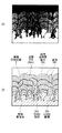
図1および図2は第1の二次電池の断面構成を表しており、図2では図1に示した巻回電極体20の一部を拡大して示している。この電池は、例えば、負極の容量が電極反応物質であるリチウムの吸蔵および放出に基づいて表されるリチウムイオン二次電池である。
(First secondary battery)
1 and 2 show a cross-sectional configuration of the first secondary battery, and FIG. 2 shows an enlarged part of the spirally
この二次電池は、主に、ほぼ中空円柱状の電池缶11の内部に、セパレータ23を介して正極21と負極22とが巻回された巻回電極体20と、一対の絶縁板12,13とが収納されたものである。この円柱状の電池缶11を用いた電池構造は、円筒型と呼ばれている。
The secondary battery mainly includes a
電池缶11は、例えば、一端部が閉鎖されると共に他端部が開放された中空構造を有しており、鉄、アルミニウムあるいはそれらの合金などの金属材料によって構成されている。なお、電池缶11が鉄によって構成される場合には、例えば、ニッケルなどの鍍金が施されてもよい。一対の絶縁板12,13は、巻回電極体20を上下から挟み、その巻回周面に対して垂直に延在するように配置されている。
The battery can 11 has, for example, a hollow structure in which one end is closed and the other end is opened, and is made of a metal material such as iron, aluminum, or an alloy thereof. In addition, when the battery can 11 is comprised with iron, plating, such as nickel, may be given, for example. The pair of insulating plates 12 and 13 are arranged so as to sandwich the
電池缶11の開放端部には、電池蓋14と、その内側に設けられた安全弁機構15および熱感抵抗素子(Positive Temperature Coefficient;PTC素子)16とが、ガスケット17を介してかしめて取り付けられており、電池缶11の内部は密閉されている。電池蓋14は、例えば、電池缶11と同様の金属材料によって構成されている。安全弁機構15は、熱感抵抗素子16を介して電池蓋14と電気的に接続されている。この安全弁機構15では、内部短絡あるいは外部からの加熱などに起因して内圧が一定以上になると、ディスク板15Aが反転して電池蓋14と巻回電極体20との間の電気的接続が切断されるようになっている。熱感抵抗素子16は、温度の上昇に応じた抵抗の増大によって電流を制限し、大電流に起因する異常な発熱を防止するものである。ガスケット17は、例えば、絶縁材料によって構成されており、その表面にはアスファルトが塗布されている。
A
巻回電極体20の中心には、センターピン24が挿入されていてもよい。この巻回電極体20では、アルミニウムなどの金属材料によって構成された正極リード25が正極21に接続されていると共に、ニッケルなどの金属材料によって構成された負極リード26が負極22に接続されている。正極リード25は、安全弁機構15に溶接されて電池蓋14と電気的に接続されており、負極リード26は、電池缶11に溶接されて電気的に接続されている。
A center pin 24 may be inserted in the center of the
正極21は、例えば、対向する一対の面を有する正極集電体21Aの両面に正極活物質層21Bが設けられたものである。ただし、正極活物質層21Bは、正極集電体21Aの片面だけに設けられていてもよい。
The
正極集電体21Aは、例えば、アルミニウム、ニッケルあるいはステンレスなどの金属材料によって構成されている。
The positive electrode
正極活物質層21Bは、正極活物質として、リチウムを吸蔵および放出することが可能な正極材料のいずれか1種あるいは2種以上を含んでおり、必要に応じて、結着剤や導電剤などの他の材料を含んでいてもよい。
The positive electrode
リチウムを吸蔵および放出することが可能な正極材料としては、例えば、リチウム含有化合物が好ましい。高いエネルギー密度が得られるからである。このリチウム含有化合物としては、例えば、リチウムと遷移金属元素とを含む複合酸化物や、リチウムと遷移金属元素とを含むリン酸化合物などが挙げられる。中でも、遷移金属元素としてコバルト、ニッケル、マンガンおよび鉄からなる群のうちの少なくとも1種を含むものが好ましい。より高い電圧が得られるからである。その化学式は、例えば、Lix M1O2 あるいはLiy M2PO4 で表される。式中、M1およびM2は、1種類以上の遷移金属元素を表す。xおよびyの値は、充放電状態によって異なり、通常、0.05≦x≦1.10、0.05≦y≦1.10である。 As a positive electrode material capable of inserting and extracting lithium, for example, a lithium-containing compound is preferable. This is because a high energy density can be obtained. Examples of the lithium-containing compound include a composite oxide containing lithium and a transition metal element, and a phosphate compound containing lithium and a transition metal element. Especially, what contains at least 1 sort (s) of the group which consists of cobalt, nickel, manganese, and iron as a transition metal element is preferable. This is because a higher voltage can be obtained. The chemical formula is represented by, for example, Li x M1O 2 or Li y M2PO 4 . In the formula, M1 and M2 represent one or more transition metal elements. The values of x and y vary depending on the charge / discharge state, and are generally 0.05 ≦ x ≦ 1.10 and 0.05 ≦ y ≦ 1.10.
リチウムと遷移金属元素とを含む複合酸化物としては、例えば、リチウムコバルト複合酸化物(Lix CoO2 )、リチウムニッケル複合酸化物(Lix NiO2 )、リチウムニッケルコバルト複合酸化物(Lix Ni1-z Coz O2 (z<1))、リチウムニッケルコバルトマンガン複合酸化物(Lix Ni(1-v-w) Cov Mnw O2 (v+w<1))、またはスピネル型構造を有するリチウムマンガン複合酸化物(LiMn2 O4 )あるいはリチウムマンガンニッケル複合酸化物(LiMn2-t Nit O4 (t<2))などが挙げられる。中でも、コバルトを含む複合酸化物が好ましい。高い容量が得られると共に、優れたサイクル特性も得られるからである。また、リチウムと遷移金属元素とを含むリン酸化合物としては、例えば、リチウム鉄リン酸化合物(LiFePO4 )あるいはリチウム鉄マンガンリン酸化合物(LiFe1-u Mnu PO4 (u<1))などが挙げられる。 Examples of the composite oxide containing lithium and a transition metal element include lithium cobalt composite oxide (Li x CoO 2 ), lithium nickel composite oxide (Li x NiO 2 ), and lithium nickel cobalt composite oxide (Li x Ni). 1-z Co z O 2 (z <1)), lithium nickel cobalt manganese composite oxide (Li x Ni (1-vw) Co v Mn w O 2 (v + w <1)), or lithium having a spinel structure Examples thereof include manganese composite oxide (LiMn 2 O 4 ) and lithium manganese nickel composite oxide (LiMn 2−t N t O 4 (t <2)). Among these, a complex oxide containing cobalt is preferable. This is because a high capacity can be obtained and excellent cycle characteristics can be obtained. Examples of the phosphate compound containing lithium and a transition metal element include a lithium iron phosphate compound (LiFePO 4 ) or a lithium iron manganese phosphate compound (LiFe 1-u Mn u PO 4 (u <1)). Is mentioned.
この他、リチウムを吸蔵および放出することが可能な正極材料としては、例えば、酸化チタン、酸化バナジウムあるいは二酸化マンガンなどの酸化物や、二硫化チタンあるいは硫化モリブデンなどの二硫化物や、セレン化ニオブなどのカルコゲン化物や、硫黄、ポリアニリンあるいはポリチオフェンなどの導電性高分子も挙げられる。 In addition, examples of the positive electrode material capable of inserting and extracting lithium include oxides such as titanium oxide, vanadium oxide and manganese dioxide, disulfides such as titanium disulfide and molybdenum sulfide, and niobium selenide. And chalcogenides such as sulfur, polyaniline and polythiophene, and other conductive polymers.
もちろん、リチウムを吸蔵および放出することが可能な正極材料は、上記以外のものであってもよい。また、上記した一連の正極材料は、任意の組み合わせで2種以上混合されてもよい。 Of course, the positive electrode material capable of inserting and extracting lithium may be other than the above. Further, two or more kinds of the series of positive electrode materials described above may be mixed in any combination.
導電剤としては、例えば、黒鉛、カーボンブラック、アセチレンブラックあるいはケチェンブラックなどの炭素材料が挙げられる。これらは単独でもよいし、複数種が混合されてもよい。なお、導電剤は、導電性を有する材料であれば、金属材料あるいは導電性高分子などであってもよい。 Examples of the conductive agent include carbon materials such as graphite, carbon black, acetylene black, and ketjen black. These may be single and multiple types may be mixed. Note that the conductive agent may be a metal material or a conductive polymer as long as it is a conductive material.
結着剤としては、例えば、スチレンブタジエン系ゴム、フッ素系ゴムあるいはエチレンプロピレンジエンなどの合成ゴムや、ポリフッ化ビニリデンなどの高分子材料が挙げられる。これらは単独でもよいし、複数種が混合されてもよい。 Examples of the binder include synthetic rubbers such as styrene butadiene rubber, fluorine rubber or ethylene propylene diene, and polymer materials such as polyvinylidene fluoride. These may be single and multiple types may be mixed.
負極22は、例えば、一対の面を有する負極集電体22Aの両面に負極活物質層22Bが設けられたものである。ただし、負極活物質層22Bは、負極集電体22Aの片面だけに設けられていてもよい。
In the
負極集電体22Aは、例えば、銅、ニッケルあるいはステンレスなどの金属材料によって構成されている。この負極集電体22Aの表面は、粗面化されているのが好ましい。いわゆるアンカー効果によって負極集電体22Aと負極活物質層22Bとの間の密着性が向上するからである。この場合には、少なくとも負極活物質層22Bと対向する領域において、負極集電体22Aの表面が粗面化されていればよい。粗面化の方法としては、例えば、電解処理によって微粒子を形成する方法などが挙げられる。この電解処理とは、電解槽中において電解法によって負極集電体22Aの表面に微粒子を形成して凹凸を設ける方法である。この電解処理によって粗面化された銅箔を含め、電解法によって作製された銅箔は、一般に「電解銅箔」と呼ばれている。
The anode
負極活物質層22Bは、負極活物質として、リチウムを吸蔵および放出することが可能な負極材料のいずれか1種あるいは2種以上を含んでおり、必要に応じて、結着剤や導電剤などの他の材料を含んでいてもよい。なお、結着剤および導電剤に関する詳細は、例えば、正極21について説明した場合と同様である。また、リチウムを吸蔵および放出することが可能な負極材料の充電容量は、正極活物質による充電容量よりも大きくなっているのが好ましい。満充電時においても、負極22にリチウムがデンドライトとなって析出する可能性が低くなるからである。
The negative electrode active material layer 22B includes one or more negative electrode materials capable of inserting and extracting lithium as a negative electrode active material, and a binder, a conductive agent, and the like as necessary. Other materials may be included. Note that details regarding the binder and the conductive agent are the same as those described for the
リチウムを吸蔵および放出することが可能な負極材料としては、例えば、リチウムを吸蔵および放出することが可能であると共に金属元素および半金属元素のうちの少なくとも1種を構成元素として有する材料が挙げられる。高いエネルギー密度が得られるからである。このような負極材料は、金属元素あるいは半金属元素の単体でも合金でも化合物でもよく、それらの1種あるいは2種以上の相を少なくとも一部に有するようなものでもよい。なお、ここで言う「合金」には、2種以上の金属元素からなるものに加えて、1種以上の金属元素と1種以上の半金属元素とを含むものも含まれる。また、「合金」は、非金属元素を含んでいてもよい。この組織には、固溶体、共晶(共融混合物)、金属間化合物、あるいはそれらの2種以上が共存するものがある。 Examples of the negative electrode material capable of inserting and extracting lithium include materials capable of inserting and extracting lithium and having at least one of a metal element and a metalloid element as a constituent element. . This is because a high energy density can be obtained. Such a negative electrode material may be a single element or an alloy or a compound of a metal element or a metalloid element, and may have one or two or more phases thereof at least in part. In addition, the “alloy” mentioned here includes an alloy containing one or more metal elements and one or more metalloid elements in addition to an alloy composed of two or more metal elements. Further, the “alloy” may contain a nonmetallic element. This structure includes a solid solution, a eutectic (eutectic mixture), an intermetallic compound, or a material in which two or more of them coexist.
上記した金属元素あるいは半金属元素としては、例えば、リチウムと合金を形成することが可能な金属元素あるいは半金属元素が挙げられる。具体的には、マグネシウム(Mg)、ホウ素(B)、アルミニウム、ガリウム(Ga)、インジウム(In)、ケイ素(Si)、ゲルマニウム(Ge)、スズ(Sn)、鉛(Pb)、ビスマス(Bi)、カドミウム(Cd)、銀(Ag)、亜鉛(Zn)、ハフニウム(Hf)、ジルコニウム(Zr)、イットリウム(Y)、パラジウム(Pd)あるいは白金(Pt)などである。これらの金属元素および半金属元素のうちの少なくとも1種を構成元素として有する材料としては、例えば、これらの金属元素あるいは半金族元素の合金または化合物が挙げられ、具体的には、Mas Mbt Liu (s、tおよびuの値はそれぞれs>0、t≧0、u≧0である。)や、Maq Mcq Mdr (p、qおよびrの値はそれぞれp>0、q>0、r≧0である。)の化学式で表されるものなどが挙げられる。ただし、Maはリチウムと合金を形成可能な金属元素および半金属元素のうちの少なくとも1種を表し、MbはリチウムおよびMa以外の金属元素および半金属元素のうちの少なくとも1種を表わしている。また、Mcは非金属元素のうちの少なくとも1種を表し、MdはMa以外の金属元素および半金属元素のうちの少なくとも1種を表している。これらの材料は結晶質であってもよく、非晶質(アモルファス)であってもよい。 Examples of the metal element or metalloid element described above include a metal element or metalloid element capable of forming an alloy with lithium. Specifically, magnesium (Mg), boron (B), aluminum, gallium (Ga), indium (In), silicon (Si), germanium (Ge), tin (Sn), lead (Pb), bismuth (Bi) ), Cadmium (Cd), silver (Ag), zinc (Zn), hafnium (Hf), zirconium (Zr), yttrium (Y), palladium (Pd) or platinum (Pt). Examples of the material having at least one of these metal elements and metalloid elements as constituent elements include alloys or compounds of these metal elements or metalloid elements. Specifically, Ma s Mb t Li u (values of s, t and u are s> 0, t ≧ 0, u ≧ 0, respectively) and Ma q Mc q Md r (values of p, q and r are p> 0, respectively) q> 0, r ≧ 0)). However, Ma represents at least one of a metal element and a metalloid element capable of forming an alloy with lithium, and Mb represents at least one of a metal element and a metalloid element other than lithium and Ma. Mc represents at least one of non-metallic elements, and Md represents at least one of metallic elements and metalloid elements other than Ma. These materials may be crystalline or amorphous.
リチウムと合金を形成することが可能な金属元素あるいは半金属元素により構成された負極材料としては、長周期型周期表における14族の金属元素および半金族元素のうちの少なくとも1種を構成元素として有する材料が好ましく、ケイ素およびスズのうちの少なくとも1種を構成元素として有する材料が特に好ましい。リチウムを吸蔵および放出する能力が大きいため、高いエネルギー密度が得られるからである。
As a negative electrode material composed of a metal element or a metalloid element capable of forming an alloy with lithium, at least one of a
ケイ素およびスズのうちの少なくとも1種を有する負極材料としては、例えば、ケイ素の単体、合金あるいは化合物や、スズの単体、合金あるいは化合物や、それらの1種あるいは2種以上の相を少なくとも一部に有する材料が挙げられる。 Examples of the negative electrode material having at least one of silicon and tin include at least a part of a simple substance, an alloy or a compound of silicon, a simple substance, an alloy or a compound of tin, or one or two or more phases thereof. The material which has in is mentioned.
ケイ素の合金としては、例えば、ケイ素以外の第2の構成元素として、スズ、ニッケル、銅、鉄、コバルト、マンガン、亜鉛、インジウム、銀、チタン、ゲルマニウム、ビスマス、アンチモン(Sb)およびクロムからなる群のうちの少なくとも1種を有するものが挙げられる。ケイ素の化合物としては、例えば、酸素あるいは炭素(C)を有するものが挙げられ、ケイ素に加えて、上記した第2の構成元素を有していてもよい。ケイ素の合金あるいは化合物の一例としては、SiB4 、SiB6 、Mg2 Si、Ni2 Si、TiSi2 、MoSi2 、CoSi2 、NiSi2 、CaSi2 、CrSi2 、Cu5 Si、FeSi2 、MnSi2 、NbSi2 、TaSi2 、VSi2 、WSi2 、ZnSi2 、SiC、Si3 N4 、Si2 N2 O、SiOv (0<v≦2)あるいはLiSiOなどが挙げられる。 Examples of the silicon alloy include, as the second constituent element other than silicon, tin, nickel, copper, iron, cobalt, manganese, zinc, indium, silver, titanium, germanium, bismuth, antimony (Sb), and chromium. Those having at least one of the groups are mentioned. Examples of the silicon compound include those having oxygen or carbon (C), and may contain the second constituent element described above in addition to silicon. Examples of silicon alloys or compounds include SiB 4 , SiB 6 , Mg 2 Si, Ni 2 Si, TiSi 2 , MoSi 2 , CoSi 2 , NiSi 2 , CaSi 2 , CrSi 2 , Cu 5 Si, FeSi 2 , MnSi. 2 , NbSi 2 , TaSi 2 , VSi 2 , WSi 2 , ZnSi 2 , SiC, Si 3 N 4 , Si 2 N 2 O, SiO v (0 <v ≦ 2) or LiSiO.
スズの合金としては、例えば、スズ以外の第2の構成元素として、ケイ素、ニッケル、銅、鉄、コバルト、マンガン、亜鉛、インジウム、銀、チタン、ゲルマニウム、ビスマス、アンチモンおよびクロムからなる群のうちの少なくとも1種を有するものが挙げられる。スズの化合物としては、例えば、酸素あるいは炭素を有するものが挙げられ、スズに加えて、上記した第2の構成元素を有していてもよい。スズの合金あるいは化合物の一例としては、SnOw (0<w≦2)、SnSiO3 、LiSnOあるいはMg2 Snなどが挙げられる。 As an alloy of tin, for example, as a second constituent element other than tin, among the group consisting of silicon, nickel, copper, iron, cobalt, manganese, zinc, indium, silver, titanium, germanium, bismuth, antimony and chromium The thing which has at least 1 sort (s) of these is mentioned. Examples of the tin compound include those having oxygen or carbon, and may contain the above-described second constituent element in addition to tin. Examples of tin alloys or compounds include SnO w (0 <w ≦ 2), SnSiO 3 , LiSnO, Mg 2 Sn, and the like.
特に、ケイ素およびスズのうちの少なくとも1種を有する負極材料としては、例えば、スズを第1の構成元素とし、それに加えて第2および第3の構成元素を有するものが好ましい。第2の構成元素は、コバルト、鉄、マグネシウム、チタン、バナジウム(V)、クロム、マンガン、ニッケル、銅、亜鉛、ガリウム、ジルコニウム、ニオブ(Nb)、モリブデン、銀、インジウム、セリウム(Ce)、ハフニウム、タンタル(Ta)、タングステン(W)、ビスマスおよびケイ素からなる群のうちの少なくとも1種である。第3の構成元素は、ホウ素、炭素、アルミニウムおよびリン(P)からなる群のうちの少なくとも1種である。第2および第3の構成元素を有することにより、サイクル特性が向上するからである。 In particular, as the negative electrode material having at least one of silicon and tin, for example, a material having tin and the second constituent element in addition to tin as the first constituent element is preferable. The second constituent elements are cobalt, iron, magnesium, titanium, vanadium (V), chromium, manganese, nickel, copper, zinc, gallium, zirconium, niobium (Nb), molybdenum, silver, indium, cerium (Ce), It is at least one selected from the group consisting of hafnium, tantalum (Ta), tungsten (W), bismuth and silicon. The third constituent element is at least one selected from the group consisting of boron, carbon, aluminum, and phosphorus (P). This is because having the second and third constituent elements improves the cycle characteristics.
中でも、スズ、コバルトおよび炭素を構成元素として有し、炭素の含有量が9.9質量%以上29.7質量%以下、スズおよびコバルトの合計に対するコバルトの割合(Co/(Sn+Co))が30質量%以上70質量%以下であるSnCoC含有材料が好ましい。このような組成範囲において、高いエネルギー密度が得られるからである。 Among them, tin, cobalt and carbon are included as constituent elements, the carbon content is 9.9 mass% or more and 29.7 mass% or less, and the ratio of cobalt to the total of tin and cobalt (Co / (Sn + Co)) is 30. An SnCoC-containing material having a mass% of 70% by mass or less is preferable. This is because a high energy density can be obtained in such a composition range.
このSnCoC含有材料は、必要に応じて、さらに他の構成元素を有していてもよい。他の構成元素としては、例えば、ケイ素、鉄、ニッケル、クロム、インジウム、ニオブ、ゲルマニウム、チタン、モリブデン、アルミニウム、リン、ガリウムあるいはビスマスなどが好ましく、それらの2種以上を有していてもよい。より高い効果が得られるからである。 This SnCoC-containing material may further contain other constituent elements as necessary. As other constituent elements, for example, silicon, iron, nickel, chromium, indium, niobium, germanium, titanium, molybdenum, aluminum, phosphorus, gallium, bismuth, and the like are preferable, and two or more of them may be included. . This is because a higher effect can be obtained.
なお、SnCoC含有材料は、スズ、コバルトおよび炭素を含む相を有しており、その相は、低結晶性あるいは非晶質な相であるのが好ましい。この相は、リチウムと反応可能な反応相であり、これによって優れたサイクル特性が得られるようになっている。この相のX線回折によって得られる回折ピークの半値幅は、特定X線としてCuKα線を用い、挿引速度を1°/minとした場合に、回折角2θで1.0°以上であることが好ましい。リチウムがより円滑に吸蔵および放出されると共に、電解質との反応性が低減されるからである。 The SnCoC-containing material has a phase containing tin, cobalt, and carbon, and the phase is preferably a low crystalline or amorphous phase. This phase is a reaction phase capable of reacting with lithium, whereby excellent cycle characteristics can be obtained. The half-value width of the diffraction peak obtained by X-ray diffraction of this phase is 1.0 ° or more at a diffraction angle 2θ when CuKα ray is used as the specific X-ray and the drawing speed is 1 ° / min. Is preferred. This is because lithium is occluded and released more smoothly and the reactivity with the electrolyte is reduced.
X線回折によって得られた回折ピークがリチウムと反応可能な反応相に対応するものであるか否かは、リチウムとの電気化学的反応の前後におけるX線回折チャートを比較することによって容易に判断することができる。例えば、リチウムとの電気化学的反応の前後において回折ピークの位置が変化すれば、リチウムと反応可能な反応相に対応するものである。この場合には、例えば、低結晶性あるいは非晶質な反応相の回折ピークが2θ=20°〜50°の間に見られる。この低結晶性あるいは非晶質な反応相は、例えば、上記した各構成元素を含んでおり、主に、炭素によって低結晶化あるいは非晶質化しているものと考えられる。 Whether or not the diffraction peak obtained by X-ray diffraction corresponds to a reaction phase capable of reacting with lithium can be easily determined by comparing X-ray diffraction charts before and after electrochemical reaction with lithium. can do. For example, if the position of the diffraction peak changes before and after the electrochemical reaction with lithium, it corresponds to a reaction phase capable of reacting with lithium. In this case, for example, a diffraction peak of a low crystalline or amorphous reaction phase is observed between 2θ = 20 ° and 50 °. This low crystalline or amorphous reaction phase contains, for example, each of the above-described constituent elements, and is considered to be mainly low-crystallized or amorphous due to carbon.
なお、SnCoC含有材料は、低結晶性あるいは非晶質な相に加えて、各構成元素の単体または一部を含む相を有している場合もある。 Note that the SnCoC-containing material may have a phase containing a simple substance or a part of each constituent element in addition to a low crystalline or amorphous phase.
特に、SnCoC含有材料では、構成元素である炭素の少なくとも一部が、他の構成元素である金属元素あるいは半金属元素と結合しているのが好ましい。スズなどの凝集あるいは結晶化が抑制されるからである。 In particular, in the SnCoC-containing material, it is preferable that at least a part of carbon as a constituent element is bonded to a metal element or a metalloid element as another constituent element. This is because aggregation or crystallization of tin or the like is suppressed.
元素の結合状態を調べる測定方法としては、例えばX線光電子分光法(X-ray Photoelectron Spectroscopy;XPS)が挙げられる。このXPSは、軟X線(市販の装置ではAl−Kα線か、Mg−Kα線を用いる)を試料表面に照射し、試料表面から飛び出してくる光電子の運動エネルギーを測定することによって、試料表面から数nmの領域の元素組成、および元素の結合状態を調べる方法である。 As a measuring method for examining the bonding state of elements, for example, X-ray photoelectron spectroscopy (XPS) can be cited. This XPS irradiates the sample surface with soft X-rays (Al-Kα ray or Mg-Kα ray is used in a commercial apparatus), and measures the kinetic energy of photoelectrons jumping out of the sample surface. To elemental composition in the region of several nanometers and the bonding state of the elements.
元素の内殻軌道電子の束縛エネルギーは、第1近似的には、元素上の電荷密度と相関して変化する。例えば、炭素元素の電荷密度が近傍に存在する元素との相互作用によって減少した場合には、2p電子などの外殻電子が減少しているので、炭素元素の1s電子は殻から強い束縛力を受けることになる。すなわち、元素の電荷密度が減少すると、束縛エネルギーは高くなる。XPSでは、束縛エネルギーが高くなると、高いエネルギー領域にピークはシフトするようになっている。 The binding energy of the core orbital electrons of the element changes in a first approximation in correlation with the charge density on the element. For example, when the charge density of the carbon element decreases due to an interaction with an element present in the vicinity, the outer electrons such as 2p electrons decrease, so the 1s electron of the carbon element exerts a strong binding force from the shell. Will receive. That is, the binding energy increases as the charge density of the element decreases. In XPS, when the binding energy increases, the peak shifts to a high energy region.
XPSにおいて、炭素の1s軌道(C1s)のピークは、グラファイトであれば、金原子の4f軌道(Au4f)のピークが84.0eVに得られるようにエネルギー較正された装置において、284.5eVに現れる。また、表面汚染炭素であれば、284.8eVに現れる。これに対して、炭素元素の電荷密度が高くなる場合、例えば炭素よりも陽性な元素と結合している場合には、C1sのピークは、284.5eVよりも低い領域に現れる。すなわち、SnCoC含有材料に含まれる炭素の少なくとも一部が他の構成元素である金属元素または半金属元素などと結合している場合には、SnCoC含有材料について得られるC1sの合成波のピークが284.5eVよりも低い領域に現れる。 In XPS, if the peak of carbon 1s orbital (C1s) is graphite, it appears at 284.5 eV in an energy calibrated apparatus so that the peak of 4f orbital (Au4f) of gold atom is obtained at 84.0 eV. . Moreover, if it is surface contamination carbon, it will appear at 284.8 eV. On the other hand, when the charge density of the carbon element is high, for example, when it is bonded to an element more positive than carbon, the C1s peak appears in a region lower than 284.5 eV. That is, when at least a part of the carbon contained in the SnCoC-containing material is bonded to another constituent element such as a metal element or a metalloid element, the peak of the synthetic wave of C1s obtained for the SnCoC-containing material is 284. Appears in the region lower than 5 eV.
なお、XPS測定を行う場合には、表面が表面汚染炭素で覆われている際に、XPS装置に付属のアルゴンイオン銃で表面を軽くスパッタするのが好ましい。また、測定対象のSnCoC含有材料が負極22中に存在する場合には、二次電池を解体して負極22を取り出したのち、炭酸ジメチルなどの揮発性溶媒で洗浄するとよい。負極22の表面に存在する揮発性の低い溶媒と電解質塩とを除去するためである。これらのサンプリングは、不活性雰囲気下で行うのが望ましい。
When performing XPS measurement, it is preferable that the surface is lightly sputtered with an argon ion gun attached to the XPS apparatus when the surface is covered with surface-contaminated carbon. When the SnCoC-containing material to be measured is present in the
また、XPS測定では、スペクトルのエネルギー軸の補正に、例えばC1sのピークを用いる。通常、物質表面には表面汚染炭素が存在しているので、表面汚染炭素のC1sのピークを284.8eVとし、それをエネルギー基準とする。なお、XPS測定では、C1sのピークの波形は、表面汚染炭素のピークとSnCoC含有材料中の炭素のピークとを含んだ形として得られるので、例えば市販のソフトウエアを用いて解析することにより、表面汚染炭素のピークと、SnCoC含有材料中の炭素のピークとを分離する。波形の解析では、最低束縛エネルギー側に存在する主ピークの位置をエネルギー基準(284.8eV)とする。 In XPS measurement, for example, the peak of C1s is used to correct the energy axis of the spectrum. Usually, since surface-contaminated carbon exists on the surface of the substance, the C1s peak of the surface-contaminated carbon is set to 284.8 eV, which is used as an energy standard. In XPS measurement, the waveform of the peak of C1s is obtained as a form including the surface contamination carbon peak and the carbon peak in the SnCoC-containing material. For example, by analyzing using commercially available software, The surface contamination carbon peak is separated from the carbon peak in the SnCoC-containing material. In the waveform analysis, the position of the main peak existing on the lowest bound energy side is used as the energy reference (284.8 eV).
このSnCoC含有材料は、例えば、各構成元素の原料を混合した混合物を電気炉、高周波誘導炉あるいはアーク溶解炉などで溶解させたのち、凝固させることによって形成可能である。また、ガスアトマイズあるいは水アトマイズなどの各種アトマイズ法や、各種ロール法や、メカニカルアロイング法あるいはメカニカルミリング法などのメカノケミカル反応を利用した方法などを用いてもよい。中でも、メカノケミカル反応を利用した方法が好ましい。SnCoC含有材料が低結晶性あるいは非晶質な構造になるからである。メカノケミカル反応を利用した方法では、例えば、遊星ボールミル装置やアトライタなどの製造装置を用いることができる。 This SnCoC-containing material can be formed, for example, by melting a mixture of raw materials of each constituent element in an electric furnace, a high-frequency induction furnace, an arc melting furnace or the like and then solidifying the mixture. Also, various atomizing methods such as gas atomization or water atomization, methods using various mechanochemical reactions such as various roll methods, mechanical alloying methods, and mechanical milling methods may be used. Among these, a method using a mechanochemical reaction is preferable. This is because the SnCoC-containing material has a low crystalline or amorphous structure. In the method using the mechanochemical reaction, for example, a manufacturing apparatus such as a planetary ball mill apparatus or an attritor can be used.
原料には、各構成元素の単体を混合して用いてもよいが、炭素以外の構成元素の一部については合金を用いるのが好ましい。このような合金に炭素を加えてメカニカルアロイング法を利用した方法によって合成することにより、低結晶性あるいは非晶質な構造が得られ、反応時間も短縮されるからである。なお、原料の形態は、粉体であってもよいし、塊状であってもよい。 The raw material may be a mixture of individual constituent elements, but it is preferable to use an alloy for some of the constituent elements other than carbon. This is because, by adding carbon to such an alloy and synthesizing it by a method using a mechanical alloying method, a low crystalline or amorphous structure is obtained, and the reaction time is shortened. The raw material may be in the form of powder or a block.
このSnCoC含有材料の他、スズ、コバルト、鉄および炭素を構成元素として有するSnCoFeC含有材料も好ましい。このSnCoFeC含有材料の組成は、任意に設定可能である。例えば、鉄の含有量を少なめに設定する場合の組成としては、炭素の含有量が9.9質量%以上29.7質量%以下、鉄の含有量が0.3質量%以上5.9質量%以下、スズとコバルトとの合計に対するコバルトの割合(Co/(Sn+Co))が30質量%以上70質量%以下であるのが好ましい。また、例えば、鉄の含有量を多めに設定する場合の組成としては、炭素の含有量が11.9質量%以上29.7質量%以下、スズとコバルトと鉄との合計に対するコバルトと鉄との合計の割合((Co+Fe)/(Sn+Co+Fe))が26.4質量%以上48.5質量%以下、コバルトと鉄との合計に対するコバルトの割合(Co/(Co+Fe))が9.9質量%以上79.5質量%以下であるのが好ましい。このような組成範囲において、高いエネルギー密度が得られるからである。このSnCoFeC含有材料の結晶性、元素の結合状態の測定方法、および形成方法などについては、上記したSnCoC含有材料と同様である。 In addition to this SnCoC-containing material, an SnCoFeC-containing material having tin, cobalt, iron and carbon as constituent elements is also preferable. The composition of the SnCoFeC-containing material can be arbitrarily set. For example, as a composition when the iron content is set to be small, the carbon content is 9.9 mass% or more and 29.7 mass% or less, and the iron content is 0.3 mass% or more and 5.9 mass%. %, And the ratio of cobalt to the total of tin and cobalt (Co / (Sn + Co)) is preferably 30% by mass or more and 70% by mass or less. In addition, for example, as a composition when the content of iron is set to be large, the content of carbon is 11.9 mass% or more and 29.7 mass% or less, and cobalt and iron with respect to the total of tin, cobalt, and iron The total ratio of (Co + Fe) / (Sn + Co + Fe)) is 26.4 mass% to 48.5 mass%, and the ratio of cobalt to the total of cobalt and iron (Co / (Co + Fe)) is 9.9 mass% It is preferable that it is 79.5 mass% or more. This is because a high energy density can be obtained in such a composition range. The crystallinity of the SnCoFeC-containing material, the method for measuring the bonding state of elements, the formation method, and the like are the same as those of the above-described SnCoC-containing material.
リチウムを吸蔵および放出することが可能な負極材料として、ケイ素の単体、合金あるいは化合物や、スズの単体、合金あるいは化合物や、それらの1種あるいは2種以上の相を少なくとも一部に有する材料を用いた負極活物質層22Bは、例えば、気相法、液相法、溶射法、塗布法あるいは焼成法、またはそれらの2種以上の方法を用いて形成される。この場合には、負極集電体22Aと負極活物質層22Bとが界面の少なくとも一部において合金化しているのが好ましい。詳細には、両者の界面において、負極集電体22Aの構成元素が負極活物質層22Bに拡散していてもよいし、負極活物質層22Bの構成元素が負極集電体22Aに拡散していてもよいし、それらの構成元素が互いに拡散し合っていてもよい。充放電時における負極活物質層22Bの膨張および収縮に起因する破壊が抑制されると共に、負極集電体22Aと負極活物質層22Bとの間の電子伝導性が向上するからである。
As a negative electrode material capable of inserting and extracting lithium, a simple substance, an alloy or a compound of silicon, a simple substance, an alloy or a compound of tin, or a material having one or more phases thereof at least in part. The used negative electrode active material layer 22B is formed by using, for example, a gas phase method, a liquid phase method, a thermal spraying method, a coating method or a firing method, or two or more of these methods. In this case, it is preferable that the anode
なお、気相法としては、例えば、物理堆積法あるいは化学堆積法、具体的には真空蒸着法、スパッタ法、イオンプレーティング法、レーザーアブレーション法、熱化学気相成長(Chemical Vapor Deposition :CVD)法あるいはプラズマ化学気相成長法などが挙げられる。液相法としては、電解鍍金あるいは無電解鍍金などの公知の手法を用いることができる。塗布法とは、例えば、粒子状の負極活物質を結着剤などと混合したのち、溶剤に分散させて塗布する方法である。焼成法とは、例えば、塗布法によって塗布したのち、結着剤などの融点よりも高い温度で熱処理する方法である。焼成法に関しても公知の手法が利用可能であり、例えば、雰囲気焼成法、反応焼成法あるいはホットプレス焼成法が挙げられる。 As the vapor phase method, for example, physical deposition method or chemical deposition method, specifically, vacuum deposition method, sputtering method, ion plating method, laser ablation method, thermal chemical vapor deposition (CVD) Or plasma chemical vapor deposition. As the liquid phase method, a known method such as electrolytic plating or electroless plating can be used. The application method is, for example, a method in which a particulate negative electrode active material is mixed with a binder and then dispersed in a solvent and applied. The baking method is, for example, a method in which a heat treatment is performed at a temperature higher than the melting point of a binder or the like after being applied by a coating method. A known method can also be used for the firing method, for example, an atmospheric firing method, a reactive firing method, or a hot press firing method.
上記した他、リチウムを吸蔵および放出することが可能な負極材料としては、例えば、炭素材料が挙げられる。この炭素材料とは、例えば、易黒鉛化性炭素や、(002)面の面間隔が0.37nm以上の難黒鉛化性炭素や、(002)面の面間隔が0.34nm以下の黒鉛などである。より具体的には、熱分解炭素類、コークス類、ガラス状炭素繊維、有機高分子化合物焼成体、活性炭あるいはカーボンブラック類などがある。このうち、コークス類には、ピッチコークス、ニードルコークスあるいは石油コークスなどが含まれる。有機高分子化合物焼成体とは、フェノール樹脂やフラン樹脂などを適当な温度で焼成して炭素化したものをいう。炭素材料は、リチウムの吸蔵および放出に伴う結晶構造の変化が非常に少ないため、高いエネルギー密度が得られると共に優れたサイクル特性が得られ、さらに導電剤としても機能するので好ましい。なお、炭素材料の形状は、繊維状、球状、粒状あるいは鱗片状のいずれでもよい。 In addition to the above, examples of the anode material capable of inserting and extracting lithium include a carbon material. Examples of the carbon material include graphitizable carbon, non-graphitizable carbon having a (002) plane spacing of 0.37 nm or more, and graphite having a (002) plane spacing of 0.34 nm or less. It is. More specifically, there are pyrolytic carbons, cokes, glassy carbon fibers, organic polymer compound fired bodies, activated carbon or carbon blacks. Of these, the cokes include pitch coke, needle coke, petroleum coke, and the like. The organic polymer compound fired body is obtained by firing and carbonizing a phenol resin, a furan resin, or the like at an appropriate temperature. The carbon material is preferable because the change in crystal structure associated with insertion and extraction of lithium is very small, so that a high energy density can be obtained, and excellent cycle characteristics can be obtained. The shape of the carbon material may be any of fibrous, spherical, granular or scale-like.
また、リチウムを吸蔵および放出することが可能な負極材料としては、例えば、リチウムを吸蔵および放出することが可能な金属酸化物あるいは高分子化合物なども挙げられる。金属酸化物としては、例えば、酸化鉄、酸化ルテニウムあるいは酸化モリブデンなどが挙げられる。高分子化合物としては、例えば、ポリアセチレン、ポリアニリンあるいはポリピロールなどが挙げられる。 Further, examples of the negative electrode material capable of inserting and extracting lithium include metal oxides and polymer compounds capable of inserting and extracting lithium. Examples of the metal oxide include iron oxide, ruthenium oxide, and molybdenum oxide. Examples of the polymer compound include polyacetylene, polyaniline, and polypyrrole.
もちろん、リチウムを吸蔵および放出することが可能な負極材料は、上記以外のものであってもよい。また、上記した一連の負極材料は、任意の組み合わせで2種以上混合されもよい。 Of course, the negative electrode material capable of inserting and extracting lithium may be other than the above. Moreover, two or more kinds of the series of negative electrode materials described above may be mixed in any combination.
上記した負極材料からなる負極活物質は、複数の粒子状をなしている。すなわち、負極活物質層22Bは、複数の負極活物質粒子を有しており、その負極活物質粒子は、例えば、上記した気相法などによって形成されている。ただし、負極活物質粒子は、気相法以外の方法によって形成されていてもよい。 The negative electrode active material made of the negative electrode material described above has a plurality of particles. That is, the negative electrode active material layer 22B has a plurality of negative electrode active material particles, and the negative electrode active material particles are formed by, for example, the above-described vapor phase method. However, the negative electrode active material particles may be formed by a method other than the gas phase method.
負極活物質粒子が気相法などの堆積法によって形成される場合には、その負極活物質粒子が単一の堆積工程を経て形成された単層構造を有していてもよいし、複数回の堆積工程を経て形成された多層構造を有していてもよい。ただし、堆積時に高熱を伴う蒸着法などによって負極活物質粒子を形成する場合には、その負極活物質粒子が多層構造を有しているのが好ましい。負極材料の堆積工程を複数回に分割して行う(負極材料を順次薄く形成して堆積させる)ことにより、その堆積工程を1回で行う場合と比較して負極集電体22Aが高熱に晒される時間が短くなり、熱的ダメージを受けにくくなるからである。
When the negative electrode active material particles are formed by a deposition method such as a vapor phase method, the negative electrode active material particles may have a single layer structure formed through a single deposition step, or may be a plurality of times. It may have a multilayer structure formed through the deposition process. However, when the negative electrode active material particles are formed by a vapor deposition method that involves high heat during deposition, the negative electrode active material particles preferably have a multilayer structure. By performing the deposition process of the negative electrode material in a plurality of times (the negative electrode material is sequentially formed and deposited thinly), the negative electrode
この負極活物質粒子は、例えば、負極集電体22Aの表面から負極活物質層22Bの厚さ方向に成長しており、その根元において負極集電体22Aに連結されている。この場合には、負極活物質粒子が気相法によって形成されており、上記したように、負極集電体22Aとの界面の少なくとも一部において合金化しているのが好ましい。詳細には、両者の界面において、負極集電体22Aの構成元素が負極活物質粒子に拡散していてもよいし、負極活物質粒子の構成元素が負極集電体22Aに拡散していてもよいし、両者の構成元素が互いに拡散しあっていてもよい。
The negative electrode active material particles grow, for example, from the surface of the negative electrode
特に、負極活物質層22Bは、必要に応じて、負極活物質粒子の表面(電解液と接する領域)を被覆する酸化物含有膜を有しているのが好ましい。酸化物含有膜が電解液に対する保護膜として機能し、充放電を繰り返しても電解液の分解反応が抑制されるため、サイクル特性が向上するからである。この酸化物含有膜は、負極活物質粒子の表面のうちの一部を被覆していてもよいし、全部を被覆していてもよい。 In particular, the negative electrode active material layer 22B preferably has an oxide-containing film that covers the surface of the negative electrode active material particles (a region in contact with the electrolytic solution) as necessary. This is because the oxide-containing film functions as a protective film against the electrolytic solution, and even when charging and discharging are repeated, the decomposition reaction of the electrolytic solution is suppressed, so that the cycle characteristics are improved. This oxide-containing film may cover a part of the surface of the negative electrode active material particles, or may cover the whole.
この酸化物含有膜は、金属元素あるいは半金属元素の酸化物を含有している。この金属元素あるいは半金属元素の酸化物としては、例えば、アルミニウム、ケイ素、亜鉛、ゲルマニウムあるいはスズなどの酸化物が挙げられる。中でも、この酸化物含有膜は、ケイ素、ゲルマニウムおよびスズからなる群のうちの少なくとも1種の酸化物を含有しているのが好ましく、特にケイ素の酸化物を含有しているのが好ましい。負極活物質粒子の表面を全体に渡って容易に被覆しやすいと共に、優れた保護機能が得られるからである。もちろん、酸化物含有膜は、上記以外の他の酸化物を含有していてもよい。 This oxide-containing film contains an oxide of a metal element or a metalloid element. Examples of the metal element or metalloid oxide include oxides such as aluminum, silicon, zinc, germanium, and tin. Among these, this oxide-containing film preferably contains at least one oxide selected from the group consisting of silicon, germanium and tin, and particularly preferably contains an oxide of silicon. This is because the entire surface of the negative electrode active material particles can be easily covered and an excellent protective function can be obtained. Of course, the oxide-containing film may contain an oxide other than the above.
この酸化物含有膜は、例えば、気相法あるいは液相法などの1種あるいは2種以上の方法を用いて形成される。この場合の気相法としては、例えば、蒸着法、スパッタ法あるいはCVD法などが挙げられ、液相法としては、例えば、液相析出法、ゾルゲル法、ポリシラザン法、電析法、塗布法あるいはディップコーティング法などが挙げられる。中でも、液相法が好ましく、液相析出法がより好ましい。負極活物質粒子の表面を広い範囲に渡って容易に被覆しやすいからである。なお、液相析出法では、まず、金属元素あるいは半金族元素のフッ化物錯体と共にアニオン捕捉剤としてフッ化物イオンを配位しやすい溶存種を含む溶液中において、フッ化物錯体から生じるフッ化物イオンをアニオン捕捉剤に補足させることによって、負極活物質粒子の表面が被覆されるように金属元素あるいは半金族元素の酸化物を析出させる。こののち、水洗および乾燥させることにより、酸化物含有膜を形成する。 The oxide-containing film is formed using one or more methods such as a gas phase method or a liquid phase method. Examples of the vapor phase method in this case include a vapor deposition method, a sputtering method, or a CVD method. Examples of the liquid phase method include a liquid phase precipitation method, a sol-gel method, a polysilazane method, an electrodeposition method, a coating method, or a coating method. Examples include dip coating. Among these, the liquid phase method is preferable, and the liquid phase precipitation method is more preferable. This is because the surface of the negative electrode active material particles can be easily covered over a wide range. In the liquid phase deposition method, first, fluoride ions generated from a fluoride complex in a solution containing a fluoride complex of a metal element or a semi-metal group element and a dissolved species that easily coordinates fluoride ions as an anion scavenger. Is added to the anion scavenger to deposit an oxide of a metal element or a semimetal group element so that the surface of the negative electrode active material particles is coated. Thereafter, the oxide-containing film is formed by washing with water and drying.
また、負極活物質層22Bは、必要に応じて、負極活物質粒子の粒子間の隙間や粒子内の隙間に、電極反応物質と合金化しない金属材料を有しているのが好ましい。金属材料を介して複数の負極活物質粒子が結着されると共に、上記した隙間に金属材料が存在することで負極活物質層22Bの膨張および収縮が抑制されるため、サイクル特性が向上するからである。 In addition, the negative electrode active material layer 22B preferably includes a metal material that does not alloy with the electrode reactant in the gaps between the particles of the negative electrode active material particles or the gaps in the particles as necessary. Since a plurality of negative electrode active material particles are bound via a metal material, and the expansion and contraction of the negative electrode active material layer 22B are suppressed due to the presence of the metal material in the gap, the cycle characteristics are improved. It is.
この金属材料は、例えば、リチウムと合金化しない金属元素を構成元素として有している。このような金属元素としては、例えば、鉄、コバルト、ニッケル、亜鉛および銅からなる群のうちの少なくとも1種が挙げられ、中でも、コバルトが好ましい。上記した隙間に金属材料が容易に入り込みやすいと共に、優れた結着作用が得られるからである。もちろん、金属材料は、上記以外の他の金属元素を有していてもよい。ただし、ここで言う「金属材料」とは、単体に限らず、合金や金属化合物まで含む広い概念である。この金属材料は、例えば、気相法あるいは液相法によって形成されており、中でも電解鍍金法あるいは無電解鍍金法などの液相法が好ましく、電解鍍金法がより好ましい。上記した隙間に金属材料が入り込みやすくなると共に、その形成時間が短くて済むからである。 This metal material has, for example, a metal element that does not alloy with lithium as a constituent element. Examples of such a metal element include at least one selected from the group consisting of iron, cobalt, nickel, zinc, and copper, and among these, cobalt is preferable. This is because the metal material can easily enter the gap, and an excellent binding action can be obtained. Of course, the metal material may have a metal element other than the above. However, the “metal material” mentioned here is not limited to a simple substance, but is a broad concept that includes alloys and metal compounds. This metal material is formed by, for example, a gas phase method or a liquid phase method, and among them, a liquid phase method such as an electrolytic plating method or an electroless plating method is preferable, and an electrolytic plating method is more preferable. This is because the metal material can easily enter the gap and the formation time can be shortened.
なお、負極活物質層22Bは、上記した酸化物含有膜あるいは金属材料のいずれか一方だけを有していてもよいし、双方を有していてもよい。ただし、サイクル特性をより向上させるためには、双方を含んでいるのが好ましい。 Note that the negative electrode active material layer 22B may include only one of the oxide-containing film or the metal material described above, or may include both. However, in order to further improve the cycle characteristics, it is preferable to include both.
ここで、図3〜図6を参照して、負極22の詳細な構成について説明する。
Here, the detailed configuration of the
まず、負極活物質層22Bが複数の負極活物質粒子と共に酸化物含有膜を有する場合について説明する。図3は負極22の断面構造を模式的に表しており、図4は参考例の負極の断面構造を模式的に表している。図3および図4では、負極活物質粒子が単層構造を有している場合を示している。
First, the case where the negative electrode active material layer 22B has an oxide-containing film together with a plurality of negative electrode active material particles will be described. FIG. 3 schematically shows a cross-sectional structure of the
負極活物質層22Bが複数の負極活物質粒子と共に酸化物含有膜を有する場合の負極22では、図3に示したように、例えば、蒸着法などの気相法によって負極集電体22A上に負極材料が堆積されると、その負極集電体22A上に複数の負極活物質粒子221が形成される。この場合には、負極集電体22Aの表面が粗面化され、その表面に複数の突起部(例えば、電解処理により形成された微粒子)が存在すると、負極活物質粒子221が上記した突起部ごとに厚さ方向に成長するため、複数の負極活物質粒子221が負極集電体22A上において配列されると共に根元において負極集電体22Aの表面に連結される。こののち、例えば、液相析出法などの液相法によって負極活物質粒子221の表面に酸化物含有膜222が形成されると、その酸化物含有膜222は負極活物質粒子221の表面をほぼ全体に渡って被覆し、特に、負極活物質粒子221の頭頂部から根元に至る広い範囲を被覆する。この酸化物含有膜222による広範囲な被覆状態は、その酸化物含有膜222が液相法によって形成された場合に得られる特徴である。すなわち、液相法によって酸化物含有膜222を形成すると、その被覆作用が負極活物質粒子221の頭頂部だけでなく根元まで広く及ぶため、その根元まで酸化物含有膜222によって被覆される。
In the
これに対して、参考例の負極では、図4に示したように、例えば、気相法によって複数の負極活物質粒子221が形成されたのち、同様に気相法によって酸化物含有膜223が形成されると、その酸化物含有膜223は負極活物質粒子221の頭頂部だけを被覆する。この酸化物含有膜223による狭範囲な被覆状態は、その酸化物含有膜223が気相法によって形成された場合に得られる特徴である。すなわち、気相法によって酸化物含有膜223を形成すると、その被覆作用が負極活物質粒子221の頭頂部に及ぶものの根元まで及ばないため、その根元までは酸化物含有膜223によって被覆されない。 On the other hand, in the negative electrode of the reference example, as shown in FIG. 4, for example, after the plurality of negative electrode active material particles 221 are formed by the vapor phase method, the oxide-containing film 223 is similarly formed by the vapor phase method. When formed, the oxide-containing film 223 covers only the tops of the negative electrode active material particles 221. This narrow-range covering state by the oxide-containing film 223 is a characteristic obtained when the oxide-containing film 223 is formed by a vapor phase method. That is, when the oxide-containing film 223 is formed by a vapor phase method, the covering action does not reach the root of the negative electrode active material particles 221, but the base is not covered with the oxide-containing film 223.
なお、図3では、気相法によって負極活物質層22Bが形成される場合について説明したが、焼結法などによって負極活物質層22Bが形成される場合においても同様に、複数の負極活物質粒子の表面をほぼ全体に渡って被覆するように酸化物含有膜が形成される。 Note that although FIG. 3 illustrates the case where the negative electrode active material layer 22B is formed by a vapor phase method, a plurality of negative electrode active materials are similarly formed when the negative electrode active material layer 22B is formed by a sintering method or the like. An oxide-containing film is formed so as to cover the entire surface of the particles.
次に、負極活物質層22Bが複数の負極活物質粒子と共に電極反応物質と合金化しない金属材料を有する場合について説明する。図5は負極22の断面構造を拡大して表しており、(A)は走査型電子顕微鏡(scanning electron microscope:SEM)写真(二次電子像)、(B)は(A)に示したSEM像の模式絵である。図5では、複数の負極活物質粒子221が粒子内に多層構造を有している場合を示している。
Next, the case where the negative electrode active material layer 22B includes a metal material that does not alloy with the electrode reactant together with the plurality of negative electrode active material particles will be described. FIG. 5 shows an enlarged cross-sectional structure of the
負極活物質粒子221が多層構造を有する場合には、その複数の負極活物質粒子221の配列構造、多層構造および表面構造に起因して、負極活物質層22B中に複数の隙間224が生じている。この隙間224は、主に、発生原因に応じて分類された2種類の隙間224A,224Bを含んでいる。隙間224Aは、隣り合う負極活物質粒子221間に生じるものであり、隙間224Bは、負極活物質粒子221内の各階層間に生じるものである。 When the negative electrode active material particles 221 have a multilayer structure, a plurality of gaps 224 are generated in the negative electrode active material layer 22B due to the arrangement structure, multilayer structure, and surface structure of the plurality of negative electrode active material particles 221. Yes. The gap 224 mainly includes two types of gaps 224A and 224B classified according to the cause of occurrence. The gap 224 </ b> A is generated between adjacent negative electrode active material particles 221, and the gap 224 </ b> B is generated between layers in the negative electrode active material particles 221.
なお、負極活物質粒子221の露出面(最表面)には、空隙225が生じる場合がある。この空隙225は、負極活物質粒子221の表面にひげ状の微細な突起部(図示せず)が生じることに伴い、その突起部間に生じるものである。この空隙225は、負極活物質粒子221の露出面において、全体に渡って生じる場合もあれば、一部だけに生じる場合もある。ただし、上記したひげ状の突起部は、負極活物質粒子221の形成時ごとにその表面に生じるため、空隙225は、負極活物質粒子221の露出面だけでなく、各階層間にも生じる場合がある。 Note that a void 225 may be formed on the exposed surface (outermost surface) of the negative electrode active material particles 221. The void 225 is generated between the protrusions as a whisker-like fine protrusion (not shown) is formed on the surface of the negative electrode active material particle 221. The void 225 may be generated over the entire exposed surface of the negative electrode active material particles 221 or may be generated only in part. However, since the above-described whisker-like protrusions are generated on the surface every time the negative electrode active material particles 221 are formed, the void 225 is generated not only on the exposed surface of the negative electrode active material particles 221 but also between the layers. There is.
図6は負極22の他の断面構造を表しており、図5に対応している。負極活物質層22Bは、隙間224A,224Bに、電極反応物質と合金化しない金属材料226を有している。この場合には、隙間224A,224Bのうちのいずれか一方だけに金属材料226を有していてもよいが、双方に金属材料226を有しているのが好ましい。より高い効果が得られるからである。
FIG. 6 shows another cross-sectional structure of the
この金属材料226は、隣り合う負極活物質粒子221間の隙間224Aに入り込んでいる。詳細には、気相法などによって負極活物質粒子221が形成される場合には、上記したように、負極集電体22Aの表面に存在する突起部ごとに負極活物質粒子221が成長するため、隣り合う負極活物質粒子221間に隙間224Aが生じる。この隙間224Aは、負極活物質層22Bの結着性を低下させる原因となるため、その結着性を高めるために、上記した隙間224Aに金属材料226が充填されている。この場合には、隙間224Aの一部でも充填されていればよいが、その充填量が多いほど好ましい。負極活物質層22Bの結着性がより向上するからである。金属材料226の充填量は、20%以上が好ましく、40%以上がより好ましく、80%以上がさらに好ましい。
The metal material 226 enters the gap 224A between the adjacent negative electrode active material particles 221. Specifically, when the negative electrode active material particles 221 are formed by a vapor phase method or the like, as described above, the negative electrode active material particles 221 grow for each protrusion existing on the surface of the negative electrode
また、金属材料226は、負極活物質粒子221内の隙間224Bに入り込んでいる。詳細には、負極活物質粒子221が多層構造を有する場合には、各階層間に隙間224Bが生じる。この隙間224Bは、上記した隙間224Aと同様に、負極活物質層22Bの結着性を低下させる原因となるため、その結着性を高めるために、上記した隙間224Bに金属材料226が充填されている。この場合には、隙間224Bの一部でも充填されていればよいが、その充填量が多いほど好ましい。負極活物質層22Bの結着性がより向上するからである。 In addition, the metal material 226 enters the gap 224 </ b> B in the negative electrode active material particles 221. Specifically, when the negative electrode active material particles 221 have a multilayer structure, a gap 224B is generated between the layers. The gap 224B, like the gap 224A, causes a decrease in the binding property of the negative electrode active material layer 22B. Therefore, in order to increase the binding property, the gap 224B is filled with the metal material 226. ing. In this case, it is sufficient that a part of the gap 224B is filled, but a larger filling amount is preferable. This is because the binding property of the negative electrode active material layer 22B is further improved.
なお、負極活物質層22Bは、最上層の負極活物質粒子221の露出面に生じるひげ状の微細な突起部(図示せず)が二次電池の性能に悪影響を及ぼすことを抑えるために、空隙225に金属材料226を有していてもよい。詳細には、気相法などによって負極活物質粒子221が形成される場合には、その表面にひげ状の微細な突起部が生じるため、その突起部間に空隙225が生じる。この空隙225は、負極活物質粒子221の表面積の増加を招き、その表面に形成される不可逆性の被膜の量も増加させるため、電極反応(充放電反応)の進行度を低下させる原因となる可能性がある。したがって、電極反応の進行度の低下を抑えるために、上記した空隙225に金属材料226が埋め込まれている。この場合には、空隙225の一部でも埋め込まれていればよいが、その埋め込む量が多いほど好ましい。電極反応の進行度の低下がより抑えられるからである。図6において、最上層の負極活物質粒子221の表面に金属材料226が点在していることは、その点在箇所に上記した微細な突起部が存在していること表している。もちろん、金属材料226は、必ずしも負極活物質粒子221の表面に点在していなければならないわけではなく、その表面全体を被覆していてもよい。 Note that the negative electrode active material layer 22B is provided in order to prevent negative whisker-like protrusions (not shown) generated on the exposed surface of the uppermost negative electrode active material particles 221 from adversely affecting the performance of the secondary battery. A metal material 226 may be provided in the gap 225. Specifically, when the negative electrode active material particles 221 are formed by a vapor phase method or the like, fine whisker-like protrusions are formed on the surface thereof, and thus voids 225 are generated between the protrusions. This void 225 causes an increase in the surface area of the negative electrode active material particles 221 and also increases the amount of irreversible film formed on the surface, which causes a reduction in the degree of progress of the electrode reaction (charge / discharge reaction). there is a possibility. Therefore, the metal material 226 is embedded in the above-described gap 225 in order to suppress a decrease in the progress of the electrode reaction. In this case, it is sufficient that a part of the gap 225 is embedded, but it is preferable that the amount to be embedded is larger. This is because a decrease in the degree of progress of the electrode reaction is further suppressed. In FIG. 6, the fact that the metal material 226 is scattered on the surface of the uppermost negative electrode active material particle 221 indicates that the above-described fine protrusions are present at the spot. Of course, the metal material 226 does not necessarily have to be scattered on the surface of the negative electrode active material particle 221, and may cover the entire surface.
特に、隙間224Bに入り込んだ金属材料226は、各階層における空隙225を埋め込む機能も果たしている。詳細には、負極材料が複数回に渡って堆積される場合には、その堆積時ごとに負極活物質粒子221の表面に上記した微細な突起部が生じる。このことから、金属材料226は、各階層における隙間224Bに充填されているだけでなく、各階層における空隙225も埋め込んでいる。 In particular, the metal material 226 that has entered the gap 224B also functions to fill the gap 225 in each layer. Specifically, when the negative electrode material is deposited a plurality of times, the fine protrusions described above are generated on the surface of the negative electrode active material particles 221 every time the negative electrode material is deposited. From this, the metal material 226 not only fills the gap 224B in each layer, but also fills the gap 225 in each layer.
なお、図5および図6では、負極活物質粒子221が多層構造を有しており、負極活物質層22B中に隙間224A,224Bの双方が存在している場合について説明したため、負極活物質層22Bが隙間224A,224Bに金属材料226を有している。これに対して、負極活物質粒子221が単層構造を有しており、負極活物質層22B中に隙間224Aだけが存在する場合には、負極活物質層22Bが隙間224Aだけに金属材料226を有することとなる。もちろん、空隙225は両者の場合において生じるため、いずれの場合においても空隙225に金属材料226を有することとなる。 5 and 6, the negative electrode active material particles 221 have a multilayer structure, and the case where both the gaps 224A and 224B exist in the negative electrode active material layer 22B has been described. 22B has a metal material 226 in the gaps 224A and 224B. On the other hand, when the negative electrode active material particle 221 has a single layer structure and only the gap 224A exists in the negative electrode active material layer 22B, the negative electrode active material layer 22B has the metal material 226 only in the gap 224A. It will have. Of course, since the gap 225 is generated in both cases, the gap 225 has the metal material 226 in either case.
セパレータ23は、正極21と負極22とを隔離し、両極の接触に起因する電流の短絡(ショート)を防止しながらリチウムイオンを通過させるものである。このセパレータ23は、例えば、平均孔径が5μm程度あるいはそれ以下の多孔質膜であってもよく、具体的には、ポリテトラフルオロエチレン、ポリプロピレンあるいはポリエチレンなどの合成樹脂からなる多孔質膜、またはセラミックからなる多孔質膜や、これらの2種以上の多孔質膜が積層されたものなどが挙げられる。中でも、ポリオレフィン製の多孔質膜は、ショート防止効果に優れ、かつシャットダウン効果による二次電池の安全性向上を図ることができるので好ましい。特に、ポリエチレンは、100℃以上160℃以下でシャットダウン効果を得ることができると共に、電気化学的安定性が優れているので好ましい。また、ポリプロピレンも好ましく、他にも化学的安定性を備えた樹脂であれば、ポリエチレンあるいはポリプロピレンと共重合させたものや、ブレンド化したものであってもよい。
The
セパレータ23には、液状の電解質として上記した電解液が含浸されている。サイクル特性が向上するからである。
The
この二次電池は、例えば、以下の手順によって製造される。 This secondary battery is manufactured, for example, by the following procedure.
まず、正極21を作製する。最初に、正極活物質と、結着剤と、導電剤とを混合して正極合剤としたのち、有機溶剤に分散させてペースト状の正極合剤スラリーとする。続いて、ドクタブレードあるいはバーコータなどによって正極集電体21Aの両面に正極合剤スラリーを均一に塗布して乾燥させる。最後に、必要に応じて加熱しながらロールプレス機などによって塗膜を圧縮成型して正極活物質層21Bを形成する。この場合には、圧縮成型を複数回に渡って繰り返してもよい。
First, the
次に、負極22を作製する。最初に、電解銅箔などからなる負極集電体22Aを準備したのち、蒸着法などの気相法によって負極集電体22Aの両面に負極材料を堆積させて、複数の負極活物質粒子を形成する。最後に、必要に応じて、液相析出法などの液相法によって酸化物含有膜を形成し、あるいは電解鍍金法などの液相法によって金属材料を形成して、負極活物質層22Bを形成する。
Next, the
次に、正極集電体21Aに正極リード25を溶接などして取り付けると共に、負極集電体22Aに負極リード26を溶接などして取り付けたのち、セパレータ23を介して正極21と負極22とを積層させてから、長手方向において巻回させて巻回電極体20を作製する。
Next, the
二次電池の組み立ては、以下のようにして行う。最初に、巻回電極体20の巻回中心部にセンターピン24を挿入する。続いて、巻回電極体20を一対の絶縁板12,13で挟みながら電池缶11の内部に収納すると共に、正極リード25の先端部を安全弁機構15に溶接し、負極リード26の先端部を電池缶11に溶接する。続いて、電池缶11の内部に電解液を注入してセパレータ23に含浸させる。最後に、電池缶11の開口端部に電池蓋14、安全弁機構15および熱感抵抗素子16をガスケット17を介してかしめることにより固定する。これにより、図1および図2に示した二次電池が完成する。
The secondary battery is assembled as follows. First, the center pin 24 is inserted into the winding center portion of the winding
この二次電池では、充電を行うと、例えば、正極21からリチウムイオンが放出され、セパレータ23に含浸された電解液を介して負極22に吸蔵される。一方、放電を行うと、例えば、負極22からリチウムイオンが放出され、セパレータ23に含浸された電解液を介して正極21に吸蔵される。
In the secondary battery, when charged, for example, lithium ions are extracted from the
この円筒型の二次電池によれば、負極22の容量がリチウムの吸蔵および放出に基づいて表される場合に、上記した電解液を備えているので、充放電を繰り返しても、その電解液の分解反応が抑制される。したがって、サイクル特性を向上させることができる。
According to this cylindrical secondary battery, when the capacity of the
特に、負極22が高容量化に有利なケイ素あるいはスズを有する材料等(リチウムを吸蔵および放出することが可能であると共に金属元素および半金属元素のうちの少なくとも1種を有する材料)を含む場合にサイクル特性が向上するため、炭素材料などの他の負極材料を含む場合よりも高い効果を得ることができる。
In particular, the
この二次電池に関する他の効果は、上記した電解液について説明した場合と同様である。 Other effects relating to the secondary battery are the same as those described for the above-described electrolytic solution.
(第2の二次電池)
次に、第2の二次電池について説明するが、第1の二次電池と共通の構成要素については同一符号を付し、その説明を省略する。第2の二次電池は、負極22の容量がリチウムの析出および溶解に基づいて表されるリチウム金属二次電池である。この二次電池は、負極活物質層22Bがリチウム金属によって構成されている点を除き、第1の二次電池と同様の構成を有していると共に同様の手順によって製造される。
(Secondary secondary battery)
Next, the second secondary battery will be described, but the same reference numerals are given to components common to the first secondary battery, and the description thereof is omitted. The second secondary battery is a lithium metal secondary battery in which the capacity of the
この二次電池は、負極活物質としてリチウム金属を用いており、これにより高いエネルギー密度を得ることができるようになっている。負極活物質層22Bは、組み立て時から既に有するようにしてもよいが、組み立て時には存在せず、充電時に析出したリチウム金属によって構成されるようにしてもよい。また、負極活物質層22Bを集電体としても利用することにより、負極集電体22Aを省略するようにしてもよい。
This secondary battery uses lithium metal as a negative electrode active material, and can thereby obtain a high energy density. The negative electrode active material layer 22B may already be provided from the time of assembly, but may not be present at the time of assembly and may be constituted by lithium metal deposited during charging. Further, the negative electrode
この二次電池では、充電を行うと、例えば、正極21からリチウムイオンが放出され、電解液を介して負極集電体22Aの表面にリチウム金属となって析出する。一方、放電を行うと、例えば、負極活物質層22Bからリチウム金属がリチウムイオンとなって溶出し、電解液を介して正極21に吸蔵される。
In this secondary battery, when charged, for example, lithium ions are released from the
この円筒型の二次電池によれば、負極22の容量がリチウムの析出および溶解に基づいて表される場合に、上記した電解液を備えているので、サイクル特性を向上させることができる。この二次電池に関する他の効果は、上記した電解液について説明した場合と同様である。
According to this cylindrical secondary battery, when the capacity of the
(第3の二次電池)
図7は、第3の二次電池の分解斜視構成を表している。この二次電池は、主に、正極リード31および負極リード32が取り付けられた巻回電極体30をフィルム状の外装部材40の内部に収容したものである。このフィルム状の外装部材40を用いた電池構造は、ラミネートフィルム型と呼ばれている。
(Third secondary battery)
FIG. 7 illustrates an exploded perspective configuration of the third secondary battery. In this secondary battery, a
正極リード31および負極リード32は、例えば、それぞれ外装部材40の内部から外部に向かって同一方向に導出されている。正極リード31は、例えば、アルミニウムなどの金属材料によって構成されている。また、負極リード32は、例えば、銅、ニッケルあるいはステンレスなどの金属材料によって構成されている。正極リード31および負極リード32を構成するそれぞれの金属材料は、例えば、薄板状あるいは網目状とされている。
For example, the
外装部材40は、例えば、ナイロンフィルム、アルミニウム箔およびポリエチレンフィルムがこの順に貼り合わされた矩形状のアルミラミネートフィルムによって構成されている。この外装部材40では、例えば、ポリエチレンフィルムが巻回電極体30と対向していると共に、各外縁部が融着あるいは接着剤によって互いに密着されている。外装部材40と正極リード31および負極リード32との間には、外気の侵入を防止するための密着フィルム41が挿入されている。この密着フィルム41は、正極リード31および負極リード32に対して密着性を有する材料、例えばポリエチレン、ポリプロピレン、変性ポリエチレンあるいは変性ポリプロピレンなどのポリオレフィン樹脂によって構成されている。
The
なお、外装部材40は、上記した3層構造のアルミラミネートフィルムに代えて、他の構造を有するラミネートフィルムにより構成されていてもよいし、またはポリプロピレンなどの高分子フィルムあるいは金属フィルムによって構成されていてもよい。
The
図8は、図7に示した巻回電極体30のVIII−VIII線に沿った断面構成を表している。この電極巻回体30は、正極33と負極34とがセパレータ35および電解質36を介して積層されたのちに巻回されたものであり、その最外周部は保護テープ37により保護されている。
8 shows a cross-sectional configuration along the line VIII-VIII of the spirally
図9は、図8に示した巻回電極体30の一部を拡大して表している。正極33は、正極集電体33Aの両面に正極活物質層33Bが設けられたものである。負極34は、負極集電体34Aの両面に負極活物質層34Bが設けられたものであり、その負極活物質層34Bが正極活物質層33Bと対向するように配置されている。正極集電体33A、正極活物質層33B、負極集電体34A、負極活物質層34Bおよびセパレータ35の構成は、それぞれ上記した第1あるいは第2の二次電池における正極集電体21A、正極活物質層21B、負極集電体22A、負極活物質層22Bおよびセパレータ23の構成と同様である。
FIG. 9 shows an enlarged part of the spirally
電解質36は、上記した電解液と、それを保持する高分子化合物とを含んでおり、いわゆるゲル状になっている。ゲル状の電解質は、高いイオン伝導率(例えば、室温で1mS/cm以上)が得られると共に漏液が防止されるので好ましい。
The
高分子化合物としては、例えば、ポリアクリロニトリル、ポリフッ化ビニリデン、ポリフッ化ビニリデンとポリヘキサフルオロピレンとの共重合体、ポリテトラフルオロエチレン、ポリヘキサフルオロプロピレン、ポリエチレンオキサイド、ポリプロピレンオキサイド、ポリフォスファゼン、ポリシロキサン、ポリ酢酸ビニル、ポリビニルアルコール、ポリメタクリル酸メチル、ポリアクリル酸、ポリメタクリル酸、スチレン−ブタジエンゴム、ニトリル−ブタジエンゴム、ポリスチレンあるいはポリカーボネートなどが挙げられる。これらは、単独でもよいし、複数種が混合されてもよい。特に、電気化学的安定性の点から、ポリアクリロニトリル、ポリフッ化ビニリデン、ポリヘキサフルオロプロピレンあるいはポリエチレンオキサイドなどを用いることが好ましい。電解質36中における高分子化合物の添加量は、両者の相溶性によっても異なるが、5質量%以上50質量%以下であることが好ましい。
Examples of the polymer compound include polyacrylonitrile, polyvinylidene fluoride, a copolymer of polyvinylidene fluoride and polyhexafluoropyrene, polytetrafluoroethylene, polyhexafluoropropylene, polyethylene oxide, polypropylene oxide, polyphosphazene, poly Examples thereof include siloxane, polyvinyl acetate, polyvinyl alcohol, polymethyl methacrylate, polyacrylic acid, polymethacrylic acid, styrene-butadiene rubber, nitrile-butadiene rubber, polystyrene, and polycarbonate. These may be used alone or in combination. In particular, from the viewpoint of electrochemical stability, it is preferable to use polyacrylonitrile, polyvinylidene fluoride, polyhexafluoropropylene, polyethylene oxide, or the like. The addition amount of the polymer compound in the
電解液の組成は、上記した第1の電池における電解液の組成と同様である。ただし、ここで言う溶媒とは、液状の溶媒だけでなく、電解質塩を解離させることが可能なイオン伝導性を有するものまで含む広い概念である。したがって、イオン伝導性を有する高分子化合物を用いる場合には、その高分子化合物も溶媒に含まれる。 The composition of the electrolytic solution is the same as the composition of the electrolytic solution in the first battery described above. However, the term “solvent” as used herein is a broad concept including not only a liquid solvent but also one having ion conductivity capable of dissociating an electrolyte salt. Accordingly, when a polymer compound having ion conductivity is used, the polymer compound is also included in the solvent.
なお、電解液を高分子化合物に保持させた電解質36に代えて、電解液をそのまま用いてもよい。この場合には、電解液がセパレータ35に含浸される。
Instead of the
この二次電池は、例えば、以下の3種類の製造方法によって製造される。 This secondary battery is manufactured by the following three types of manufacturing methods, for example.
第1の製造方法では、最初に、例えば、第1の電池の製造方法と同様の手順により、正極集電体33Aの両面に正極活物質層33Bを形成して正極33を作製すると共に、負極集電体34Aの両面に負極活物質層34Bを形成して負極34を作製する。
In the first manufacturing method, first, the positive electrode
続いて、電解液と、高分子化合物と、溶剤とを含む前駆溶液を調製して正極33および負極34に塗布したのち、溶剤を揮発させてゲル状の電解質36を形成する。続いて、正極集電体33Aおよび負極集電体34Aにそれぞれ正極リード31および負極リード32を取り付ける。続いて、電解質36が設けられた正極33と負極34とをセパレータ35を介して積層させてから長手方向に巻回し、その最外周部に保護テープ37を接着させて巻回電極体30を形成する。最後に、例えば、2枚のフィルム状の外装部材40の間に巻回電極体30を挟み込んだのち、その外装部材40の外縁部同士を熱融着などで接着させて巻回電極体30を封入する。その際、正極リード31および負極リード32と外装部材40との間に、密着フィルム41を挿入する。これにより、図7〜図9に示した二次電池が完成する。
Then, after preparing the precursor solution containing electrolyte solution, a high molecular compound, and a solvent and apply | coating to the
第2の製造方法では、最初に、正極33に正極リード31を取り付けると共に負極34に負極リード32を取り付けたのち、セパレータ35を介して正極33と負極34とを積層して巻回させると共に最外周部に保護テープ37を接着させて、巻回電極体30の前駆体である巻回体を作製する。続いて、2枚のフィルム状の外装部材40の間に巻回体を挟み込んだのち、一辺の外周縁部を除いた残りの外周縁部を熱融着などで接着させて、袋状の外装部材40の内部に巻回体を収納する。続いて、電解液と、高分子化合物の原料であるモノマーと、重合開始剤と、必要に応じて重合禁止剤などの他の材料とを含む電解質用組成物を調製して袋状の外装部材40の内部に注入したのち、外装部材40の開口部を熱融着などで密封する。最後に、モノマーを熱重合させて高分子化合物とすることにより、ゲル状の電解質36を形成する。これにより、二次電池が完成する。
In the second manufacturing method, first, the
第3の製造方法では、最初に、高分子化合物が両面に塗布されたセパレータ35を用いることを除き、上記した第2の製造方法と同様に、巻回体を形成して袋状の外装部材40の内部に収納する。このセパレータ35に塗布する高分子化合物としては、例えば、フッ化ビニリデンを成分とする重合体、すなわち単独重合体、共重合体あるいは多元共重合体などが挙げられる。具体的には、ポリフッ化ビニリデンや、フッ化ビニリデンおよびヘキサフルオロプロピレンを成分とする二元系共重合体や、フッ化ビニリデン、ヘキサフルオロプロピレンおよびクロロトリフルオロエチレンを成分とする三元系共重合体などである。なお、高分子化合物は、上記したフッ化ビニリデンを成分とする重合体と共に、他の1種あるいは2種以上の高分子化合物を含んでいてもよい。続いて、電解液を調製して外装部材40の内部に注入したのち、その外装部材40の開口部を熱融着などで密封する。最後に、外装部材40に加重をかけながら加熱し、高分子化合物を介してセパレータ35を正極33および負極34に密着させる。これにより、電解液が高分子化合物に含浸し、その高分子化合物がゲル化して電解質36が形成されるため、二次電池が完成する。
In the third manufacturing method, a wound body is formed by forming a wound body in the same manner as in the second manufacturing method described above except that the
この第3の製造方法では、第1の製造方法と比較して、二次電池の膨れが抑制される。また、第3の製造方法では、第2の製造方法と比較して、高分子化合物の原料であるモノマーや溶媒などが電解質36中にほとんど残らず、しかも高分子化合物の形成工程が良好に制御されるため、正極33、負極34およびセパレータ35と電解質36との間において十分な密着性が得られる。
In the third manufacturing method, the swollenness of the secondary battery is suppressed as compared with the first manufacturing method. Further, in the third manufacturing method, compared with the second manufacturing method, there are hardly any monomers or solvents that are raw materials for the polymer compound remaining in the
このラミネートフィルム型の二次電池によれば、上記した電解液を備えているので、サイクル特性を向上させることができる。この二次電池に関する上記以外の効果は、第1あるいは第2の二次電池と同様である。 According to the laminate film type secondary battery, since the above-described electrolytic solution is provided, the cycle characteristics can be improved. The effects of the secondary battery other than those described above are the same as those of the first or second secondary battery.
(第4の二次電池)
図10は第4の二次電池の断面構成を表している。この第4の二次電池は、正極51を外装缶54に貼り付けると共に、負極52を外装カップ55に収容し、それらを電解液が含浸されたセパレータ53を介して積層したのちにガスケット56を介してかしめたものである。この外装缶54および外装カップ55を用いた電池構造は、いわゆるコイン型と呼ばれている。
(Fourth secondary battery)
FIG. 10 illustrates a cross-sectional configuration of the fourth secondary battery. In this fourth secondary battery, the
正極51は、正極集電体51Aの一面に正極活物質層51Bが設けられたものである。負極52は、負極集電体52Aの一面に負極活物質層52Bが設けられたものである。正極集電体51A、正極活物質層51B、負極集電体52A、負極活物質層52Bおよびセパレータ53の構成は、それぞれ上記した第1あるいは第2の二次電池における正極集電体21A、正極活物質層21B、負極集電体22A、負極活物質層22Bおよびセパレータ23の構成と同様である。また、セパレータ53に含浸された電解液の組成も第1あるいは第2の二次電池における電解液の組成と同様である。
The
このコイン型の二次電池による作用および効果は、上記した第1あるいは第2の二次電池と同様である。 The operations and effects of the coin-type secondary battery are the same as those of the first or second secondary battery described above.
本発明の具体的な実施例について詳細に説明する。 Specific examples of the present invention will be described in detail.
(実験例1−1)
負極活物質として人造黒鉛を用いて、図10に示したコイン型の二次電池を作製した。この際、負極52の容量がリチウムの吸蔵および放出に基づいて表されるリチウムイオン二次電池となるようにした。
( Experimental Example 1-1)
A coin-type secondary battery shown in FIG. 10 was produced using artificial graphite as the negative electrode active material. At this time, a lithium ion secondary battery in which the capacity of the
まず、正極51を作製した。最初に、炭酸リチウム(Li2 CO3 )と炭酸コバルト(CoCO3 )とを0.5:1のモル比で混合したのち、空気中で900℃×5時間焼成してリチウムコバルト複合酸化物(LiCoO2 )を得た。続いて、正極活物質としてリチウムコバルト複合酸化物粉末94質量部と、導電剤としてグラファイト3質量部と、結着剤としてポリフッ化ビニリデン3質量部とを混合して正極合剤としたのち、N−メチル−2−ピロリドンに分散させてペースト状の正極合剤スラリーとした。続いて、アルミニウム箔(20μm厚)からなる正極集電体51Aに正極合剤スラリーを均一に塗布して乾燥させたのち、ロールプレス機で圧縮成型して正極活物質層51Bを形成した。最後に、正極活物質層51Bが形成された正極集電体51Aを直径15mmの円形となるように打ち抜いた。
First, the
次に、負極52を作製した。最初に、負極活物質として人造黒鉛粉末97質量部と、結着剤としてポリフッ化ビニリデン3質量部とを混合して負極合剤としたのち、N−メチル−2−ピロリドンに分散させてペースト状の負極合剤スラリーとした。続いて、銅箔(15μm厚)からなる負極集電体52Aに負極合剤スラリーを均一に塗布して乾燥させたのち、ロールプレス機で圧縮成型して負極活物質層52Bをその厚さが65μmとなるように形成した。最後に、負極活物質層52Bが形成された負極集電体52Aを直径16mmの円形となるように打ち抜いた。
Next, the
次に、溶媒として、炭酸エチレン(EC)と、炭酸ジエチル(DEC)と、化3に示したジオキソール系化合物である化4(1)の化合物とを混合したのち、電解質塩として六フッ化リン酸リチウム(LiPF6 )を溶解させて電解液を調製した。この際、ECとDECとの混合比を重量比で30:70とし、溶媒中における化4(1)の化合物の含有量を0.01重量%とし、溶媒に対して電解質塩の含有量を1mol/kgとした。この「重量%」とは、溶媒全体を100重量%とする場合の値であり、以降においても同様である。 Next, ethylene carbonate (EC), diethyl carbonate (DEC), and the compound of Chemical Formula 4 (1), which is the dioxole compound shown in Chemical Formula 3, are mixed as a solvent, and then phosphorous hexafluoride is used as an electrolyte salt. An electrolyte was prepared by dissolving lithium acid (LiPF 6 ). At this time, the mixing ratio of EC and DEC was set to 30:70 by weight, the content of the compound of chemical formula 4 (1) in the solvent was set to 0.01% by weight, and the content of the electrolyte salt was set to the solvent. 1 mol / kg. This “% by weight” is a value when the entire solvent is 100% by weight, and the same applies to the following.
最後に、正極51と負極52と微多孔性ポリエチレンフィルムからなるセパレータ53とを正極活物質層51Bと負極活物質層52Bとがセパレータ53を介して対向するように積層したのち、外装缶54に収容した。こののち、電解液を注入し、ガスケット56を介して外装カップ55を被せてかしめることにより、コイン型の二次電池が完成した。この二次電池については、負極52の充放電容量が正極51の充放電容量よりも大きくなるように正極活物質層51Bの厚さを調節することにより、満充電時において負極52にリチウム金属が析出しないようにした。
Finally, the
(実験例1−2〜1−5)
溶媒中における化4(1)の化合物の含有量を0.5重量%(実験例1−2)、1重量%(実験例1−3)、5重量%(実験例1−4)、あるいは10重量%(実験例1−5)としたことを除き、実験例1−1と同様の手順を経た。
( Experimental Examples 1-2 to 1-5)
The content of the compound of Chemical Formula 4 (1) in the solvent is 0.5 wt% ( Experimental Example 1-2), 1 wt% ( Experimental Example 1-3), 5 wt% ( Experimental Example 1-4), or A procedure similar to that of Experimental Example 1-1 was performed except that the content was 10% by weight ( Experimental Example 1-5).
(実験例1−6〜1−10)
化3に示したジオキソール系化合物として化4(1)の化合物に代えて、化4(15)の化合物を用いたことを除き、実験例1−1〜1−5と同様の手順を経た。
( Experimental Examples 1-6 to 1-10)
The same procedure as in Experimental Examples 1-1 to 1-5 was performed, except that the compound of the chemical formula 4 (15) was used instead of the compound of the chemical formula 4 (1) as the dioxole compound shown in the chemical formula 3.
(実験例1−11〜1−15)
化3に示したジオキソール系化合物として化4(1)の化合物に代えて、化8(13)の化合物を用いたことを除き、実験例1−1〜1−5と同様の手順を経た。
( Experimental Examples 1-11 to 1-15)
The same procedure as in Experimental Examples 1-1 to 1-5 was performed, except that the compound of Chemical Formula 8 (13) was used instead of the compound of Chemical Formula 4 (1) as the dioxole compound shown in Chemical Formula 3.
(比較例1−1)
化4(1)の化合物を加えなかったことを除き、実験例1−1と同様の手順を経た。
(Comparative Example 1-1)
A procedure similar to that of Experimental Example 1-1 was performed except that the compound of Chemical Formula 4 (1) was not added.
(比較例1−2〜1−4)
化3に示したジオキソール系化合物に代えて、化28の(1)〜(3)に示したジオキソラン系化合物を用いたことを除き、実験例1−2,1−7あるいは1−12と同様の手順を経た。
(Comparative Examples 1-2 to 1-4)
As in Experimental Examples 1-2, 1-7, or 1-12, except that the dioxolane compounds shown in Chemical formulas 28 (1) to (3) were used instead of the dioxole compounds shown in Chemical formula 3 I went through the procedure.
これらの実験例1−1〜1−15および比較例1−1〜1−4の二次電池についてサイクル特性を調べたところ、表1に示した結果が得られた。 When the cycle characteristics of the secondary batteries of Experimental Examples 1-1 to 1-15 and Comparative Examples 1-1 to 1-4 were examined, the results shown in Table 1 were obtained.
サイクル特性を調べる際には、23℃の雰囲気中で2サイクル充放電させて放電容量を測定し、引き続き同雰囲気中でサイクル数の合計が100サイクルとなるまで繰り返し充放電させて放電容量を測定したのち、放電容量維持率(%)=(100サイクル目の放電容量/2サイクル目の放電容量)×100を算出した。1サイクルの充放電条件としては、0.2Cの定電流で電池電圧が4.2Vに達するまで充電し、さらに4.2Vの定電圧で電流密度が0.02mA/cm2 に達するまで充電したのち、0.2Cの定電流で電池電圧が2.5Vに達するまで放電した。この「0.2C」とは、理論容量を5時間で放電しきる電流値である。 When investigating cycle characteristics, charge and discharge for 2 cycles in an atmosphere at 23 ° C. to measure discharge capacity, and then repeatedly charge and discharge in the same atmosphere until the total number of cycles reaches 100 cycles to measure discharge capacity. After that, the discharge capacity retention ratio (%) = (discharge capacity at the 100th cycle / discharge capacity at the second cycle) × 100 was calculated. As a charge / discharge condition for one cycle, the battery was charged at a constant current of 0.2 C until the battery voltage reached 4.2 V, and further charged at a constant voltage of 4.2 V until the current density reached 0.02 mA / cm 2 . After that, the battery was discharged at a constant current of 0.2 C until the battery voltage reached 2.5V. This “0.2 C” is a current value at which the theoretical capacity can be discharged in 5 hours.
なお、上記したサイクル特性を調べる際の手順および条件は、以降の一連の実験例および比較例についても同様である。 The procedure and conditions for examining the above-described cycle characteristics are the same for the series of experimental examples and comparative examples that follow.
表1に示したように、溶媒が化4(1),化4(15)あるいは化8(13)の化合物を含有する実験例1−1〜1−15では、それらを含有しない比較例1−1よりも高くなった。また、実験例1−2,1−7,1−12では、化28(1)〜(3)に示したジオキソラン系化合物を含有する比較例1−2〜1−4よりも放電容量維持率が著しく高くなった。この結果は、溶媒が化4(1)の化合物等を含有することにより、それらと構造が似ている化28(1)〜(3)に示したジオキソラン系化合物を含有する場合とは異なり、電解液の化学的安定性が向上するため、充放電を繰り返しても電解液が分解しにくくなることを表している。すなわち、化3に示した構造を有する化合物が電解液の分解抑制に有効に作用するものと考えられる。 As shown in Table 1, in Experimental Examples 1-1 to 1-15 in which the solvent contains a compound of Chemical Formula 4 (1), Chemical Formula 4 (15), or Chemical Formula 8 (13), Comparative Example 1 not containing them It was higher than -1. Moreover, in Experimental Examples 1-2, 1-7, and 1-12, the discharge capacity retention rate was higher than those of Comparative Examples 1-2 to 1-4 containing the dioxolane compounds shown in Chemical Formulas 28 (1) to (3). Became significantly higher. This result is different from the case where the solvent contains the compound of the chemical formula 4 (1) and the like, and the dioxolane-based compound shown in chemical formulas 28 (1) to (3) whose structures are similar to those of the chemical formula 4 (1), This indicates that the chemical stability of the electrolytic solution is improved, so that the electrolytic solution is difficult to be decomposed even when charging and discharging are repeated. That is, it is considered that the compound having the structure shown in Chemical Formula 3 effectively acts on the suppression of the decomposition of the electrolytic solution.
この場合には、溶媒中における化4(1)の化合物等の含有量に着目すると、0.01重量%以上10重量%以下において放電容量維持率が大幅に上昇し、0.5重量%以上5重量%以下において放電容量維持率の極大値を示した。 In this case, paying attention to the content of the compound of chemical formula 4 (1) in the solvent, the discharge capacity retention rate is significantly increased at 0.01 wt% or more and 10 wt% or less, and 0.5 wt% or more. The maximum value of the discharge capacity retention rate was shown at 5 wt% or less.
また、ジオキソール系化合物の種類に着目すると、フッ素を構成元素として有する化8(13)の化合物を含有する実験例1−11〜1−15では、ハロゲンを有しない化4(1)あるいは化4(15)の化合物を含有する実験例1−1〜1−10と比較して、溶媒中の含有量が同等の場合には放電容量維持率が高くなった。この結果は、化3に示したジオキソール系化合物がハロゲン、特にフッ素を構成元素として有することにより、電解液の化学的安定性をより向上させることを表している。 Focusing on the type of dioxole compound, in Experimental Examples 1-11 to 1-15 containing the compound of Chemical Formula 8 (13) having fluorine as a constituent element, Chemical Formula 4 (1) or Chemical Formula 4 having no halogen is used. Compared with Experimental Examples 1-1 to 1-10 containing the compound of (15), the discharge capacity retention rate was higher when the content in the solvent was the same. This result indicates that the chemical stability of the electrolytic solution is further improved when the dioxole-based compound shown in Chemical Formula 3 has halogen, particularly fluorine as a constituent element.
なお、ここでは化3に示したジオキソール系化合物のうちの一部を用いた場合の結果だけを示しており、他の化合物を用いた場合の結果を示していない。しかしながら、実験例1−1〜1−15の結果から明らかなように、化4(1)の化合物等はいずれも単独で放電容量維持率を高くする役割を果たし、他の化合物も同様の役割を果たすことから、その他の化合物を用いた場合においても同様の結果が得られることは、明らかである。このことは、化3に示したジオキソール系化合物を2種以上混合させた場合においても同様である。 In addition, only the result at the time of using a part of dioxol type compound shown to Chemical formula 3 here is shown, and the result at the time of using another compound is not shown. However, as is clear from the results of Experimental Examples 1-1 to 1-15, each of the compounds represented by Chemical formula 4 (1) alone serves to increase the discharge capacity retention rate, and other compounds have the same role. Therefore, it is clear that similar results can be obtained even when other compounds are used. The same applies to the case where two or more dioxole compounds shown in Chemical Formula 3 are mixed.
これらのことから、上記した二次電池では、負極52が負極活物質として人造黒鉛を含む場合に、電解液の溶媒が化3に示したジオキソール系化合物を含有することにより、サイクル特性が向上することが確認された。特に、溶媒中における化3に示したジオキソール系化合物の含有量が0.01重量%以上10重量%以下であれば良好なサイクル特性が得られ、0.5重量%以上5重量%以下であればサイクル特性がより向上することも確認された。また、化3に示したジオキソール系化合物としてハロゲンを有する化8(13)の化合物を用いればサイクル特性がより向上することも確認された。
For these reasons, in the secondary battery described above, when the
(実験例2−1〜2−5)
溶媒として、化11に示した不飽和結合を有する環状炭酸エステルである炭酸ビニレン(VC:実験例2−1)、化15に示したハロゲンを有する環状炭酸エステルである4−フルオロ−1,3−ジオキソラン−2−オン(FEC:実験例2−2)、スルトンであるプロペンスルトン(PRS:実験例2−3)、または酸無水物であるコハク酸無水物(SCAH:実験例2−4)あるいはスルホ安息香酸無水物(SBAH:実験例2−5)を加えたことを除き、実験例1−12と同様の手順を経た。この際、溶媒中におけるVC等の含有量を1重量%とした。
( Experimental examples 2-1 to 2-5)
As a solvent, vinylene carbonate (VC: Experimental Example 2-1) which is a cyclic carbonate having an unsaturated bond shown in Chemical Formula 11 and 4-fluoro-1,3 which is a cyclic carbonate having a halogen shown in
(比較例2−1〜2−5)
化8(13)の化合物を加えなかったことを除き、実験例2−1〜2−5と同様の手順を経た。
(Comparative Examples 2-1 to 2-5)
Except that the compound of Chemical Formula 8 (13) was not added, the same procedure as in Experimental Examples 2-1 to 2-5 was performed.
これらの実験例2−1〜2−5および比較例2−1〜2−5の二次電池についてサイクル特性を調べたところ、表2に示した結果が得られた。 When the cycle characteristics of the secondary batteries of Experimental Examples 2-1 to 2-5 and Comparative Examples 2-1 to 2-5 were examined, the results shown in Table 2 were obtained.
表2に示したように、溶媒としてVC等を加えた場合においても、表1の結果と同様の結果が得られた。すなわち、溶媒が化8(13)の化合物を含有する実験例2−1〜2−5では、それを含有しない比較例2−1〜2−5よりも放電容量維持率が高くなった。この場合には、溶媒としてVC等を加えた実験例2−1〜2−5では、それを含有しない実験例1−12よりも放電容量維持率が高くなった。 As shown in Table 2, even when VC or the like was added as a solvent, the same results as those in Table 1 were obtained. That is, in Experimental Examples 2-1 to 2-5 in which the solvent contains the compound of Chemical Formula 8 (13), the discharge capacity retention rate was higher than that in Comparative Examples 2-1 to 2-5 that did not contain the compound. In this case, in Experimental Examples 2-1 to 2-5 in which VC or the like was added as a solvent, the discharge capacity retention rate was higher than in Experimental Example 1-12 not containing it.
なお、ここでは化11に示した不飽和結合を有する環状炭酸エステル、または化15に示したハロゲンを有する環状炭酸エステルを用いた場合の結果だけを示しており、化12あるいは化13に示した不飽和結合を有する環状炭酸エステル、または化14に示したハロゲンを有する鎖状炭酸エステルを用いた場合の結果を示していない。しかしながら、化12に示した不飽和結合を有する環状炭酸エステル等は、化11に示した不飽和結合を有する環状炭酸エステル等と同様に電解液の分解を抑制する機能を果たすため、前者を用いた場合においても後者を用いた場合と同様の結果が得られることは、明らかである。
Here, only the results in the case of using the cyclic carbonate having an unsaturated bond shown in Chemical formula 11 or the cyclic carbonate having a halogen shown in
これらのことから、上記した二次電池では、負極52が負極活物質として人造黒鉛を含む場合に、電解液の溶媒が化3に示したジオキソール系化合物を含有することにより、溶媒の組成に依存せずに、サイクル特性が向上することが確認された。また、溶媒として、化11〜化13に示した不飽和結合を有する環状炭酸エステルを用い、化14に示したハロゲンを有する鎖状炭酸エステルあるいは化15に示したハロゲンを有する環状炭酸エステルを用い、またはスルトンあるいは酸無水物を用いれば、サイクル特性がより向上することも確認された。
Therefore, in the secondary battery described above, when the
(実験例3−1〜3−4)
電解質塩として、四フッ化ホウ酸リチウム(LiBF4 :実験例3−1)、化18に示した化合物である化21(6)の化合物(実験例3−2)、化24に示した化合物であるビス(トリフルオロメタンスルホニル)イミドリチウム(LiTFSI:実験例3−3)あるいは化25に示した化合物である化27(2)の化合物(実験例3−4)を加え、LiPF6 の含有量を0.9mol/kg、LiBF4 等の含有量を0.1mol/kgに変更したことを除き、実験例1−12と同様の手順を経た。
( Experimental examples 3-1 to 3-4)
As an electrolyte salt, lithium tetrafluoroborate (LiBF 4 : Experimental Example 3-1), a compound represented by Chemical Formula 21 (6) ( Experimental Example 3-2) and a compound represented by Chemical Formula 24 Bis (trifluoromethanesulfonyl) imidolithium (LiTFSI: Experimental Example 3-3) or the compound of Chemical Formula 27 (2) ( Experimental Example 3-4) shown in
(比較例3−1〜3−4)
化8(13)の化合物を加えなかったことを除き、実験例3−1〜3−4と同様の手順を経た。
(Comparative Examples 3-1 to 3-4)
The same procedure as in Experimental Examples 3-1 to 3-4 was performed, except that the compound of Chemical Formula 8 (13) was not added.
これらの実験例3−1〜3−4および比較例3−1〜3−4の二次電池についてサイクル特性を調べたところ、表3に示した結果が得られた。 When the cycle characteristics of the secondary batteries of Experimental Examples 3-1 to 3-4 and Comparative Examples 3-1 to 3-4 were examined, the results shown in Table 3 were obtained.
表3に示したように、電解質塩としてLiBF4 等を加えた場合においても、表1に示した結果と同様の結果が得られた。すなわち、溶媒が化8(13)の化合物を含有する実験例3−1〜3−4では、それを含有しない比較例3−1〜3−4よりも放電容量維持率が高くなった。この場合には、電解質塩としてLiBF4 等を加えた実験例3−1〜3−4では、それを加えなかった実験例1−12よりも放電容量維持率が高くなった。その一方で、LiBF4 等を加えた比較例3−1〜3−4では、それを加えなかった比較例1−1よりも放電容量維持率が低くなった。この結果から、電解液がLiBF4 等と共に化8(13)の化合物を含有することにより、化学的安定性がより向上するものと考えられる。 As shown in Table 3, when LiBF 4 or the like was added as the electrolyte salt, the same results as those shown in Table 1 were obtained. That is, in Experimental Examples 3-1 to 3-4 in which the solvent contains the compound of Chemical Formula 8 (13), the discharge capacity retention rate was higher than that of Comparative Examples 3-1 to 3-4 not containing the compound. In this case, in Experimental Examples 3-1 to 3-4 in which LiBF 4 or the like was added as an electrolyte salt, the discharge capacity retention rate was higher than in Experimental Example 1-12 in which it was not added. On the other hand, in Comparative Examples 3-1 to 3-4 to which LiBF 4 or the like was added, the discharge capacity retention rate was lower than that of Comparative Example 1-1 to which it was not added. From this result, it is considered that the chemical stability is further improved when the electrolytic solution contains the compound of Chemical Formula 8 (13) together with LiBF 4 or the like.
なお、ここでは四フッ化ホウ酸リチウム、または化18、化24あるいは化25に示した化合物を用いた場合の結果だけを示しており、過塩素酸リチウム、六フッ化ヒ酸リチウム、または化19、化20あるいは化26に示した化合物を用いた場合の結果を示していない。しかしながら、過塩素酸リチウム等は、四フッ化ホウ酸リチウム等と同様の特性を有するため、前者を用いた場合においても後者を用いた場合と同様の結果が得られることは、明らかである。
Here, only the results of using lithium tetrafluoroborate, or the compounds shown in Chemical formula 18, Chemical formula 24 or
これらのことから、上記した二次電池では、負極52が負極活物質として人造黒鉛を含む場合に、電解液の溶媒が化3に示したジオキソール系化合物を含有することにより、電解質塩の種類に依存せずに、サイクル特性が向上することが確認された。また、電解質塩として六フッ化リン酸リチウム、四フッ化ホウ酸リチウム、過塩素酸リチウムあるいは六フッ化ヒ酸リチウムを用い、または化18〜化20あるいは化24〜化26に示した化合物を用いれば、サイクル特性がより向上することも確認された。
For these reasons, in the secondary battery described above, when the
(実験例4−1〜4−6)
負極活物質としてケイ素を用い、気相法(電子ビーム蒸着法)によって負極活物質層52Bの厚さが5μmとなるように形成したことを除き、実験例1−2,1−4,1−7,1−9,1−12,1−14と同様の手順を経た。気相法によってケイ素を含む負極活物質層52Bを形成する場合には、粗面化された電解銅箔(厚さ=15μm)からなる負極集電体52Aに、電子ビーム蒸着法によってケイ素を堆積させた。この場合においても、負極52の充放電容量が正極51の充放電容量よりも大きくなるように正極活物質層51Bの厚さを調節することにより、満充電時において負極52にリチウム金属が析出しないようにした。
( Experimental examples 4-1 to 4-6)
Experimental Examples 1-2, 1-4, 1- 1 except that silicon was used as the negative electrode active material, and the negative electrode
(比較例4−1〜4−4)
実験例4−1〜4−6と同様にケイ素を含む負極活物質層52Bを形成したことを除き、比較例1−1〜1−4と同様の手順を経た。
(Comparative Examples 4-1 to 4-4)
A procedure similar to that of Comparative Examples 1-1 to 1-4 was performed except that the negative electrode
これらの実験例4−1〜4−6および比較例4−1〜4−4の二次電池についてサイクル特性を調べたところ、表4に示した結果が得られた。 When the cycle characteristics of the secondary batteries of Experimental Examples 4-1 to 4-6 and Comparative Examples 4-1 to 4-4, the results shown in Table 4 were obtained.
表4に示したように、負極活物質としてケイ素を用いた場合においても、表1の結果と同様の結果が得られた。すなわち、溶媒が化4(1),化4(15)あるいは化8(13)の化合物を含有する実験例4−1〜4−6では、それらを含有しない比較例4−1および化28(1)〜(3)に示したジオキソラン系化合物を含有する比較例4−2〜4−3よりも放電容量維持率が高くなった。この場合には、ジオキソール系化合物の種類について着目すると、溶媒が化8(13)の化合物を含有するほうが化4(1),化4(15)の化合物を含有するよりも放電容量維持率が高くなった。 As shown in Table 4, when silicon was used as the negative electrode active material, the same results as in Table 1 were obtained. That is, in Experimental Examples 4-1 to 4-6 in which the solvent contains a compound of Chemical Formula 4 (1), Chemical Formula 4 (15), or Chemical Formula 8 (13), Comparative Examples 4-1 and Chemical Formula 28 The discharge capacity retention ratio was higher than that of Comparative Examples 4-2 to 4-3 containing the dioxolane compounds shown in 1) to (3). In this case, paying attention to the types of dioxole compounds, the discharge capacity retention rate is higher when the solvent contains the compound of Chemical Formula 8 (13) than when the solvent contains the compounds of Chemical Formula 4 (1) and Chemical Formula 4 (15). It became high.
このことから、上記した二次電池では、負極52が負極活物質としてケイ素を含む場合においても、電解液の溶媒が化3に示したジオキソール系化合物を含有することにより、サイクル特性が向上することが確認された。また、化3に示したジオキソール系化合物として化8(13)の化合物を用いればサイクル特性がより向上することも確認された。
Therefore, in the secondary battery described above, even when the
(実験例5−1〜5−15)
実験例4−1〜4−6と同様にケイ素を含む負極活物質層52Bを形成すると共に、溶媒としてECに代えてFECを加え、DECとFECとの混合比を重量比で50:50としたことを除き、実験例1−1〜1−15と同様の手順を経た。
( Experimental examples 5-1 to 5-15)
Similarly to Experimental Examples 4-1 to 4-6, the negative electrode
(実験例5−16〜5−21)
溶媒としてFECに代えて炭酸プロピレン(PC)および化15に示したハロゲンを有する環状炭酸エステルである4,5−ジフルオロ−1,3−ジオキソラン−2−オン(DFEC)を加え、PCとDECとDFECとの混合比を重量比で40:50:10としたことを除き、実験例5−2,5−4,5−7,5−9,5−12,5−14と同様の手順を経た。
( Experimental Examples 5-16 to 5-21)
As a solvent, propylene carbonate (PC) instead of FEC and 4,5-difluoro-1,3-dioxolan-2-one (DFEC), which is a cyclic carbonate having a halogen shown in
(比較例5−1,5−2)
化4(1)の化合物を加えなかったことを除き、実験例5−1,5−16と同様の手順を経た。
(Comparative Examples 5-1 and 5-2)
The same procedure as in Experimental Examples 5-1 and 5-16 was performed, except that the compound of Chemical Formula 4 (1) was not added.
(比較例5−3〜5−5)
実験例4−1〜4−6と同様にケイ素を含む負極活物質層52Bを形成すると共に、溶媒としてECに代えてFECを加え、DECとFECとの混合比を重量比で50:50としたことを除き、比較例1−2〜1−4と同様の手順を経た。
(Comparative Examples 5-3 to 5-5)
Similarly to Experimental Examples 4-1 to 4-6, the negative electrode
(比較例5−6〜5−8)
溶媒としてFECに代えてPCおよびDFECを加え、PCとDECとDFECとの混合比を重量比で40:50:10としたことを除き、比較例5−3〜5−5と同様の手順を経た。
(Comparative Examples 5-6 to 5-8)
PC and DFEC were added instead of FEC as a solvent, and the same procedure as Comparative Examples 5-3 to 5-5 was performed except that the mixing ratio of PC, DEC and DFEC was 40:50:10. Passed.
これらの実験例5−1〜5−21および比較例5−1〜5−8の二次電池についてサイクル特性を調べたところ、表5および表6に示した結果が得られた。 When the cycle characteristics of the secondary batteries of Experimental Examples 5-1 to 5-21 and Comparative Examples 5-1 to 5-8 were examined, the results shown in Table 5 and Table 6 were obtained.
表5および表6に示したように、負極活物質としてケイ素を用いると共に溶媒としてFEC等を加えた場合においても、表1の結果と同様の結果が得られた。すなわち、溶媒が化4(1),化4(15)あるいは化8(13)の化合物を含有する実験例5−1〜5−21では、それらを含有しない比較例5−1,5−2よりも放電容量維持率が高くなった。また、実験例5−2,5−7,5−14,5−16,5−18,5−20では、化28(1)〜(3)に示したジオキソラン系化合物を含有する比較例5−3〜5−8よりも放電容量維持率が高くなった。この場合においても、実験例5−1〜5−15では、溶媒中における化4(1)の化合物等の含有量が0.01重量%以上10重量%以下において放電容量維持率が大幅に上昇し、0.5重量%以上5重量%以下において放電容量維持率の極大値を示した。また、ジオキソール系化合物の種類に着目すると、溶媒が化8(13)の化合物を含有する場合のほうが、化4(1)あるいは化4(15)の化合物を含有する場合よりも放電容量維持率が高くなった。 As shown in Tables 5 and 6, when silicon was used as the negative electrode active material and FEC or the like was added as a solvent, the same results as those in Table 1 were obtained. That is, in Experimental Examples 5-1 to 5-21 in which the solvent contains a compound of Chemical Formula 4 (1), Chemical Formula 4 (15) or Chemical Formula 8 (13), Comparative Examples 5-1 and 5-2 which do not contain them. The discharge capacity retention rate was higher than that. In Experimental Examples 5-2, 5-7, 5-14, 5-16, 5-18, and 5-20, Comparative Example 5 containing a dioxolane compound represented by Chemical Formulas 28 (1) to (3) The discharge capacity retention rate was higher than −3 to 5-8. In this case as well, in Experimental Examples 5-1 to 5-15, the discharge capacity retention rate significantly increased when the content of the compound of chemical formula 4 (1) in the solvent was 0.01 wt% or more and 10 wt% or less. In addition, the maximum value of the discharge capacity retention ratio was shown in the range of 0.5 wt% to 5 wt%. Focusing on the types of dioxole compounds, the discharge capacity retention rate when the solvent contains the compound of chemical formula 8 (13) is higher than when the solvent contains the chemical compound of chemical formula 4 (1) or chemical formula 4 (15). Became high.
また、溶媒としてFEC等を含有する実験例5−1〜5−21では、それらを含有しない実験例4−1〜4−6(表4参照)よりも放電容量維持率が著しく高くなった。ここでFECとDFECとを比較すると、DFECを含有する場合のほうが、FECを含有する場合よりも放電容量維持率が高くなる傾向を示した。 Moreover, in Experimental Examples 5-1 to 5-21 containing FEC or the like as a solvent, the discharge capacity retention rate was significantly higher than Experimental Examples 4-1 to 4-6 (see Table 4) not containing them. Here, when FEC and DFEC were compared, the discharge capacity retention rate tended to be higher in the case of containing DFEC than in the case of containing FEC.
これらのことから、上記した二次電池では、負極52が負極活物質としてケイ素を含む場合においても、電解液の溶媒が化3に示したジオキソール系化合物を含有することにより、溶媒の組成に依存せずに、サイクル特性が向上することが確認された。この場合においても、溶媒中における化3に示したジオキソール系化合物の含有量が0.01重量%以上10重量%以下であれば良好なサイクル特性が得られ、0.5重量%以上5重量%以下であればサイクル特性がより向上することが確認された。また、化3に示したジオキソール系化合物として化8(13)の化合物を用いればサイクル特性がより向上することも確認された。さらに、溶媒として化14に示したハロゲンを有する鎖状炭酸エステルあるいは化15に示したハロゲンを有する環状炭酸エステルを用いればサイクル特性がより向上することも確認された。特に、化15に示したハロゲンを有する環状炭酸エステルを用いる場合には、ハロゲンの数が多くなるほどサイクル特性が向上することも示唆された。
For these reasons, in the secondary battery described above, even when the
(実験例6−1〜6−4)
実験例4−1〜4−6と同様にケイ素を含む負極活物質層52Bを形成すると共に、溶媒としてECに代えてFECを加え、DECとFECとの混合比を重量比で50:50としたことを除き、実験例2−1,2−3〜2−5と同様の手順を経た。
( Experimental examples 6-1 to 6-4)
Similarly to Experimental Examples 4-1 to 4-6, the negative electrode
(比較例6−1〜6−4)
実験例4−1〜4−6と同様にケイ素を含む負極活物質層52Bを形成すると共に、溶媒としてECに代えてFECを加え、DECとFECとの混合比を重量比で50:50としたことを除き、比較例2−1,2−3〜2−5と同様の手順を経た。
(Comparative Examples 6-1 to 6-4)
Similarly to Experimental Examples 4-1 to 4-6, the negative electrode
これらの実験例6−1〜6−4および比較例6−1〜6−4の二次電池についてサイクル特性を調べたところ、表7に示した結果が得られた。 When the cycle characteristics of the secondary batteries of Experimental Examples 6-1 to 6-4 and Comparative Examples 6-1 to 6-4, the results shown in Table 7 were obtained.
表7に示したように、負極活物質としてケイ素を用いると共に溶媒としてFECを加えた場合においても、表2の結果と同様の結果が得られた。すなわち、溶媒が化8(13)の化合物を含有する実験例6−1〜6−4では、それを含有しない比較例6−1〜6−4よりも放電容量維持率が高くなった。この場合においても、溶媒としてVC等を加えた実験例6−1〜6−4では、それを含有しない実験例5−12よりも放電容量維持率が高くなった。 As shown in Table 7, when silicon was used as the negative electrode active material and FEC was added as the solvent, the same results as in Table 2 were obtained. That is, in Experimental Examples 6-1 to 6-4 in which the solvent contains the compound of Chemical Formula 8 (13), the discharge capacity retention rate was higher than that in Comparative Examples 6-1 to 6-4 that did not contain the compound. Also in this case, in Experimental Examples 6-1 to 6-4 in which VC or the like was added as a solvent, the discharge capacity retention rate was higher than in Experimental Example 5-12 not containing the same.
このことから、上記した二次電池では、負極52が負極活物質としてケイ素を含む場合においても、電解液の溶媒が化3に示したジオキソール系化合物と共に、化11〜化13に示した不飽和結合を有する環状炭酸エステル、またはスルトンあるいは酸無水物を含有すれば、サイクル特性がより向上することが確認された。特に、化15に示したハロゲンを有する環状炭酸エステルと、化11〜化13に示した不飽和結合を有する環状炭酸エステル等とを併せて用いることにより、更にサイクル特性が向上することも確認された。
Therefore, in the secondary battery described above, even when the
(実験例7−1〜7−4)
実験例4−1〜4−6と同様にケイ素を含む負極活物質層52Bを形成すると共に、溶媒としてECに代えてFECを加え、DECとFECとの混合比を重量比で50:50としたことを除き、実験例3−1〜3−4と同様の手順を経た。
( Experimental examples 7-1 to 7-4)
Similarly to Experimental Examples 4-1 to 4-6, the negative electrode
(比較例7−1〜7−4)
実験例4−1〜4−6と同様にケイ素を含む負極活物質層52Bを形成すると共に、溶媒としてECに代えてFECを加え、DECとFECとの混合比を重量比で50:50としたことを除き、比較例3−1〜3−4と同様の手順を経た。
(Comparative Examples 7-1 to 7-4)
Similarly to Experimental Examples 4-1 to 4-6, the negative electrode
これらの実験例7−1〜7−4および比較例7−1〜7−4の二次電池についてサイクル特性を調べたところ、表8に示した結果が得られた。 When the cycle characteristics of the secondary batteries of Experimental Examples 7-1 to 7-4 and Comparative Examples 7-1 to 7-4 were examined, the results shown in Table 8 were obtained.
表8に示したように、負極活物質としてケイ素を用いると共に溶媒としてFECを加えた場合においても、表3の結果と同様の結果が得られた。すなわち、溶媒が化8(13)を含有する実験例7−1〜7−4では、それを含有しない比較例7−1〜7−4よりも放電容量維持率が高くなった。この場合には、電解質塩としてLiBF4 等を加えた実験例7−1〜7−4では、それを加えなかった実験例5−12と比較して、放電容量維持率が同等あるいはそれ以上となった。 As shown in Table 8, when silicon was used as the negative electrode active material and FEC was added as the solvent, the same results as in Table 3 were obtained. That is, in Experimental Examples 7-1 to 7-4 in which the solvent contains Chemical Formula 8 (13), the discharge capacity retention rate was higher than that in Comparative Examples 7-1 to 7-4 that did not contain it. In this case, in the experimental examples 7-1 to 7-4 in which LiBF4 or the like was added as an electrolyte salt, the discharge capacity maintenance ratio was equal to or higher than that in the experimental example 5-12 in which it was not added. It was.
このことから、上記した二次電池では、負極52が負極活物質としてケイ素を含む場合においても、電解液の溶媒が化3に示したジオキソール系化合物を含有することにより、電解質塩の種類に依存せずに、サイクル特性が向上することが確認された。
Therefore, in the secondary battery described above, even when the
(実験例8−1〜8−15)
負極活物質としてスズ・コバルト・炭素(SnCoC)含有材料を用い、塗布法によって負極活物質層52Bをその厚さが35μmとなるように形成したことを除き、実験例1−1〜1−15と同様の手順を経た。塗布法によってSnCoC含有材料を含む負極活物質層52Bを形成する場合には、まず、スズ・コバルト・インジウム・チタン合金粉末と、炭素粉末とを混合したのち、メカノケミカル反応を利用してSnCoC含有材料を合成した。この際に、得られたSnCoC含有材料の組成を分析したところ、スズの含有量は48質量%、コバルトの含有量は23質量%、炭素の含有量は20質量%、スズとコバルトとの合計に対するコバルトの割合(Co/(Sn+Co))は32質量%であった。続いて、負極活物質としてSnCoC含有材料粉末80質量部と、導電剤として黒鉛12質量部と、結着剤としてポリフッ化ビニリデン8質量部とを混合して負極合剤としたのち、N−メチル−2−ピロリドンに分散させてペースト状の負極合剤スラリーとした。最後に、銅箔(15μm厚)からなる負極集電体52Aに負極合剤スラリーを均一に塗布して乾燥させたのち、ロールプレス機で圧縮成型した。この場合においても、負極52の充放電容量が正極51の充放電容量よりも大きくなるように正極活物質層51Bの厚さを調節することにより、満充電時において負極52にリチウム金属が析出しないようにした。
( Experimental examples 8-1 to 8-15)
Experimental Examples 1-1 to 1-15 except that a tin-cobalt-carbon (SnCoC) -containing material was used as the negative electrode active material, and the negative electrode
(比較例8−1〜8−4)
実験例8−1〜8−15と同様にSnCoC含有材料を含む負極活物質層52Bを形成したことを除き、比較例1−1〜1−4と同様の手順を経た。
(Comparative Examples 8-1 to 8-4)
A procedure similar to that of Comparative Examples 1-1 to 1-4 was performed except that the negative electrode
これらの実験例8−1〜8−15および比較例8−1〜8−4の二次電池についてサイクル特性を調べたところ、表9に示した結果が得られた。 When the cycle characteristics of the secondary batteries of Experimental Examples 8-1 to 8-15 and Comparative Examples 8-1 to 8-4 were examined, the results shown in Table 9 were obtained.
表9に示したように、負極活物質としてSnCoC含有材料を用いた場合においても、表1の結果と同様の結果が得られた。すなわち、溶媒が化4(1),化4(15)あるいは化8(13)の化合物を含有する実験例8−1〜8−15では、それを含有しない比較例8−1および化28(1)〜(3)に示したジオキソラン系化合物を含有する比較例8−2〜8−4よりも放電容量維持率が高くなった。この場合においても、溶媒中における化4(1)の化合物等の含有量が0.01重量%以上10重量%以下において放電容量維持率が大幅に上昇し、0.5重量%以上5重量%以下において放電容量維持率の極大値を示した。また、ジオキソール系化合物の種類に着目すると、溶媒が化8(13)の化合物を含有する場合のほうが、化4(1)あるいは化4(15)の化合物を含有する場合よりも放電容量維持率が高くなった。 As shown in Table 9, when the SnCoC-containing material was used as the negative electrode active material, the same results as in Table 1 were obtained. That is, in Experimental Examples 8-1 to 8-15 in which the solvent contains a compound of Chemical Formula 4 (1), Chemical Formula 4 (15) or Chemical Formula 8 (13), Comparative Example 8-1 and Chemical Formula 28 The discharge capacity retention ratio was higher than those of Comparative Examples 8-2 to 8-4 containing the dioxolane compounds shown in 1) to (3). Even in this case, when the content of the compound of chemical formula 4 (1) in the solvent is 0.01 wt% or more and 10 wt% or less, the discharge capacity retention rate is significantly increased, and 0.5 wt% or more and 5 wt% or less. The maximum value of the discharge capacity retention rate is shown below. Focusing on the types of dioxole compounds, the discharge capacity retention rate when the solvent contains the compound of chemical formula 8 (13) is higher than when the solvent contains the chemical compound of chemical formula 4 (1) or chemical formula 4 (15). Became high.
このことから、上記した二次電池では、負極52が負極活物質としてSnCoC含有材料を含む場合においても、電解液の溶媒が化3に示したジオキソール系化合物を含有することにより、サイクル特性が向上することが確認された。特に、溶媒中における化3に示したジオキソール系化合物の含有量が0.01重量%以上10重量%以下の範囲内であれば良好なサイクル特性が得られ、0.5重量%以上5重量%以下であればサイクル特性がより向上することも確認された。また、化3に示したジオキソール系化合物として化8(13)の化合物を用いればサイクル特性がより向上することも確認された。
Therefore, in the secondary battery described above, even when the
(実験例9−1〜9−5)
実験例8−1〜8−15と同様にSnCoC含有材料を含む負極活物質層52Bを形成したことを除き、実験例2−1〜2−5と同様の手順を経た。
( Experimental examples 9-1 to 9-5)
Except that the formation of the anode
(比較例9−1〜9−5)
実験例8−1〜8−15と同様にSnCoC含有材料を含む負極活物質層52Bを形成したことを除き、比較例2−1〜2−5と同様の手順を経た。
(Comparative Examples 9-1 to 9-5)
A procedure similar to that of Comparative Examples 2-1 to 2-5 was performed except that the negative electrode
これらの実験例9−1〜9−5および比較例9−1〜9−5の二次電池についてサイクル特性を調べたところ、表10に示した結果が得られた。 When the cycle characteristics of the secondary batteries of Experimental Examples 9-1 to 9-5 and Comparative Examples 9-1 to 9-5 were examined, the results shown in Table 10 were obtained.
表10に示したように、負極活物質としてSnCoC含有材料を用いた場合においても、表2の結果と同様の結果が得られた。すなわち、溶媒が化8(13)の化合物を含有する実験例9−1〜9−5では、それを含有しない比較例9−1〜9−5よりも放電容量維持率が高くなった。この場合においても、溶媒としてVC等を加えた実験例9−1〜9−5では、それを含有しない実験例8−12よりも放電容量維持率が高くなった。 As shown in Table 10, when the SnCoC-containing material was used as the negative electrode active material, the same results as those in Table 2 were obtained. That is, in Experimental Examples 9-1 to 9-5 in which the solvent contains the compound of Chemical Formula 8 (13), the discharge capacity retention rate was higher than those in Comparative Examples 9-1 to 9-5 that did not contain the compound. Even in this case, in Experimental Examples 9-1 to 9-5 in which VC or the like was added as a solvent, the discharge capacity retention rate was higher than in Experimental Examples 8-12 that did not contain VC.
これらのことから、上記した二次電池では、負極52が負極活物質としてSnCoC含有材料を含む場合においても、電解液の溶媒が化3に示したジオキソール系化合物を含有することにより、溶媒の組成に依存せずに、サイクル特性が向上することが確認された。
For these reasons, in the secondary battery described above, even when the
(実験例10−1〜10−4)
実験例8−1〜8−15と同様にSnCoC含有材料を含む負極活物質層52Bを形成したことを除き、実験例3−1〜3−4と同様の手順を経た。
( Experimental examples 10-1 to 10-4)
Except that the formation of the anode
(比較例10−1〜10−4)
実験例8−1〜8−15と同様にSnCoC含有材料を含む負極活物質層52Bを形成したことを除き、比較例3−1〜3−4と同様の手順を経た。
(Comparative Examples 10-1 to 10-4)
A procedure similar to that of Comparative Examples 3-1 to 3-4 was performed except that the negative electrode
これらの実験例10−1〜10−4および比較例10−1〜10−4の二次電池についてサイクル特性を調べたところ、表11に示した結果が得られた。 When the cycle characteristics of the secondary batteries of Experimental Examples 10-1 to 10-4 and Comparative Examples 10-1 to 10-4 were examined, the results shown in Table 11 were obtained.
表11に示したように、負極活物質としてSnCoC含有材料を用いた場合においても、表3の結果と同様の結果が得られた。すなわち、溶媒が化8(13)の化合物を含有する実験例10−1〜10−4では、それを含有しない比較例10−1〜10−4よりも放電容量維持率が高くなった。この場合においても、電解質塩としてLiBF4 等を加えた実験例10−1〜10−4では、それを加えなかった実験例8−12よりも放電容量維持率が高くなった。 As shown in Table 11, when the SnCoC-containing material was used as the negative electrode active material, the same results as in Table 3 were obtained. That is, in Experimental Examples 10-1 to 10-4 in which the solvent contains the compound of Chemical Formula 8 (13), the discharge capacity retention rate was higher than in Comparative Examples 10-1 to 10-4 that did not contain the compound. Also in this case, in the experimental examples 10-1 to 10-4 in which LiBF4 or the like was added as the electrolyte salt, the discharge capacity retention rate was higher than in the experimental examples 8-12 in which it was not added.
このことから、上記した二次電池では、負極52が負極活物質としてSnCoC含有材料を含む場合においても、電解液の溶媒が化3に示したジオキソール系化合物を含有することにより、電解質塩の種類に依存せずに、サイクル特性が向上することが確認された。
From this, in the secondary battery described above, even when the
(実験例11−1〜11−15)
負極52の容量がリチウムの析出および溶解に基づいて表されるリチウム金属二次電池となるように、負極活物質としてリチウム金属を用いて負極活物質層52Bを形成したことを除き、実験例1−1〜1−15と同様の手順を経た。リチウム金属からなる負極活物質層52Bを形成する場合には、銅箔(15μm厚)からなる負極集電体52Aにリチウム金属(30μm厚)を貼り付けた。
( Experimental examples 11-1 to 11-15)
Experimental Example 1 except that the negative electrode
(比較例11−1〜11−4)
実験例11−1〜11−15と同様にリチウム金属からなる負極活物質層52Bを形成したことを除き、比較例1−1〜1−4と同様の手順を経た。
(Comparative Examples 11-1 to 11-4)
The same procedure as Comparative Examples 1-1 to 1-4 was performed except that the negative electrode
これらの実験例11−1〜11−15および比較例11−1〜11−4の二次電池についてサイクル特性を調べたところ、表12に示した結果が得られた。 When the cycle characteristics of the secondary batteries of Experimental Examples 11-1 to 11-15 and Comparative Examples 11-1 to 11-4 were examined, the results shown in Table 12 were obtained.
表12に示したように、負極活物質としてリチウム金属を用いた場合においても、表1の結果と同様の結果が得られた。すなわち、溶媒が化4(1),化4(15)あるいは化8(13)の化合物を含有する実験例11−1〜11−15では、それを含有しない比較例11−1および化28(1)〜(3)に示したジオキソラン系化合物を含有する比較例11−2〜11−4よりも放電容量維持率が高くなった。この場合においても、溶媒中における化4(1)の化合物等の含有量が0.01重量%以上10重量%以下において放電容量維持率が大幅に上昇し、0.5重量%以上5重量%以下において放電容量維持率の極大値を示した。また、ジオキソール系化合物の種類に着目すると、溶媒が化8(13)の化合物を含有する場合のほうが、化4(1)あるいは化4(15)の化合物を含有する場合よりも放電容量維持率が高くなった。 As shown in Table 12, when lithium metal was used as the negative electrode active material, the same results as in Table 1 were obtained. That is, in Experimental Examples 11-1 to 11-15 in which the solvent contains a compound of Chemical Formula 4 (1), Chemical Formula 4 (15), or Chemical Formula 8 (13), Comparative Examples 11-1 and Chemical Formula 28 The discharge capacity retention ratio was higher than those of Comparative Examples 11-2 to 11-4 containing the dioxolane compounds shown in 1) to (3). Even in this case, when the content of the compound of chemical formula 4 (1) in the solvent is 0.01 wt% or more and 10 wt% or less, the discharge capacity retention rate is significantly increased, and 0.5 wt% or more and 5 wt% or less. The maximum value of the discharge capacity retention rate is shown below. Focusing on the types of dioxole compounds, the discharge capacity retention rate when the solvent contains the compound of chemical formula 8 (13) is higher than when the solvent contains the chemical compound of chemical formula 4 (1) or chemical formula 4 (15). Became high.
このことから、上記した二次電池では、負極52が負極活物質としてリチウム金属を用いた場合においても、電解液の溶媒が化3に示したジオキソール系化合物を含有することにより、サイクル特性が向上することが確認された。特に、溶媒中におけるが化3に示したジオキソール系化合物の含有量が0.01重量%以上10重量%以下であれば良好なサイクル特性が得られ、0.5重量%以上5重量%以下であればサイクル特性がより向上することも確認された。また、化3に示したジオキソール系化合物として化8(13)の化合物を用いればサイクル特性がより向上することも確認された。
Therefore, in the secondary battery described above, even when the
(実験例12−1〜12−5)
実験例11−1〜11−15と同様にリチウム金属からなる負極活物質層52Bを形成したことを除き、実験例2−1〜2−5と同様の手順を経た。
( Experimental examples 12-1 to 12-5)
Except that the formation of the anode
(比較例12−1〜12−5)
実験例11−1〜11−15と同様にリチウム金属からなる負極活物質層52Bを形成したことを除き、比較例2−1〜2−5と同様の手順を経た。
(Comparative Examples 12-1 to 12-5)
A procedure similar to that of Comparative Examples 2-1 to 2-5 was performed except that the negative electrode
これらの実験例12−1〜12−5および比較例12−1〜12−5の二次電池についてサイクル特性を調べたところ、表13に示した結果が得られた。 When the cycle characteristics of the secondary batteries of Experimental Examples 12-1 to 12-5 and Comparative Examples 12-1 to 12-5 were examined, the results shown in Table 13 were obtained.
表13に示したように、負極活物質としてリチウム金属を用いた場合においても、表2の結果と同様の結果が得られた。すなわち、溶媒が化8(13)の化合物を含有する実験例12−1〜12−5では、それを含有しない比較例12−1〜12−5よりも放電容量維持率が高くなった。この場合においても、VC等を加えた実験例12−1〜12−5では、それを加えなかった実験例11−12よりも放電容量維持率が高くなった。 As shown in Table 13, when lithium metal was used as the negative electrode active material, the same results as in Table 2 were obtained. That is, in Experimental Examples 12-1 to 12-5 in which the solvent contains the compound of Chemical Formula 8 (13), the discharge capacity retention ratio was higher than that of Comparative Examples 12-1 to 12-5 that did not contain the compound. Also in this case, in Experimental Examples 12-1 to 12-5 to which VC or the like was added, the discharge capacity retention rate was higher than in Experimental Examples 11-12 to which VC was not added.
このことから、上記した二次電池では、負極52が負極活物質としてリチウム金属を用いた場合においても、電解液の溶媒が化3に示したジオキソール系化合物を含有することにより、溶媒の組成に依存せずに、サイクル特性が向上することが確認された。
Therefore, in the secondary battery described above, even when the
(実験例13−1〜13−4)
実験例11−1〜11−15と同様にリチウム金属からなる負極活物質層52Bを形成したことを除き、実験例3−1〜3−4と同様の手順を経た。
( Experimental examples 13-1 to 13-4)
Except that the formation of the anode
(比較例13−1〜13−4)
実験例11−1〜11−15と同様にリチウム金属からなる負極活物質層52Bを形成したことを除き、比較例3−1〜3−4と同様の手順を経た。
(Comparative Examples 13-1 to 13-4)
A procedure similar to that of Comparative Examples 3-1 to 3-4 was performed except that the negative electrode
これらの実験例13−1〜13−4および比較例13−1〜13−4の二次電池についてサイクル特性を調べたところ、表14に示した結果が得られた。 When the cycle characteristics of the secondary batteries of Experimental Examples 13-1 to 13-4 and Comparative Examples 13-1 to 13-4 were examined, the results shown in Table 14 were obtained.
表14に示したように、負極活物質としてリチウム金属を用いた場合においても、表3の結果と同様の結果が得られた。すなわち、溶媒が化8(13)の化合物を含有する実験例13−1〜13−4では、それを含有しない比較例13−1〜13−4よりも放電容量維持率が高くなった。この場合においても、電解質塩としてLiBF4 等を加えた実験例13−1〜13−4では、それを加えなかった実験例11−12よりも放電容量維持率が高くなった。
As shown in Table 14, when lithium metal was used as the negative electrode active material, the same results as in Table 3 were obtained. That is, in Experimental Examples 13-1 to 13-4 in which the solvent contains the compound of Chemical Formula 8 (13), the discharge capacity retention ratio was higher than that of Comparative Examples 13-1 to 13-4 that did not contain the compound. Also in this case, the discharge capacity retention rate was higher in Experimental Examples 13-1 to 13-4 in which LiBF4 or the like was added as an electrolyte salt than in Experimental Examples 11-12 in which it was not added.
このことから、上記した二次電池では、負極52が負極活物質としてリチウム金属を用いた場合においても、電解液の溶媒が化3に示したジオキソール系化合物を含有することにより、電解質塩の種類に依存せずに、サイクル特性が向上することが確認された。
Therefore, in the secondary battery described above, even when the
上記した表1〜表14の結果から、本発明の二次電池では、負極活物質の種類や電解質塩の種類や溶媒の組成に関係なく、電解液の溶媒が化3に示したジオキソール系化合物を含有することにより、サイクル特性が向上することが確認された。この場合には、負極活物質として炭素材料を用いた場合よりもリチウム金属を用いた場合、およびケイ素あるいはスズを有する材料(リチウムを吸蔵および放出することが可能であると共に金属材料および半金属元素のうちの少なくとも1種を有する材料)を用いた場合において、放電容量維持率の増加率が大きくなった。この結果は、負極活物質として高容量化に有利なリチウム金属や、ケイ素あるいはスズを有する材料を用いると、炭素材料を用いる場合よりも電解液が分解しやすくなるため、電解液の分解抑制効果が際立って発揮されたものと考えられる。 From the results shown in Tables 1 to 14, in the secondary battery of the present invention, the dioxol compound represented by Chemical Formula 3 was used as the solvent of the electrolyte regardless of the type of the negative electrode active material, the type of the electrolyte salt, and the composition of the solvent. It was confirmed that the cycle characteristics were improved by containing. In this case, a lithium metal is used rather than a carbon material as a negative electrode active material, and a material having silicon or tin (lithium can be occluded and released, and a metal material and a metalloid element) In the case of using a material having at least one of the above, the increase rate of the discharge capacity retention rate was increased. This result shows that the use of lithium metal, which is advantageous for increasing the capacity as the negative electrode active material, or silicon or tin, makes it easier to decompose the electrolyte than when a carbon material is used. It is thought that was prominently demonstrated.
以上、実施の形態および実施例を挙げて本発明を説明したが、本発明は上記した実施の形態および実施例において説明した態様に限定されず、種々の変形が可能である。例えば、本発明の電解液の使用用途は、必ずしも二次電池に限らず、二次電池以外の他の電気化学デバイスであってもよい。他の用途としては、例えば、キャパシタなどが挙げられる。 The present invention has been described with reference to the embodiments and examples. However, the present invention is not limited to the embodiments described in the above embodiments and examples, and various modifications can be made. For example, the usage application of the electrolytic solution of the present invention is not necessarily limited to a secondary battery, but may be an electrochemical device other than the secondary battery. Other applications include, for example, capacitors.
また、上記した実施の形態および実施例では、本発明の二次電池の電解質として、電解液、あるいは電解液を高分子化合物に保持させたゲル状電解質を用いる場合について説明したが、他の種類の電解質を用いるようにしてもよい。他の電解質としては、例えば、イオン伝導性セラミックス、イオン伝導性ガラスあるいはイオン性結晶などのイオン伝導性無機化合物と電解液とを混合したものや、他の無機化合物と電解液とを混合したものや、これらの無機化合物とゲル状電解質とを混合したものなどが挙げられる。 In the above-described embodiments and examples, the case where the electrolytic solution or the gel electrolyte in which the electrolytic solution is held in the polymer compound is used as the electrolyte of the secondary battery of the present invention has been described. The electrolyte may be used. Other electrolytes include, for example, a mixture of an ion conductive inorganic compound such as ion conductive ceramics, ion conductive glass or ionic crystal and an electrolyte, or a mixture of another inorganic compound and an electrolyte. Or a mixture of these inorganic compounds and a gel electrolyte.
また、上記した実施の形態および実施例では、本発明の二次電池として、負極の容量がリチウムの吸蔵および放出に基づいて表されるリチウムイオン二次電池を用い、負極の容量がリチウムの析出および溶解に基づいて表されるリチウム金属二次電池について説明したが、必ずしもこれに限られるものではない。本発明の二次電池は、リチウムを吸蔵および放出することが可能な負極材料の充電容量を正極の充電容量よりも小さくすることにより、負極の容量がリチウムの吸蔵および放出に基づく容量とリチウムの析出および溶解に基づく容量とを含み、かつ、それらの容量の和によって表される二次電池についても同様に適用可能である。 In the above-described embodiments and examples, as the secondary battery of the present invention, a lithium ion secondary battery in which the capacity of the negative electrode is expressed based on insertion and extraction of lithium is used, and the capacity of the negative electrode is lithium deposition. Although the lithium metal secondary battery expressed based on the dissolution has been described, the present invention is not necessarily limited thereto. In the secondary battery of the present invention, the negative electrode material capable of occluding and releasing lithium has a smaller charge capacity than the positive electrode charge capacity, so that the negative electrode capacity is reduced based on the lithium storage and release capacity. The present invention can be similarly applied to a secondary battery including a capacity based on deposition and dissolution and represented by the sum of the capacities.
また、上記した実施の形態および実施例では、電極反応物質としてリチウムを用いる場合について説明したが、ナトリウム(Na)あるいはカリウム(K)などの他の長周期型周期表における1族元素やマグネシウムあるいはカルシウム(Ca)などの2族元素やアルミニウムなどの他の軽金属を用いてもよい。この場合においても、負極活物質として、上記実施の形態で説明した負極材料を用いることが可能である。
In the above-described embodiments and examples, the case where lithium is used as the electrode reactant has been described. However, a
また、上記した実施の形態または実施例では、本発明の二次電池について、電池構造が円筒型、ラミネートフィルム型およびコイン型である場合、ならびに電池素子が巻回構造を有する場合を例に挙げて説明したが、本発明の二次電池は、角型、あるいはボタン型などの他の電池構造を有する場合や、電池素子が積層構造などの他の構造を有する場合についても同様に適用可能である。 In the above-described embodiments or examples, the secondary battery of the present invention is exemplified by the case where the battery structure is a cylindrical type, the laminate film type, and the coin type, and the case where the battery element has a winding structure. However, the secondary battery of the present invention can be similarly applied to the case where the battery has another battery structure such as a square or button type, and the case where the battery element has another structure such as a laminated structure. is there.
また、上記した実施の形態および実施例では、本発明の電解液あるいは二次電池における化3に示したジオキソール系化合物の含有量について、実施例の結果から導き出された適正範囲を説明しているが、その説明は、含有量が上記した範囲外となる可能性を完全に否定するものではない。すなわち、上記した適正範囲は、あくまで本発明の効果を得る上で特に好ましい範囲であり、本発明の効果が得られるのであれば、含有量が上記した範囲から多少外れてもよい。 Further, in the above-described embodiments and examples, the appropriate ranges derived from the results of the examples are described for the content of the dioxole compound shown in Chemical Formula 3 in the electrolytic solution or secondary battery of the present invention. However, the explanation does not completely deny the possibility that the content will be outside the above range. In other words, the appropriate range described above is a particularly preferable range for obtaining the effect of the present invention, and the content may be slightly deviated from the above range as long as the effect of the present invention is obtained.
11…電池缶、12,13…絶縁板、14…電池蓋、15…安全弁機構、15A…ディスク板、16…熱感抵抗素子、17,56…ガスケット、20,30…巻回電極体、21,33,51…正極、21A,33A,51A…正極集電体、21B,33B,51B…正極活物質層、22,34,52…負極、22A,34A,52A…負極集電体、22B,34B,52B…負極活物質層、23,35,53…セパレータ、24…センターピン、25,31…正極リード、26,32…負極リード、36…電解質、37…保護テープ、40…外装部材、41…密着フィルム、54…外装缶、55…外装カップ、201…負極活物質粒子、202…酸化物含有膜、204(204A,204B)…隙間、205…空隙、206…金属材料。
DESCRIPTION OF SYMBOLS 11 ... Battery can, 12, 13 ... Insulation board, 14 ... Battery cover, 15 ... Safety valve mechanism, 15A ... Disc board, 16 ... Heat sensitive resistance element, 17, 56 ... Gasket, 20, 30 ... Winding electrode body, 21 , 33, 51 ... positive electrode, 21A, 33A, 51A ... positive electrode current collector, 21B, 33B, 51B ... positive electrode active material layer, 22, 34, 52 ... negative electrode, 22A, 34A, 52A ... negative electrode current collector, 22B, 34B, 52B ... negative electrode active material layer, 23, 35, 53 ... separator, 24 ... center pin, 25, 31 ... positive electrode lead, 26, 32 ... negative electrode lead, 36 ... electrolyte, 37 ... protective tape, 40 ... exterior member, DESCRIPTION OF
Claims (11)
前記電解液は、化1で表されるジオキソール系化合物を含有する非水溶媒を含み、
前記非水溶媒中における前記ジオキソール系化合物の含有量は、0.01重量%以上10重量%以下である、
二次電池。
The electrolyte, viewed contains a non-aqueous solvent containing the dioxole-based compound represented by Formula 1,
The content of the dioxole compound in the non-aqueous solvent is 0.01 wt% or more and 10 wt% or less.
Secondary battery.
請求項1記載の二次電池。The secondary battery according to claim 1.
請求項1記載の二次電池。The secondary battery according to claim 1.
請求項1記載の二次電池。
The secondary battery according to claim 1.
請求項4記載の二次電池。 Unsaturated cyclic ester carbonate having an unsaturated bond represented by the formula 7 is vinylene carbonate, cyclic carbonate having an unsaturated bond represented by the formula 8 is a vinyl ethylene carbonate are shown in the Formula 9 The cyclic carbonate having a saturated bond is methylene ethylene carbonate, and the chain carbonate having halogen shown in Chemical Formula 10 is at least one of fluoromethyl methyl carbonate, difluoromethyl methyl carbonate and bis (fluoromethyl) carbonate. One of the cyclic carbonates having halogen shown in Chemical Formula 11 is 4-fluoro-1,3-dioxolan-2-one and 4,5-difluoro-1,3-dioxolan-2-one. At least one of
The secondary battery according to claim 4.
請求項1記載の二次電池。
The secondary battery according to claim 1.
請求項6記載の二次電池。
The secondary battery according to claim 6.
請求項1記載の二次電池。 The negative electrode includes, as a negative electrode active material, a carbon material, lithium metal, or a material that can occlude and release lithium and has at least one of a metal element and a metalloid element.
The secondary battery according to claim 1.
請求項1記載の二次電池。 The negative electrode includes, as a negative electrode active material, at least one member selected from the group consisting of a simple substance of silicon, an alloy and a compound, and a simple substance of tin, an alloy and a compound,
The secondary battery according to claim 1.
電子機器。 A secondary battery according to any one of claims 1 to 9 is provided.
Electronics.
前記非水溶媒中における前記ジオキソール系化合物の含有量は、0.01重量%以上10重量%以下である、
む、二次電池用電解液。
The content of the dioxole compound in the non-aqueous solvent is 0.01 wt% or more and 10 wt% or less.
The secondary battery electrolyte.
Priority Applications (1)
| Application Number | Priority Date | Filing Date | Title |
|---|---|---|---|
| JP2008053410A JP5217512B2 (en) | 2008-03-04 | 2008-03-04 | Secondary battery electrolyte, secondary battery and electronic equipment |
Applications Claiming Priority (1)
| Application Number | Priority Date | Filing Date | Title |
|---|---|---|---|
| JP2008053410A JP5217512B2 (en) | 2008-03-04 | 2008-03-04 | Secondary battery electrolyte, secondary battery and electronic equipment |
Publications (3)
| Publication Number | Publication Date |
|---|---|
| JP2009211921A JP2009211921A (en) | 2009-09-17 |
| JP2009211921A5 JP2009211921A5 (en) | 2011-03-10 |
| JP5217512B2 true JP5217512B2 (en) | 2013-06-19 |
Family
ID=41184876
Family Applications (1)
| Application Number | Title | Priority Date | Filing Date |
|---|---|---|---|
| JP2008053410A Expired - Fee Related JP5217512B2 (en) | 2008-03-04 | 2008-03-04 | Secondary battery electrolyte, secondary battery and electronic equipment |
Country Status (1)
| Country | Link |
|---|---|
| JP (1) | JP5217512B2 (en) |
Families Citing this family (5)
| Publication number | Priority date | Publication date | Assignee | Title |
|---|---|---|---|---|
| JP5925792B2 (en) * | 2011-09-29 | 2016-05-25 | 三洋電機株式会社 | Nonaqueous electrolyte and nonaqueous electrolyte secondary battery |
| JP5708597B2 (en) * | 2012-08-31 | 2015-04-30 | Tdk株式会社 | Non-aqueous electrolyte for lithium ion secondary battery and lithium ion secondary battery |
| CN110945705B (en) * | 2017-07-27 | 2023-05-09 | 株式会社村田制作所 | Electrolyte for secondary battery, battery pack, electric vehicle, electric power storage system, electric power tool, and electronic device |
| CN109841902A (en) * | 2017-11-29 | 2019-06-04 | 宁德时代新能源科技股份有限公司 | Electrolyte and secondary battery containing same |
| CN111916824B (en) * | 2020-06-30 | 2021-11-09 | 珠海冠宇电池股份有限公司 | Non-aqueous electrolyte for lithium ion battery and lithium ion battery using same |
Family Cites Families (4)
| Publication number | Priority date | Publication date | Assignee | Title |
|---|---|---|---|---|
| JP4725009B2 (en) * | 2003-10-09 | 2011-07-13 | 日本電気株式会社 | Non-aqueous electrolyte secondary battery |
| JP2006196250A (en) * | 2005-01-12 | 2006-07-27 | Sanyo Electric Co Ltd | Lithium secondary battery |
| JP5654191B2 (en) * | 2006-04-27 | 2015-01-14 | 三菱化学株式会社 | Non-aqueous electrolyte and non-aqueous electrolyte secondary battery using the same |
| JP4605133B2 (en) * | 2006-06-05 | 2011-01-05 | ソニー株式会社 | Nonaqueous electrolyte, nonaqueous electrolyte battery using the same, and method for producing nonaqueous electrolyte |
-
2008
- 2008-03-04 JP JP2008053410A patent/JP5217512B2/en not_active Expired - Fee Related
Also Published As
| Publication number | Publication date |
|---|---|
| JP2009211921A (en) | 2009-09-17 |
Similar Documents
| Publication | Publication Date | Title |
|---|---|---|
| JP5407273B2 (en) | Negative electrode current collector, negative electrode and secondary battery | |
| JP5335454B2 (en) | battery | |
| JP5424011B2 (en) | SECONDARY BATTERY AND ITS MANUFACTURING METHOD, SECONDARY BATTERY ANODE AND SECONDARY BATTERY POSITIVE | |
| JP5278657B2 (en) | Secondary battery and electronic equipment | |
| JP5382413B2 (en) | Negative electrode for secondary battery and secondary battery | |
| JP4780337B2 (en) | Lithium ion secondary battery | |
| JP2009245923A (en) | Secondary battery | |
| JP5273452B2 (en) | Secondary battery, negative electrode, positive electrode and electrolyte | |
| JP2010198922A (en) | Secondary battery | |
| JP5239473B2 (en) | Secondary battery electrolyte, secondary battery and electronic equipment | |
| JP5181754B2 (en) | Secondary battery electrolyte, secondary battery and electronic equipment | |
| JP2009193696A (en) | Negative electrode, secondary battery, and manufacturing method for them | |
| JP2010192327A (en) | Nonaqueous electrolyte and nonaqueous electrolyte secondary battery | |
| JP5463632B2 (en) | Negative electrode for lithium ion secondary battery, positive electrode for lithium ion secondary battery, lithium ion secondary battery and electronic device | |
| JP5532559B2 (en) | Lithium ion secondary battery, negative electrode for lithium ion secondary battery, positive electrode for lithium ion secondary battery, and electrolyte for lithium ion secondary battery | |
| JP2010165549A (en) | Secondary battery | |
| JP2009032491A (en) | Electrolytic solution and battery | |
| JP5181740B2 (en) | Secondary battery electrolyte, secondary battery and electronic equipment | |
| JP5256798B2 (en) | Secondary battery electrolyte, secondary battery and electronic equipment | |
| JP5217536B2 (en) | Secondary battery and electronic equipment | |
| JP2009170146A (en) | Electrolyte solution and secondary battery | |
| JP5217512B2 (en) | Secondary battery electrolyte, secondary battery and electronic equipment | |
| JP2009054408A (en) | Electrolyte solution and secondary battery | |
| JP2012079593A (en) | Nonaqueous electrolyte secondary battery and nonaqueous electrolyte | |
| JP2010010080A (en) | Negative electrode, secondary battery, and their manufacturing method |
Legal Events
| Date | Code | Title | Description |
|---|---|---|---|
| A521 | Written amendment |
Free format text: JAPANESE INTERMEDIATE CODE: A523 Effective date: 20110124 |
|
| A621 | Written request for application examination |
Free format text: JAPANESE INTERMEDIATE CODE: A621 Effective date: 20110124 |
|
| A977 | Report on retrieval |
Free format text: JAPANESE INTERMEDIATE CODE: A971007 Effective date: 20121031 |
|
| A131 | Notification of reasons for refusal |
Free format text: JAPANESE INTERMEDIATE CODE: A131 Effective date: 20121120 |
|
| A521 | Written amendment |
Free format text: JAPANESE INTERMEDIATE CODE: A523 Effective date: 20130115 |
|
| TRDD | Decision of grant or rejection written | ||
| A01 | Written decision to grant a patent or to grant a registration (utility model) |
Free format text: JAPANESE INTERMEDIATE CODE: A01 Effective date: 20130205 |
|
| A61 | First payment of annual fees (during grant procedure) |
Free format text: JAPANESE INTERMEDIATE CODE: A61 Effective date: 20130218 |
|
| FPAY | Renewal fee payment (event date is renewal date of database) |
Free format text: PAYMENT UNTIL: 20160315 Year of fee payment: 3 |
|
| FPAY | Renewal fee payment (event date is renewal date of database) |
Free format text: PAYMENT UNTIL: 20160315 Year of fee payment: 3 |
|
| LAPS | Cancellation because of no payment of annual fees |