JP5217213B2 - Imaging apparatus and program - Google Patents
Imaging apparatus and program Download PDFInfo
- Publication number
- JP5217213B2 JP5217213B2 JP2007092825A JP2007092825A JP5217213B2 JP 5217213 B2 JP5217213 B2 JP 5217213B2 JP 2007092825 A JP2007092825 A JP 2007092825A JP 2007092825 A JP2007092825 A JP 2007092825A JP 5217213 B2 JP5217213 B2 JP 5217213B2
- Authority
- JP
- Japan
- Prior art keywords
- blur
- imaging
- image
- area
- detection
- Prior art date
- Legal status (The legal status is an assumption and is not a legal conclusion. Google has not performed a legal analysis and makes no representation as to the accuracy of the status listed.)
- Expired - Fee Related
Links
Images


Description
本発明は、被写体を撮像する撮像素子を備える撮像装置及びプログラムに関する。 The present invention relates to an imaging apparatus and a program including an imaging element that images a subject.
従来の撮像装置において、撮像者による手ぶれを補正するために、ジャイロなどの手ぶれ検出センサが設けられているものが知られている(例えば、特許文献1参照)。
この手ぶれ検出センサによって検出された角速度などに基づき、撮像装置のぶれ量を求め、そのぶれ量から撮像素子などの光学系の移動量を算出して、算出された移動量に応じて光学系を移動させて、撮像装置のぶれを光学系の移動で相殺するようにして、手ぶれ補正が行われるようになっている。
Based on the angular velocity detected by the camera shake detection sensor, the amount of shake of the imaging device is obtained, the amount of movement of the optical system such as the image sensor is calculated from the amount of shake, and the optical system is changed according to the calculated amount of movement. The camera shake correction is performed by moving the image pickup apparatus so that the shake of the image pickup apparatus is canceled by the movement of the optical system.
しかしながら、上記従来技術の場合、撮像装置にジャイロを搭載することにより、搭載スペースを要していた。そして、撮像装置の小型化に伴い、ジャイロを配設するスペースの確保が困難になりつつあるという問題があった。 However, in the case of the above prior art, mounting space is required by mounting a gyro in the imaging apparatus. With the downsizing of the imaging device, there is a problem that it is difficult to secure a space for arranging the gyro.
本発明の目的は、小型化を可能にする撮像装置及びプログラムを提供することである。 An object of the present invention is to provide an imaging apparatus and a program that can be miniaturized.
請求項1に記載の発明の撮像装置は、
被写体を撮像する撮像素子と、
前記撮像素子に、撮像画像に係る撮像データを取得する撮像領域と、画像ぶれに関するぶれ検出データを取得するぶれ検出領域と、を設定する領域設定手段と、
前記領域設定手段により設定された前記撮像領域から前記撮像データを所定の第1の周期毎に読み出す第一読出制御手段と、
前記領域設定手段で設定した前記ぶれ検出領域から前記ぶれ検出データを前記第1の周期より短い所定の第2の周期毎に読み出す第二読出制御手段と、
前記第二読出制御手段により前記ぶれ検出領域から前記所定の第2の周期毎に読み出された前記ぶれ検出データに基づき、画像ぶれ量を逐次検出するぶれ量検出手段と、
前記ぶれ量検出手段により検出された画像ぶれ量が所定の基準値以上又は所定の基準値未満かを逐次判定する判定手段と、
前記判定手段による判定結果に基づいて、前記領域設定手段により設定された前記ぶれ検出領域の大きさを逐次変更する領域変更手段と、
を備えることを特徴とする。
The imaging device of the invention according to
An image sensor for imaging a subject;
An area setting means for setting an imaging area for acquiring imaging data relating to a captured image and a blur detection area for acquiring blur detection data related to image blur in the imaging element;
First readout control means for reading out the imaging data from the imaging area set by the area setting means for each predetermined first period ;
Second reading control means for reading out the shake detection data from the shake detection area set by the area setting means at every predetermined second period shorter than the first period ;
A blur amount detecting means for sequentially detecting an image blur amount based on the blur detection data read out from the blur detection region by the second readout control unit at each predetermined second period ;
A determination unit that sequentially determines whether the image blur amount detected by the blur amount detection unit is greater than or equal to a predetermined reference value or less than a predetermined reference value;
An area changing means for sequentially changing the size of the blur detection area set by the area setting means based on the determination result by the determining means;
It is characterized by providing.
請求項2に記載の発明は、請求項1記載の撮像装置において、
前記領域変更手段は、前記ぶれ量検出手段により検出された画像ぶれ量が所定の基準値以上の場合に、前記ぶれ検出領域の大きさを大きくする大ぶれ検出領域拡大手段を更に備えることを特徴とする。
The invention according to
The area changing means further comprises a large shake detection area expanding means for increasing the size of the shake detection area when the image blur amount detected by the blur amount detection means is equal to or greater than a predetermined reference value. And
請求項3に記載の発明は、請求項1記載の撮像装置において、
前記領域変更手段は、前記ぶれ量検出手段により検出された画像ぶれ量が所定の基準値未満の場合に、前記ぶれ検出領域の大きさを大きくする小ぶれ検出領域拡大手段を更に備えることを特徴とする。
The invention described in
The region changing unit further includes a small blur detection region enlargement unit that increases the size of the blur detection region when the image blur amount detected by the blur amount detection unit is less than a predetermined reference value. And
請求項4に記載の発明は、請求項1〜3の何れか一項に記載の撮像装置において、
前記領領域設定手段は、前記ぶれ検出領域を前記撮像領域の外周側を囲うように設定し、
前記領域変更手段は、前記撮像領域の外周側を囲うように設定されたぶれ検出領域の大きさを変更することを特徴とする。
Invention of
The region setting means sets the blur detection region so as to surround the outer peripheral side of the imaging region,
The area changing means changes the size of a shake detection area set so as to surround an outer peripheral side of the imaging area .
請求項5に記載の発明は、請求項1〜4の何れか一項に記載の撮像装置において、
前記ぶれ量検出手段により検出された前記画像ぶれ量に応じた補正処理を行うぶれ補正手段と、
前記ぶれ補正手段により画像ぶれが補正された前記撮像データに基づく画像情報を前記第一読出制御手段により読み出して取得する画像情報取得手段と、を更に備えることを特徴とする。
Invention of
A blur correction unit that performs a correction process according to the image blur amount detected by the blur amount detection unit;
And image information acquisition means for reading out and acquiring image information based on the imaging data in which image blur is corrected by the blur correction means by the first read control means .
請求項6に記載の発明は、請求項1〜4の何れか一項に記載の撮像装置において、
前記ぶれ量検出手段により検出された前記画像ぶれ量に応じた補正処理を行うぶれ補正手段と、
前記第一読出制御手段により読み出した前記撮像データに基づく画像情報を取得して、前記ぶれ補正手段により画像ぶれを補正した画像情報を取得する画像情報取得手段と、を更に備えることを特徴とする。
Invention of
A blur correction unit that performs a correction process according to the image blur amount detected by the blur amount detection unit;
Image information acquisition means for acquiring image information based on the imaging data read by the first read control means and acquiring image information obtained by correcting the image blur by the blur correction means ; To do.
請求項7に記載の発明のプログラムは、
被写体を撮像する撮像素子を備えるコンピュータを、
前記撮像素子に、撮像画像に係る撮像データを取得する撮像領域と、画像ぶれに関するぶれ検出データを取得するぶれ検出領域と、を設定する領域設定手段、
前記領域設定手段で設定した前記撮像領域から前記撮像データを所定の第1の周期毎に読み出す第一読出制御手段、
前記領域設定手段で設定した前記ぶれ検出領域から前記ぶれ検出データを前記第1の周期より短い所定の第2の周期毎に読み出す第二読出制御手段、
前記第二読出制御手段により前記ぶれ検出領域から前記所定の第2の周期毎に読み出された前記ぶれ検出データに基づき、画像ぶれ量を逐次検出するぶれ量検出手段、
前記ぶれ量検出手段により検出された画像ぶれ量が所定の基準値以上又は所定の基準値未満かを逐次判定する判定手段、
前記判定手段による判定結果に基づいて、前記領域設定手段により設定された前記ぶれ検出領域の大きさを逐次変更する領域変更手段、
として機能させることを特徴とする。
The program of the invention described in claim 7 is:
A computer having an image sensor for imaging a subject,
Area setting means for setting an imaging area for acquiring imaging data relating to a captured image and a blur detection area for acquiring blur detection data relating to image blur in the imaging element;
First readout control means for reading out the imaging data from the imaging area set by the area setting means for each predetermined first period ;
Second read control means for reading the shake detection data from the shake detection area set by the area setting means at every predetermined second period shorter than the first period ;
A blur amount detecting unit that sequentially detects an image blur amount based on the blur detection data read out from the blur detection region by the second reading control unit at each predetermined second period ;
A determination unit that sequentially determines whether the image blur amount detected by the blur amount detection unit is greater than or equal to a predetermined reference value or less than a predetermined reference value;
Area changing means for sequentially changing the size of the blur detection area set by the area setting means based on the determination result by the determining means;
It is made to function as.
本発明によれば、撮像中に画像ぶれ量が変化しても、当該画像ぶれ量に応じた好適なぶれ検出領域の大きさで画像のぶれの補正ができる。 According to the present invention, even if the image blur amount changes during imaging, the image blur can be corrected with a suitable size of the blur detection region corresponding to the image blur amount .
以下に、本発明について、図面を用いて具体的な態様を説明する。ただし、発明の範囲は、図示例に限定されない。 Hereinafter, specific embodiments of the present invention will be described with reference to the drawings. However, the scope of the invention is not limited to the illustrated examples.
[実施形態1]
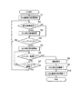
図1は、本発明を適用した実施形態1の撮像装置100の概略構成を示すブロック図である。
実施形態1の撮像装置100は、撮像部1のCCD12aのぶれ検出領域A2(図3参照)から得られる画像データに基づいて撮像画像のぶれ量を検出し、検出されたぶれ量に応じてCCD12aの主撮像領域A1(図3参照)から得られる画像データにぶれ補正処理を施し、被写体の撮像画像のぶれを補正するものである。
具体的には、撮像装置100は、図1に示すように、撮像部1と、撮像補助部2と、表示部3と、操作部4と、記録媒体5と、USB端子6と、制御部7等を備えて構成されている。
[Embodiment 1]
FIG. 1 is a block diagram illustrating a schematic configuration of an
The
Specifically, as illustrated in FIG. 1, the
撮像部1は、撮像者により撮像装置100が向けられた方向の被写体を撮像するものである。具体的には、撮像部1は、撮像レンズ群11と、電子撮像部12と、映像信号処理部13と、画像メモリ14と、撮像素子駆動部15と、撮像制御部16等を備えている。
The
撮像レンズ群11は、フォーカス機能及びズーム機能を有し、複数の撮像レンズから構成されている。
The
電子撮像部12は、撮像レンズ群11を通過した被写体像を二次元の画像信号に変換する撮像素子であるCCD(Charge Coupled Device)12a等から構成されている。
CCD12aは、撮像レンズ群11を通過した光を光量に応じて光電変換して蓄積する複数の光電変換部が二次元マトリックス状に配列されたものである。また、CCD12aは、被写体を撮像した際に、主撮像画像に係る主撮像データを保持する略矩形状の主撮像領域A1(図3参照)と、主撮像領域A1の外側(主撮像領域A1と異なる領域)に隣接して設けられ、画像ぶれに関するぶれ検出データを保持する略「ロ」字状のぶれ検出領域A2(図3参照)とを具備している。
そして、CCD12aは、例えば、CPU71の制御下にて、複数の光電変換部に蓄積された電荷が順次所定方向(例えば、垂直方向)に転送されて読み出される、いわゆる破壊読み出し可能に構成されている。
The
The
The
映像信号処理部13は、電子撮像部12から出力される画像信号に対して所定の画像処理を施すものである。
画像メモリ14は、画像処理後の画像信号を一時的に記憶する。
撮像素子駆動部15は、撮像素子であるCCD12aを所定方向(例えば、垂直方向および水平方向)に移動させるアクチュエータと、そのアクチュエータを駆動させるアクチュエータドライバ等から構成されている。
撮像制御部16は、CPU71の制御下にて、電子撮像部12、映像信号処理部13、撮像素子駆動部15を制御する。
The video
The
The image
The
撮像補助部2は、撮像部1による被写体の撮像の際に駆動するものであり、例えば、フォーカス駆動部21と、ズーム駆動部22等を備えている。
フォーカス駆動部21は、撮像レンズ群11に接続されたフォーカス機構部(図示略)を駆動させる。
ズーム駆動部22は、撮像レンズ群11に接続されたズーム機構部(図示略)を駆動させる。
なお、フォーカス駆動部21及びズーム駆動部22は、撮像制御部16に接続され、撮像制御部16の制御下にて駆動する。
The imaging
The
The
The
表示部3は、撮像部1により撮像された画像を表示するものであり、例えば、表示制御部31と、画像表示部32等を備えている。
表示制御部31は、CPU71から適宜出力される表示データを一時的に保存するビデオメモリ(図示略)を備えている。
画像表示部32は、表示制御部31からの出力信号に基づいて所定の画像を表示する液晶モニタ等を備えている。
The
The
The
操作部4は、当該撮像装置100の所定操作を行うためのものであり、例えば、シャッターボタン41a等の各種操作スイッチ等を備える操作入力部41と、入力回路42等を備えている。
操作入力部41におけるシャッターボタン41aは、撮像部1による被写体の撮像を指示する。このシャッターボタン41aは、半押し操作と全押し操作の2段階の押圧操作が可能に構成されている。
入力回路42は、この操作入力部41から入力された操作信号をCPU71に入力するためのものである。
The
A
The
記録媒体5は、例えば、カード型の不揮発性メモリ(フラッシュメモリ)やハードディスク等により構成され、画像記録部として、撮像部1により撮像された撮像画像の画像情報(画像データ)を記憶する。
The
USB端子6は、外部機器との接続用の端子であり、USBケーブル(図示略)等を介してデータの送受信を行う。
The
制御部7は、撮像装置100の各部を制御するものであり、例えば、CPU71と、プログラムメモリ72と、データメモリ73等を備えている。
The control unit 7 controls each unit of the
CPU71は、プログラムメモリ72に記憶された撮像装置100用の各種処理プログラムに従って各種の制御動作を行うものである。
The
データメモリ73は、例えば、フラッシュメモリ等により構成され、CPU71によって処理されるデータ等を一時記憶する。
The
プログラムメモリ72は、CPU71の動作に必要な各種プログラムやデータを記憶するものであり、具体的には、第一読出制御プログラム72a、第二読出制御プログラム72b、ぶれ量検出プログラム72c、ぶれ補正プログラム72d、画像情報取得プログラム72e、領域変更プログラム72f等を記憶している。
The
第一読出制御プログラム72aは、CPU71を第一読出制御手段として機能させるものである。即ち、第一読出制御プログラム72aは、スルー画像表示時には撮像部1により撮像される撮像画像の範囲に対応するCCD12aの撮像領域に予め設定されている主撮像領域A1から被写体の主撮像データを第1フレームレートで読み出す処理に係る機能、静止画の撮影時には所定の露光時間で露光して読み出す処理に係る機能をCPU71に実現させるためのプログラムである。
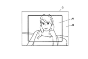
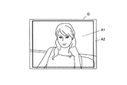
具体的には、図2に示すような被写体画像を撮像する際に、CCD12aの撮像領域が、例えば、図3に示すように、撮像画像Gに対する中央側に位置する主撮像領域A1と、主撮像領域A1の外周側を囲うぶれ検出領域A2とからなるように設定されている場合、CPU71は、CCD12aにおける主撮像領域A1に保持された主撮像データを所定の第1フレームレートで読み出して取得、又は所定の露光時間で露光して読み出すことにより取得する。
The first read control program 72a causes the
Specifically, when imaging a subject image as shown in FIG. 2, the imaging area of the
第二読出制御プログラム72bは、CPU71を第二読出制御手段として機能させるものである。即ち、第二読出制御プログラム72bは、撮像部1により撮像される撮像画像の範囲に対応するCCD12aの撮像領域に予め設定されているぶれ検出領域A2からぶれ検出データを第1フレームレートより速い第2フレームレートで読み出す処理に係る機能、静止画の撮影時に主撮像データの露光時間中にぶれ検出データを所定のフレームレートで読み出す処理に係る機能をCPU71に実現させるためのプログラムである。
具体的には、図2に示すような被写体画像を撮像する際に、CPU71は、CCD12aにおけるぶれ検出領域A2に保持されたぶれ検出データを第2フレームレートで読み出して取得、又は主画像データの露光時間中にぶれ検出データを所定のフレームレートで読み出して取得する。
ここで、ぶれ検出領域A2は、例えば、図3に示すように、主撮像領域A1と重ならない配置に設定されているため、ぶれ検出領域A2に対応する画像情報が破壊読み出しされても、主撮像領域A1に対応する画像情報が損なわれることがないので、主撮像領域A1から被写体の撮像データを良好に読み出して、取得することが可能である。
そして、図4に示すように、シャッター前のスルー画像表示時においては、ぶれ検出領域A2に対しては、主撮像領域A1に比べて短時間の露光による比較的速いフレームレートにより撮像画像データを読み出して、その画像に関する画素の取り込みが行われる。
またシャッター後の静止画撮影時においても、ぶれ検出領域A2は、主撮像領域A1の撮像露光時間中に、1回の露光時間が主画像領域A1よりも短時間で且つ1回より多くの回数撮影画像データを読み出して、その画像に関する画素の取り込みが行われる。
なお、ぶれ検出領域A2からの画像ぶれに関するぶれ検出データの読み出しに当たって、ゲイン調整され感度が高められていることが好ましい。
The second
Specifically, when the subject image as shown in FIG. 2 is captured, the
Here, for example, as shown in FIG. 3, the shake detection area A2 is set to an arrangement that does not overlap with the main imaging area A1, so that even if the image information corresponding to the shake detection area A2 is read out destructively, Since the image information corresponding to the imaging area A1 is not impaired, it is possible to read and acquire the imaging data of the subject from the main imaging area A1.
As shown in FIG. 4, when the through image is displayed before the shutter, the captured image data is captured in the blur detection area A2 at a relatively fast frame rate by a short exposure compared to the main imaging area A1. Reading is performed, and pixels relating to the image are captured.
Even during still image shooting after the shutter, the blur detection area A2 has a shorter exposure time than the main image area A1 and more times than one time during the imaging exposure time of the main imaging area A1. The captured image data is read out, and pixels relating to the image are captured.
It should be noted that, when reading blur detection data relating to image blur from the blur detection area A2, it is preferable that the gain is adjusted to increase sensitivity.
ぶれ量検出プログラム72cは、CPU71をぶれ量検出手段として機能させるものである。即ち、ぶれ量検出プログラム72cは、CPU71の制御により撮像部1で撮像された撮像画像Gにおけるぶれ検出領域A2から得られたぶれ検出データに基づき、画像ぶれ量を検出するぶれ量検出処理に係る機能をCPU71に実現させるためのプログラムである。
このCPU71は、例えば、撮像画像Gにおけるぶれ検出領域A2から第2フレームレートで読み出された画像ぶれに関するぶれ検出データであって、第2フレームレートで連続的に読み出された複数の撮像画像データに基づき、ぶれ検出領域A2における特定画素の移動量を検出するようにして撮像画像Gの画像ぶれ量を検出する。
The shake
The
ぶれ補正プログラム72dは、CPU71をぶれ補正手段として機能させるものである。即ち、ぶれ補正プログラム72dは、検出された画像ぶれ量に応じた補正処理を行うぶれ補正処理に係る機能をCPU71に実現させるためのプログラムである。
このCPU71は、例えば、検出された画像ぶれ量に基づき電子撮像部12におけるCCD12aの移動量を算出し、当該移動量に応じて撮像素子駆動部15によりCCD12aを移動させて、撮像装置100のぶれや被写体のぶれを相殺するようにして撮像画像Gのぶれ補正を実行する。
The
For example, the
画像情報取得プログラム72eは、CPU71を画像情報取得手段として機能させるものである。即ち、画像情報取得プログラム72eは、CPU71による補正処理により、画像ぶれが補正された主撮像データに基づく画像情報を取得する画像情報取得処理に係る機能をCPU71に実現させるためのプログラムである。
このCPU71は、例えば、補正処理が実行されて、撮像部1によって撮像された撮像画像Gにおける主撮像領域A1から第1フレームレートで読み出された主撮像データである被写体の撮像画像データを取得して記録媒体5に記憶させる。つまり、CPU71は、撮像画像Gにおける主撮像領域A1部分に対応する画像を記録画像として取得する。
The image
The
領域変更プログラム72fは、CPU71を領域変更手段として機能させるものである。即ち、領域変更プログラム72fは、撮像画像Gの範囲に対応するようにCCD12aに対して予め設定されている主撮像領域A1とぶれ検出領域A2とに区分けされた2つの領域におけるぶれ検出領域A2の大きさを変更する領域変更処理に係る機能をCPU71に実現させるためのプログラムである。なお、主撮像領域A1とぶれ検出領域A2とは撮像画像範囲において重ならない配置をとるので、変更されたぶれ検出領域A2の大きさに応じて、主撮像領域A1の大きさも変更されることとなる。つまり、例えば、ぶれ検出領域A2が大きくなれば、主撮像領域A1は小さくなる。特に、このCPU71は、検出された画像ぶれ量に応じて、ぶれ検出領域A2の大きさを変更する処理を実行する。
The
次に、本実施形態における撮像装置100において、被写体としての人物を撮像する際の処理について、図5に示すフローチャートに基づき説明する。
Next, processing when the person as the subject is imaged in the
まず、ユーザ(撮像者)による所定操作によって撮像装置100を所望する被写体である人物に向けると、撮像レンズ群11を通じて電子撮像部12に結像された画像が、図2に示すように、表示部3の画像表示部32の表示画面にスルー画像となって表示される。
そして、CPU71は、プログラムメモリ72から第二読出制御プログラム72bを読み出して実行し、CCD12aの撮像領域におけるぶれ検出領域A2(図3参照)から画像ぶれに関するぶれ検出データを読み出して取得する。さらに、CPU71は、プログラムメモリ72からぶれ量検出プログラム72cを読み出して実行し、ぶれ検出領域A2から第2フレームレートで読み出された画像ぶれに関するぶれ検出データに基づき、撮像画像Gの画像ぶれ量の検出処理を開始する(ステップS1)。
First, when the
Then, the
次いで、CPU71は、操作入力部41における切り替え操作に基づいて、ぶれ検出領域A2の変更処理の実行が指示されているか否かを判定する(ステップS2)。
CPU71が、ぶれ検出領域A2の変更処理の実行が指示されていないと判定すると(ステップS2;No)、ステップS4へ進む。
一方、CPU71が、ぶれ検出領域A2の変更処理の実行が指示されていると判定すると(ステップS2;Yes)、CPU71は、プログラムメモリ72から領域変更プログラム72fを読み出して実行し、画像ぶれ量に応じたぶれ検出領域A2の変更を行う(ステップS3)。例えば、検出された画像ぶれ量が所定の基準より大きい場合、撮像画像Gの画像ぶれ量を適正に検出することができるように、図6に示すように、ぶれ検出領域A2を大きくする変更を行う。また、検出された画像ぶれ量が所定の基準より小さい場合、図6に示すように、撮像画像Gの画像ぶれ量を精度よく検出することができるように、ぶれ検出領域A2を大きくする変更を行ってもよい。また、ぶれ検出領域の大きさ変更は、手動で行ってもよい。
なお、ぶれ検出領域A2が小さいほど画像ぶれ量の検出処理を短時間で行うことができるので、図7に示すように、検出された画像振れ量が所定の基準より小さい場合、撮像画像Gの画像振れ量を適正に検出することが可能な程度に、振れ検出エリアA2を小さくする変更を行ってもよい。
Next, the
If the
On the other hand, when the
Note that, as the blur detection area A2 is smaller, the image blur amount detection process can be performed in a shorter time. Therefore, when the detected image blur amount is smaller than a predetermined reference as illustrated in FIG. You may perform the change which makes shake detection area A2 small to such an extent that an image shake amount can be detected appropriately.
ステップS4において、CPU71は、ユーザの操作によりシャッターボタン41aが半押しされたハーフシャッタとなったか否かを判断する(ステップS4)。
CPU71が、ハーフシャッタとなっていないと判断すると(ステップS4;No)、ステップS2に戻る。
一方、CPU71が、ハーフシャッタとなったと判断すると(ステップS4;Yes)、CPU71は、プログラムメモリ72からぶれ補正プログラム72dを読み出して実行し、検出された画像ぶれ量に基づき算出した移動量に応じてCCD12aを移動させるぶれ補正処理を開始する(ステップS5)。
In step S4, the
When the
On the other hand, when the
次いで、CPU71は、ユーザの操作によりシャッターボタン41aが全押しされ、撮像操作が行われたか否かを判断する(ステップS6)。
CPU71が、シャッターボタン41aが全押しされたと判断すると(ステップS6;Yes)、ステップS8へ進む。
一方、CPU71が、シャッターボタン41aは全押しされていないと判断すると(ステップS6;No)、CPU71は、シャッターボタン41aが半押しされたハーフシャッタが解除されたか否かを判断する(ステップS7)。
CPU71が、ハーフシャッタは解除されていないと判断すると(ステップS7;No)、ステップS6に戻る。一方、CPU71が、ハーフシャッタは解除されたと判断すると(ステップS7;Yes)、ステップS2に戻る。
Next, the
When the
On the other hand, when the
When the
ステップS8において、CPU71は、プログラムメモリ72から、第一読出制御プログラム72aと画像情報取得プログラム72eを読み出して実行し、シャッターボタン41aが全押しされたタイミングに、被写体の撮像を実行して、撮像レンズ群11を通じて電子撮像部12の主撮像領域A1(図3参照)に結像されている主撮像画像に関する主撮像データであって、CPU71による補正処理により画像ぶれが補正された画像情報を読み出し取得して記録媒体5に記録する(ステップS8)。
In step S8, the
そして、ユーザによるシャッターボタン41aの全押しが解除されると、CPU71は、ぶれ補正処理を終了した後(ステップS9)、画像ぶれ量の検出処理を終了して(ステップS10)、撮像処理を終了する。
When the user fully releases the
以上のように、この実施形態1の撮像装置100によれば、CCD12aのぶれ検出領域A2から読み出したぶれ検出データに基づく画像ぶれ量に応じてCCD12aを移動させて、撮像装置100のぶれや被写体のぶれを相殺することによる撮像画像のぶれ補正処理を実行することができ、そのぶれ補正処理によって画像ぶれが補正されている撮像画像が結像されたCCD12aの主撮像領域A1から主撮像データを読み出して、所望する被写体の画像情報を取得することができる。
つまり、撮像装置100は、撮像部1により撮像される撮像画像Gの範囲に対応するCCD12aの撮像領域に予め設定されている主撮像領域A1とぶれ検出領域A2とからそれぞれ撮像画像の画像データを読み取り、ぶれ検出領域A2から得られるブレ検出データに基づき画像ぶれ量を取得し、取得した画像ぶれ量に応じた補正を主撮像領域A1から得られる主撮像データに対して施すようにして、画像ぶれのない好適な被写体の画像情報を取得する撮像を可能にする。
特に、撮像装置100において、撮像領域に対して互いに重ならない主撮像領域A1とぶれ検出領域A2を設定するとともに、被写体の撮像データを第1フレームレートで主撮像領域A1から読み出すことと、画像ぶれに関するぶれ検出データを第1フレームレートより速い第2フレームレートでぶれ検出領域A2から読み出すことを、撮像素子であるCCD12aによって可能にして、ジャイロを不要とするので、コスト低減とスペース有効活用(小型化)を可能にする撮像装置100とすることができる。
As described above, according to the
That is, the
In particular, in the
そして、従来技術のようなジャイロなどの手ぶれ検出センサを備える撮像装置によっては、撮像装置側がぶれてしまう画像ぶれの補正(いわゆる手ぶれ補正)を行うことしかできないが、この撮像装置100は、撮像部1により撮像される撮像画像に基づく画像ぶれを補正する処理が可能であるので、撮像装置100側のぶれと被写体側のぶれの両方の画像ぶれを補正することができる。
また、撮像装置100は、検出された画像ぶれ量に応じて、ぶれ検出領域A2の大きさを変更することができるので、画像ぶれ量が大きい場合や小さい場合など、それぞれのぶれ量に適した画像ぶれの補正処理を行うことが可能になる。
従って、この撮像装置100であれば、ジャイロなどのセンサを用いることなく、画像ぶれの補正を好適に行うことができる。
Then, depending on an imaging apparatus having a camera shake detection sensor such as a gyro as in the prior art, it is only possible to perform image blur correction (so-called camera shake correction) in which the imaging apparatus side is blurred. Since it is possible to correct the image blur based on the captured image captured by 1, it is possible to correct both the image blur on the
In addition, since the
Therefore, with this
[実施形態2]
図8は、本発明を適用した実施形態2の撮像装置200の概略構成を示すブロック図である。
実施形態2の撮像装置200は、CMOS12bの撮像領域A3(図9参照)に含まれるぶれ検出領域A4(図9参照)から得られる画像データに基づいて撮像画像のぶれ量を検出し、検出されたぶれ量に応じて撮像領域A3から得られる画像データにぶれ補正処理を施し、被写体の撮像画像のぶれを補正するものである。
なお、実施形態2の撮像装置200は、撮像素子としてCMOS12bを用い、撮像領域A3にぶれ検出領域A4が含まれている以外の点では、実施形態1におけるものと略同様であるので、異なる部分について説明し、詳細な説明については省略するものとする。
[Embodiment 2]
FIG. 8 is a block diagram illustrating a schematic configuration of an
The
The
この撮像装置200における電子撮像部12は、撮像レンズ群11を通過した被写体像を二次元の画像信号に変換する撮像素子であるCMOS(Complementary Metal-Oxide Semiconductor)12b等から構成されている。
CMOS12bは、撮像レンズ群11を通過した光を光量に応じて光電変換して蓄積する複数の光電変換部が二次元マトリックス状に配列されたものである。また、CMOS12bは、被写体を撮像した際に、撮像画像に係る撮像データを保持する撮像領域A3を備え、撮像領域A3の内側の所定位置に、画像ぶれに関するぶれ検出データを保持するぶれ検出領域A4を具備している。
そして、CMOS12bは、例えば、CPU71の制御下にて、複数の光電変換部における任意の光電変換部の電荷が読み出される、いわゆる非破壊読み出し可能に構成されている。つまり、CMOS12bの複数の光電変換部のうち、特定の光電変換部の電荷のみが読み出されても、当該光電変換部には電荷が保持されるようになっている。
なお、被写体を撮像する範囲に対応する撮像領域を主撮像領域とぶれ検出領域との異なる2つの領域に区分けしてもよい。
The
The
The
Note that the imaging area corresponding to the range in which the subject is imaged may be divided into two different areas, the main imaging area and the shake detection area.
プログラムメモリ72は、CPU71の動作に必要な各種プログラムやデータを記憶するものであり、具体的には、第一読出制御プログラム72g、第二読出制御プログラム72h、ぶれ量検出プログラム72i、ぶれ補正プログラム72j、画像情報取得プログラム72k、領域変更プログラム72l、大ぶれ検出領域拡大プログラム72m、小ぶれ検出領域拡大プログラム72n等を記憶している。
The
そして、第一読出制御プログラム72gは、CPU71を第一読出制御手段として機能させるものである。即ち、第一読出制御プログラム72gは、撮像部1により撮像される撮像画像の範囲に対応するCMOS12bの撮像領域A3から被写体の撮像データを読み出す処理に係る機能をCPU71に実現させるためのプログラムである。
具体的には、図2に示すような被写体画像を撮像する際に、例えば、図9に示すように、CPU71は、CMOS12bにおける撮像領域A3に保持された撮像データを所定のフレームレートで読み出して取得する。
The first
Specifically, when capturing a subject image as shown in FIG. 2, for example, as shown in FIG. 9, the
第二読出制御プログラム72hは、CPU71を第二読出制御手段として機能させるものである。即ち、第二読出制御プログラム72hは、撮像部1により撮像される撮像画像の範囲に対応するCMOS12bの撮像領域A3に予め設定されているぶれ検出領域A4からぶれ検出データを読み出す処理に係る機能をCPU71に実現させるためのプログラムである。
具体的には、図2に示すような被写体画像を撮像する際に、その撮像領域が、例えば、図9に示すように、CMOS12bの撮像画像Gに係る画像情報を保持する撮像領域A3の4隅にぶれ検出領域A4が設定されている場合、CPU71は、ぶれ検出領域A4に保持されたぶれ検出データを所定のぶれ検出用のフレームレートで読み出して取得する。
ここで、CMOS12bは、非破壊読み出し可能な撮像素子であるため、撮像領域A3に重なった配置のぶれ検出領域A4から画像ぶれに関するぶれ検出データを読み出す処理を行っても、撮像領域A3から被写体の撮像データを読み出す処理を妨げることはなく、撮像データを良好に読み出して取得することが可能である。
ここで撮像領域A3の4隅にぶれ検出領域A4が設定されていなくても構わず、例えば十字状にぶれ検出領域を並べるように設定してもよい。
The second
Specifically, when a subject image as illustrated in FIG. 2 is captured, the imaging region is, for example, 4 in the imaging region A3 that holds image information related to the captured image G of the
Here, since the
Here, the blur detection areas A4 may not be set at the four corners of the imaging area A3. For example, the blur detection areas may be set in a cross shape.
また、ぶれ量検出プログラム72iは、CPU71をぶれ量検出手段として機能させるものであって、ぶれ量検出プログラム72iを実行するCPU71は、CPU71の制御によりCMOS12bのぶれ検出領域A4から読み出された画像ぶれに関するぶれ検出データであって、所定のぶれ検出用のフレームレートで読み出された複数の撮像画像データに基づき、ぶれ検出領域A4における特定画素の移動量を検出するようにして、撮像画像Gの画像ぶれ量を検出する。
Further, the shake
また、ぶれ補正プログラム72jは、CPU71をぶれ補正手段として機能させるものであって、ぶれ補正プログラム72jを実行するCPU71は、検出された画像ぶれ量に基づき電子撮像部12におけるCMOS12bの移動量を算出して、当該移動量に応じて撮像素子駆動部15によりCMOS12bを移動させて、撮像装置200のぶれや被写体のぶれを相殺するようにして撮像画像Gのぶれ補正を実行する。
The
また、画像情報取得プログラム72kは、CPU71を画像情報取得手段として機能させるものであって、画像情報取得プログラム72kを実行するCPU71は、補正処理が実行されて、CMOS12bの撮像領域A3から所定の撮像用のフレームレートで読み出された撮像データである被写体の撮像画像データを記録媒体5に記憶させて、被写体を撮像した記録画像に関する画像情報を取得する。
The image
また、領域変更プログラム72lは、CPU71を領域変更手段として機能させるものであって、領域変更プログラム72lを実行するCPU71は、撮像画像Gの範囲に対応して予め設定されているぶれ検出領域A4の大きさと形状の少なくとも一方を変更する処理を実行する。特に、CMOS12bは、非破壊読み出し可能な撮像素子であるため、撮像領域A3にぶれ検出領域A4が含まれる(重なった)配置となってもよいので、ぶれ検出領域A4の大きさや形状、その配置位置に関する自由度が高く、所望するぶれ検出領域A4に変更設定することが可能となる。
なお、ぶれ検出領域の変更は、手振れ量に応じて自動で行ってもよいし、手動で行ってもよい。
The area change program 72l causes the
The shake detection area may be changed automatically according to the amount of camera shake or manually.
また、大ぶれ検出領域拡大プログラム72mは、CPU71を領域変更手段の一部であるぶれ検出領域拡大手段として機能させるものであって、大ぶれ検出領域拡大プログラム72mを実行するCPU71は、検出された画像ぶれ量が所定の基準値より大きい場合に、ぶれ検出領域A4を大きくするぶれ検出領域拡大処理を実行する。
つまり、このCPU71は、検出された画像ぶれ量が大きい場合に、図10に示すように、ぶれ検出領域A4を大きくする変更を行い、ぶれ検出領域A4における特定画素の移動量が大きい場合であっても、そのぶれ検出領域A4内で特定画素の移動を検出可能にするようにして、撮像画像の画像ぶれ量を適正に検出するようになっている。このように、ぶれ検出領域A4を大きくする変更によって、大きな画像ぶれを適正に補正するが可能になる。
The shake detection
That is, when the detected amount of image blur is large, the
また、小ぶれ検出領域拡大プログラム72nは、CPU71を領域変更手段の一部である微小ぶれ検出領域拡大手段として機能させるものであって、小ぶれ検出領域拡大プログラム72nを実行するCPU71は、検出された画像ぶれ量が所定の基準値より小さい場合に、ぶれ検出領域A4を大きくする微小ぶれ検出領域拡大処理を実行する。
つまり、このCPU71は、検出された画像ぶれ量が小さい場合に、図10に示すように、ぶれ検出領域A4を大きくする変更を行い、ぶれ検出領域A4における特定画素の移動量が小さい場合であっても、そのぶれ検出領域A4内での特定画素の微小な移動も検出可能とするようにして、撮像画像の画像ぶれ量を精度よく検出するようになっている。このように、ぶれ検出領域A4を大きくする変更によって、小さな画像ぶれでも正確に補正することが可能になる。
Further, the camera shake detection
That is, when the detected image blur amount is small, the
なお、ぶれ検出領域A4が小さいほど画像ぶれ量の検出処理を短時間で行うことができるので、図11に示すように、検出された画像振れ量が所定の基準より小さい場合、撮像画像Gの画像振れ量を適正に検出することが可能な程度に、ぶれ検出領域A4を小さくする変更を行ってもよい。 Note that, as the blur detection area A4 is smaller, the image blur amount detection process can be performed in a shorter time. Therefore, as shown in FIG. 11, when the detected image blur amount is smaller than a predetermined reference, the captured image G You may make the change which makes blur detection area A4 small to such an extent that an image shake amount can be detected appropriately.
また、検出された画像ぶれ量が大きい場合に撮像画像の画像ぶれ量を適正に検出するためにぶれ検出領域A2を大きくする変更を行うことと、検出された画像ぶれ量が小さい場合に撮像画像の画像ぶれ量を精度よく検出するためにぶれ検出領域A2を大きくする変更を行うこととは、ユーザが優先する撮像条件や、被写体の大きさや動きに関する条件に応じて、選択して切り替えるようにすればよい。 Further, when the detected image blur amount is large, a change is made to increase the blur detection area A2 in order to properly detect the image blur amount of the captured image, and when the detected image blur amount is small, the captured image In order to accurately detect the amount of image blur, the change to increase the blur detection area A2 is selected and switched in accordance with the imaging conditions prioritized by the user and the conditions regarding the size and movement of the subject. do it.
以上のように、実施形態2の撮像装置200によれば、撮像画像Gにおけるぶれ検出領域A4から読み出したぶれ検出データに基づく画像ぶれ量に応じてCMOS12bを移動させて、撮像装置200のぶれや被写体のぶれを相殺することによる撮像画像のぶれ補正処理を実行することができ、そのぶれ補正処理によって画像ぶれが補正されている撮像画像が結像されたCMOS12bにおける撮像領域A3から撮像データを読み出して、所望する被写体の画像情報を取得することができる。
特に、撮像装置200は、非破壊読み出し可能な撮像素子であるCMOS12bを用いることにより、撮像領域A3に重なった配置のぶれ検出領域A4から画像ぶれに関するぶれ検出データを読み出す処理を行っても、撮像領域A3から被写体の撮像データを読み出す処理を妨げることはないので、好適な画像ぶれの検出が可能となるようにぶれ検出領域A4を任意に設定することができる。そして、好適な画像ぶれの検出に伴い好適な画像ぶれの補正がなされて、画像ぶれのない良好な被写体の画像情報を取得する撮像を行うことが可能になる。
従って、このような撮像装置200であっても、ジャイロなどのセンサを用いることなく、画像ぶれの補正を好適に行うことができ、ジャイロを不要とすることにより、コスト低減とスペース有効活用を可能にする撮像装置200とすることができる。
As described above, according to the
In particular, the
Therefore, even with such an
なお、本発明は、上記実施形態に限定されることなく、本発明の趣旨を逸脱しない範囲において、種々の改良並びに設計の変更を行ってもよい。
実施形態1及び2においては、取得した画像ぶれ量に応じて、CCD12aやCMOS12bを移動させる撮像素子シフトによるぶれ補正処理を例に挙げて説明したが、本発明はこれに限定されるものではなく、例えば、画像ぶれ量に基づき算出された移動量に応じて撮像レンズ群11を移動させるレンズシフトによるぶれ補正処理であってもよい。また、取得した画像ぶれ量に応じて、撮像した主撮像領域に関する複数の画像情報を重ね合わせるデジタル合成を行う電子式の画像補正処理であってもよい。
また、実施形態1及び2においては、図5にあるように、スルー画像表示や静止画撮影のために本発明の手振れ検出方法を用いたがこれに限らず、連写撮影や動画撮影に関するものであってもよい。例えば動画撮影においては、主撮像領域は30fpsで画素の読み込みを行い、ぶれ検出領域は60fpsで画素の読み込みを行うように構成してもよい。この場合、動画撮影前のスルー画像においては、主撮像領域は15fpsで画素の読み込みを行い、ぶれ検出領域は30fpsで画素の読み込みを行うように構成しておき、シャッターボタンを押下して撮影開始した場合に各フレームレートを変更する構成としてもよい。この時、主撮像領域のフレームレートと、ぶれ検出領域のフレームレートを別々に変更可能に構成してもよく、これにより所望の条件で撮影することができる。
The present invention is not limited to the above-described embodiment, and various improvements and design changes may be made without departing from the spirit of the present invention.
In the first and second embodiments, the blur correction process by the image sensor shift that moves the
In the first and second embodiments, as shown in FIG. 5, the camera shake detection method of the present invention is used for through image display and still image shooting. It may be. For example, in moving image shooting, the main imaging area may be configured to read pixels at 30 fps, and the blur detection area may be configured to read pixels at 60 fps. In this case, in the through image before moving image shooting, the main imaging area is configured to read pixels at 15 fps, and the blur detection area is configured to read pixels at 30 fps, and the shutter button is pressed to start shooting. In such a case, each frame rate may be changed. At this time, the frame rate of the main image pickup area and the frame rate of the shake detection area may be changed separately, thereby enabling shooting under desired conditions.
また、実施形態2にあっては、検出された画像ぶれ量に応じて、ぶれ検出領域を変更する際、検出された画像ぶれ量が縦方向(上下方向)のぶれであった場合に、ぶれ検出領域を縦方向に長くする変更処理を行い、ぶれ検出領域における特定画素の縦方向への移動を検出しやすくし、また、検出された画像ぶれ量が横方向(左右方向)のぶれであった場合に、ぶれ検出領域を横方向に長くする変更処理を行い、ぶれ検出領域における特定画素の横方向への移動を検出しやすくするようにしてもよい。 Further, in the second embodiment, when changing the blur detection area according to the detected image blur amount, if the detected image blur amount is a blur in the vertical direction (vertical direction), the blur is detected. Change processing to lengthen the detection area in the vertical direction makes it easier to detect the movement of specific pixels in the vertical direction in the shake detection area, and the detected image blur amount is horizontal (left-right) blur. In such a case, a change process for lengthening the shake detection area in the horizontal direction may be performed so that it is easy to detect the movement of the specific pixel in the horizontal direction in the shake detection area.
加えて、上記実施形態1及び2では、第一読出制御手段、第二読出制御手段、ぶれ量検出手段、ぶれ補正手段、画像情報取得手段、領域変更手段、ぶれ検出領域拡大手段、微小ぶれ検出領域拡大手段としての機能を、CPU71によって、所定のプログラム等が実行されることにより実現される構成としたが、これに限られるものではなく、例えば、各種機能を実現するためのロジック回路等から構成してもよい。
In addition, in the first and second embodiments, the first readout control unit, the second readout control unit, the shake amount detection unit, the shake correction unit, the image information acquisition unit, the region change unit, the shake detection region enlargement unit, the minute blur The function as the detection area expanding means is configured to be realized by executing a predetermined program or the like by the
1 撮像部
12 電子撮像部
12a CCD(撮像素子)
12b CMOS(撮像素子)
3 表示部
32 画像表示部
5 記録媒体
7 制御部
71 CPU(第一読出制御手段、第二読出制御手段、ぶれ量検出手段、ぶれ補正手段、画像情報取得手段、領域変更手段、大ぶれ検出領域拡大手段、小ぶれ検出領域拡大手段)
100、200 撮像装置
A1 主撮像領域
A2 ぶれ検出領域
A3 撮像領域
A4 ぶれ検出領域
G 撮像画像
1 imaging
12b CMOS (imaging device)
DESCRIPTION OF
100, 200 Imaging device A1 Main imaging area A2 Blur detection area A3 Imaging area A4 Blur detection area G Captured image
Claims (7)
前記撮像素子に、撮像画像に係る撮像データを取得する撮像領域と、画像ぶれに関するぶれ検出データを取得するぶれ検出領域と、を設定する領域設定手段と、
前記領域設定手段により設定された前記撮像領域から前記撮像データを所定の第1の周期毎に読み出す第一読出制御手段と、
前記領域設定手段で設定した前記ぶれ検出領域から前記ぶれ検出データを前記第1の周期より短い所定の第2の周期毎に読み出す第二読出制御手段と、
前記第二読出制御手段により前記ぶれ検出領域から前記所定の第2の周期毎に読み出された前記ぶれ検出データに基づき、画像ぶれ量を逐次検出するぶれ量検出手段と、
前記ぶれ量検出手段により検出された画像ぶれ量が所定の基準値以上又は所定の基準値未満かを逐次判定する判定手段と、
前記判定手段による判定結果に基づいて、前記領域設定手段により設定された前記ぶれ検出領域の大きさを逐次変更する領域変更手段と、
を備えることを特徴とする撮像装置。 An image sensor for imaging a subject;
An area setting means for setting an imaging area for acquiring imaging data relating to a captured image and a blur detection area for acquiring blur detection data related to image blur in the imaging element;
First readout control means for reading out the imaging data from the imaging area set by the area setting means for each predetermined first period ;
Second reading control means for reading out the shake detection data from the shake detection area set by the area setting means at every predetermined second period shorter than the first period ;
A blur amount detecting means for sequentially detecting an image blur amount based on the blur detection data read out from the blur detection region by the second readout control unit at each predetermined second period ;
A determination unit that sequentially determines whether the image blur amount detected by the blur amount detection unit is greater than or equal to a predetermined reference value or less than a predetermined reference value;
An area changing means for sequentially changing the size of the blur detection area set by the area setting means based on the determination result by the determining means;
An imaging apparatus comprising:
前記領域変更手段は、前記撮像領域の外周側を囲うように設定されたぶれ検出領域の大きさを変更することを特徴とする請求項1〜3の何れか一項に記載の撮像装置。 The imaging apparatus according to claim 1, wherein the area changing unit changes a size of a shake detection area set so as to surround an outer peripheral side of the imaging area.
前記ぶれ補正手段により画像ぶれが補正された前記撮像データに基づく画像情報を前記第一読出制御手段により読み出して取得する画像情報取得手段と、
を更に備えることを特徴とする請求項1〜4の何れか一項に記載の撮像装置。 A blur correction unit that performs a correction process according to the image blur amount detected by the blur amount detection unit;
Image information acquisition means for reading out and acquiring image information based on the imaging data in which image blur has been corrected by the blur correction means;
The imaging apparatus according to any one of claims 1 to 4, further comprising a.
前記第一読出制御手段により読み出した前記撮像データに基づく画像情報を取得して、前記ぶれ補正手段により画像ぶれを補正した画像情報を取得する画像情報取得手段と、
を更に備えることを特徴とする請求項1〜4の何れか一項に記載の撮像装置。 A blur correction unit that performs a correction process according to the image blur amount detected by the blur amount detection unit;
Image information acquisition means for acquiring image information based on the imaging data read by the first readout control means, and acquiring image information obtained by correcting image blur by the blur correction means;
The imaging apparatus according to any one of claims 1 to 4, further comprising a.
前記撮像素子に、撮像画像に係る撮像データを取得する撮像領域と、画像ぶれに関するぶれ検出データを取得するぶれ検出領域と、を設定する領域設定手段、
前記領域設定手段で設定した前記撮像領域から前記撮像データを所定の第1の周期毎に読み出す第一読出制御手段、
前記領域設定手段で設定した前記ぶれ検出領域から前記ぶれ検出データを前記第1の周期より短い所定の第2の周期毎に読み出す第二読出制御手段、
前記第二読出制御手段により前記ぶれ検出領域から前記所定の第2の周期毎に読み出された前記ぶれ検出データに基づき、画像ぶれ量を逐次検出するぶれ量検出手段、
前記ぶれ量検出手段により検出された画像ぶれ量が所定の基準値以上又は所定の基準値未満かを逐次判定する判定手段、
前記判定手段による判定結果に基づいて、前記領域設定手段により設定された前記ぶれ検出領域の大きさを逐次変更する領域変更手段、
として機能させることを特徴とするプログラム。 A computer having an image sensor for imaging a subject,
Area setting means for setting an imaging area for acquiring imaging data relating to a captured image and a blur detection area for acquiring blur detection data relating to image blur in the imaging element;
First readout control means for reading out the imaging data from the imaging area set by the area setting means for each predetermined first period ;
Second read control means for reading the shake detection data from the shake detection area set by the area setting means at every predetermined second period shorter than the first period ;
A blur amount detecting unit that sequentially detects an image blur amount based on the blur detection data read out from the blur detection region by the second reading control unit at each predetermined second period ;
A determination unit that sequentially determines whether the image blur amount detected by the blur amount detection unit is greater than or equal to a predetermined reference value or less than a predetermined reference value;
Area changing means for sequentially changing the size of the blur detection area set by the area setting means based on the determination result by the determining means;
A program characterized by functioning as
Priority Applications (1)
| Application Number | Priority Date | Filing Date | Title |
|---|---|---|---|
| JP2007092825A JP5217213B2 (en) | 2007-03-30 | 2007-03-30 | Imaging apparatus and program |
Applications Claiming Priority (1)
| Application Number | Priority Date | Filing Date | Title |
|---|---|---|---|
| JP2007092825A JP5217213B2 (en) | 2007-03-30 | 2007-03-30 | Imaging apparatus and program |
Publications (3)
| Publication Number | Publication Date |
|---|---|
| JP2008252648A JP2008252648A (en) | 2008-10-16 |
| JP2008252648A5 JP2008252648A5 (en) | 2010-05-13 |
| JP5217213B2 true JP5217213B2 (en) | 2013-06-19 |
Family
ID=39977047
Family Applications (1)
| Application Number | Title | Priority Date | Filing Date |
|---|---|---|---|
| JP2007092825A Expired - Fee Related JP5217213B2 (en) | 2007-03-30 | 2007-03-30 | Imaging apparatus and program |
Country Status (1)
| Country | Link |
|---|---|
| JP (1) | JP5217213B2 (en) |
Families Citing this family (6)
| Publication number | Priority date | Publication date | Assignee | Title |
|---|---|---|---|---|
| JP5184325B2 (en) * | 2008-12-11 | 2013-04-17 | 富士フイルム株式会社 | Image capturing apparatus, image capturing apparatus control method, and program |
| JP5482154B2 (en) | 2009-12-02 | 2014-04-23 | セイコーエプソン株式会社 | Imaging apparatus, imaging method, and imaging program |
| JP5790808B2 (en) * | 2014-02-18 | 2015-10-07 | セイコーエプソン株式会社 | Imaging device |
| EP3235239B1 (en) * | 2014-12-15 | 2022-02-02 | GVBB Holdings S.A.R.L | Image capture having improved perceived image sharpness |
| US10142568B2 (en) | 2017-02-13 | 2018-11-27 | Semiconductor Components Industries, Llc | Methods and apparatus for vignette and out-of-focus correction |
| WO2023218980A1 (en) * | 2022-05-13 | 2023-11-16 | ソニーセミコンダクタソリューションズ株式会社 | Imaging device, sensor chip, and processing circuit |
Family Cites Families (8)
| Publication number | Priority date | Publication date | Assignee | Title |
|---|---|---|---|---|
| JP2862241B2 (en) * | 1988-04-15 | 1999-03-03 | キヤノン株式会社 | Image blur detection device |
| JP2902966B2 (en) * | 1994-12-16 | 1999-06-07 | 三洋電機株式会社 | Camera shake correction device and video camera using the same |
| JP3627027B2 (en) * | 1996-10-17 | 2005-03-09 | コニカミノルタフォトイメージング株式会社 | Image detection system |
| JP3733828B2 (en) * | 2000-03-29 | 2006-01-11 | コニカミノルタフォトイメージング株式会社 | Electronic camera |
| JP2002027300A (en) * | 2000-07-05 | 2002-01-25 | Minolta Co Ltd | Digital camera |
| JP2004289709A (en) * | 2003-03-25 | 2004-10-14 | Toshiba Corp | Image pickup device, and image pickup method |
| JP2004336452A (en) * | 2003-05-08 | 2004-11-25 | Canon Inc | Imaging apparatus |
| JP4533089B2 (en) * | 2004-11-01 | 2010-08-25 | 富士通セミコンダクター株式会社 | Movie data generator |
-
2007
- 2007-03-30 JP JP2007092825A patent/JP5217213B2/en not_active Expired - Fee Related
Also Published As
| Publication number | Publication date |
|---|---|
| JP2008252648A (en) | 2008-10-16 |
Similar Documents
| Publication | Publication Date | Title |
|---|---|---|
| JP4818987B2 (en) | Imaging apparatus, display method, and program | |
| KR101237540B1 (en) | Camera equipped with image enlargind display function | |
| US8736741B2 (en) | Imaging device with contrast AF, and control method for imaging device with contrast AF | |
| JP2009284394A (en) | Imaging apparatus and imaging method | |
| JP5217213B2 (en) | Imaging apparatus and program | |
| JP2006287920A (en) | Video camera and image extracting apparatus utilized for the same | |
| US10298862B2 (en) | Imaging apparatus and imaging method | |
| TWI492618B (en) | Image pickup device and computer readable recording medium | |
| JP2009065573A (en) | Imaging apparatus, focus control method, and focus control program | |
| JP2009251491A (en) | Imaging apparatus and control method for imaging apparatus | |
| JP2009251493A (en) | Imaging apparatus and control method for imaging apparatus | |
| JP6296914B2 (en) | IMAGING DEVICE, IMAGING DEVICE CONTROL METHOD, AND PROGRAM | |
| JP2014026062A (en) | Imaging apparatus and imaging method | |
| JP6377286B2 (en) | Imaging apparatus, control method therefor, and operation program | |
| JP5197454B2 (en) | Digital camera | |
| JP2006245815A (en) | Imaging apparatus | |
| JP2006148550A (en) | Image processor and imaging device | |
| JP5478677B2 (en) | IMAGING DEVICE AND IMAGING DEVICE CONTROL METHOD | |
| JP5621265B2 (en) | Camera shake correction apparatus, imaging processing method, and program | |
| JP2009284117A (en) | Imaging device and method of controlling imaging device | |
| JP4985716B2 (en) | Imaging apparatus, method for setting focus evaluation area, and program | |
| JP2010226185A (en) | Imaging apparatus, and method of controlling imaging apparatus | |
| JP2010171769A (en) | Electronic camera | |
| JP4687619B2 (en) | Image processing apparatus, image processing method, and program | |
| JP5792273B2 (en) | Camera system |
Legal Events
| Date | Code | Title | Description |
|---|---|---|---|
| A521 | Request for written amendment filed |
Free format text: JAPANESE INTERMEDIATE CODE: A523 Effective date: 20100325 |
|
| A621 | Written request for application examination |
Free format text: JAPANESE INTERMEDIATE CODE: A621 Effective date: 20100325 |
|
| A977 | Report on retrieval |
Free format text: JAPANESE INTERMEDIATE CODE: A971007 Effective date: 20110729 |
|
| A131 | Notification of reasons for refusal |
Free format text: JAPANESE INTERMEDIATE CODE: A131 Effective date: 20110802 |
|
| A521 | Request for written amendment filed |
Free format text: JAPANESE INTERMEDIATE CODE: A523 Effective date: 20110926 |
|
| RD02 | Notification of acceptance of power of attorney |
Free format text: JAPANESE INTERMEDIATE CODE: A7422 Effective date: 20110926 |
|
| A131 | Notification of reasons for refusal |
Free format text: JAPANESE INTERMEDIATE CODE: A131 Effective date: 20120515 |
|
| A521 | Request for written amendment filed |
Free format text: JAPANESE INTERMEDIATE CODE: A523 Effective date: 20120710 |
|
| TRDD | Decision of grant or rejection written | ||
| A01 | Written decision to grant a patent or to grant a registration (utility model) |
Free format text: JAPANESE INTERMEDIATE CODE: A01 Effective date: 20130205 |
|
| A61 | First payment of annual fees (during grant procedure) |
Free format text: JAPANESE INTERMEDIATE CODE: A61 Effective date: 20130218 |
|
| FPAY | Renewal fee payment (event date is renewal date of database) |
Free format text: PAYMENT UNTIL: 20160315 Year of fee payment: 3 |
|
| R150 | Certificate of patent or registration of utility model |
Ref document number: 5217213 Country of ref document: JP Free format text: JAPANESE INTERMEDIATE CODE: R150 Free format text: JAPANESE INTERMEDIATE CODE: R150 |
|
| LAPS | Cancellation because of no payment of annual fees |