JP5214829B2 - Snuffback valve assembly - Google Patents
Snuffback valve assembly Download PDFInfo
- Publication number
- JP5214829B2 JP5214829B2 JP2001118279A JP2001118279A JP5214829B2 JP 5214829 B2 JP5214829 B2 JP 5214829B2 JP 2001118279 A JP2001118279 A JP 2001118279A JP 2001118279 A JP2001118279 A JP 2001118279A JP 5214829 B2 JP5214829 B2 JP 5214829B2
- Authority
- JP
- Japan
- Prior art keywords
- valve
- snuffback
- valve element
- seat member
- valve seat
- Prior art date
- Legal status (The legal status is an assumption and is not a legal conclusion. Google has not performed a legal analysis and makes no representation as to the accuracy of the status listed.)
- Expired - Lifetime
Links
Images


Classifications
-
- F—MECHANICAL ENGINEERING; LIGHTING; HEATING; WEAPONS; BLASTING
- F16—ENGINEERING ELEMENTS AND UNITS; GENERAL MEASURES FOR PRODUCING AND MAINTAINING EFFECTIVE FUNCTIONING OF MACHINES OR INSTALLATIONS; THERMAL INSULATION IN GENERAL
- F16K—VALVES; TAPS; COCKS; ACTUATING-FLOATS; DEVICES FOR VENTING OR AERATING
- F16K23/00—Valves for preventing drip from nozzles
-
- B—PERFORMING OPERATIONS; TRANSPORTING
- B05—SPRAYING OR ATOMISING IN GENERAL; APPLYING FLUENT MATERIALS TO SURFACES, IN GENERAL
- B05C—APPARATUS FOR APPLYING FLUENT MATERIALS TO SURFACES, IN GENERAL
- B05C5/00—Apparatus in which liquid or other fluent material is projected, poured or allowed to flow on to the surface of the work
- B05C5/02—Apparatus in which liquid or other fluent material is projected, poured or allowed to flow on to the surface of the work the liquid or other fluent material being discharged through an outlet orifice by pressure, e.g. from an outlet device in contact or almost in contact, with the work
- B05C5/0225—Apparatus in which liquid or other fluent material is projected, poured or allowed to flow on to the surface of the work the liquid or other fluent material being discharged through an outlet orifice by pressure, e.g. from an outlet device in contact or almost in contact, with the work characterised by flow controlling means, e.g. valves, located proximate the outlet
Landscapes
- Engineering & Computer Science (AREA)
- General Engineering & Computer Science (AREA)
- Mechanical Engineering (AREA)
- Lift Valve (AREA)
- Coating Apparatus (AREA)
- Safety Valves (AREA)
- Fluid-Driven Valves (AREA)
- Nozzles (AREA)
- Adhesives Or Adhesive Processes (AREA)
- Self-Closing Valves And Venting Or Aerating Valves (AREA)
Abstract
Description
本発明は、ホットメルト接着剤を供給する装置に一般に関し、とりわけ、望ましくない接着剤の糸引きが起こらないように、弁操作の終わり及び弁の閉鎖中に接着剤の供給を迅速に遮断できるホットメルト接着剤を供給する新規の改良したスナフバック弁に関する。 The present invention relates generally to an apparatus for supplying hot melt adhesives, and in particular, the supply of adhesive can be quickly shut off at the end of valve operation and during valve closure so that undesired adhesive stringing does not occur. It relates to a new and improved snuffback valve for supplying hot melt adhesives.
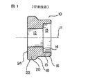
例えばホットメルト接着剤などの高粘性材料の供給に関して、供給装置はスナフバック弁として当業界で公知であるものを備え、この弁を用いると、弁の閉鎖時において、供給される接着剤が容易に遮断され、それにより、どうしても接着剤の糸引きが生じてしまう。公知の従来技術のスナフバック弁の一タイプが図1に開示されており、このスナフバック弁は参照番号10で全体的に示されている。スナフバック弁10は、図示しない弁ステムに固定的に取り付けられ、このステムは、図示しない例えばピストンドライブに固定的に接続され、それにより、スナフバック弁は、弁シートに関して開放位置と閉鎖位置を実現するように、図示しない弁シート部材に関して直線的に移動される。 For example, with respect to the supply of highly viscous materials such as hot melt adhesives, the supply device comprises what is known in the art as a snuff back valve, which makes it easy to supply adhesive when the valve is closed. This will cause the threading of the adhesive to occur. One type of known prior art snuffback valve is disclosed in FIG. 1 and is generally indicated by the
とりわけ、従来技術のスナフバック弁10は、軸線11を有するほぼ筒状の構造を備え、第一ボア12と、第一ボア12との間に形成されている肩部14を有する第二の座ぐり部13とを備えている。図示しない弁ステムは、座ぐり部13を通って延び、ステムの弁端部は肩部14上に着座される。図示しないボルトタイプのファスナがボア12を通って延び、弁ステムを弁10内に固定的に取り付けるように、図示しない弁ステムの弁端部と螺合する。弁10は、外側周縁筒状面部16を有する筒状スロート部15をさらに備えている。接着剤の流れを完了する時に弁シート部材と協働するようにスナフバック弁10が閉鎖位置に移動させられる時に、外側面部16は図示しない弁シート部材の内部に配置されるようにされている。例えば0.254mm(0.01インチ)の環状公差、間隙又は空間が、弁10のスナフバック作用を規定又は決定すると共に、弁の開放サイクル及び閉鎖サイクル中、図示しない弁シート部材に関してスナフバック弁10の直線的な運動を容易に許容するように、スナフバック弁10の外側筒状面部16と図示しない弁シート部材の内側周縁筒状面部との間で形成されている。スロート部15の下流では、スナフバック弁10は、スナフバック弁10が閉鎖位置に配置されそれゆえ弁シート部材に着座される時、図示しない弁シート部材の相補的な形状の切頭円錐形状面部と係合させられる外側切頭円錐面部18を備えている。 In particular, the prior
さらに、スナフバック弁10は、ホットメルト接着剤の供給方向からみて切頭円錐形状部18の下流に配置されている外側周縁筒状面部22を有する第二筒状部20を備えている。第二周縁筒状面部20の外径の大きさは、接着剤が供給される放出通路を形成するように第二筒状部20の外側周縁筒状面部22が図示しない弁シートアダプタ又は供給ブロックの内側周縁筒状面部と協働し、スロート部15の外径の大きさよりも実質的に大きい。最後に、スナフバック弁10の正面又は下流面24がスナフバック弁10の軸線11と直角に配置され、スナフバック弁10の正面又は下流面24の直径方向の範囲が、軸線11に関して半径外方向に延び、かつ第二筒状部20の外径の大きさと実質的に等しい外径の大きさを有するようになっているということに注意されたい。 Further, the
前述の従来技術のタイプのスナフバック弁10はほぼ満足に実施されるが、前述の従来技術のスナフバック弁10の構造には、実際にはいくつかの操作上の問題又は欠点がある。例えば、最初に、従来技術のスナフバック弁10のスロート部15は、軸線方向に実質的に長い寸法を有するということに注意されたい。さらに、前述のように、スロート部15の外径の大きさは、例えば0.254mm(0.01インチ)の比較的に大きなクリアランスがスナフバック弁10の外側周縁筒状面部16と図示しない弁シート部材の内側周縁筒状面部との間に形成されるようになっているということに注意されたい。その結果、スナフバック弁10によって接着剤の供給を完了するべく、図示しない付随した駆動機構又は駆動装置によってスナフバック弁10が適切に駆動される時に、スナフバック弁10が当然に図示しない弁シートに関して閉鎖位置を実現することができる一方、スナフバック弁10の行程はかなり長く、それにより弁の速度が比較的に遅くなってしまう。この操作上の特徴により、シール部材がより広範囲に磨耗し、それゆえシールの寿命が短縮し、スロート部15の外側周縁筒状面部16と弁シート部材の内側周縁筒状面部との間に形成されている比較的に大きな許容又は逃げ空間と共に、弁のスナフバック操作の開始又は実現を遅らせ、それにより、依然として接着剤の糸引きを生じてしまう。 Although the prior art type of
さらに、弁10の軸線11に直角に配置されている、スナフバック弁10の正面又は下流面24を備えていることにより、さらに、このような面24が第二筒状部20の外径の大きさとほぼ同じ外径の大きさを有するように半径外方向に延びていることからみて、スナフバック弁10により、新しい接着剤供給サイクルが開始される時に突発的な噴出として知られている現象を生じる。突発的な噴出とは、新しい接着剤の供給操作又はサイクルを開始する際に、以前の供給操作又はサイクルが完了した時に、スナフバック弁の下流端部又は正面と接着剤供給機構の図示しない出口オリフィスとの間に残って配置されているままである所定量又はかたまりの接着剤を突然に排出、放出又は供給することである。それゆえ、スナフバック弁10の正面24は、続く供給サイクル又は操作の開始時に弁シート部材に関する弁10の開放及び弁10のスロート部15の不着座に関連した直線的な運動の結果、事実上、かたまり又は残りの接着剤を突然に供給する一タイプの鋤として機能する。 Furthermore, by providing a front or
それゆえ、当業界では、弁の構造が、例えばホットメルト接着剤のような例えば高粘性材料が供給される時、例えば糸引き及び突発的な噴出などのこのような供給装置の特徴である種々の操作上の欠点及び不利な点を生じず、さらに、比較的に迅速な操作応答時間を有する比較的に短い運動行程によって特徴づけられる新規な改良されたスナフバック弁が要求されている。 Therefore, in the industry, the structure of the valve is a feature of such feeding devices such as, for example, stringing and sudden ejection when a highly viscous material such as hot melt adhesive is fed. There is a need for a new and improved snuffback valve characterized by a relatively short motion stroke that does not cause the operational disadvantages and disadvantages of FIG.
したがって、本発明の目的は、例えばホットメルト接着剤などの高粘性材料の供給と関連した使用のための新規で改良されたスナフバック弁を付与することである。 Accordingly, it is an object of the present invention to provide a new and improved snuffback valve for use in conjunction with the supply of high viscosity materials such as hot melt adhesives.
本発明の別の目的は、従来のスナフバック弁の種々の操作上の欠点を効果的に克服することができる、例えばホットメルト接着剤などの高粘性材料の供給と関連した使用のための新規で改良されたスナフバック弁を付与することである。 Another object of the present invention is a novel for use in connection with the provision of high viscosity materials such as hot melt adhesives which can effectively overcome the various operational disadvantages of conventional snuffback valves. Is to provide an improved snuffback valve.
本発明のさらなる目的は、供給操作の開始及び完了時に突発的な噴出及び糸引きを効果的に防ぐことができる、例えばホットメルト接着剤などの高粘性材料の供給と関連した使用のための新規で改良されたスナフバック弁を付与することである。 A further object of the present invention is a novel for use in connection with the supply of high viscosity materials, such as hot melt adhesives, which can effectively prevent sudden ejection and stringing at the start and completion of the supply operation. Is to provide an improved snuffback valve.
本発明のさらなる目的は、弁シートに関して弁部材の開放及び閉鎖の両方の間、比較的に短い操作上の行程及びこの行程に付随した短い応答時間を示す、例えばホットメルト接着剤などの高粘性材料の供給と関連した使用のための新規で改良されたスナフバック弁を付与することである。 A further object of the present invention is a high viscosity, such as hot melt adhesive, which exhibits a relatively short operational stroke and the short response time associated with this stroke during both opening and closing of the valve member with respect to the valve seat. To provide a new and improved snuffback valve for use in conjunction with material delivery.
前述の他の目的は、ほぼ切頭円錐形状を有する前方又は下流端部を有するポペットタイプ弁を備え、かつ従来技術のスナフバック弁の特徴である突発的な噴出の発生を効果的になくすべく、このような前方又は下流端部は高粘性材料に関して効果的に空気力学的に作用し、この新規な改良されたスナフバック弁による、本発明の原理及び教唆によって実現される。さらに、本発明のスナフバック弁は、ほぼ切頭円錐状構成を有する後方又は上流端部を備え、後方又は上流の切頭円錐状端部は、ポペット弁の長手軸線にほぼ直角に配置された環状肩部と関連している。この肩部は、ポペット弁の大きな径の主筒状部分に関して鋭い直角な縁領域を形成し、この肩部は後方に面している鋤部をも事実上形成している。肩部のこれらの二つの構造的な特徴は、粘性材料の流れのパラメータ又は特徴を乱す機能をし、さらに、かなり小さな公差又は間隙部がポペット弁のスロート部と弁シート部材の間に形成されると共に、弁閉鎖サイクル中、ポペット弁室内に部分的な真空状態を形成かつ維持する機能をし、糸引き現象が同様に効果的になくされる。 Another object of the present invention is to provide a poppet type valve having a front or downstream end having a substantially truncated cone shape, and to effectively eliminate the occurrence of the sudden ejection characteristic of the prior art snuffback valve. Such a forward or downstream end effectively acts aerodynamically with respect to high viscosity materials and is realized by the principles and teachings of the present invention with this new and improved snuffback valve. Furthermore, the snuffback valve of the present invention comprises a posterior or upstream end having a generally frustoconical configuration, the posterior or upstream frustoconical end being disposed substantially perpendicular to the longitudinal axis of the poppet valve. Associated with an annular shoulder. This shoulder forms a sharp, perpendicular edge region with respect to the large diameter main tubular portion of the poppet valve, which also effectively forms a ridge facing backwards. These two structural features of the shoulder serve to disturb the flow parameters or features of the viscous material, and a fairly small tolerance or gap is formed between the throat portion of the poppet valve and the valve seat member. At the same time, it functions to create and maintain a partial vacuum in the poppet valve chamber during the valve closing cycle, effectively eliminating the stringing phenomenon.
本発明の種々の他の目的、特徴及び付随する利点は、いくつかの図面を通して同様な参照番号が同様な又は対応の部分を示している添付図面と関連して考慮する時に以下の詳細な説明からより十分に理解される。ここで図面、特に図2を参照すると、本発明の教唆及び原理によって構成された、新しい改良されたスナフバック弁組立体が、図示され、参照番号110によって全体的に示されている。本発明のスナフバック弁の詳細な記載に関連して、あるならば従来技術の部分に対応する部品が同様な参照番号で示され、本発明の弁と従来技術の弁の比較を容易にでき、本発明の弁の構成部分を示す参照番号は百の桁が1であるということに注意されたい。 Various other objects, features and attendant advantages of the present invention will become apparent from the following detailed description when considered in conjunction with the accompanying drawings in which like reference numerals designate like or corresponding parts throughout the several views. Is more fully understood. Referring now to the drawings, and in particular to FIG. 2, a new and improved snuffback valve assembly constructed in accordance with the teachings and principles of the present invention is illustrated and generally indicated by reference numeral 110. In connection with the detailed description of the snuffback valve of the present invention, parts corresponding to parts of the prior art, if any, are indicated by similar reference numerals, which makes it easy to compare the valve of the present invention with the prior art valve. Note that the reference numerals indicating the components of the valve of the present invention are 1 in the hundreds.
スナフバック弁110は主本体部材126を備え、シールカートリッジ組立体128が主本体部材126の第一端部の中に配置され、弁シート部材130は主本体部材126の第二の対向する端部の中に配置されている。弁シートアダプタ132は複数のボルトファスナ134によって主本体部材126の第二端部に固定的に取り付けられ、弁シート部材130は、主本体部材126と弁シートアダプタ132の深座ぐりされた肩部131及び133それぞれの間に捕らえられ、弁組立体110の中に固定されている。同様に、空気シリンダ136は、複数のボルトファスナ138によって、主本体部材126の第一端部に固定的に取り付けられ、それにより、シールカートリッジ組立体128は、主本体部材126及び空気シリンダ136の深座ぐりされた肩部135及び137それぞれの間に捕らえられ、シールカートリッジ組立体128は、弁組立体110の中に固定されている。 Snuffback valve 110 includes a
弁シートアダプタ132には出口オリフィス140が付与されており、このオリフィスを通して、例えばホットメルト接着剤などの高粘性材料を例えば図示しない基板に放出、供給、堆積させることが可能である。ポペット弁組立体142は、弁シート組立体130に関するポペット弁組立体142の配置に依存して、出口オリフィス140に向けて主本体部材126の内部から、例えばホットメルト接着剤などの高粘性材料の流れを制御するために、弁シート組立体130と協働するために付与されている。 The
とりわけ、ポペット弁組立体142は、例えば適切な蝋付け操作によって弁ステム144の前端部に固定的に取り付けられる。弁ステム144の後端部は146でねじ切られ、ピストン148は、弁ステム144のねじ部146に螺合される。弁ステム144のねじ部146へピストン148を螺設することにより、弁142の行程を予め決定するべく弁ステム144を調節可能とする。ピストン148は、ポペット弁組立体142が弁シート部材130に関して着座せず、弁組立体110を開放するべく、シールカートリッジ組立体128の後端部と係合するようにされた前方に突出しているボス部150を有し、それにより、以後により十分に説明するように、ホットメルト接着剤材料が、出口オリフィス140を通して供給又は放出される。同様に、ピストン148は、前述の予め決定された弁ステム144上にピストン148の配置を保持して弁組立体142の行程を調節可能に固定するように、弁ステム144のねじ部146に螺合されるロックナット154によって係合される後方に突出しているボス部152を有する。ピストン148には周縁凹所156がさらに付与されている。ピストン148の周縁と空気シリンダ136の内側周縁壁面160との間をシールするように、Oリングシール部材158が周縁凹所156内に配置されている。 In particular, the
弁シート部材130に関して開放位置と閉鎖位置の間で弁部材142を移動するように、ピストン148は、図示しない適切な供給源から空気シリンダ136の中に形成された上流の空気室162と下流の空気室164へ選択的に供給される加圧された空気それぞれによって往復運動する。上流室162に収容され、かつ弁シート部材130に関して弁部材142の迅速に開放するように前方にピストン148を移動させるために使用される加圧空気は、特定の用途の要求に依存して圧力レベルは0.14MPa(20psi)〜0.62MPa(90psi)の範囲の圧力レベルとすることができるが、例えば0.21MPa(30psi)の圧力レベルとすることが好ましく、この加圧空気は、以下にさらに説明されるように従来技術のスナフバック弁の突発的な噴出現象特性をなくすのに部分的に貢献する。下流室164に収容され、かつ弁シート部材130に関して弁部材142を閉鎖するように後方へピストン148を移動させるために使用される加圧空気は、0.34MPa(50psi)〜0.62MPa(90psi)の範囲の圧力レベルとすることができるが、好ましくは例えば0.55MPa(80psi)の圧力レベルであり、弁部材142のスナフバック操作を向上又は容易にするように弁部材142の迅速な閉鎖が保証される。例えば弁組立体110が下流室164へ加圧空気を供給するのに失敗した状態で、弁シート部材130に関する弁部材142の閉鎖をさらに保証するために、弁組立体142が確実に弁シート部材130上に着座されるその方向にピストン148を付勢するように、図示しないばねが下流室164の中に配置され、かつシールカートリッジ組立体128とピストン148の間に介挿されることができる。 To move the
弁シート部材130の後端部とシールカートリッジ組立体128の前端部の間に形成された空間部166は、図示しない適切な供給源からホットメルト接着剤の入力流れを受容し、弁部材142が弁シート部材130から着座しないように弁部材142が移動される時、ホットメルト接着剤は弁シート部材130を通ってポペット弁部材142を通過し、出口オリフィス140を出る。したがって、前述の流路以外の流路に沿ったホットメルト接着剤のいかなる望ましくない洩れを防ぐために、弁シート部材130には、その軸線方向に延びる本体部172の外側の周縁面部分の中に配置されている第一のOリング部材168が付与されており、Oリング部材168は、主本体部材126の深ざぐりされた肩部174とシールして係合する。第二のOリング部材176は、弁シートアダプタ132の肩部133とシールして係合するように、弁シート部材130の正面180の中に形成された環状凹所178の中に同様に配置されている。シールカートリッジ組立体128は、任意の接着剤が空間部166から弁ステム144に沿って後方に伝達又は移動するのを効果的に防ぐための、弁ステム144周りにシールして配置されている第一の軸線方向前方のシール組立体182と、任意の加圧空気が下流室164から弁ステム144に沿って前方に伝達又は移動するのを効果的に防ぐための、弁ステム144周りにシールして配置された第二の軸線方向後方のシール組立体184とを備えているということに注意されたい。環状ガスケット186は、シールカートリッジ組立体128と主本体部材126の肩部135との間で介挿されている。 A
図2に加えて図3及び4を参照すると、弁シート部材130の構造のさらなる詳部が理解される。特に、弁シート組立体130の内部ボア領域は、互いに120°で等間隔に離間した三つの半径方向内側に突出している軸受部材190を備えている。軸受部材190は、ポペット弁部材142の開放及び閉鎖に付随した弁ステム144の往復運動中において弁ステム144を半径方向に支持する機能をする。軸受部材190は、下流の弁スロート室194から弁シート部材130の上流接着剤供給室192を分離する機能をする。上流接着剤供給室192から下流スロート室194へ接着剤を流すために、空間部196は、各対の軸受部材190の間に形成されている。最後に、下流弁スロート室194内への入口が198で面取りされ、面取り角Aは59°であるということに注意されたい。 3 and 4 in addition to FIG. 2, further details of the structure of the
図2に加えて図5をここで参照すると、ポペット弁部材142のさらなる詳部が認識される。図1の従来技術の弁部材10の場合では、ポペット弁部材142は、弁シート部材130の下流弁スロート室194内に配置するための上流のスロート部115を有し、図1に示す従来技術の弁部材10とは異なり、弁部材142のスロート部115の外側周縁面と弁スロート室194の内側周縁面200との問で形成される逃げ又は許容間隙は、例えば特定の接着剤や膠の用途などの種々の条件に依存して、0.0254mm(0.001インチ)〜0.762mm(0.030インチ)の範囲とすることができる。この逃げ又は許容間隙は、弁部材10の外側周縁面16と図示しないその弁シート部材の間で形成される許容又は逃げ間隙の10分の1よりも小さくすることができる許容又は逃げ間隙を備えているということを認識されたい。逃げ又は許容空間又は間隙のこの相当な減少は、本発明の弁組立体110のスナフバック弁の特徴であるかなりの改良をもたらす1つの要因を備えている。 Referring now to FIG. 5 in addition to FIG. 2, further details of the
ポペット弁部材142は、外部切頭円錐面部118と、筒状部分120とを有し、筒状部分120の外側周縁筒状面122は、外側周縁筒状面122との間において予め決定された環状流路を形成するように、ポペット弁室204の内側周縁筒状面部202と協働し、この流路を通してホットメルト接着剤がポペット弁室204と出口オリフィス140を通して供給されるように流れるということがさらに理解される。ポペット弁部材142の筒状部120の外側周縁筒状面122と、ポペット弁室204の内側周縁筒状面部202との間に形成される許容又は逃げ間隙は、0.254mm(0.01インチ)である。図5において角度Bで示されている切頭円錐面118の角度は58°であり、弁が粘着してしまういかなる問題も発生するのを防ぐために弁部材142の切頭円錐面118と弁シート部材130の面取り面198の正確な円錐対円錐の接触が望ましくは避けられるべく、切頭円錐面118の角度Bが弁シート部材130の面取り面の角度Aとわずかに異なっているということに注意されたい。 The
図1に開示された従来技術の弁部材10と異なり、弁部材142の切頭円錐面部118が、弁部材142の外側周縁筒状面部122と交差せず、逆に、弁ステム144の軸線208と直角な平面内に配置された環状肩部206は切頭円錐面部118と弁部材142の外側周縁筒状面部122との間に効果的に介挿されるということをさらに注意されたい。こうして、この肩部206は、本発明のスナフバック弁組立体110の特性又は特徴に関する過酷な機能を行う。とりわけ、肩部206と弁部材142の外側周縁筒状面部122の間に形成されている鋭い角部が、弁シート部材130に関して弁部材142の閉鎖中、高粘性材料の流れのパラメータを乱す。さらに、弁ステム144の軸線208に直角な平面内に配置されている環状肩部206は、高粘性材料の流れのパターンをさらに乱す鋤として実質的に機能して上流又は後方に材料を効果的に弁シート部材130に向け、ポペット弁室204内で部分的な真空状態を形成かつ保持し、所望のスナフバック作用を実現し、糸引きが生じないように弁シート部材130に関する弁部材142の閉鎖中において材料流れを切断する。 Unlike the prior
さらに図2及び5を参照して、図1に開示されている従来技術の弁部材10と異なり、筒状部20に関して直径方向に同じく広がって延びている従来技術の弁部材10の正面又は前方面24の代わりに、本発明のポペット弁部材142は、筒状部120の直径方向の大きさによりも実質的に小さく直径方向に延びている前方面又は正面124を有する。さらに、第二の切頭円錐状面部210がポペット弁142の下流又は前方端部に設けられるので、前方面又は正面124は筒状部120の外側周縁筒状面122と交差しない。切頭円錐状面部210は好ましくは約24°の角度Cで配置されるが、この角度Cは、軸線208に関して10〜45°の範囲とすることができる。ポペット弁部材142の前方又は前端部が効果的に空気力学的に作用してポペット弁室204内に配置された高粘性材料に関して少ない抗力を形成し、ポペット弁部材142の前述の比較的に低い開放速度と共に、ポペット弁部材142の開放時、及びこの付随した弁シート部材130に関する移動及び弁シート部材130からの移動及び取外し時において、従来技術の弁部材10の特徴である前述の突発的な噴出現象が効果的に防がれる又はなくされるという点で、このような切頭円錐状面部210を付与することはポペット弁部材142の操作に関して重要である。最後に、弁シート部130から弁部材142を取り外す又は着座しないようにポペット弁部材142が前方又は下流方向に移動される時、ポペット弁室204から出口オリフィス140へ高粘性材料の流路を付与するように、ポペット弁部材142の前方端部又は前面124には横断方向スロット212が付与されている。スロット212は例えばドライバーなどの適切な工具を収容する機能があり、それによって、軸線方向かつ弁ステム144に沿ったピストンのねじ式の位置調節が実現される。 With further reference to FIGS. 2 and 5, unlike the prior
最後に図6を参照すると、本発明の教唆及び原理によって構成されている新規な改良されたスナフバック弁組立体の第二実施例が開示されており、参照番号310によって全体的に示されている。図2に示されている第一実施例の構成部分に対応する本実施例の構成部分は、図6の第二実施例の参照番号が百の桁が3であるということを除いて同様な参照番号によって示されているということに注意されたい。さらに、図6に示されているポペットスナフバック弁組立体の第二実施例の全体的な構造は、図2に示されるポペットスナフバック弁組立体110の第一実施例と全く同様であるため、ポペットスナフバック弁組立体310の完全に詳細な記載が簡潔のために省略され、図2のポペットスナフバック弁組立体110に関して、ポペットスナフバック弁組立体310の際立った特長又は特徴のみが説明されているということに注意されたい。 Finally, referring to FIG. 6, a second embodiment of a new and improved snuffback valve assembly constructed in accordance with the teachings and principles of the present invention is disclosed and is generally indicated by
とりわけ、図2に示されているスナフバック弁組立体と比較して、図6に示されたスナフバック弁組立体310との主な違いの一つは、本体部材126とシートアダプタ132は一つの本体部材単体又は統一体に効果的に組み合わされ、一つの本体部材単体又は統一体が空気シリンダ336に固定的に留められるということが理解される。さらに、シールカートリッジ組立体328の前方端部又は下流端部は、前方に突出している環状部329を有し、この環状部329は、軸線方向に延びかつ後方に突出している弁シート部材330の環状部372を収容又は収納するための凹所を形成している。このように、ポペット弁部材342と弁ステム344、弁シート部材330、シールカートリッジ組立体328、及びピストン348は一つの組立体を構成し、この組立体は、一つの本体部材単体又は統一体326の中に形成された細長い軸線方向キャビティ327の中に容易に取り付けることができ、それにより、スナフバック弁組立体310を完成するように空気シリンダ336がボルト留めできる一つの組立体を構成している。 In particular, one of the main differences from the
したがって、本発明の教唆及び原理によれば、例えばホットメルト接着剤などの高粘性材料の供給又は堆積に関連した使用のための新規な改良したスナフバック弁組立体が展開されており、このスナフバック弁組立体において、従来技術のスナフバック弁の特徴である前述の突発的な噴出の問題及びスナフバックの問題又は切断問題又は操作の難しさが効果的に克服されかつなくされているということが理解される。特に、スナフバックポペット弁部材の前方又は下流端部は、この端部の傾斜が効果的に空気力学的に最小の抗力特性で粘性材料を通って移動し、さらに、弁部材の開放運動が比較的に低い速度で実現されるような切頭円錐状の構成を有している。これらの構造及び操作特性により、従来技術のスナフバック弁の突発的な噴出現象をなくす機能がある。さらに、ポペット弁部材上の後方に配置された肩部を付与することにより、粘性材料の流れ特性を乱し、粘性材料を後方又は背後すなわち上流に押し込み、シートアダプタ又は本体部材のポペット弁室内で部分的な真空状態を形成かつ維持し、それにより、粘性材料の糸引きが効果的に防がれる。 Thus, in accordance with the teachings and principles of the present invention, a new and improved snuffback valve assembly has been developed for use in connection with the supply or deposition of high viscosity materials such as hot melt adhesives. The back valve assembly effectively overcomes and eliminates the abrupt ejection problems and snuff back problems or cutting problems or operational difficulties characteristic of prior art snuff back valves. Is understood. In particular, the front or downstream end of the snuff back poppet valve member moves through the viscous material with a drag characteristic with minimal aerodynamic drag at this end, and the opening movement of the valve member is compared. It has a truncated conical configuration that can be realized at a very low speed. With these structures and operating characteristics, there is a function to eliminate the sudden ejection phenomenon of the conventional snuff back valve. In addition, by providing a shoulder located at the rear on the poppet valve member, the flow characteristics of the viscous material are disturbed, pushing the viscous material backward or behind, i.e. upstream, in the poppet valve chamber of the seat adapter or body member. A partial vacuum is created and maintained, thereby effectively preventing stringing of the viscous material.
明白に、上記の教唆の観点から本発明の多くの変形及び修正が可能である。それゆえ、添付した請求の範囲内で、本発明は本明細書中に特別に記載されている以外の方法で実施できるということが理解される。 Obviously, many variations and modifications of the present invention are possible in light of the above teachings. It is therefore to be understood that within the scope of the appended claims, the invention may be practiced otherwise than as specifically described herein.
110…スナフバック弁組立体
115…スロート部
124…下流端部
130…出口オリフィス
132…ハウジング
140…弁シート部材
142…スナフバック弁要素
194…弁スロート室DESCRIPTION OF SYMBOLS 110 ...
Claims (10)
高粘性材料がそれを通して導かれることができる弁スロート室を有する弁シート部材と、
スナフバック弁要素が閉鎖位置に配置されかつ前記弁シート部材に着座される時に前記弁シート部材の前記弁スロート室を通して前記出口オリフィスに向かう前記高粘性材料の流れを完了するように、前記弁シート部材に関して開放位置と閉鎖位置の間で移動可能であり、かつ前記弁シート部材の前記弁スロート室内に配置するためのスロート部を有するスナフバック弁要素とを備え、
前記スナフバック弁要素が前記閉鎖位置から前記開放位置へ移動する時に前記出口オリフィスから前記高粘性材料の突発的な噴出を防ぐように、前記スナフバック弁要素は傾斜している下流端部を有し、かつ前記スナフバック弁要素は、前記スナフバック弁要素の前記下流端部の後方に配置された肩部を有している、高粘性材料の供給と関連した使用のためのスナフバック弁組立体。
A housing forming therein an exit orifice through which the highly viscous material is fed;
A valve seat member having a valve throat chamber through which the highly viscous material can be guided;
The valve seat to complete the flow of the highly viscous material through the valve throat chamber of the valve seat member toward the outlet orifice when a snuffback valve element is disposed in the closed position and seated on the valve seat member; A snuffback valve element movable between an open position and a closed position with respect to the member and having a throat portion for placement in the valve throat chamber of the valve seat member;
The snuffback valve element has a sloped downstream end to prevent sudden ejection of the high viscosity material from the outlet orifice when the snuffback valve element moves from the closed position to the open position. And the snuffback valve element has a shoulder disposed behind the downstream end of the snuffback valve element for use in connection with the supply of highly viscous material. Solid.
The downstream end of the snuffback valve element is aerodynamic in and with respect to the high viscosity material so as to prevent abrupt ejection of the high viscosity material from the outlet orifice. 2. A snuffback valve assembly according to claim 1, which is a truncated conical downstream end for movement.
The snuffback valve is configured to complete the flow of the highly viscous material through the valve throat chamber of the valve seat member when the snuffback valve element is disposed in the closed position and seated on the valve seat member. An allowable clearance of 0.0254 mm (0.001 inch) to 0.762 mm (0.03 inch) between the outer peripheral surface of the throat portion of the element and the inner peripheral surface of the valve throat chamber of the valve seat member. The snuff back valve assembly of claim 1 formed.
前記高粘性材料が前記出口オリフィスに導かれるように、前記スナフバック弁要素の前記下流端部内に横断方向スロットが形成されている請求項2に記載のスナフバック弁組立体。
The snuffback valve element has a longitudinal axis;
The snuffback valve assembly of claim 2, wherein a transverse slot is formed in the downstream end of the snuffback valve element such that the highly viscous material is directed to the outlet orifice.
The snuffback valve assembly of claim 4, wherein the frustoconical downstream end of the snuffback valve element forms an angle within a range of 10 to 45 degrees with respect to the longitudinal axis of the snuffback valve element.
6. A snuff back valve assembly according to claim 5, wherein the angle of the frustoconical downstream end of the snuff back valve element is 24 [deg.].
前記弁ステムの第二の反対の端部上に固定的に取り付けられているピストン部材と、
前記ピストン部材、前記弁ステム及び前記スナフバック弁要素を、前記スナフバック弁組立体の迅速な閉鎖を保証するように第一の予め決められた速度で前記弁シート部材に関する前記スナフバック弁要素の閉鎖に対応する第一方向と、前記出口オリフィスから前記高粘性材料が突発的に噴出するのを防ぐように、前記第一の予め決められた速度よりも小さい第二の予め決められた速度で前記弁シート部材に関する前記スナフバック弁要素の開放に対応する第二方向とに駆動する手段とをさらに備えている請求項1に記載のスナフバック弁組立体。
A valve stem fixedly secured at a first end to the snuffback valve element;
A piston member fixedly mounted on a second opposite end of the valve stem;
The piston member, the valve stem, and the snuffback valve element of the snuffback valve element with respect to the valve seat member at a first predetermined speed to ensure rapid closure of the snuffback valve assembly. At a second predetermined speed that is less than the first predetermined speed and in a first direction corresponding to closure and to prevent the high viscosity material from bursting out of the exit orifice. The snuffback valve assembly of claim 1, further comprising means for driving in a second direction corresponding to opening of the snuffback valve element with respect to the valve seat member.
The means for driving the piston member in the first direction at the first predetermined speed comprises pressurized air in the range of 0.34 MPa (50 psi) to 0.62 MPa (90 psi), and the second direction. 8. A snuff according to claim 7, wherein said means for driving said piston member at said second predetermined speed comprises pressurized air in the range of 0.14 MPa (20 psi) to 0.62 MPa (90 psi). Back valve assembly.
The pressurized air functionally related to the first predetermined speed is at a pressure on the order of 0.55 MPa (80 psi), and the pressurized air functionally related to the second predetermined speed is 0. 9. A snuffback valve assembly according to claim 8 having a pressure on the order of 21 MPa (30 psi).
Applications Claiming Priority (2)
| Application Number | Priority Date | Filing Date | Title |
|---|---|---|---|
| US09/550,884 US6334554B1 (en) | 2000-04-17 | 2000-04-17 | Snuffback valve for hot melt adhesive |
| US09/550884 | 2000-04-17 |
Publications (3)
| Publication Number | Publication Date |
|---|---|
| JP2002052351A JP2002052351A (en) | 2002-02-19 |
| JP2002052351A5 JP2002052351A5 (en) | 2008-04-10 |
| JP5214829B2 true JP5214829B2 (en) | 2013-06-19 |
Family
ID=24198964
Family Applications (1)
| Application Number | Title | Priority Date | Filing Date |
|---|---|---|---|
| JP2001118279A Expired - Lifetime JP5214829B2 (en) | 2000-04-17 | 2001-04-17 | Snuffback valve assembly |
Country Status (9)
| Country | Link |
|---|---|
| US (1) | US6334554B1 (en) |
| EP (1) | EP1147820B1 (en) |
| JP (1) | JP5214829B2 (en) |
| CN (1) | CN100465487C (en) |
| AT (1) | ATE454221T1 (en) |
| AU (1) | AU753565B2 (en) |
| BR (1) | BR0101335A (en) |
| CA (1) | CA2342382C (en) |
| DE (1) | DE60140979D1 (en) |
Families Citing this family (18)
| Publication number | Priority date | Publication date | Assignee | Title |
|---|---|---|---|---|
| US6607104B2 (en) * | 2001-05-24 | 2003-08-19 | Illinois Tool Works Inc. | Metered output hot melt adhesive dispensing system with return isolation loop |
| ATE452014T1 (en) * | 2001-08-01 | 2010-01-15 | Sumitomo Shi Demag Plastics Ma | ELECTROMECHANICAL LINEAR DRIVE |
| DE20112891U1 (en) | 2001-08-03 | 2001-10-18 | Nordson Corp Westlake | Device for dispensing flowable material onto a substrate that is movable relative to the device |
| US6659419B2 (en) * | 2001-12-26 | 2003-12-09 | Hp&T Products, Inc. | Hydraulic double acting valve actuator |
| JP4066672B2 (en) * | 2002-02-22 | 2008-03-26 | 三菱自動車工業株式会社 | Fluid control valve and release agent supply system using the same |
| US7617955B2 (en) * | 2004-10-28 | 2009-11-17 | Nordson Corporation | Method and system for dispensing liquid from a module having a flexible bellows seal |
| US7296714B2 (en) * | 2004-11-22 | 2007-11-20 | Nordson Corporation | Device for dispensing a heated liquid having a flexible hydraulic seal |
| US7182229B2 (en) * | 2004-12-22 | 2007-02-27 | Nordson Corporation | Device for dispensing liquid having an improved seal assembly |
| US7614529B2 (en) * | 2006-04-24 | 2009-11-10 | Illinois Tool Works Inc. | Spool valve and valve seat assembly for an intermittently operable hot melt adhesive material control module |
| US8333307B2 (en) * | 2009-10-06 | 2012-12-18 | Nordson Corporation | Liquid dispensing module |
| DE102010055019A1 (en) | 2010-12-17 | 2012-06-21 | Illinois Tool Works Inc. | Device for the intermittent application of a liquid to pasty medium on an application surface |
| DE202011107265U1 (en) | 2011-10-31 | 2013-02-11 | Nordson Corporation | Dispensing module, applicator head and nozzle for dispensing a fluid, in particular hot melt adhesive |
| US9377114B2 (en) | 2012-04-25 | 2016-06-28 | Nordson Corporation | Pressure control valve for reactive adhesives |
| JP6776685B2 (en) * | 2016-07-21 | 2020-10-28 | セイコーエプソン株式会社 | Fluid discharge device |
| NL2021163B1 (en) * | 2018-06-21 | 2020-01-06 | Suss Microtec Lithography Gmbh | Dispensing nozzle for a Coater |
| DE102022103521A1 (en) * | 2022-02-15 | 2023-08-17 | Baumer Hhs Gmbh | Adhesive flow control device and method of manufacture |
| DE102022121354A1 (en) | 2022-08-24 | 2024-02-29 | Dr. Ing. H.C. F. Porsche Aktiengesellschaft | Injection arrangement for supplying viscous filling material and method for injection |
| DE102022121353B4 (en) * | 2022-08-24 | 2024-03-28 | Dr. Ing. H.C. F. Porsche Aktiengesellschaft | Injection arrangement for supplying viscous filling material and method for injection |
Family Cites Families (14)
| Publication number | Priority date | Publication date | Assignee | Title |
|---|---|---|---|---|
| US3854631A (en) * | 1973-05-04 | 1974-12-17 | L Moen | Automatic dispenser for hot fluids under pressure |
| US4678100A (en) * | 1985-06-17 | 1987-07-07 | Loctite Corporation | Variable flow rate dispensing valve assembly |
| JPH0331876Y2 (en) * | 1986-10-29 | 1991-07-05 | ||
| JPH0422856Y2 (en) * | 1986-11-05 | 1992-05-26 | ||
| US4953756A (en) * | 1987-06-03 | 1990-09-04 | Loctite Corporation | Modular dispensing system |
| EP0294197B1 (en) * | 1987-06-03 | 1993-08-04 | Loctite Corporation | Sealless dispensing mechanism |
| US5255827A (en) * | 1987-06-03 | 1993-10-26 | Loctite Corporation | Sealless modular positive displacement dispenser |
| IT1242592B (en) * | 1990-10-12 | 1994-05-16 | Azionaria Costruzioni Acma Spa | DOSER-DISPENSER DEVICE FOR FILLING MACHINES. |
| DE4411569C1 (en) * | 1994-04-02 | 1995-07-20 | Itw Dynatec Gmbh Klebetechnik | Application head metering flowing medium |
| US5747102A (en) * | 1995-11-16 | 1998-05-05 | Nordson Corporation | Method and apparatus for dispensing small amounts of liquid material |
| GB9525404D0 (en) * | 1995-12-13 | 1996-02-14 | Hanmer Peter | A liquids dispensing valve |
| US5924607A (en) * | 1996-02-16 | 1999-07-20 | Nireco Corporation | Hot melt applicator and nozzle used therefor |
| DE29622341U1 (en) | 1996-12-23 | 1997-04-03 | Nordson Corp | Device for applying flowable material to a substrate, in particular for the intermittent application of liquid adhesive |
| US5788128A (en) * | 1997-06-30 | 1998-08-04 | Hickey; Patrick J. | High viscosity low pressure non-contact glue-dispenser |
-
2000
- 2000-04-17 US US09/550,884 patent/US6334554B1/en not_active Expired - Lifetime
-
2001
- 2001-02-28 CN CNB011043733A patent/CN100465487C/en not_active Expired - Lifetime
- 2001-03-28 CA CA002342382A patent/CA2342382C/en not_active Expired - Fee Related
- 2001-04-02 AT AT01108283T patent/ATE454221T1/en not_active IP Right Cessation
- 2001-04-02 DE DE60140979T patent/DE60140979D1/en not_active Expired - Lifetime
- 2001-04-02 EP EP01108283A patent/EP1147820B1/en not_active Expired - Lifetime
- 2001-04-09 BR BR0101335-1A patent/BR0101335A/en not_active IP Right Cessation
- 2001-04-12 AU AU35193/01A patent/AU753565B2/en not_active Expired
- 2001-04-17 JP JP2001118279A patent/JP5214829B2/en not_active Expired - Lifetime
Also Published As
| Publication number | Publication date |
|---|---|
| CN1318701A (en) | 2001-10-24 |
| CN100465487C (en) | 2009-03-04 |
| US6334554B1 (en) | 2002-01-01 |
| EP1147820B1 (en) | 2010-01-06 |
| AU753565B2 (en) | 2002-10-24 |
| CA2342382C (en) | 2004-02-17 |
| EP1147820A2 (en) | 2001-10-24 |
| BR0101335A (en) | 2001-11-13 |
| AU3519301A (en) | 2001-10-18 |
| ATE454221T1 (en) | 2010-01-15 |
| EP1147820A3 (en) | 2004-07-28 |
| JP2002052351A (en) | 2002-02-19 |
| CA2342382A1 (en) | 2001-10-17 |
| DE60140979D1 (en) | 2010-02-25 |
Similar Documents
| Publication | Publication Date | Title |
|---|---|---|
| JP5214829B2 (en) | Snuffback valve assembly | |
| EP0158087A1 (en) | Flow control device for a fluid dispensing apparatus | |
| EP2127758B1 (en) | Spray gun for painting | |
| JP2006175437A (en) | Liquid discharging device having improved-type seal assembly | |
| US20080230002A1 (en) | Sealer Gun | |
| US5270013A (en) | Reactive fluid mixing head | |
| US7637398B2 (en) | Pneumatic dispensing gun | |
| TW201518629A (en) | Control valve | |
| JPH01291916A (en) | Sealing means of screw in injection molding machine or extrusion molding machine for plastic | |
| CN104768655B (en) | Spray gun | |
| JPH0387223A (en) | Injection molding device for synthetic resin material by injection molding method | |
| US4809737A (en) | Valve | |
| US4982899A (en) | Device for regulating discharge volumes of a nozzle | |
| US3227378A (en) | Atomizer head | |
| US2913187A (en) | Spray gun for viscous liquids | |
| US7147136B2 (en) | Device for applying free-flowing material to a substrate moveable with respect thereto | |
| JPH0336779Y2 (en) | ||
| JP2021041308A (en) | Liquid application module | |
| US20230087047A1 (en) | Spray gun, in particular a pressurised air atomisation paint spray gun, in particular a hand-held pressurised air atomisation paint spray gun | |
| JP2691992B2 (en) | Fluid dispenser | |
| GB2219236A (en) | Injection nozzle | |
| US20230226565A1 (en) | Spraying device with pre-air control | |
| JP3142271B2 (en) | Solution injection device | |
| JPH1044191A (en) | Shut-off nozzle of injection device | |
| EP1188485A1 (en) | Coating material spray gun having adjustable flow rate |
Legal Events
| Date | Code | Title | Description |
|---|---|---|---|
| A521 | Request for written amendment filed |
Free format text: JAPANESE INTERMEDIATE CODE: A523 Effective date: 20080227 |
|
| A621 | Written request for application examination |
Free format text: JAPANESE INTERMEDIATE CODE: A621 Effective date: 20080227 |
|
| A977 | Report on retrieval |
Free format text: JAPANESE INTERMEDIATE CODE: A971007 Effective date: 20110520 |
|
| A131 | Notification of reasons for refusal |
Free format text: JAPANESE INTERMEDIATE CODE: A131 Effective date: 20110531 |
|
| A601 | Written request for extension of time |
Free format text: JAPANESE INTERMEDIATE CODE: A601 Effective date: 20110830 |
|
| A602 | Written permission of extension of time |
Free format text: JAPANESE INTERMEDIATE CODE: A602 Effective date: 20110902 |
|
| A521 | Request for written amendment filed |
Free format text: JAPANESE INTERMEDIATE CODE: A523 Effective date: 20111130 |
|
| A131 | Notification of reasons for refusal |
Free format text: JAPANESE INTERMEDIATE CODE: A131 Effective date: 20120605 |
|
| A521 | Request for written amendment filed |
Free format text: JAPANESE INTERMEDIATE CODE: A523 Effective date: 20120905 |
|
| A131 | Notification of reasons for refusal |
Free format text: JAPANESE INTERMEDIATE CODE: A131 Effective date: 20121009 |
|
| A521 | Request for written amendment filed |
Free format text: JAPANESE INTERMEDIATE CODE: A523 Effective date: 20130107 |
|
| TRDD | Decision of grant or rejection written | ||
| A01 | Written decision to grant a patent or to grant a registration (utility model) |
Free format text: JAPANESE INTERMEDIATE CODE: A01 Effective date: 20130129 |
|
| A61 | First payment of annual fees (during grant procedure) |
Free format text: JAPANESE INTERMEDIATE CODE: A61 Effective date: 20130228 |
|
| R150 | Certificate of patent or registration of utility model |
Free format text: JAPANESE INTERMEDIATE CODE: R150 Ref document number: 5214829 Country of ref document: JP Free format text: JAPANESE INTERMEDIATE CODE: R150 |
|
| FPAY | Renewal fee payment (event date is renewal date of database) |
Free format text: PAYMENT UNTIL: 20160308 Year of fee payment: 3 |
|
| R250 | Receipt of annual fees |
Free format text: JAPANESE INTERMEDIATE CODE: R250 |
|
| R250 | Receipt of annual fees |
Free format text: JAPANESE INTERMEDIATE CODE: R250 |
|
| R250 | Receipt of annual fees |
Free format text: JAPANESE INTERMEDIATE CODE: R250 |
|
| R250 | Receipt of annual fees |
Free format text: JAPANESE INTERMEDIATE CODE: R250 |
|
| R250 | Receipt of annual fees |
Free format text: JAPANESE INTERMEDIATE CODE: R250 |
|
| R250 | Receipt of annual fees |
Free format text: JAPANESE INTERMEDIATE CODE: R250 |
|
| EXPY | Cancellation because of completion of term |