JP5213802B2 - Omnidirectional speaker - Google Patents
Omnidirectional speaker Download PDFInfo
- Publication number
- JP5213802B2 JP5213802B2 JP2009158463A JP2009158463A JP5213802B2 JP 5213802 B2 JP5213802 B2 JP 5213802B2 JP 2009158463 A JP2009158463 A JP 2009158463A JP 2009158463 A JP2009158463 A JP 2009158463A JP 5213802 B2 JP5213802 B2 JP 5213802B2
- Authority
- JP
- Japan
- Prior art keywords
- voice coil
- unit surface
- unit
- voice
- pair
- Prior art date
- Legal status (The legal status is an assumption and is not a legal conclusion. Google has not performed a legal analysis and makes no representation as to the accuracy of the status listed.)
- Active
Links
- 238000011161 development Methods 0.000 description 5
- 230000018109 developmental process Effects 0.000 description 5
- 239000004745 nonwoven fabric Substances 0.000 description 3
- RYGMFSIKBFXOCR-UHFFFAOYSA-N Copper Chemical compound [Cu] RYGMFSIKBFXOCR-UHFFFAOYSA-N 0.000 description 2
- 238000010276 construction Methods 0.000 description 1
- 229910052802 copper Inorganic materials 0.000 description 1
- 239000010949 copper Substances 0.000 description 1
- 238000004519 manufacturing process Methods 0.000 description 1
Images


Description
無指向性スピーカの理想である点音源は小型球音源で近似され、球音源自体は多角形の単位面による多面体音源によって近似される。本発明は実利性より見て多面体として正五角形を単位面とする十二面体を選択し、十二面の振動板をそれぞれ全面駆動し得る小型の無指向性スピーカに関する。 A point sound source, which is an ideal omnidirectional speaker, is approximated by a small spherical sound source, and the spherical sound source itself is approximated by a polyhedral sound source having a polygonal unit surface. The present invention relates to a small omnidirectional speaker capable of selecting a dodecahedron having a regular pentagon as a unit surface as a polyhedron from the viewpoint of practicality, and capable of driving all of the twelve surface diaphragms.
理想的な点音源の近似を目指すスピーカ或いはスピーカユニットにとって、無指向性であることと小型であることは必須の要件であり、特に、本発明者の一人が先に特願2009−088946において提案した「全面駆動スピーカ」は小型かつ薄型であるため、振動板表面に対し多数をもって高密度に配列可能なスピーカユニットを提供するものであり、多面体に適用して小型の無指向性スピーカの実現に有用である。一方、球音源を近似する多面体として極端に面数を増やすことを考えても、理論的には球形を近似することとなっても、実際の製造面では技術的な問題やコスト上の問題が多く、実用に適しない。逆に最小の単位面として三角形を選んでも、例えば上記の高密度配列型スピーカユニットを採用する場合、使用可能なユニット数が限られ、充填度が落ちるので不適である。これら種々の点より見て、従来汎用されている、単位面を正五角形とする十二面体を採用することが有利である。 For a speaker or speaker unit aiming at an approximation of an ideal point sound source, omnidirectionality and small size are indispensable requirements. In particular, one of the inventors previously proposed in Japanese Patent Application No. 2009-088946. Since the “full-surface drive speaker” is small and thin, it provides a speaker unit that can be arranged in high density with a large number on the surface of the diaphragm, and can be applied to a polyhedron to realize a small omnidirectional speaker. Useful. On the other hand, even if we consider increasing the number of faces extremely as a polyhedron approximating a spherical sound source, or theoretically approximating a sphere, there are technical and cost problems in terms of actual manufacturing. Many are not suitable for practical use. On the contrary, even if a triangle is selected as the smallest unit surface, for example, when the above-described high-density array type speaker unit is adopted, the number of usable units is limited and the filling degree is lowered, which is not suitable. In view of these various points, it is advantageous to adopt a dodecahedron having a regular pentagonal unit surface, which is widely used in the past.
十二面体で球音源を近似する従来の無指向性スピーカには、大別して次の3種が見られる。その(一)は、五角形の単位面をバッフル板とみなしてそこに一つのスピーカユニットを取付けたものであり、(二)は五角形の単位面に振動板としてフィルムを張り、その内面からボイスコイルと円形磁気回路で駆動するもの、そして(三)は、単位面にフィルムではなくエッジつきの弾性振動板を張り、内面からボイスコイルと円形磁気回路で駆動するもの、である。 The conventional omnidirectional speaker that approximates a spherical sound source with a dodecahedron can be broadly divided into the following three types. (1) is a pentagonal unit surface regarded as a baffle plate, and one speaker unit is attached to it. (2) A film is attached to the pentagonal unit surface as a diaphragm, and a voice coil is formed from the inner surface. (3) is a device in which an elastic diaphragm with an edge is attached to a unit surface instead of a film, and a voice coil and a circular magnetic circuit are driven from the inner surface.
これら従来のスピーカには次のような問題がある。(一)の場合、スピーカユニットの外周円は単位面五角形の内接円をなすか、或いはそれより小径の円であり、この円より外の五角形の残り部分は駆動されない領域として残り、また、個々の単位面におけるスピーカユニットの指向特性が全体の特性に反映されることとなり、したがって小型化と無指向性化の双方とも実現できない。 These conventional speakers have the following problems. In the case of (1), the outer circumference of the speaker unit is an inscribed circle of a unit surface pentagon or a circle having a smaller diameter, and the remaining portion of the pentagon outside this circle remains as an undriven region, The directivity characteristics of the speaker unit on each unit surface will be reflected in the overall characteristics, and therefore both miniaturization and non-directivity cannot be realized.
(二)及び(三)の場合、単位面内部の空間の制約のため磁気回路と振動系には全高制限があり、そのため大口径のボイスコイルの使用ができない。したがって振動板の駆動は中央領域に限定され、ピストン振動を可能とする領域は狭くなる。また、(二)、(三)の場合の振動モードは分割振動が出易く、その場合、スピーカの外形は無指向性であっても指向性を持ってしまい、球音源近似の音源としての品質は落ちてしまう。 In the case of (2) and (3), the total height of the magnetic circuit and the vibration system is limited due to the space restriction inside the unit surface, so that a large-diameter voice coil cannot be used. Therefore, the driving of the diaphragm is limited to the central region, and the region that enables piston vibration is narrowed. In addition, the vibration modes in the cases (2) and (3) are likely to generate divided vibrations. In that case, even if the outer shape of the speaker is omnidirectional, it has directivity and the quality as a sound source approximating a spherical sound source. Will fall.
結局、これら(一)から(三)のいずれの場合も、無指向性の球音源といえる程度に小型化され、充分なピストン振動領域を持つスピーカは実現されていない。更に、いずれの場合にも、12個の五角形単位面内に納めたスピーカ要素を個別に組立て、それらを十二面体に組み上げつつその内側で配線接続する必要があり、製造が煩雑でコスト高となる。 After all, in any of these cases (1) to (3), a speaker that is small enough to be a non-directional spherical sound source and has a sufficient piston vibration region has not been realized. Furthermore, in any case, it is necessary to individually assemble the twelve pentagonal unit elements and assemble them into a dodecahedron and connect the wires inside them, which is complicated and expensive. Become.
本発明は、解決すべき課題として、単位面の振動板のそれぞれに複数の小型かつ薄型のスピーカユニットを配列して全面駆動を行うことにより分割振動を排除し、ピストン振動を可能とした、正五角形の単位面による十二面体で球音源を近似する小型の無指向性スピーカを提供することを目的とする。 As a problem to be solved, the present invention eliminates divided vibration by arranging a plurality of small and thin speaker units on each of the diaphragms of the unit surface and driving the entire surface, thereby enabling piston vibration. It is an object of the present invention to provide a small omnidirectional speaker that approximates a spherical sound source with a dodecahedron with pentagonal unit surfaces.
本発明による請求項1記載の無指向性スピーカは、正五角形を単位面とする十二面体でなり、単位面の各々が、それぞれ環状磁気ギャップを形成する複数の平板状磁気回路と、単位面の正五角形の外形を有しその面内に複数の磁気回路を保持するフレームと、それぞれ磁気ギャップのおのおのと対応して形成され隣接同士で接続線により順次接続された複数の円形のボイスコイルと、単位面の正五角形の外形を有し複数のボイスコイルを磁気ギャップのそれぞれに対峙させて担持する振動板とでなり、各単位面のボイスコイルの接続の終点を隣接の単位面のボイスコイルの始点に橋絡線を介して接続して全十二面のボイスコイルを直列に接続することを特徴とする。
請求項2の本発明は、請求項1記載の無指向性スピーカにおいて、磁気回路の磁気ギャップとボイスコイルとが、それぞれ、正五角形単位面の中心と、各頂点と中心を結ぶ線の中央とに同心に配置した6個でなることを特徴とする。
請求項3の本発明は、請求項1記載の無指向性スピーカにおいて、十二面体の各単位面が磁気回路を保持するフレームにボイスコイルを担持する振動板を一体にしてなることを特徴とする。
請求項4の本発明は、請求項1記載の無指向性スピーカにおいて、十二面体が磁気回路を保持するフレームでなる単位面で構成され、ボイスコイルを担持する振動板で覆われてなることを特徴とする。
請求項5の本発明は、請求項2記載の無指向性スピーカにおいて、少なくともボイスコイルを担持する振動板が、全単位面の展開状態において、一辺のみで隣接単位面と連接する1番目と12番目以外の単位面同士と二辺で連接され、全単位面のボイスコイルが、一対の信号線の一方を1番目の単位面の第1のボイスコイルの円周方向に2分した一方の始端に接続し、以後第2から第6のボイスコイルの2分した一方ずつを一対の接続線の一方で順次接続し、第6のボイスコイルの2分した一方の終端を、1番目と2番目の単位面間の連接辺をまたぐ一対の橋絡線の一方を介して2番目の単位面の第7のボイスコイルの2分した一方の始端に接続し、同様にして2番目の単位面の第7のボイスコイルから12番目の単位面の第71のボイスコイルの2分した一方の始端まで順次一対の接続線の一方で接続し、第71のボイスコイルの2分した一方の終端をC字状の第72のボイスコイルの一端に接続して接続を折り返させ、第72のボイスコイルの他端を第71のボイスコイルの2分した他方の始端に接続し、以後、第71から第1までのボイスコイルの2分した他方を順次一対の接続線の他方と一対の橋絡線の他方とを介して接続し、第1のボイスコイルの2分した他方の終端を、一対の信号線の他方に接続して、一筆書きパターンでなることを特徴とする。
The omnidirectional speaker according to
According to a second aspect of the present invention, in the omnidirectional speaker according to the first aspect, the magnetic gap of the magnetic circuit and the voice coil are respectively a center of a regular pentagonal unit surface and a center of a line connecting each vertex and the center. It is characterized by comprising 6 pieces arranged concentrically.
According to a third aspect of the present invention, in the omnidirectional speaker according to the first aspect, each unit surface of the dodecahedron is integrally formed with a diaphragm carrying a voice coil on a frame holding a magnetic circuit. To do.
According to a fourth aspect of the present invention, in the omnidirectional speaker according to the first aspect, the dodecahedron is configured by a unit surface including a frame that holds a magnetic circuit, and is covered with a diaphragm that carries a voice coil. It is characterized by.
According to a fifth aspect of the present invention, there is provided the omnidirectional speaker according to the second aspect, wherein the diaphragm carrying at least the voice coil is connected to the adjacent unit surfaces only on one side in the unfolded state of all unit surfaces. The first end of one of the pair of signal lines divided into two in the circumferential direction of the first voice coil of the first unit surface, which is connected to the other unit surfaces by two sides. Then, one of the second to sixth voice coils divided in half is sequentially connected to one of the pair of connection lines, and one of the sixth voice coils is divided into the first and second ends. Connected to one of the ends of the seventh voice coil of the second unit surface via one of a pair of bridging lines straddling the connecting edge between the unit surfaces of the second unit surface. The seventh voice coil of the 12th unit surface from the seventh voice coil Connect one end of a pair of connection lines to one start end of the half of the cable, and connect one end of the 71st voice coil to one end of the C-shaped 72nd voice coil for connection. The other end of the 72nd voice coil is connected to the other half of the 71st voice coil, and thereafter the other half of the 71st to 1st voice coils are connected to a pair of connection lines. The other end of the first voice coil is connected to the other end of the pair of signal lines, and the other end of the first voice coil is connected to the other of the pair of signal lines. And
複数の、望ましくは6個の、小型で薄型のスピーカユニットを十二面体の正五角形の各単位面における振動板について高密度で配列可能とすることによって、振動板の全面駆動が可能となり、使用帯域における分割振動を容易に排除でき、その結果、十二面の振動板が広帯域でピストン振動を遂行可能となり、高品質で広帯域の、球音源を近似する無指向性スピーカを実現可能とする。 A plurality of, preferably six, small and thin speaker units can be arranged at high density with respect to the diaphragms on each unit surface of the dodecahedron regular pentagon. The divided vibration in the band can be easily eliminated. As a result, the twelve-side diaphragm can perform the piston vibration in a wide band, and a high-quality and wide band omnidirectional speaker that approximates a spherical sound source can be realized.
薄型のスピーカユニットの使用によって各単位面の奥行き寸法を減少させ、全体として顕著に小型化された十二面体スピーカの実現が可能となると同時に、超高音域用としての小型十二面体が実現され得る。 By using a thin speaker unit, the depth dimension of each unit surface can be reduced to realize a dodecahedron speaker that is remarkably miniaturized as a whole, and at the same time, a compact dodecahedron for ultra-high frequencies is realized. obtain.
ボイスコイルを十二面連続の単位面を成す振動板上に一筆書きパターンでプリント配線によりフレキシブルコイルとして形成したものを使用すれば、単位面の十二面体内側における配線接続作業が不要となり、十二面体を形成する磁気回路付フレームの上に振動板を貼り付けるか、振動板と磁気回路を一体の単位体とした場合はその十二面体を組み立てれば、接続作業を含む全てが完了する。 If a voice coil is formed as a flexible coil by printed wiring with a one-stroke pattern on a diaphragm that forms twelve continuous unit surfaces, wiring connection work inside the dodecahedron on the unit surface becomes unnecessary. When the diaphragm is attached on the magnetic circuit-equipped frame forming the dihedron, or when the diaphragm and the magnetic circuit are formed as an integral unit, the dodecahedron is assembled to complete the connection work.
本発明においては、前述の先発明「全面駆動スピーカ」の小型で薄型のスピーカユニットを、図1ないし3に示すように正五角形が単位面となる十二面体とどのように組み合わせ、使用するかが本発明の主題となるが、本発明の実施例においてこれを解明する前に、この全面駆動用スピーカユニットの構成の概略を図4を用いて説明する。 In the present invention, how to use the small and thin speaker unit of the above-mentioned previous invention “full-surface driving speaker” with a dodecahedron whose regular pentagon is a unit surface as shown in FIGS. However, prior to elucidating this in the embodiments of the present invention, an outline of the configuration of the full-surface driving speaker unit will be described with reference to FIG.
図4において(A)は連接配列した複数の円形磁気ギャップMGであり、二重円の外側は平板状の磁石又はヨークの円形孔を、内側の同心円は平板状のポールピース又は磁石を表す。(B)は磁気ギャップMGに対応する複数の、例えば銅線でなる円形ボイスコイルVCであり、左端のボイスコイルをC字状とする以外は全コイルを上下の半部ずつに分け、隣接するコイルの上半部は上半部同士、下半部は下半部同士を一対の平行銅線による接続線を介して右端から左端の手前まで接続し、左端手前の接続線を左端のC字状コイルの両端に接続する。つまり、右端コイルの右端の接続線の一方から順次上下半部の一方をたどって左端のC字状コイルでUターンした後、上下半部の他方を順次たどって右端の接続線の他方に至るまで、いわゆる一筆書きパターンによって全ボイスコイルは直列に接続される。右端の接続線は信号入出力線として使用される。(C)は上記の磁気ギャップMGの列とボイスコイルVCの列を対峙させた状態を表す。実際には、ボイスコイルVCは例えばPIフィルムでなる振動板上にプリント配線され、不織布を介在させて磁気ギャップMG上に置き、振動板周辺をフレームに接着してスピーカユニットとする。 In FIG. 4, (A) is a plurality of circular magnetic gaps MG connected in series. The outer side of the double circle represents a flat hole of a flat magnet or yoke, and the inner concentric circle represents a flat pole piece or magnet. (B) is a plurality of circular voice coils VC made of, for example, copper wire corresponding to the magnetic gap MG. All the coils are divided into upper and lower halves, except that the leftmost voice coil is C-shaped, and adjacent to each other. The upper half of the coil is connected to the upper half of the coil, and the lower half of the coil is connected from the right end to the front of the left end via a pair of parallel copper wires. Connect to both ends of the coil. That is, after sequentially tracing one of the upper and lower halves from one of the right end connection lines of the right end coil and making a U-turn with the left end C-shaped coil, the other of the upper and lower halves are sequentially followed to reach the other of the right end connection lines. Until then, all voice coils are connected in series by a so-called one-stroke pattern. The rightmost connection line is used as a signal input / output line. (C) shows a state in which the magnetic gap MG row and the voice coil VC row face each other. Actually, the voice coil VC is printed on a diaphragm made of, for example, a PI film, placed on the magnetic gap MG with a non-woven fabric interposed therebetween, and the periphery of the diaphragm is bonded to a frame to form a speaker unit.
上記の構成によって、本発明に用いる全面駆動型スピーカユニットは面積あたりのボイスコイルの有効線長が大幅に伸び、複数の小型で薄手の磁気回路とボイスコイルの組合せによって振動板の面積や形状の自由度が大きくなり、全体の厚さが充分に抑えられる。 With the above-described configuration, the effective line length of the voice coil per area of the full drive speaker unit used in the present invention is greatly increased, and the area and shape of the diaphragm can be changed by combining a plurality of small and thin magnetic circuits and voice coils. The degree of freedom is increased, and the overall thickness is sufficiently suppressed.
前述したように、本発明による実施例では球音源を近似するものとして、スピーカユニットの充填度を高く保てる正五角形を単位面とする十二面体を採用し、図1にその斜視図を示す。表面を振動板1とする正五角形の単位面10の各々は、その中心に1個と、中心と五角形の各頂点を結ぶ線上に5個と、計6個の円形ボイスコイルVCを担持する。単位面10の内面側は、図2の(A)に示すように磁気回路5、6が形成する6個の環状磁気ギャップMGが、ボイスコイルVCと同心関係で対峙する。単位面10を成すスピーカユニットの構成の詳細は図5について後述する。
As described above, in the embodiment according to the present invention, a dodecahedron whose unit surface is a regular pentagon that can maintain a high degree of filling of the speaker unit is adopted as an approximation of a spherical sound source, and FIG. 1 shows a perspective view thereof. Each of the regular pentagonal unit surfaces 10 whose surface is the
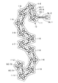
十二面体は図3に示す展開図形態の単位面で形成される。十二面体の展開図には五角形の配列についていくつかの種類が在るが、直線状に最も近いものとしてほぼS字状の展開図、すなわち、両端の五角形は一辺のみで、他の五角形は二辺において、それぞれ隣接する五角形と接合する図3の展開図が、合計72個のボイスコイルを次々と、図4について述べた一筆書きパターンで直列接続することを意図した場合に採用して便宜である。 The dodecahedron is formed by a unit surface in a developed view shown in FIG. There are several types of dodecahedron developments with respect to the pentagonal arrangement, but the S-shaped development is the closest to the straight line, that is, the pentagons at both ends are only one side, and the other pentagons are The development of FIG. 3 joined to adjacent pentagons on two sides is convenient to adopt when it is intended to connect a total of 72 voice coils one after another in series with the one-stroke pattern described for FIG. It is.
ボイスコイルVC−1〜VC−72は次のように接続される。一対の信号線の一方SL−1を1番目の単位面10の振動板1−1上の第1のボイスコイルVC―1の円周方向に2分した一方の始端に接続し、第2から第6のボイスコイルVC−6の2分した一方ずつを一対の接続線CLの一方で順次接続し、第6のボイスコイルVC−6の2分した一方の終端を、1番目と2番目の単位面の振動板1−1と1−2の間の接合辺をまたぐ一対の橋絡線BLの一方を介して、2番目の振動板1−2上の第7のボイスコイルVC−7の2分した一方の始端に接続し、同様の接続を反復して2番目の振動板1−2の第7のボイスコイルVC−7から最後の12番目の振動板1−12の第71のボイスコイルVC−71の2分した一方の始端まで順次一対の接続線の一方で接続し、第71のボイスコイルVC−71の2分した一方の終端を、2分せずにC字状とした最後の第72のボイスコイルVC−72の一端に接続して接続を折り返させ、第72のC字状ボイスコイルVC−72の他端を第71のボイスコイルVC−71の2分した他方の始端に接続し、以後、第71から第1までのボイスコイルVC−71〜VC−1の2分した他方を、順次、一対の接続線CLの他方と一対の橋絡線BLの他方とを介して接続し、第1のボイスコイルVC−1の2分した他方の終端を、一対の信号線SLの他方に接続して、十二面の振動板1−1〜1−12の全てのボイスコイルVC−1〜VC−72を1ターンのコイルとして直列に接続することとなる。図3の展開図はこのように全12個の単位面10が含む全72個のボイスコイルを直列に接続した十二面の振動板を示す。
The voice coils VC-1 to VC-72 are connected as follows. One SL-1 of the pair of signal lines is connected to one start end of the first voice coil VC-1 divided into two in the circumferential direction on the diaphragm 1-1 of the
十二面のボイスコイルVC−1〜VC−72は、図3の展開図のパターンをもって例えばPIフィルムでなる振動板表面にプリント配線され、十二連のコイル一体型で全面駆動型の振動板1−1〜1−12が形成され、図5の分解拡大断面図に示す各単位面10の構成をもって平板状の磁気回路MCと組み合わされ、各単位面10において6個の円形ボイスコイルVCと6個の環状磁気ギャップMGが、図4(C)について述べたようにそれぞれ同心状に対峙する。
The twelve-side voice coils VC-1 to VC-72 are printed and wired on the surface of the diaphragm made of, for example, a PI film with the pattern shown in the developed view of FIG. 1-1 to 1-12 are formed and combined with a flat magnetic circuit MC having the structure of each
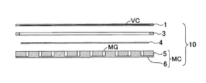
平板型の磁気回路MCは内磁型または外磁型のいずれでも良く、各正五角形単位面10の中心と中心及び各頂角の中間点とに配置した6個の円盤状の磁心又はセンターポール5と、これらの各々を同心に収容する6個の丸穴を有するヨーク板又は磁石板6とで6個の環状の磁気ギャップMGが形成される。図5では6個のボイスコイルVCと6個の磁気ギャップMGは、いずれも直線状に展開して示される。磁気ギャップMGの開口側に、望ましくは例えば不織布4を当接させ、五角形の各縁辺にフレーム3を載置し、その上面に、ボイスコイルVCを担持する振動板1を貼り付けて、単位面10が形成される。単位面10の各辺の側面は、振動板1側を表面としてその延長戦に対し116.6度の角度で面取りされ、十二面体の作成を容易にする。五角形の単位面10の一辺の長さを20mm前後、磁気ギャップの径を8.8〜6.5mm、磁気回路の高さを2mm程度とし、振動板の振幅を加えて全高を2.5mm程度とするが、更に小型にすることも可能である。磁気ギャップの径を更に小型にすれば、各単位面に対するスピーカユニットの数、つまり駆動点数を増やすこともできる。
The flat magnetic circuit MC may be either an internal magnetic type or an external magnetic type. Six disk-shaped magnetic cores or center poles arranged at the center and the center of each regular
なお、単位面10として磁気回路MCとフレーム3のみを一体化したもので十二面体を作成した後、その表面に図3の展開図の状態の振動板を貼り付けても良い。また、十二面体の展開図パターンは図3のものに限定されることなく、他の類似或いは近似パターンも採用し得る。要は、隣接単位面間の連接辺をまたぐ橋絡線を介して全十二面のボイスコイルを一筆書きで直列接続し、なお容易に十二面体に組み立て得るパターンであればよい。
In addition, after the dodecahedron is formed by integrating only the magnetic circuit MC and the frame 3 as the
10 単位面
VC ボイスコイル
VC−1〜VC−72 第1のボイスコイル〜第72のボイスコイル
CL 接続線
BL 橋絡線
SL−1 信号線
SL−2 信号線
MG 磁気ギャップ
MC 磁気回路
1 振動板
1−1〜1−12 1番目の振動板〜12番目の振動板
3 フレーム
4 不織布
5 磁心又はセンターポール
6 ヨーク板又は磁石板
10 Unit surface VC Voice coil VC-1 to VC-72 First voice coil to 72nd voice coil CL Connection line BL Bridge line SL-1 Signal line SL-2 Signal line MG Magnetic gap MC
Claims (5)
The diaphragm carrying at least the voice coil is connected to two unit sides other than the first and twelfth unit surfaces connected to the adjacent unit surface only on one side in the unfolded state of all unit surfaces. However, one of the pair of signal lines is connected to one start end of the first unit surface divided into two in the circumferential direction of the first voice coil, and thereafter one of the second to sixth voice coils divided into two. Are sequentially connected to one of the pair of connection lines, and one end of the sixth voice coil divided into two is connected via one of the pair of bridge lines straddling the connecting side between the first and second unit surfaces. Connected to the start end of one half of the seventh voice coil of the second unit surface, and similarly, 2 of the seventh voice coil of the 12th unit surface from the seventh voice coil of the second unit surface. Connect sequentially to one of the pair of connecting lines until one of the divided ends, One end of the 71 voice coil divided into two ends was connected to one end of a C-shaped 72nd voice coil to fold back the connection, and the other end of the 72nd voice coil was divided into 2nd half of the 71st voice coil The first voice is connected to the other end of the first, and then the other half of the 71st to 1st voice coils are sequentially connected via the other of the pair of connection lines and the other of the pair of bridge lines. 3. The omnidirectional speaker according to claim 2, wherein the other end of the coil divided into two is connected to the other of the pair of signal lines to form a one-stroke pattern.
Priority Applications (1)
| Application Number | Priority Date | Filing Date | Title |
|---|---|---|---|
| JP2009158463A JP5213802B2 (en) | 2009-07-03 | 2009-07-03 | Omnidirectional speaker |
Applications Claiming Priority (1)
| Application Number | Priority Date | Filing Date | Title |
|---|---|---|---|
| JP2009158463A JP5213802B2 (en) | 2009-07-03 | 2009-07-03 | Omnidirectional speaker |
Publications (2)
| Publication Number | Publication Date |
|---|---|
| JP2011015249A JP2011015249A (en) | 2011-01-20 |
| JP5213802B2 true JP5213802B2 (en) | 2013-06-19 |
Family
ID=43593669
Family Applications (1)
| Application Number | Title | Priority Date | Filing Date |
|---|---|---|---|
| JP2009158463A Active JP5213802B2 (en) | 2009-07-03 | 2009-07-03 | Omnidirectional speaker |
Country Status (1)
| Country | Link |
|---|---|
| JP (1) | JP5213802B2 (en) |
Cited By (2)
| Publication number | Priority date | Publication date | Assignee | Title |
|---|---|---|---|---|
| US10701477B2 (en) | 2018-03-27 | 2020-06-30 | Sony Corporation | Loudspeaker, acoustic waveguide, and method |
| US11012788B2 (en) | 2018-03-27 | 2021-05-18 | Sony Corporation | Loudspeaker system |
Family Cites Families (3)
| Publication number | Priority date | Publication date | Assignee | Title |
|---|---|---|---|---|
| JP2004297148A (en) * | 2003-03-25 | 2004-10-21 | Takenaka Komuten Co Ltd | Small-sized speaker for acoustic reduced scale model experiment |
| JP2005027020A (en) * | 2003-07-02 | 2005-01-27 | Fps:Kk | Speaker module and sr speaker system |
| JP4963106B2 (en) * | 2007-12-12 | 2012-06-27 | フォスター電機株式会社 | Circular flat speaker |
-
2009
- 2009-07-03 JP JP2009158463A patent/JP5213802B2/en active Active
Cited By (2)
| Publication number | Priority date | Publication date | Assignee | Title |
|---|---|---|---|---|
| US10701477B2 (en) | 2018-03-27 | 2020-06-30 | Sony Corporation | Loudspeaker, acoustic waveguide, and method |
| US11012788B2 (en) | 2018-03-27 | 2021-05-18 | Sony Corporation | Loudspeaker system |
Also Published As
| Publication number | Publication date |
|---|---|
| JP2011015249A (en) | 2011-01-20 |
Similar Documents
| Publication | Publication Date | Title |
|---|---|---|
| JP7377877B2 (en) | Multi-range speaker containing multiple diaphragms | |
| US7835536B2 (en) | Electro-acoustic transducer with multi-faced diaphragm assembly | |
| US7787645B2 (en) | Loudspeaker-transducer array | |
| JP5181034B2 (en) | Planar acoustic transducer | |
| JPWO2009063905A1 (en) | Piezoelectric acoustic element and electronic device | |
| KR100537249B1 (en) | Loudspeaker | |
| JP5213802B2 (en) | Omnidirectional speaker | |
| JP2002078079A (en) | Electroacoustic transducer | |
| WO2020057655A1 (en) | Horn structure and magnetic circuit system thereof | |
| JP2008131373A (en) | Electromagnetic transducer and speaker device | |
| JPS61253996A (en) | Parametric speaker | |
| KR101991630B1 (en) | Omnidirectional full range speaker | |
| JP2011250063A (en) | Thin whole surface drive speaker | |
| JP2004356868A (en) | Speaker | |
| CN112449288B (en) | Flexible circuit board, speaker and electronic equipment | |
| JP4193041B2 (en) | Three-dimensional intensity probe, three-dimensional sound source direction detection device and three-dimensional sound source direction facing control device using the probe | |
| JP2011151599A (en) | Low profile multiway speaker | |
| TWI665921B (en) | Electromagnetic transducer | |
| JP4964010B2 (en) | Electromagnetic transducer | |
| CN111556404A (en) | Loudspeaker | |
| Beranek | Loudspeakers and microphones | |
| CN212086467U (en) | Loudspeaker | |
| CN209949405U (en) | Moving coil flat plate composite electroacoustic transducer | |
| JP4964011B2 (en) | Electromagnetic transducer | |
| CN209949430U (en) | Moving coil flat plate composite electroacoustic transducer |
Legal Events
| Date | Code | Title | Description |
|---|---|---|---|
| A621 | Written request for application examination |
Free format text: JAPANESE INTERMEDIATE CODE: A621 Effective date: 20120607 |
|
| A977 | Report on retrieval |
Free format text: JAPANESE INTERMEDIATE CODE: A971007 Effective date: 20130212 |
|
| TRDD | Decision of grant or rejection written | ||
| A01 | Written decision to grant a patent or to grant a registration (utility model) |
Free format text: JAPANESE INTERMEDIATE CODE: A01 Effective date: 20130226 |
|
| A61 | First payment of annual fees (during grant procedure) |
Free format text: JAPANESE INTERMEDIATE CODE: A61 Effective date: 20130226 |
|
| R150 | Certificate of patent or registration of utility model |
Free format text: JAPANESE INTERMEDIATE CODE: R150 Ref document number: 5213802 Country of ref document: JP Free format text: JAPANESE INTERMEDIATE CODE: R150 |
|
| FPAY | Renewal fee payment (event date is renewal date of database) |
Free format text: PAYMENT UNTIL: 20160308 Year of fee payment: 3 |
|
| S531 | Written request for registration of change of domicile |
Free format text: JAPANESE INTERMEDIATE CODE: R313531 |
|
| R350 | Written notification of registration of transfer |
Free format text: JAPANESE INTERMEDIATE CODE: R350 |
|
| R250 | Receipt of annual fees |
Free format text: JAPANESE INTERMEDIATE CODE: R250 |
|
| R250 | Receipt of annual fees |
Free format text: JAPANESE INTERMEDIATE CODE: R250 |
|
| R250 | Receipt of annual fees |
Free format text: JAPANESE INTERMEDIATE CODE: R250 |
|
| R250 | Receipt of annual fees |
Free format text: JAPANESE INTERMEDIATE CODE: R250 |
|
| R250 | Receipt of annual fees |
Free format text: JAPANESE INTERMEDIATE CODE: R250 |
|
| R250 | Receipt of annual fees |
Free format text: JAPANESE INTERMEDIATE CODE: R250 |
|
| R250 | Receipt of annual fees |
Free format text: JAPANESE INTERMEDIATE CODE: R250 |
|
| R250 | Receipt of annual fees |
Free format text: JAPANESE INTERMEDIATE CODE: R250 |
|
| R250 | Receipt of annual fees |
Free format text: JAPANESE INTERMEDIATE CODE: R250 |