JP5212794B2 - Cylinder device and stabilizer device using the same. - Google Patents
Cylinder device and stabilizer device using the same. Download PDFInfo
- Publication number
- JP5212794B2 JP5212794B2 JP2008116214A JP2008116214A JP5212794B2 JP 5212794 B2 JP5212794 B2 JP 5212794B2 JP 2008116214 A JP2008116214 A JP 2008116214A JP 2008116214 A JP2008116214 A JP 2008116214A JP 5212794 B2 JP5212794 B2 JP 5212794B2
- Authority
- JP
- Japan
- Prior art keywords
- cylinder
- valve
- chamber
- reservoir
- piston
- Prior art date
- Legal status (The legal status is an assumption and is not a legal conclusion. Google has not performed a legal analysis and makes no representation as to the accuracy of the status listed.)
- Expired - Fee Related
Links
Images


Classifications
-
- B—PERFORMING OPERATIONS; TRANSPORTING
- B60—VEHICLES IN GENERAL
- B60G—VEHICLE SUSPENSION ARRANGEMENTS
- B60G21/00—Interconnection systems for two or more resiliently-suspended wheels, e.g. for stabilising a vehicle body with respect to acceleration, deceleration or centrifugal forces
- B60G21/02—Interconnection systems for two or more resiliently-suspended wheels, e.g. for stabilising a vehicle body with respect to acceleration, deceleration or centrifugal forces permanently interconnected
- B60G21/04—Interconnection systems for two or more resiliently-suspended wheels, e.g. for stabilising a vehicle body with respect to acceleration, deceleration or centrifugal forces permanently interconnected mechanically
- B60G21/05—Interconnection systems for two or more resiliently-suspended wheels, e.g. for stabilising a vehicle body with respect to acceleration, deceleration or centrifugal forces permanently interconnected mechanically between wheels on the same axle but on different sides of the vehicle, i.e. the left and right wheel suspensions being interconnected
- B60G21/055—Stabiliser bars
- B60G21/0551—Mounting means therefor
- B60G21/0553—Mounting means therefor adjustable
- B60G21/0556—Mounting means therefor adjustable including a releasable coupling
-
- F—MECHANICAL ENGINEERING; LIGHTING; HEATING; WEAPONS; BLASTING
- F16—ENGINEERING ELEMENTS AND UNITS; GENERAL MEASURES FOR PRODUCING AND MAINTAINING EFFECTIVE FUNCTIONING OF MACHINES OR INSTALLATIONS; THERMAL INSULATION IN GENERAL
- F16F—SPRINGS; SHOCK-ABSORBERS; MEANS FOR DAMPING VIBRATION
- F16F9/00—Springs, vibration-dampers, shock-absorbers, or similarly-constructed movement-dampers using a fluid or the equivalent as damping medium
- F16F9/32—Details
- F16F9/44—Means on or in the damper for manual or non-automatic adjustment; such means combined with temperature correction
- F16F9/46—Means on or in the damper for manual or non-automatic adjustment; such means combined with temperature correction allowing control from a distance, i.e. location of means for control input being remote from site of valves, e.g. on damper external wall
-
- B—PERFORMING OPERATIONS; TRANSPORTING
- B60—VEHICLES IN GENERAL
- B60G—VEHICLE SUSPENSION ARRANGEMENTS
- B60G2200/00—Indexing codes relating to suspension types
- B60G2200/10—Independent suspensions
- B60G2200/14—Independent suspensions with lateral arms
-
- B—PERFORMING OPERATIONS; TRANSPORTING
- B60—VEHICLES IN GENERAL
- B60G—VEHICLE SUSPENSION ARRANGEMENTS
- B60G2202/00—Indexing codes relating to the type of spring, damper or actuator
- B60G2202/10—Type of spring
- B60G2202/13—Torsion spring
- B60G2202/135—Stabiliser bar and/or tube
-
- B—PERFORMING OPERATIONS; TRANSPORTING
- B60—VEHICLES IN GENERAL
- B60G—VEHICLE SUSPENSION ARRANGEMENTS
- B60G2202/00—Indexing codes relating to the type of spring, damper or actuator
- B60G2202/30—Spring/Damper and/or actuator Units
- B60G2202/32—The spring being in series with the damper and/or actuator
-
- B—PERFORMING OPERATIONS; TRANSPORTING
- B60—VEHICLES IN GENERAL
- B60G—VEHICLE SUSPENSION ARRANGEMENTS
- B60G2204/00—Indexing codes related to suspensions per se or to auxiliary parts
- B60G2204/10—Mounting of suspension elements
- B60G2204/12—Mounting of springs or dampers
- B60G2204/122—Mounting of torsion springs
- B60G2204/1224—End mounts of stabiliser on wheel suspension
-
- B—PERFORMING OPERATIONS; TRANSPORTING
- B60—VEHICLES IN GENERAL
- B60G—VEHICLE SUSPENSION ARRANGEMENTS
- B60G2204/00—Indexing codes related to suspensions per se or to auxiliary parts
- B60G2204/40—Auxiliary suspension parts; Adjustment of suspensions
- B60G2204/46—Means for locking the suspension
-
- B—PERFORMING OPERATIONS; TRANSPORTING
- B60—VEHICLES IN GENERAL
- B60G—VEHICLE SUSPENSION ARRANGEMENTS
- B60G2204/00—Indexing codes related to suspensions per se or to auxiliary parts
- B60G2204/62—Adjustable continuously, e.g. during driving
-
- B—PERFORMING OPERATIONS; TRANSPORTING
- B60—VEHICLES IN GENERAL
- B60G—VEHICLE SUSPENSION ARRANGEMENTS
- B60G2206/00—Indexing codes related to the manufacturing of suspensions: constructional features, the materials used, procedures or tools
- B60G2206/01—Constructional features of suspension elements, e.g. arms, dampers, springs
- B60G2206/40—Constructional features of dampers and/or springs
- B60G2206/41—Dampers
-
- B—PERFORMING OPERATIONS; TRANSPORTING
- B60—VEHICLES IN GENERAL
- B60G—VEHICLE SUSPENSION ARRANGEMENTS
- B60G2400/00—Indexing codes relating to detected, measured or calculated conditions or factors
- B60G2400/10—Acceleration; Deceleration
- B60G2400/104—Acceleration; Deceleration lateral or transversal with regard to vehicle
-
- B—PERFORMING OPERATIONS; TRANSPORTING
- B60—VEHICLES IN GENERAL
- B60G—VEHICLE SUSPENSION ARRANGEMENTS
- B60G2400/00—Indexing codes relating to detected, measured or calculated conditions or factors
- B60G2400/40—Steering conditions
-
- B—PERFORMING OPERATIONS; TRANSPORTING
- B60—VEHICLES IN GENERAL
- B60G—VEHICLE SUSPENSION ARRANGEMENTS
- B60G2500/00—Indexing codes relating to the regulated action or device
- B60G2500/10—Damping action or damper
- B60G2500/11—Damping valves
-
- B—PERFORMING OPERATIONS; TRANSPORTING
- B60—VEHICLES IN GENERAL
- B60G—VEHICLE SUSPENSION ARRANGEMENTS
- B60G2600/00—Indexing codes relating to particular elements, systems or processes used on suspension systems or suspension control systems
- B60G2600/22—Magnetic elements
- B60G2600/26—Electromagnets; Solenoids
-
- B—PERFORMING OPERATIONS; TRANSPORTING
- B60—VEHICLES IN GENERAL
- B60G—VEHICLE SUSPENSION ARRANGEMENTS
- B60G2800/00—Indexing codes relating to the type of movement or to the condition of the vehicle and to the end result to be achieved by the control action
- B60G2800/01—Attitude or posture control
- B60G2800/012—Rolling condition
-
- B—PERFORMING OPERATIONS; TRANSPORTING
- B60—VEHICLES IN GENERAL
- B60G—VEHICLE SUSPENSION ARRANGEMENTS
- B60G2800/00—Indexing codes relating to the type of movement or to the condition of the vehicle and to the end result to be achieved by the control action
- B60G2800/90—System Controller type
- B60G2800/91—Suspension Control
- B60G2800/912—Attitude Control; levelling control
- B60G2800/9122—ARS - Anti-Roll System Control
Description
本発明は、ピストンロッドをロック可能なシリンダ装置及びこれを用いた車両のロール制御を行なうためのスタビライザ装置に関するものある。 The present invention relates to a cylinder device capable of locking a piston rod and a stabilizer device for performing roll control of a vehicle using the cylinder device.
自動車等の車両のサスペンション装置においては、旋回時の車体のロールを抑制するためにトーションバー式のスタビライザが用いられている。トーションバー式のスタビライザは、車輪を支持する左右のサスペンションアームを車体側に回動可能に支持されたトーションバーによって互いに連結した構造であり、左右のサスペンションアームの同方向(同相)のストロークに対しては、トーションバーの回動によりバネ力を作用させず、逆方向(逆相)のストロークに対しては、トーションバーの捻りによってバネ力を作用させるようになっている。 2. Description of the Related Art A suspension device for a vehicle such as an automobile uses a torsion bar type stabilizer to suppress the roll of the vehicle body when turning. The torsion bar type stabilizer is a structure in which the left and right suspension arms that support the wheels are connected to each other by a torsion bar that is rotatably supported on the vehicle body side. Therefore, the spring force is not applied by the rotation of the torsion bar, and the spring force is applied to the stroke in the reverse direction (reverse phase) by twisting the torsion bar.
これにより、車両の直進時には、トーションバーのバネ力を作用させず、路面からの振動入力を吸収し易くし、旋回時にはトーションバーの捻りによるバネ力によってロール剛性を高めて操縦安定性を高めることができる。 As a result, the spring force of the torsion bar is not applied when the vehicle is traveling straight, making it easy to absorb vibration input from the road surface, and when turning, the roll force is increased by the spring force of the torsion bar torsion and steering stability is improved. Can do.
また、例えば特許文献1に記載されているように、トーションバーと一方のサスペンションアームとの間に油圧シリンダを連結し、油圧シリンダの作動ロッドをロック、ロック解除することにより、トーションバーとサスペンションアームとの間のバネ力の伝達をオン、オフすることができるようにしたスタビライザ装置が知られている。これにより、車両の走行状態応じて適宜スタビライザの作動をオン、オフすることができ、乗り心地及び操縦安定性を高めることができる。
このスタビライザ装置の油圧シリンダは、油液が封入されたシリンダ内にピストンを摺動可能に嵌装し、ピストンに連結されたピストンロッドをシリンダの両端側から外部に延出させ、更に、ピストンによって画成された2つのシリンダ室を連通する連通路に開閉弁を設けた構造となっている。これにより、開閉弁によって2つのシリンダ室間を遮断、連通することにより、ピストンすなわちピストンロッドの移動をロック、ロック解除することができる。 The hydraulic cylinder of this stabilizer device has a piston slidably fitted in a cylinder filled with an oil liquid, and piston rods connected to the piston extend from both ends of the cylinder to the outside. An open / close valve is provided in a communication path that connects two defined cylinder chambers. Accordingly, the movement of the piston, that is, the piston rod can be locked and unlocked by shutting off and communicating between the two cylinder chambers by the opening / closing valve.
このように、シリンダの両端部からピストンロッドを延出させた構造(両ロッド構造)を採っているため、ピストンロッドの移動に対するシリンダの容積変化がないので、リザーバを設ける必要がなく、また、ロック時において、ガスの圧縮、膨張によるピストンロッドのロック不良の問題を生じることがない。 Thus, since the piston rod is extended from both ends of the cylinder (both rod structure), there is no change in the volume of the cylinder with respect to the movement of the piston rod, so there is no need to provide a reservoir, At the time of locking, there is no problem of poor piston rod locking due to gas compression and expansion.
しかしながら、特許文献1に記載された従来のスタビライザ装置では、次のような問題がある。すなわち、リザーバを備えていないため、油液の熱膨張に対する温度補償が困難であり、また、両ロッド構造であるため、油圧シリンダの全長が長くなってしまう。
However, the conventional stabilizer device described in
本発明は、上記の点に鑑みてなされたものであり、シリンダの一端部からピストンロッドが延出された片ロッド構造で、ピストンロッドのロックを確実に行なうことができ、かつ、温度補償が可能なシリンダ装置及びこれを用いたスタビライザ装置を提供することを目的とする。 The present invention has been made in view of the above points, and has a single-rod structure in which a piston rod is extended from one end of a cylinder. The piston rod can be reliably locked, and temperature compensation can be performed. It is an object of the present invention to provide a possible cylinder device and a stabilizer device using the same.
上記の課題を解決するために、本発明に係るシリンダ装置は、油液が封入されたシリンダと、前記シリンダ内に摺動可能に嵌装されて該シリンダ内を第1室と第2室とに画成するピストンと、一端が前記ピストンに連結され、他端が前記第1室を通って外部へ延出されたピストンロッドと、前記シリンダの外周に設けられて該シリンダとの間に油液及びガスが封入されたリザーバを形成する外筒と、前記第2室と前記リザーバとを画成するベースバルブと、前記ピストンに設けられて前記第2室側から前記第1室側への油液の流通のみを許容する第1逆止弁と、前記ベースバルブに設けられて前記リザーバ側から前記第2室側への油液の流通のみを許容する第2逆止弁と、前記第1室から前記リザーバへの流れを許す唯一の流路と、該流路を開閉し、閉弁時に油液の流れを阻止する電磁開閉弁とからなり、該電磁開閉弁を閉弁することで、前記シリンダに対し前記ピストンロッドを固定可能にしたことを特徴とする。 In order to solve the above-described problems, a cylinder device according to the present invention includes a cylinder in which oil is sealed, a slidably fitted in the cylinder, and a first chamber and a second chamber in the cylinder. Between the piston, one end connected to the piston, the other end extending to the outside through the first chamber, and an outer periphery of the cylinder. an outer cylinder forming a reservoir fluid and gas is sealed, a base valve which defines the said and said second chamber reservoir, from the second chamber side is provided on the piston to the first chamber side a first check valve that allows only the flow of hydraulic fluid, and a second check valve that allows only the flow of hydraulic fluid to the second chamber side from said reservoir side provided in the base valve, the first A single flow path allowing flow from one chamber to the reservoir; and Closed, consists of a solenoid valve for preventing the flow of hydraulic fluid when the valve is closed, by closing the solenoid valve, characterized in that to said cylinder and to be fixed to the piston rod.
本発明に係るシリンダ装置によれば、開閉弁によってシリンダ側からリザーバ側への流路を遮断することにより、油液の非圧縮性によってピストンロッドを確実にロックすることができ、また、リザーバのガスの圧縮膨張によって、油液の熱膨張に対する温度補償を行なうことができる。 According to the cylinder device of the present invention, the piston rod can be reliably locked by the incompressibility of the oil liquid by blocking the flow path from the cylinder side to the reservoir side by the on-off valve, The temperature compensation for the thermal expansion of the oil liquid can be performed by compressing and expanding the gas.
以下、本発明の一実施形態を図面に基づいて詳細に説明する。
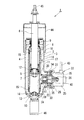
本実施形態に係るシリンダ装置について、図1及び図2を参照して説明する。図1に示すように、シリンダ装置1は、シリンダ2の外周に外筒3を設けた二重筒構造となっており、シリンダ2と外筒3との間にリザーバ4が形成されている。シリンダ2内には、ピストン5が摺動可能に嵌装されており、このピストン5によってシリンダ2内がシリンダ上室2A(第1室)とシリンダ下室2B(第2室)との2室に画成されている。ピストン5には、ピストンロッド6の一端がナット7によって連結されており、ピストンロッド6の他端側は、シリンダ上室2Aを通り、シリンダ2及び外筒3の上端部に装着されたロッドガイド8およびオイルシール9に挿通されて、シリンダ2の一端部から外部へ延出されている。シリンダ2の下端部には、シリンダ下室2Bとリザーバ4とを区画するベースバルブ10が設けられている。
Hereinafter, an embodiment of the present invention will be described in detail with reference to the drawings.
A cylinder device according to this embodiment will be described with reference to FIGS. 1 and 2. As shown in FIG. 1, the
ピストン5には、シリンダ上下室2A、2B間を連通させる油路11が設けられており、油路11には、シリンダ下室2B側からシリンダ上室2A側への油液の流通のみを許容する逆止弁12が設けられている。また、ベースバルブ10には、シリンダ下室2Bとリザーバ4とを連通させる油路13が設けられており、油路13には、リザーバ4側からシリンダ下室2B側への油液の流通のみを許容する逆止弁14が設けられている。そして、シリンダ2内には油液が封入されており、リザーバ4内には油液及びガスが封入されている。
The
シリンダ2には、上下両端部にシール部材15を介してセパレータチューブ16が外嵌されており、シリンダ2とセパレータチューブ16との間に環状油路17が形成されている。環状油路17は、シリンダ2の上端部付近の側壁に設けられた油路18によってシリンダ上室2Aに連通されている。セパレータチューブ16の下部側壁には、開口19(第1開口)が設けられている。また、外筒3の下部側壁には、開口19に対向させて、これよりも大径の開口20(第2開口)が開口19と同心に設けられており、開口20には、円筒状のケース21が溶接等によって取付けられている。そして、ケース21に、環状油路17とリザーバ4との間の流路を開閉する電磁開閉弁22(開閉弁)が取付けられている。
A
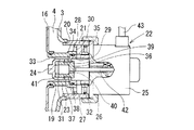
電磁開閉弁22について、図2を参照して説明する。図2に示すように、ケース21内には、通路部材23及びガイド部材24が挿入され、ケース21の開口部にソレノイドアクチュエータ25がナット26によって取り付けられて、通路部材23及びガイド部材24を固定している。通路部材23は、一端部外周にフランジ部27を有する略円筒状で、円筒状の他端部がセパレータチューブ16の開口19に液密的に挿入され、フランジ部27がケース21に嵌合されている。通路部材23は、フランジ部27がケース21の内壁に取付けられたストッパ28に当接することによって、その軸方向に位置決めされている。通路部材23は、フランジ部27側の端部の内周が拡径されて拡径部29が形成されており、また、フランジ部27に、その軸方向に沿って油路30が貫通されている。
The electromagnetic on-off
ガイド部材24は、小径部31(スリーブ)及び大径部32を有し、小径部31側の端部に底部を有する段付円筒状に形成されている。そして、小径部31が通路部材23に隙間をもって挿入されて、通路部材23との間に、環状油路17に連通する環状の油室33が形成されている。また、大径部32が通路部材23の拡径部29に嵌合されて、その端部(段部)に当接して、ガイド部材24が軸方向に位置決めされている。ガイド部材24の小径部31の側壁には、油室33に連通するポート34が貫通されている。また、ガイド部材24の大径部32の側壁には、ポート35が貫通されており、ポート35は、通路部材23のフランジ部27に設けられた油路30を介してリザーバ4に接続されている。
The
ガイド部材24の小径部31内には、略有底円筒状のバルブ部材36(弁体)が摺動可能に嵌合されている。バルブ部材36の側壁には、ガイド部材24のポート21に対向する外周溝37が形成されている。バルブ部材36の底部側の端部は、ガイド部材24の小径部31の内径よりも大径に形成され、外周溝37の大径側の端部に形成されたテーパ状のシート面38がガイド部材24の小径部31の内周側の端縁部に形成されたシート部39(段部)に当接(着座)するようになっている。バルブ部材36の底部には、圧力バランス通路40が貫通されている。
A substantially bottomed cylindrical valve member 36 (valve element) is slidably fitted in the
バルブ部材36の底部の内側とガイド部材24の底部との間には、バネ41(圧縮バネ)が介装され、また、バルブ部材36の底部の外側には、ソレノイドアクチュエータ25の作動ロッド42が当接している。ソレノイドアクチュエータ25は、リード線43によってコイル(図示せず)に通電することにより、推力を発生させて作動ロッド42を伸長させるようになっている。そして、バルブ部材36は、通常は、バネ41のバネ力によってソレノイドアクチュエータ25側へ移動してシート面38がシート部39から離間して、ポート34、35間を連通させており、ソレノイドアクチュエータ25の作動ロッド42によってバネ41のバネ力に抗してガイド部材24の底部側に移動させて、シート面38をシート部39に当接(着座)させることにより、ポート34、35間を遮断する。
A spring 41 (compression spring) is interposed between the inside of the bottom of the
ピストンロッド6には、有底円筒状のダストカバー44が取付けられ、更に、先端部に取付部45が設けられており、また、外筒3の下端部には、取付アイ46が設けられている。
The
以上のように構成したシリンダ装置1の作用について次に説明する。
シリンダ装置1は、ピストンロッド6が伸長する際には、シリンダ2内のピストン5の移動によって、ピストン5の逆止弁12が閉じ、シリンダ上室2A側の油液が加圧されて、油路18及び環状油路17を通って電磁開閉弁22の環状の油室33へ流れる。さらに、環状の油室33から、ポート34、ポート35及び油路30を通ってリザーバ4へ流れる。このとき、ピストン5が移動した分の油液がリザーバ4からベースバルブ10の逆止弁14を開いてシリンダ下室2Bへ流入し、ピストンロッド6がシリンダ2から退出した分だけリザーバ4のガスが膨張することによってシリンダ2内の容積変化を補償する。
Next, the operation of the
In the
また、ピストンロッド6が短縮する際には、シリンダ2内のピストン5の移動によって、ピストン5の逆止弁12が開き、ベースバルブ10の油路15の逆止弁14が閉じて、ピストン下室2Bの油液がシリンダ上室2Aへ流入し、ピストンロッド6がシリンダ2内に侵入した分の油液がシリンダ上室2Aから、上記ピストンロッド6が伸長する際と同様の経路を通ってリザーバ4へ流れる。このとき、ピストンロッド6がシリンダ2内に侵入した分だけリザーバ4のガスが圧縮されることにより、シリンダ2内の容積変化を補償する。
When the
ソレノイドアクチュエータ25の非通電時には、バネ41の付勢力によってバルブ部材36がソレノイドアクチュエータ25側に移動しており、シート面38がシート部39から離間してポート間34、35間が連通され、シリンダ上室2A側からリザーバ4側への油液の流通を許容するので、ピストンロッド6を自由に伸縮させることができる。
When the
通電によりソレノイドアクチュエータ25を作動させ、バルブ部材36をバネ41の付勢力に抗して移動させ、シート面38をシート部39に当接させて、ポート34、35間を遮断すると、シリンダ上室2A側からリザーバ4側への油液の流れが阻止されるので、ピストンロッド6は、伸縮いずれの方向に対してもロックされる。
When the
このとき、ピストンロッド6を伸縮いずれの方向に移動させようとする力も、シリンダ2から電磁開閉弁22までの流路に満たされた油液に対する圧縮力として作用するので、油液の非圧縮性によってピストン6の移動を確実にロックすることができる。
At this time, the force to move the
電磁開閉弁22では、閉弁時にポート34から弁体36に作用する油液の圧力が弁体36の外周溝37の両端部に作用するが、この両端部の受圧面積が等しくなっているため、圧力がバランスして、弁体36を移動させようとする力が生じないので、バネ41のバネ力及びソレノイドアクチュエータ25の推力が小さくてすみ、小型化及び省電力化を図ることができる。なお、本実施形態では、電磁開閉弁22は通電時に閉弁する、常開弁として構成されているが、通電時に開弁する常閉弁としてもよい。電磁開閉弁のフェイル時に操縦安定性を優先する場合は、このような構成をとることができる。
In the electromagnetic on-off
弁体36は、テーパ状のシート面38をシート部39(段付部)に当接させることによって流路を遮断するので、油液の漏れを最小限に抑えることができ、ピストンロッド6を確実にロックすることができる。なお、本実施形態では、電磁開閉弁22の閉弁時は、漏れが無いように設定されているが、スタビライザ装置に必要なロック力を得ることができる範囲であれば、漏れがあるように設定することもできる。漏れ量の許容値は、車種や乗り味あるいは温度補償などの目的に応じて異なるが、例えば、オリフィス径φ0.1から0.95に相当する漏れ量とすることができる。
Since the
また、リザーバ4を備えているので、ピストンロッド6の伸縮に伴なうシリンダ2内の容積変化及び油液の熱膨張による体積変化をリザーバ内のガスの圧縮、膨張によって補償することができる。
Further, since the
次に、上記実施形態の変形例について、図3乃至図5を参照して説明する。なお、以下の説明において、図1及び図2に示すものに対して、同様の部分には同一の符号を付して異なる部分についてのみ詳細に説明する。 Next, a modification of the above embodiment will be described with reference to FIGS. In the following description, like parts shown in FIGS. 1 and 2 are given like reference numerals, and only different parts will be described in detail.
図3に示す変形例では、ガイド部材24の小径部31の内周部は、弁体36を案内する底部側(内径D1)に対して、大径部32側が拡径されて拡径部(内径D2>D1)が形成されており、これにより、ポート34の油液の圧力に対する弁体36の外周溝37の両端部の受圧面積は、シート面38側が大きくなっている。
In the modification shown in FIG. 3, the inner diameter portion of the
このように構成したことにより、弁体36の閉弁時にポート34が加圧されると、外周溝37の両端部の受圧面積差によって、弁体36に開弁方向の力が生じ、この力がソレノイドアクチュエータ25の推力に打勝つと弁体36が開弁する。これにより、シリンダ2内の圧力が所定圧力に達したとき、電磁開閉弁22が開弁して、その圧力をリザーバ4へリリーフすることがき、シリンダ2内の過度の圧力の上昇を防止することできる。
With this configuration, when the
図4及び図5に示す変形例では、図4に示すように、ピストン5には、シリンダ上下室2A、2B間を連通する伸び側リリーフ通路47が設けられ、伸び側リリーフ通路47には、シリンダ上室2Aの圧力が所定圧力に達すると、開弁してその圧力をシリンダ下室2Bへリリーフする常閉の伸び側リリーフ弁48(第1リリーフ弁)が設けられている。
In the modification shown in FIGS. 4 and 5, as shown in FIG. 4, the
また、図5に示すように、ベースバルブ10には、シリンダ下室2Bとリザーバ4とを連通する縮み側リリーフ通路49が設けられ、縮み側リリーフ通路49には、シリンダ下室2Bの圧力が所定圧力に達すると、開弁してその圧力をリザーバ4へリリーフする常閉の縮み側リリーフ50(第2リリーフ弁)が設けられている。
As shown in FIG. 5, the
このように構成したことにより、ピストンロッド6を伸長させようとする力によってシリンダ上室2Aの圧力が所定圧力に達すると、ピストン5の伸び側リリーフ弁48が開いてその圧力をシリンダ下室2Bにリリーフする。また、ピストンロット6を短縮させようとする力によってシリンダ下室2Bの圧力が所定圧力に達すると、ベースバルブ10の縮み側リリーフ弁50が開いてその圧力をリザーバ4へリリーフする。これにより、シリンダ2内の圧力の過度の上昇を防止することができる。
With this configuration, when the pressure in the cylinder upper chamber 2A reaches a predetermined pressure due to the force for extending the
次に、シリンダ装置1が装着されるスタビライザ装置について、図6を参照して説明する。図6に示すように、スタビライザ装置51は、左右の車輪52、53を支持する一対のサスペンションアーム54、55(サスペンション部材)を車幅方向に延びるトーションバー56によって互いに連結した構造となっている。トーションバー56は、車体(図示せず)に対して回動可能に支持されており、一端側がリンクブラケット57を介して一方のサスペンションアーム47に連結され、また、他端側がシリンダ装置1を介して他方のサスペンションアーム55に連結されている。ここで、トーションバー56の他端側は、シリンダ装置のピストンロッド6の取付部45に連結され、シリンダ装置2の外筒3の下端部の取付アイ46がサスペンションアーム55に連結されている。
Next, a stabilizer device to which the
シリンダ装置1のソレノイドアクチュエータ25のリード線43は、コントローラ58に接続されている。コントローラ56は、加速度センサ、操舵角センサ等の車両状態を検出する各種センサ(図示せず)の検出に基づき、車両の走行状態に応じてリード線43を介してソレノイドアクチュエータ25に制御電流を出力して電磁開閉弁22の開閉を制御する。
The
このように構成したことにより、電磁制御弁22を開くと、シリンダ装置1のピストンロッド6の伸縮が許容されるので、サスペンションアーム54、55のストロークに対して、トーションバー56のバネ力が作用することがなく、トーションバー56はスタビライザとして作動しない。また、電磁制御弁22を閉じると、シリンダ装置1のピストンロッド6がロックされるので、左右のサスペンションアーム54、55がトーションバー56によって互いに連結されることになり、トーションバー56がスタビライザとして作動する。これにより、コントローラ56によって、車両の走行状態応じて適宜スタビライザの作動をオン、オフすることができ、乗り心地及び操縦安定性を高めることができる。
なお、上記実施形態では、セパレータチューブ16によって、本発明の流路を形成したが、これに限らず、リザーバ4内の電磁開閉弁22側に、油路18と通路部材23内とを連通する細いチューブを設けてもよい。
また、本発明のシリンダ装置をトーションバーの2箇所に設けてもよい。
With this configuration, when the
In the above embodiment, the flow path of the present invention is formed by the
Moreover, you may provide the cylinder apparatus of this invention in two places of a torsion bar.
1 シリンダ装置、2 シリンダ、2A シリンダ上室(第1室)、2B シリンダ下室(第2室)、3 外筒、4 リザーバ、5 ピストン、6 ピストンロッド、10 ベースバルブ、12 逆止弁(第1逆止弁)、14 逆止弁(第2逆止弁)、16 セパレータチューブ、17 環状油路、18 油路、22 電磁開閉弁(開閉弁) 1 cylinder device, 2 cylinder, 2A cylinder upper chamber (first chamber), 2B cylinder lower chamber (second chamber), 3 outer cylinder, 4 reservoir, 5 piston, 6 piston rod, 10 base valve, 12 check valve ( First check valve), 14 Check valve (second check valve), 16 Separator tube, 17 Annular oil passage, 18 Oil passage, 22 Electromagnetic on-off valve (on-off valve)
Claims (10)
前記開閉弁は、前記流路を構成するポートが側壁に設けられた円筒状のスリーブと、該スリーブに摺動可能に嵌装されて前記ポートに対向する外周溝を有する弁体とを備え、前記スリーブの端縁部に形成されたシート部に前記外周溝の一端部に形成されたシート面が離着座することによって前記ポートを開閉することを特徴とするシリンダ装置。 A cylinder filled with oil, a piston slidably fitted in the cylinder and defining the first chamber and the second chamber in the cylinder, one end connected to the piston, and the other end A piston rod extending to the outside through the first chamber, an outer cylinder provided on the outer periphery of the cylinder and forming a reservoir in which oil and gas are sealed between the cylinder and the first cylinder, A base valve that defines two chambers and the reservoir; a first check valve that is provided on the piston and that allows only fluid flow from the second chamber side to the first chamber side; and the base A second check valve provided on the valve and allowing only fluid flow from the reservoir side to the second chamber side, a flow path connecting the first chamber and the reservoir, and the flow path An open / close valve that opens and closes. And allowing fixing the piston rod,
The on-off valve includes a cylindrical sleeve provided with a port constituting the flow path on a side wall, and a valve body slidably fitted to the sleeve and having an outer circumferential groove facing the port, The cylinder device according to claim 1, wherein the port is opened and closed by a seat surface formed at one end portion of the outer circumferential groove being seated on and off from a seat portion formed at an end edge portion of the sleeve.
前記シリンダ装置は、油液が封入されたシリンダと、前記シリンダ内に摺動可能に嵌装されて該シリンダ内を第1室と第2室とに画成するピストンと、一端が前記ピストンに連結され、他端が前記第1室を通って外部へ延出されたピストンロッドと、前記シリンダの外周に設けられて該シリンダとの間に油液及びガスが封入されたリザーバを形成する外筒と、前記第2室と前記リザーバとを画成するベースバルブと、前記ピストンに設けられて前記第2室側から前記第1室側への油液の流通のみを許容する第1逆止弁と、前記ベースバルブに設けられて前記リザーバ側から前記第2室側への油液の流通のみを許容する第2逆止弁と、前記第1室から前記リザーバへの流れを許す唯一の流路と、該流路を開閉し、閉弁時に油液の流れを阻止する電磁開閉弁とを備え、該電磁開閉弁を閉弁することで、前記シリンダに対し前記ピストンロッドを固定可能であることを特徴とするスタビライザ装置。 One end of a torsion bar supported so as to be rotatable with respect to the vehicle body is connected to one of a pair of suspension members that support left and right wheels, and the other end is connected to the other of the pair of suspension members via a cylinder device. A stabilizer device,
The cylinder device includes a cylinder filled with oil, a piston slidably fitted in the cylinder and defining the inside of the cylinder into a first chamber and a second chamber, and one end connected to the piston. A piston rod that is connected and has the other end extending outside through the first chamber, and an outer portion that is provided on the outer periphery of the cylinder to form a reservoir in which oil and gas are sealed. A cylinder, a base valve that defines the second chamber and the reservoir, and a first check that is provided on the piston and allows only fluid to flow from the second chamber side to the first chamber side. A valve, a second check valve that is provided in the base valve and allows only fluid to flow from the reservoir side to the second chamber side, and the only valve that allows flow from the first chamber to the reservoir open and close the flow path, the flow path, preventing the flow of hydraulic fluid when the valve is closed And a magnetic closing valve, by closing the solenoid valve, the stabilizer and wherein the relative said cylinder is fixable to the piston rod.
前記シリンダ装置は、油液が封入されたシリンダと、前記シリンダ内に摺動可能に嵌装されて該シリンダ内を第1室と第2室とに画成するピストンと、一端が前記ピストンに連結され、他端が前記第1室を通って外部へ延出されたピストンロッドと、前記シリンダの外周に設けられて該シリンダとの間に油液及びガスが封入されたリザーバを形成する外筒と、前記第2室と前記リザーバとを画成するベースバルブと、前記外筒の内側で前記シリンダに外嵌されて前記シリンダとの間に環状油路を形成するセパレータチューブと、前記第1室と前記環状油路とを接続する油路と、前記ピストンに設けられて前記第2室側から前記第1室側への油液の流通のみを許容する第1逆止弁と、前記ベースバルブに設けられて前記リザーバ側から前記第2室側への油液の流通のみを許容する第2逆止弁と、前記環状油路から前記リザーバへの流れを許す唯一の流路と、該流路を開閉し、閉弁時に油液の流れを阻止する開閉弁とを備え、該開閉弁を閉弁することで、前記シリンダに対し前記ピストンロッドを固定可能であり、
前記セパレータチューブの側壁には、前記環状油路に連通する第1開口が設けられ、前記外筒の側壁には、前記第1開口に対向する部位に前記リザーバに連通する第2開口が設けられており、
前記開閉弁は、前記第2開口に取付けられたケース内に、前記第1開口と前記第2開口とを連通する前記流路及び該流路を開閉する弁体が配置され、更に、該弁体を駆動するソレノイドアクチュエータを備えた電磁開閉弁であり、
コントローラによって、車両の走行状態に基づいて、前記ソレノイドアクチュエータの作動を制御することを特徴とするスタビライザ装置。 One end of a torsion bar supported so as to be rotatable with respect to the vehicle body is connected to one of a pair of suspension members that support left and right wheels, and the other end is connected to the other of the pair of suspension members via a cylinder device. A stabilizer device,
The cylinder device includes a cylinder filled with oil, a piston slidably fitted in the cylinder and defining the inside of the cylinder into a first chamber and a second chamber, and one end connected to the piston. A piston rod that is connected and has the other end extending outside through the first chamber, and an outer portion that is provided on the outer periphery of the cylinder to form a reservoir in which oil and gas are sealed. A cylinder, a base valve that defines the second chamber and the reservoir, a separator tube that is externally fitted to the cylinder inside the outer cylinder to form an annular oil passage between the cylinder, An oil passage that connects one chamber and the annular oil passage, a first check valve that is provided in the piston and that allows only a fluid flow from the second chamber side to the first chamber side, The second valve is provided on the base valve from the reservoir side. A second check valve that allows only the flow of hydraulic fluid to the side, and the only flow path from the ring-shaped oil passage allowing the flow to the reservoir, to open and close the flow path, the flow of hydraulic fluid when the valve is closed An on-off valve for preventing the valve, and by closing the on-off valve, the piston rod can be fixed to the cylinder.
A side wall of the separator tube is provided with a first opening that communicates with the annular oil passage, and a side wall of the outer cylinder is provided with a second opening that communicates with the reservoir at a portion facing the first opening. And
The on-off valve has a flow passage communicating the first opening and the second opening and a valve body for opening and closing the flow passage disposed in a case attached to the second opening. An electromagnetic on-off valve equipped with a solenoid actuator that drives the body ,
A stabilizer device, wherein the operation of the solenoid actuator is controlled by a controller based on a running state of the vehicle.
Priority Applications (2)
| Application Number | Priority Date | Filing Date | Title |
|---|---|---|---|
| JP2008116214A JP5212794B2 (en) | 2008-04-25 | 2008-04-25 | Cylinder device and stabilizer device using the same. |
| US12/382,641 US7997588B2 (en) | 2008-04-25 | 2009-03-20 | Cylinder apparatus and stabilizer apparatus using the same |
Applications Claiming Priority (1)
| Application Number | Priority Date | Filing Date | Title |
|---|---|---|---|
| JP2008116214A JP5212794B2 (en) | 2008-04-25 | 2008-04-25 | Cylinder device and stabilizer device using the same. |
Publications (3)
| Publication Number | Publication Date |
|---|---|
| JP2009264515A JP2009264515A (en) | 2009-11-12 |
| JP2009264515A5 JP2009264515A5 (en) | 2011-04-28 |
| JP5212794B2 true JP5212794B2 (en) | 2013-06-19 |
Family
ID=41214229
Family Applications (1)
| Application Number | Title | Priority Date | Filing Date |
|---|---|---|---|
| JP2008116214A Expired - Fee Related JP5212794B2 (en) | 2008-04-25 | 2008-04-25 | Cylinder device and stabilizer device using the same. |
Country Status (2)
| Country | Link |
|---|---|
| US (1) | US7997588B2 (en) |
| JP (1) | JP5212794B2 (en) |
Cited By (1)
| Publication number | Priority date | Publication date | Assignee | Title |
|---|---|---|---|---|
| CN105082924A (en) * | 2015-08-24 | 2015-11-25 | 华一精密机械(昆山)有限公司 | Automobile balancing pole |
Families Citing this family (17)
| Publication number | Priority date | Publication date | Assignee | Title |
|---|---|---|---|---|
| JP5212794B2 (en) * | 2008-04-25 | 2013-06-19 | 日立オートモティブシステムズ株式会社 | Cylinder device and stabilizer device using the same. |
| US8070169B2 (en) * | 2008-07-10 | 2011-12-06 | Hyundai Motor Company | Actuator for active roll control system |
| JP5321822B2 (en) * | 2009-05-28 | 2013-10-23 | 日立オートモティブシステムズ株式会社 | Cylinder device and stabilizer device |
| WO2011025388A1 (en) * | 2009-08-24 | 2011-03-03 | Simeon Phillip George Gilbert | A self regulating fully pneumatic suspension system |
| US8498773B2 (en) * | 2010-05-20 | 2013-07-30 | GM Global Technology Operations LLC | Stability enhancing system and method for enhancing the stability of a vehicle |
| KR101231758B1 (en) * | 2010-10-05 | 2013-02-08 | 김기찬 | Actuator using oil pressure or pneumatic pressure |
| JP5961020B2 (en) * | 2012-03-21 | 2016-08-02 | Kyb株式会社 | Suspension device |
| CN103032503B (en) * | 2012-12-31 | 2014-12-24 | 江苏大学 | Semi-active suspension energy feedback device of hybrid electric vehicle |
| IT201700049536A1 (en) * | 2017-05-08 | 2018-11-08 | Piaggio & C Spa | Shock absorber with selective two-way lock, wheel unit and relative motor vehicle |
| US10981429B2 (en) * | 2017-09-29 | 2021-04-20 | Fox Factory, Inc. | Electronically controlled sway bar damping link |
| KR102063344B1 (en) * | 2018-01-11 | 2020-01-07 | 주식회사 만도 | Shock absorber for use in suspension system of vehicle |
| US10780757B2 (en) * | 2018-07-09 | 2020-09-22 | Hitachi Automtive Systems Americas, Inc. | Damper with vehicle interface adapter |
| IT201800007584A1 (en) * | 2018-07-27 | 2020-01-27 | Sistemi Sospensioni Spa | Variable damping hydraulic shock absorber, particularly for vehicle suspension. |
| US11466746B2 (en) | 2020-08-14 | 2022-10-11 | DRiV Automotive Inc. | Damper assembly |
| US11634003B2 (en) | 2020-12-17 | 2023-04-25 | Fox Factory, Inc. | Automated control system for an electronically controlled sway bar link |
| US20230271473A1 (en) * | 2021-12-20 | 2023-08-31 | Fox Factory, Inc. | Electronically controlled sway bar damping link |
| EP4269137A1 (en) * | 2022-04-26 | 2023-11-01 | Fox Factory, Inc. | System and method |
Family Cites Families (23)
| Publication number | Priority date | Publication date | Assignee | Title |
|---|---|---|---|---|
| US3559776A (en) * | 1969-06-17 | 1971-02-02 | Gen Motors Corp | Shock lockout and piston system |
| JPS58163738U (en) * | 1982-04-27 | 1983-10-31 | 株式会社昭和製作所 | Damping force adjustment device in hydraulic shock absorber |
| JPS6013744Y2 (en) * | 1983-09-26 | 1985-05-01 | カヤバ工業株式会社 | Front fork for motorcycles |
| JPH0542813A (en) * | 1991-08-12 | 1993-02-23 | Nippondenso Co Ltd | Stabilizer controller |
| JP4288430B2 (en) * | 1995-12-26 | 2009-07-01 | 株式会社日立製作所 | Damping force adjustable hydraulic shock absorber |
| DE19624898C2 (en) * | 1996-06-21 | 1998-07-02 | Mannesmann Sachs Ag | Damping valve with variable damping force |
| US5937975A (en) * | 1996-06-21 | 1999-08-17 | Fichtel & Sachs Ag | Vibration damper for a motor vehicle and a vibration damper having a damping valve with adjustable damping force for a motor vehicle |
| DE19624897C2 (en) * | 1996-06-21 | 2000-01-27 | Mannesmann Sachs Ag | Damping valve with variable damping force |
| DE19624895C1 (en) * | 1996-06-21 | 1997-12-11 | Mannesmann Sachs Ag | Vibration damper with variable steam power |
| JP3887760B2 (en) * | 1996-08-09 | 2007-02-28 | 株式会社日立製作所 | Damping force adjustable hydraulic shock absorber |
| JP4055023B2 (en) * | 1997-09-24 | 2008-03-05 | 株式会社日立製作所 | Damping force adjustable hydraulic shock absorber |
| JP4147502B2 (en) * | 1998-06-26 | 2008-09-10 | 株式会社日立製作所 | Damping force adjustable hydraulic shock absorber |
| JP4081589B2 (en) * | 1998-12-24 | 2008-04-30 | 株式会社日立製作所 | Damping force adjustable hydraulic shock absorber |
| JP4449022B2 (en) * | 1999-04-28 | 2010-04-14 | 日立オートモティブシステムズ株式会社 | Damping force adjustable hydraulic shock absorber and damping force adjusting mechanism |
| US7273137B2 (en) * | 2001-08-30 | 2007-09-25 | Fox Factory, Inc. | Inertia valve shock absorber |
| JP4073297B2 (en) * | 2002-11-14 | 2008-04-09 | カヤバ工業株式会社 | Solenoid valve, lock cylinder and vehicle stabilizer |
| JP2005178472A (en) * | 2003-12-17 | 2005-07-07 | Nissan Motor Co Ltd | Vehicular stabilizer device |
| JP2006022870A (en) * | 2004-07-07 | 2006-01-26 | Toyota Motor Corp | Suspension device for vehicle |
| DE102006046609A1 (en) * | 2006-09-30 | 2008-04-10 | Zf Friedrichshafen Ag | Adjustable damping valve with a fail-safe damping force characteristic |
| US7743896B2 (en) * | 2006-10-11 | 2010-06-29 | Tenneco Automotive Operating Company Inc. | Shock absorber having a continuously variable semi-active valve |
| DE102007005288B4 (en) * | 2007-02-02 | 2013-09-12 | Thyssenkrupp Bilstein Gmbh | Hydraulic vibration damper |
| JP5212794B2 (en) * | 2008-04-25 | 2013-06-19 | 日立オートモティブシステムズ株式会社 | Cylinder device and stabilizer device using the same. |
| US20100276906A1 (en) * | 2009-05-04 | 2010-11-04 | Mario Galasso | Suspension system for a vehicle |
-
2008
- 2008-04-25 JP JP2008116214A patent/JP5212794B2/en not_active Expired - Fee Related
-
2009
- 2009-03-20 US US12/382,641 patent/US7997588B2/en not_active Expired - Fee Related
Cited By (1)
| Publication number | Priority date | Publication date | Assignee | Title |
|---|---|---|---|---|
| CN105082924A (en) * | 2015-08-24 | 2015-11-25 | 华一精密机械(昆山)有限公司 | Automobile balancing pole |
Also Published As
| Publication number | Publication date |
|---|---|
| US7997588B2 (en) | 2011-08-16 |
| US20090267311A1 (en) | 2009-10-29 |
| JP2009264515A (en) | 2009-11-12 |
Similar Documents
| Publication | Publication Date | Title |
|---|---|---|
| JP5212794B2 (en) | Cylinder device and stabilizer device using the same. | |
| JP5321822B2 (en) | Cylinder device and stabilizer device | |
| JP5034074B2 (en) | Damping force adjustable fluid pressure shock absorber | |
| JP4630760B2 (en) | Valves and shock absorbers | |
| JP5387841B2 (en) | Damping force adjustable shock absorber | |
| JP4967091B2 (en) | Fluid pressure buffer | |
| JP5120629B2 (en) | Damping force adjustable shock absorber and suspension control device using the same | |
| KR101326935B1 (en) | Damping force control type hydraulic damper | |
| US20120305348A1 (en) | Suspension apparatus | |
| JP4403475B2 (en) | Suspension device | |
| EP3067584B1 (en) | Vehicle suspension system | |
| WO2011111773A1 (en) | Damping valve | |
| JP5136789B2 (en) | Shock absorber | |
| KR100367510B1 (en) | Hydraulic damper of damping force adjusting type | |
| JPWO2019022075A1 (en) | Shock absorber | |
| KR20200038971A (en) | buffer | |
| JP4487192B2 (en) | Controllable piston valve and / or bottom valve for shock absorber | |
| JP2007321864A (en) | Damping force adjustment type hydraulic shock absorber | |
| JP2008008471A (en) | Damping force adjustment type hydraulic shock absorber | |
| JP2010071413A (en) | Damper | |
| JP4748017B2 (en) | Damping force adjustable hydraulic shock absorber | |
| JP5678348B2 (en) | Damping force adjustable shock absorber | |
| WO2017188090A1 (en) | Shock absorber | |
| KR102532579B1 (en) | Active suspension system | |
| JP2000097277A (en) | Variable damping force damper |
Legal Events
| Date | Code | Title | Description |
|---|---|---|---|
| A711 | Notification of change in applicant |
Free format text: JAPANESE INTERMEDIATE CODE: A712 Effective date: 20090907 |
|
| RD03 | Notification of appointment of power of attorney |
Free format text: JAPANESE INTERMEDIATE CODE: A7423 Effective date: 20090907 |
|
| A521 | Request for written amendment filed |
Free format text: JAPANESE INTERMEDIATE CODE: A523 Effective date: 20110309 |
|
| A621 | Written request for application examination |
Free format text: JAPANESE INTERMEDIATE CODE: A621 Effective date: 20110309 |
|
| A977 | Report on retrieval |
Free format text: JAPANESE INTERMEDIATE CODE: A971007 Effective date: 20120301 |
|
| A131 | Notification of reasons for refusal |
Free format text: JAPANESE INTERMEDIATE CODE: A131 Effective date: 20120523 |
|
| A521 | Request for written amendment filed |
Free format text: JAPANESE INTERMEDIATE CODE: A523 Effective date: 20120718 |
|
| TRDD | Decision of grant or rejection written | ||
| A01 | Written decision to grant a patent or to grant a registration (utility model) |
Free format text: JAPANESE INTERMEDIATE CODE: A01 Effective date: 20130116 |
|
| A61 | First payment of annual fees (during grant procedure) |
Free format text: JAPANESE INTERMEDIATE CODE: A61 Effective date: 20130214 |
|
| R150 | Certificate of patent or registration of utility model |
Ref document number: 5212794 Country of ref document: JP Free format text: JAPANESE INTERMEDIATE CODE: R150 Free format text: JAPANESE INTERMEDIATE CODE: R150 |
|
| FPAY | Renewal fee payment (event date is renewal date of database) |
Free format text: PAYMENT UNTIL: 20160308 Year of fee payment: 3 |
|
| R250 | Receipt of annual fees |
Free format text: JAPANESE INTERMEDIATE CODE: R250 |
|
| LAPS | Cancellation because of no payment of annual fees |