JP5212552B2 - Control device for internal combustion engine - Google Patents
Control device for internal combustion engine Download PDFInfo
- Publication number
- JP5212552B2 JP5212552B2 JP2011548891A JP2011548891A JP5212552B2 JP 5212552 B2 JP5212552 B2 JP 5212552B2 JP 2011548891 A JP2011548891 A JP 2011548891A JP 2011548891 A JP2011548891 A JP 2011548891A JP 5212552 B2 JP5212552 B2 JP 5212552B2
- Authority
- JP
- Japan
- Prior art keywords
- exhaust
- control
- overlap period
- valve
- change
- Prior art date
- Legal status (The legal status is an assumption and is not a legal conclusion. Google has not performed a legal analysis and makes no representation as to the accuracy of the status listed.)
- Expired - Fee Related
Links
Images


Classifications
-
- F—MECHANICAL ENGINEERING; LIGHTING; HEATING; WEAPONS; BLASTING
- F02—COMBUSTION ENGINES; HOT-GAS OR COMBUSTION-PRODUCT ENGINE PLANTS
- F02D—CONTROLLING COMBUSTION ENGINES
- F02D13/00—Controlling the engine output power by varying inlet or exhaust valve operating characteristics, e.g. timing
- F02D13/02—Controlling the engine output power by varying inlet or exhaust valve operating characteristics, e.g. timing during engine operation
- F02D13/0261—Controlling the valve overlap
-
- F—MECHANICAL ENGINEERING; LIGHTING; HEATING; WEAPONS; BLASTING
- F02—COMBUSTION ENGINES; HOT-GAS OR COMBUSTION-PRODUCT ENGINE PLANTS
- F02B—INTERNAL-COMBUSTION PISTON ENGINES; COMBUSTION ENGINES IN GENERAL
- F02B37/00—Engines characterised by provision of pumps driven at least for part of the time by exhaust
- F02B37/12—Control of the pumps
- F02B37/22—Control of the pumps by varying cross-section of exhaust passages or air passages, e.g. by throttling turbine inlets or outlets or by varying effective number of guide conduits
-
- F—MECHANICAL ENGINEERING; LIGHTING; HEATING; WEAPONS; BLASTING
- F02—COMBUSTION ENGINES; HOT-GAS OR COMBUSTION-PRODUCT ENGINE PLANTS
- F02D—CONTROLLING COMBUSTION ENGINES
- F02D23/00—Controlling engines characterised by their being supercharged
- F02D23/02—Controlling engines characterised by their being supercharged the engines being of fuel-injection type
-
- F—MECHANICAL ENGINEERING; LIGHTING; HEATING; WEAPONS; BLASTING
- F02—COMBUSTION ENGINES; HOT-GAS OR COMBUSTION-PRODUCT ENGINE PLANTS
- F02D—CONTROLLING COMBUSTION ENGINES
- F02D41/00—Electrical control of supply of combustible mixture or its constituents
- F02D41/0002—Controlling intake air
- F02D41/0007—Controlling intake air for control of turbo-charged or super-charged engines
-
- F—MECHANICAL ENGINEERING; LIGHTING; HEATING; WEAPONS; BLASTING
- F02—COMBUSTION ENGINES; HOT-GAS OR COMBUSTION-PRODUCT ENGINE PLANTS
- F02D—CONTROLLING COMBUSTION ENGINES
- F02D41/00—Electrical control of supply of combustible mixture or its constituents
- F02D41/02—Circuit arrangements for generating control signals
- F02D41/14—Introducing closed-loop corrections
- F02D41/1438—Introducing closed-loop corrections using means for determining characteristics of the combustion gases; Sensors therefor
- F02D41/1444—Introducing closed-loop corrections using means for determining characteristics of the combustion gases; Sensors therefor characterised by the characteristics of the combustion gases
- F02D41/1448—Introducing closed-loop corrections using means for determining characteristics of the combustion gases; Sensors therefor characterised by the characteristics of the combustion gases the characteristics being an exhaust gas pressure
- F02D41/145—Introducing closed-loop corrections using means for determining characteristics of the combustion gases; Sensors therefor characterised by the characteristics of the combustion gases the characteristics being an exhaust gas pressure with determination means using an estimation
-
- F—MECHANICAL ENGINEERING; LIGHTING; HEATING; WEAPONS; BLASTING
- F02—COMBUSTION ENGINES; HOT-GAS OR COMBUSTION-PRODUCT ENGINE PLANTS
- F02D—CONTROLLING COMBUSTION ENGINES
- F02D41/00—Electrical control of supply of combustible mixture or its constituents
- F02D41/0002—Controlling intake air
- F02D2041/001—Controlling intake air for engines with variable valve actuation
-
- F—MECHANICAL ENGINEERING; LIGHTING; HEATING; WEAPONS; BLASTING
- F02—COMBUSTION ENGINES; HOT-GAS OR COMBUSTION-PRODUCT ENGINE PLANTS
- F02D—CONTROLLING COMBUSTION ENGINES
- F02D41/00—Electrical control of supply of combustible mixture or its constituents
- F02D41/30—Controlling fuel injection
- F02D41/38—Controlling fuel injection of the high pressure type
- F02D41/40—Controlling fuel injection of the high pressure type with means for controlling injection timing or duration
- F02D41/401—Controlling injection timing
-
- F—MECHANICAL ENGINEERING; LIGHTING; HEATING; WEAPONS; BLASTING
- F02—COMBUSTION ENGINES; HOT-GAS OR COMBUSTION-PRODUCT ENGINE PLANTS
- F02D—CONTROLLING COMBUSTION ENGINES
- F02D41/00—Electrical control of supply of combustible mixture or its constituents
- F02D41/30—Controlling fuel injection
- F02D41/38—Controlling fuel injection of the high pressure type
- F02D41/40—Controlling fuel injection of the high pressure type with means for controlling injection timing or duration
- F02D41/402—Multiple injections
- F02D41/405—Multiple injections with post injections
-
- Y—GENERAL TAGGING OF NEW TECHNOLOGICAL DEVELOPMENTS; GENERAL TAGGING OF CROSS-SECTIONAL TECHNOLOGIES SPANNING OVER SEVERAL SECTIONS OF THE IPC; TECHNICAL SUBJECTS COVERED BY FORMER USPC CROSS-REFERENCE ART COLLECTIONS [XRACs] AND DIGESTS
- Y02—TECHNOLOGIES OR APPLICATIONS FOR MITIGATION OR ADAPTATION AGAINST CLIMATE CHANGE
- Y02T—CLIMATE CHANGE MITIGATION TECHNOLOGIES RELATED TO TRANSPORTATION
- Y02T10/00—Road transport of goods or passengers
- Y02T10/10—Internal combustion engine [ICE] based vehicles
- Y02T10/12—Improving ICE efficiencies
Landscapes
- Engineering & Computer Science (AREA)
- Chemical & Material Sciences (AREA)
- Combustion & Propulsion (AREA)
- Mechanical Engineering (AREA)
- General Engineering & Computer Science (AREA)
- Output Control And Ontrol Of Special Type Engine (AREA)
- Supercharger (AREA)
Abstract
Description
この発明は、内燃機関の制御装置に係り、特に、可変動弁機構を備える内燃機関の制御装置に関する。 The present invention relates to a control device for an internal combustion engine, and more particularly to a control device for an internal combustion engine having a variable valve mechanism.
従来、例えば特許文献1には、吸排気弁の少なくとも一方のバルブタイミングを変更することで、吸気弁開弁期間と排気弁開弁期間とが重なるバルブオーバーラップ期間を変更可能とする可変動弁機構を備える内燃機関のバルブタイミング制御装置が開示されている。この従来の制御装置では、排気脈動により生じる負圧波の排気ポート到達時期が吸排気弁のバルブオーバーラップ期間に合致するように、吸排気弁のバルブタイミングを変更するようにしている。このような制御によれば、吸気弁から筒内に新気が流入し易くなるとともに、吸気弁から流入した新気によって筒内の既燃ガスを排気弁へ確実に追い出すことができる。すなわち、いわゆる掃気効果を発揮させることができる。その結果、残留ガス量が少なくなり、筒内に吸入される新気量を向上することができる。つまり、吸気の体積効率を向上することができる。
尚、出願人は、本発明に関連するものとして、上記の文献を含めて、以下に記載する文献を認識している。Conventionally, for example, Patent Document 1 discloses a variable valve that can change a valve overlap period in which an intake valve opening period and an exhaust valve opening period overlap by changing the valve timing of at least one of the intake and exhaust valves. A valve timing control device for an internal combustion engine having a mechanism is disclosed. In this conventional control device, the valve timing of the intake / exhaust valve is changed so that the exhaust port arrival timing of the negative pressure wave caused by the exhaust pulsation coincides with the valve overlap period of the intake / exhaust valve. According to such control, fresh air easily flows into the cylinder from the intake valve, and burned gas in the cylinder can be reliably driven out to the exhaust valve by the fresh air flowing from the intake valve. That is, a so-called scavenging effect can be exhibited. As a result, the amount of residual gas is reduced, and the amount of fresh air sucked into the cylinder can be improved. That is, the volumetric efficiency of intake air can be improved.
The applicant has recognized the following documents including the above-mentioned documents as related to the present invention.
上記特許文献1に記載の技術のように、掃気効果を利用するために排気脈動が谷となるタイミングに合致するようにバルブオーバーラップ期間を設定する内燃機関の制御装置が知られている。従来の内燃機関の制御装置においては、排気圧力を推定等の手法により平均値として取得したうえで、当該平均値が高くなる場合には掃気効果が小さくなると判断してバルブオーバーラップ期間を短くする制御を行うことが一般的であった。しかしながら、内燃機関の運転状態の変化に伴う排気脈動の変化のパターンとしては、次のような2通りのパターンが存在する。すなわち、排気圧力が高くなる方向に排気脈動が全体的に変化するオフセット変化が生ずるパターンと、排気脈動の谷における圧力の最小値よりも排気脈動の振幅の方が大きく変化する振幅変化が生ずるパターンである。 As in the technique described in Patent Document 1, a control device for an internal combustion engine is known in which a valve overlap period is set so that the exhaust pulsation coincides with a valley in order to use the scavenging effect. In a conventional control device for an internal combustion engine, the exhaust pressure is acquired as an average value by a method such as estimation, and if the average value becomes high, it is determined that the scavenging effect is reduced and the valve overlap period is shortened. Control was common. However, the following two patterns exist as patterns of changes in exhaust pulsation accompanying changes in the operating state of the internal combustion engine. That is, a pattern in which an offset change occurs in which the exhaust pulsation changes as a whole in a direction in which the exhaust pressure increases, and a pattern in which an amplitude change occurs in which the amplitude of the exhaust pulsation changes more greatly than the minimum pressure in the valley of the exhaust pulsation It is.
上記のような2通りのパターンの何れにおいても、排気圧力の平均値としては上昇するが、オフセット変化の場合には、排気脈動の谷における圧力の最小値が高くなるのに対し、振幅変化の場合には、排気脈動の上記最小値はあまり変化しない。排気脈動の上記最小値が低くなるほど、吸気圧力と排気圧力との差圧を大きく確保できるようになり、掃気効果が大きくなる。上述した従来の(一般的な)制御において、排気脈動の変化が上記オフセット変化であった場合には、排気脈動の上記最小値が上昇するため、バルブオーバーラップ期間を短く制御することは適切であるといえる。しかしながら、排気脈動の変化が上記振幅変化であった場合には、排気脈動の上記最小値はあまり変わらないため、掃気効果が小さくなると判断してバルブオーバーラップ期間を短く制御することは適切な制御とはいえない。以上のように、従来においては、排気圧力の上昇が認められる場合に、排気脈動の変化が上記オフセット変化であるのか上記振幅変化であるのかを区別した制御がなされていない。このため、掃気効果を有効に利用するという点において、従来の制御は、未だ改善の余地を残すものであった。 In any of the two patterns as described above, the average value of the exhaust pressure increases, but in the case of offset change, the minimum value of the pressure in the valley of the exhaust pulsation increases, whereas the change in amplitude changes. In this case, the minimum value of the exhaust pulsation does not change so much. The lower the minimum value of the exhaust pulsation, the larger the differential pressure between the intake pressure and the exhaust pressure can be secured, and the scavenging effect increases. In the above-described conventional (general) control, when the change in the exhaust pulsation is the offset change, the minimum value of the exhaust pulsation increases, so it is appropriate to control the valve overlap period to be short. It can be said that there is. However, if the change in exhaust pulsation is the change in amplitude described above, the minimum value of the exhaust pulsation does not change so much, so it is appropriate to determine that the scavenging effect is small and control the valve overlap period to be short. That's not true. As described above, conventionally, when an increase in exhaust pressure is recognized, control for distinguishing whether the change in exhaust pulsation is the offset change or the amplitude change is not performed. For this reason, the conventional control still leaves room for improvement in terms of effectively using the scavenging effect.
この発明は、上述のような課題を解決するためになされたもので、掃気効果をより有効に得られる制御を実現可能とする内燃機関の制御装置を提供することを目的とする。 The present invention has been made to solve the above-described problems, and an object of the present invention is to provide a control device for an internal combustion engine that can realize control that can more effectively obtain a scavenging effect.
第1の発明は、内燃機関の制御装置であって、
吸気弁開弁期間と排気弁開弁期間とが重なるバルブオーバーラップ期間を可変とする可変動弁機構と、
排気脈動が谷となるタイミングと合致するように前記可変動弁機構を用いて前記バルブオーバーラップ期間を制御するオーバーラップ期間制御手段と、を備え、
前記オーバーラップ期間制御手段は、排気圧力が高くなる方向に排気脈動が全体的に変化するオフセット変化が生ずる場合と、排気脈動の谷における圧力の最小値よりも排気脈動の振幅の方が大きく変化する振幅変化が生ずる場合とで、前記バルブオーバーラップ期間の制御を異ならせることを特徴とする。A first invention is a control device for an internal combustion engine,
A variable valve mechanism for varying a valve overlap period in which an intake valve opening period and an exhaust valve opening period overlap;
An overlap period control means for controlling the valve overlap period using the variable valve mechanism so as to coincide with the timing at which the exhaust pulsation becomes a valley,
In the overlap period control means, the amplitude of the exhaust pulsation changes more greatly than the minimum value of the pressure in the valley of the exhaust pulsation when there is an offset change in which the exhaust pulsation changes as a whole in the direction in which the exhaust pressure increases. The valve overlap period is controlled differently depending on the amplitude change that occurs.
また、第2の発明は、第1の発明において、
前記オフセット変化が生ずる場合とは、排気通路面積およびまたは排気ガス流量に影響する1または複数の第1パラメータの変化に起因して排気脈動が変化する場合であり、
前記振幅変化が生ずる場合とは、排気弁が開く際の排気ガスのエネルギに影響する1または複数の第2パラメータの変化に起因して排気脈動が変化する場合であることを特徴とする。The second invention is the first invention, wherein
The case where the offset change occurs is a case where the exhaust pulsation changes due to a change in one or more first parameters that affect the exhaust passage area and / or the exhaust gas flow rate.
The case where the amplitude change occurs is a case where the exhaust pulsation changes due to a change in one or a plurality of second parameters affecting the energy of the exhaust gas when the exhaust valve is opened.
また、第3の発明は、第2の発明において、
前記第1パラメータは、過給圧、閉じ側への可変ノズル開度の制御量、および吸入空気量のうちの少なくとも1つであり、
前記第2パラメータは、燃料噴射量、燃料噴射時期の遅角量、排気弁の開き時期の進角量、および吸気下死点に向けての吸気弁の閉じ時期の制御量うちの少なくとも1つであることを特徴とする。The third invention is the second invention, wherein
The first parameter is at least one of a supercharging pressure, a control amount of the variable nozzle opening to the closing side, and an intake air amount,
The second parameter is at least one of a fuel injection amount, a retard amount of the fuel injection timing, an advance amount of the opening timing of the exhaust valve, and a control amount of the closing timing of the intake valve toward the intake bottom dead center. It is characterized by being.
また、第4の発明は、第1の発明において、
前記内燃機関の制御装置は、排気脈動の変化が前記オフセット変化であるか前記振幅変化であるかを判別する脈動変化態様判別手段を更に備え、
前記オーバーラップ期間制御手段は、前記脈動変化態様判別手段の判別結果に応じて、前記バルブオーバーラップ期間の制御を異ならせることを特徴とする。Moreover, 4th invention is set in 1st invention,
The control apparatus for an internal combustion engine further includes pulsation change mode determination means for determining whether a change in exhaust pulsation is the offset change or the amplitude change,
The overlap period control unit varies the control of the valve overlap period according to the determination result of the pulsation change mode determination unit.
また、第5の発明は、第4の発明において、
前記オーバーラップ期間制御手段は、前記バルブオーバーラップ期間が設定されている場合において、前記オフセット変化が生じた場合には、前記バルブオーバーラップ期間が小さくなるように若しくはゼロとなるように制御し、前記振幅変化が生じた場合には、現在の前記バルブオーバーラップ期間が維持されるように若しくは前記バルブオーバーラップ期間が拡大されるように制御することを特徴とする。The fifth invention is the fourth invention, wherein
When the valve overlap period is set and the offset change occurs, the overlap period control means controls the valve overlap period to become small or zero, When the amplitude change occurs, control is performed such that the current valve overlap period is maintained or the valve overlap period is extended.
また、第6の発明は、第4の発明において、
前記オーバーラップ期間制御手段は、前記バルブオーバーラップ期間が設定されていない若しくは実質的に設定されていない場合において、前記オフセット変化が生じた場合には、前記バルブオーバーラップ期間を設定せず、前記振幅変化が生じた場合には、前記バルブオーバーラップ期間を設定することを特徴とする。The sixth invention is the fourth invention, wherein
The overlap period control means does not set the valve overlap period when the offset change occurs when the valve overlap period is not set or is not substantially set, When an amplitude change occurs, the valve overlap period is set.
また、第7の発明は、第2または第3の発明において、
前記内燃機関の制御装置は、前記第1パラメータおよび前記第2パラメータのそれぞれの変化を検知するパラメータ変化検知手段を更に備え、
前記オーバーラップ期間制御手段は、変化が検知されたパラメータが前記第1パラメータであるか前記第2パラメータであるかに応じて、前記バルブオーバーラップ期間の制御を異ならせることを特徴とする。The seventh invention is the second or third invention, wherein
The control device for the internal combustion engine further includes parameter change detection means for detecting changes in the first parameter and the second parameter,
The overlap period control means varies the control of the valve overlap period depending on whether the parameter whose change is detected is the first parameter or the second parameter.
また、第8の発明は、第7の発明において、
前記オーバーラップ期間制御手段は、前記バルブオーバーラップ期間が設定されている場合において、前記第1パラメータが大きくなった場合には、前記バルブオーバーラップ期間が小さくなるように若しくはゼロとなるように制御し、前記第2パラメータが大きくなった場合には、現在の前記バルブオーバーラップ期間が維持されるように若しくは前記バルブオーバーラップ期間が拡大されるように制御することを特徴とする。The eighth invention is the seventh invention, wherein
The overlap period control means controls the valve overlap period to become smaller or zero when the first parameter is increased when the valve overlap period is set. When the second parameter increases, control is performed such that the current valve overlap period is maintained or the valve overlap period is extended.
また、第9の発明は、第7の発明において、
前記オーバーラップ期間制御手段は、前記バルブオーバーラップ期間が設定されていない若しくは実質的に設定されていない場合において、前記第1パラメータが大きくなった場合には、前記バルブオーバーラップ期間を設定せず、前記第2パラメータが大きくなった場合には、前記バルブオーバーラップ期間を設定することを特徴とする。The ninth invention is the seventh invention, wherein
The overlap period control means does not set the valve overlap period when the valve overlap period is not set or substantially not set and the first parameter is increased. When the second parameter becomes large, the valve overlap period is set.
また、第10の発明は、第2または第3の発明において、
前記第1パラメータが複数である場合において、前記第1パラメータは、排気脈動の前記最小値の変化への影響が大きいほど、前記第1パラメータが大きくなった際の前記バルブオーバーラップ期間の制御量が大きくなるように設定されていることを特徴とする。The tenth invention is the second or third invention, wherein
In the case where the first parameter is plural, the control amount of the valve overlap period when the first parameter becomes larger as the influence of the exhaust pulsation on the change in the minimum value is larger. Is set to be large.
また、第11の発明は、第2または第3の発明において、
前記第2パラメータが複数である場合において、前記第2パラメータは、排気脈動の前記最小値の変化への影響が大きいほど、前記第2パラメータが大きくなった際の前記バルブオーバーラップ期間の制御量が大きくなるように設定されていることを特徴とする。The eleventh invention is the second or third invention, wherein
In the case where there are a plurality of the second parameters, the control amount of the valve overlap period when the second parameter increases as the influence of the exhaust pulsation on the change in the minimum value increases. Is set to be large.
また、第12の発明は、第2または第3の発明において、
前記内燃機関の制御装置は、前記第1パラメータおよび前記第2パラメータのそれぞれを排気脈動の波形と予め対応づけた関係に基づいて、前記第1パラメータおよび前記第2パラメータのそれぞれの変化に伴う排気脈動の谷における圧力を推定する脈動波形推定手段を更に備え、
前記オーバーラップ期間制御手段は、前記脈動波形推定手段により推定された排気脈動の谷における圧力に基づいて、前記バルブオーバーラップ期間を制御することを特徴とする。The twelfth invention is the second or third invention, wherein
The control device for the internal combustion engine performs exhaust according to changes in the first parameter and the second parameter based on a relationship in which each of the first parameter and the second parameter is associated with an exhaust pulsation waveform in advance. A pulsation waveform estimating means for estimating a pressure in the pulsation valley;
The overlap period control means controls the valve overlap period based on the pressure in the valley of the exhaust pulsation estimated by the pulsation waveform estimation means.
また、第13の発明は、第1の発明において、
前記内燃機関の制御装置は、
排気系容積を調整する排気容積調整手段と、
排気脈動の谷における圧力を取得する排気脈動取得手段と、
前記排気系容積の拡大に伴う掃気効果の変化を予測する掃気効果予測手段と、を更に備え、
前記オーバーラップ期間制御手段は、前記排気系容積を拡大する要求が出された際に、前記排気系容積の拡大が行われると有効な掃気効果が得られなくなると判断した場合には、前記排気系容積の拡大に先立って、前記バルブオーバーラップ期間が無くなるように制御するオーバーラップ制御先出し実行手段を含むことを特徴とする。The thirteenth invention is the first invention, wherein
The control device for the internal combustion engine includes:
An exhaust volume adjusting means for adjusting the exhaust system volume;
Exhaust pulsation acquisition means for acquiring pressure in the valley of exhaust pulsation;
Scavenging effect prediction means for predicting a change in scavenging effect due to the expansion of the exhaust system volume,
If the overlap period control means determines that an effective scavenging effect cannot be obtained if the exhaust system volume is expanded when a request to expand the exhaust system volume is issued, the exhaust period control means Prior to enlarging the system volume, it includes an overlap control advance execution means for controlling the valve overlap period to be eliminated.
また、第14の発明は、第13の発明において、
前記内燃機関は、排気エネルギによって駆動されるタービンと、当該タービンに供給される排気ガスの流量を調整するための可変ノズルとを有するターボ過給機を更に備え、
前記内燃機関の制御装置は、前記可変ノズルの開度を制御するノズル開度制御手段と、を更に備え、
前記ノズル開度制御手段は、前記排気系容積を拡大する要求が出された際に、前記排気系容積の拡大が行われると有効な掃気効果が得られなくなると判断した場合には、前記排気系容積の拡大に先立って、前記オーバーラップ制御先出し実行手段による前記バルブオーバーラップ期間の制御と同時若しくは当該制御の実行後に、前記可変ノズルの開度を閉じ側の開度に制御するノズル制御先出し実行手段を含むことを特徴とする。The fourteenth invention is the thirteenth invention, in which
The internal combustion engine further includes a turbocharger having a turbine driven by exhaust energy and a variable nozzle for adjusting a flow rate of exhaust gas supplied to the turbine,
The control device for the internal combustion engine further includes nozzle opening control means for controlling the opening of the variable nozzle,
When the nozzle opening control means determines that an effective scavenging effect cannot be obtained if the exhaust system volume is expanded when a request to expand the exhaust system volume is issued, Prior to expansion of the system volume, nozzle control advance for controlling the opening of the variable nozzle to the opening on the closing side simultaneously with the control of the valve overlap period by the overlap control advance execution means or after execution of the control. Execution means is included.
また、第15の発明は、第1乃至第14の発明の何れかにおいて、
前記内燃機関の制御装置は、前記内燃機関が搭載された車両のアクセルペダルの踏み込みの有無を検知するアクセル踏込検知手段を更に備え、
前記オーバーラップ期間制御手段は、前記アクセルペダルの踏み込みが検知された場合に、前記バルブオーバーラップ期間の前記制御を実行することを特徴とする。According to a fifteenth aspect, in any one of the first to fourteenth aspects,
The control device for the internal combustion engine further includes accelerator depression detection means for detecting whether or not the accelerator pedal of the vehicle on which the internal combustion engine is mounted is depressed.
The overlap period control means performs the control of the valve overlap period when depression of the accelerator pedal is detected.
第1の発明によれば、掃気効果を利用するべくバルブオーバーラップ期間を制御する際に、排気脈動の変化が上記オフセット変化であるか上記振幅変化であるかに応じて、バルブオーバーラップ期間の制御を異ならせることにより、掃気効果をより有効に得られる制御を実現できるようになる。 According to the first aspect of the invention, when the valve overlap period is controlled so as to use the scavenging effect, the valve overlap period varies depending on whether the change in exhaust pulsation is the offset change or the amplitude change. By making the control different, it is possible to realize control that can more effectively obtain the scavenging effect.
第2の発明によれば、上記第1パラメータが変化する場合と上記第2パラメータが変化する場合とで、バルブオーバーラップ期間の制御を異ならせることにより、掃気効果をより有効に得られる制御を実現できるようになる。 According to the second aspect of the invention, the control for obtaining the scavenging effect can be performed more effectively by changing the control of the valve overlap period depending on whether the first parameter changes or the second parameter changes. Can be realized.
第3の発明によれば、上記オフセット変化および上記振幅変化を識別するパラメータを明らかにしたうえで、変化するパラメータが何であるかを考慮して、バルブオーバーラップ期間の制御を異ならせることにより、掃気効果をより有効に得られる制御を実現できるようになる。 According to the third aspect of the invention, by clarifying the parameters for identifying the offset change and the amplitude change, and taking into account what the changing parameter is, by varying the control of the valve overlap period, Control that can more effectively obtain the scavenging effect can be realized.
第4の発明によれば、排気脈動の変化が上記オフセット変化および上記振幅変化のどちらであるかを実際に判別したうえで、当該判別結果に基づいてバルブオーバーラップ期間の制御が異なるものとされる。これにより、掃気効果をより有効に得られる制御を実現できるようになる。 According to the fourth invention, after actually determining whether the change in the exhaust pulsation is the offset change or the amplitude change, the control of the valve overlap period is different based on the determination result. The As a result, it is possible to realize control that can more effectively obtain the scavenging effect.
第5の発明によれば、バルブオーバーラップ期間が設定されている場合において、排気脈動の変化の判別結果に応じて、バルブオーバーラップ期間の制御を異ならせることにより、掃気効果をより有効に得られるようになる。 According to the fifth aspect of the present invention, when the valve overlap period is set, the scavenging effect can be obtained more effectively by varying the control of the valve overlap period according to the determination result of the change in the exhaust pulsation. Be able to.
第6の発明によれば、バルブオーバーラップ期間が設定されていない場合若しくは実質的に設定されていない場合において、排気脈動の変化の判別結果に応じて、バルブオーバーラップ期間の制御を異ならせることにより、掃気効果をより有効に得られるようになる。 According to the sixth aspect of the invention, when the valve overlap period is not set or substantially not set, the control of the valve overlap period is made different according to the determination result of the change in the exhaust pulsation. As a result, the scavenging effect can be obtained more effectively.
第7の発明によれば、第1パラメータまたは第2パラメータの変化に応じて、排気脈動の変化が上記オフセット変化および上記振幅変化のどちらであるかが実際に判別される。そして、当該判別結果に基づいてバルブオーバーラップ期間の制御が異なるものとされる。これにより、掃気効果をより有効に得られる制御を実現できるようになる。 According to the seventh aspect of the invention, it is actually determined whether the change in the exhaust pulsation is the offset change or the amplitude change in accordance with the change in the first parameter or the second parameter. Then, the control of the valve overlap period is different based on the determination result. As a result, it is possible to realize control that can more effectively obtain the scavenging effect.
第8の発明によれば、バルブオーバーラップ期間が設定されている場合において、第1パラメータまたは第2パラメータの変化を利用した排気脈動の変化の判別結果に応じて、バルブオーバーラップ期間の制御を異ならせることにより、掃気効果をより有効に得られるようになる。 According to the eighth aspect, when the valve overlap period is set, the valve overlap period is controlled according to the determination result of the exhaust pulsation change using the change of the first parameter or the second parameter. By making it different, the scavenging effect can be obtained more effectively.
第9の発明によれば、バルブオーバーラップ期間が設定されていない場合若しくは実質的に設定されていない場合において、第1パラメータまたは第2パラメータの変化を利用した排気脈動の変化の判別結果に応じて、バルブオーバーラップ期間の制御を異ならせることにより、掃気効果をより有効に得られるようになる。 According to the ninth aspect of the invention, when the valve overlap period is not set or substantially not set, according to the determination result of the exhaust pulsation change using the change of the first parameter or the second parameter. Thus, the scavenging effect can be obtained more effectively by varying the control of the valve overlap period.
第10の発明によれば、複数の第1パラメータ内の個々のパラメータ間における排気脈動の最小値の変化への影響(寄与度)の相違を考慮することにより、掃気効果をより引き出せるようにバルブオーバーラップ期間をより正確に制御できるようになる。 According to the tenth aspect of the present invention, by considering the difference in the influence (contribution) to the change in the minimum value of the exhaust pulsation among the individual parameters in the plurality of first parameters, the scavenging effect can be further extracted. The overlap period can be controlled more accurately.
第11の発明によれば、複数の第2パラメータ内の個々のパラメータ間における排気脈動の最小値の変化への影響(寄与度)の相違を考慮することにより、掃気効果をより引き出せるようにバルブオーバーラップ期間をより正確に制御できるようになる。 According to the eleventh aspect of the present invention, the scavenging effect can be further extracted by taking into account the difference in the influence (contribution) to the change in the minimum value of the exhaust pulsation between the individual parameters in the plurality of second parameters. The overlap period can be controlled more accurately.
第12の発明によれば、上記第1パラメータおよび上記第2パラメータのそれぞれを排気脈動の波形と予め対応づけた関係に基づいて、上記第1パラメータおよび上記第2パラメータのそれぞれの変化に伴う排気脈動の谷における圧力を推定したうえで、当該結果に応じてバルブオーバーラップ期間が制御される。このような手法によっても、上記第1パラメータが変化する場合と上記第2パラメータが変化する場合とで、バルブオーバーラップ期間の制御が異なるものとなる。このため、掃気効果をより有効に得られる制御を実現できるようになる。 According to the twelfth aspect of the present invention, the exhaust gas associated with each change in the first parameter and the second parameter is based on a relationship in which each of the first parameter and the second parameter is associated with an exhaust pulsation waveform in advance. After estimating the pressure in the valley of the pulsation, the valve overlap period is controlled according to the result. Even with such a technique, the control of the valve overlap period differs between when the first parameter changes and when the second parameter changes. For this reason, it becomes possible to realize control that can more effectively obtain the scavenging effect.
第13の発明によれば、掃気効果の利用中において排気系容積を拡大する要求が出された際に、内燃機関の加速不良やドライバビリティの悪化を良好に抑制することが可能となる。 According to the thirteenth aspect, it is possible to satisfactorily suppress the acceleration failure and the drivability deterioration of the internal combustion engine when a request for expanding the exhaust system volume is issued during the use of the scavenging effect.
第14の発明によれば、排気系容積を拡大した際に生ずる過給遅れを最小限に抑制することができる。 According to the fourteenth aspect, it is possible to minimize the supercharging delay that occurs when the exhaust system volume is increased.
第15の発明によれば、排気脈動の変化が上記振幅変化となり易い状況下で本発明のバルブオーバーラップ制御を実行することにより、掃気効果をより有効に引き出すことができるようになる。 According to the fifteenth aspect of the present invention, the scavenging effect can be more effectively brought out by executing the valve overlap control of the present invention in a situation where the change in the exhaust pulsation tends to be the amplitude change.
10 ディーゼル機関
12 インジェクタ
18 排気マニホールド
20 排気通路
22 ターボ過給機
22a タービン
22b コンプレッサ
22c 可変ノズル
26 吸気通路
32 吸気マニホールド
36 エアフローメータ
42 遮断弁
44 アクセルポジションセンサ
46 吸気圧センサ
48 排気圧センサ
50 ECU(Electronic Control Unit)
62 クランク角センサ
64 吸気弁
66 吸気可変動弁機構
68 排気弁
70 排気可変動弁機構
72 吸気カム角センサ
74 排気カム角センサ10
62
実施の形態1.
[内燃機関のシステム構成]
図1は、本発明の実施の形態1のシステム構成を説明するための図である。図1に示すシステムは、4サイクルのディーゼル機関(圧縮着火内燃機関)10を備えている。ディーゼル機関10は、車両に搭載され、その動力源とされているものとする。本実施形態のディーゼル機関10は、直列4気筒型であるが、本発明におけるディーゼル機関の気筒数および気筒配置はこれに限定されるものではない。Embodiment 1 FIG.
[System configuration of internal combustion engine]
FIG. 1 is a diagram for explaining a system configuration according to the first embodiment of the present invention. The system shown in FIG. 1 includes a four-cycle diesel engine (compression ignition internal combustion engine) 10. It is assumed that the
ディーゼル機関10の各気筒には、燃料を筒内に直接噴射するインジェクタ12が設置されている。各気筒のインジェクタ12は、共通のコモンレール14に接続されている。コモンレール14内には、サプライポンプ16によって加圧された高圧の燃料が貯留されている。そして、このコモンレール14から各気筒のインジェクタ12へ燃料が供給される。各気筒から排出される排気ガスは、排気マニホールド18によって集合され、排気通路20に流入する。
Each cylinder of the
ディーゼル機関10は、可変ノズル型のターボ過給機22を備えている。ターボ過給機22は、排気ガスの排気エネルギによって作動するタービン22aと、タービン22aと一体的に連結され、タービン22aに入力される排気ガスの排気エネルギによって回転駆動されるコンプレッサ22bとを有している。更に、ターボ過給機22は、タービン22aに供給される排気ガスの流量を調整するための可変ノズル(VN)22cを有している。
The
可変ノズル22cは、図示省略するアクチュエータ(例えば、電動モータ)によって開閉動作可能になっている。可変ノズル22cの開度を小さくすると、タービン22aの入口面積が小さくなり、タービン22aに吹き付けられる排気ガスの流速を速くすることができる。その結果、コンプレッサ22bおよびタービン22aの回転数(以下、「ターボ回転数」と称する)が上昇するので、過給圧を上昇させることができる。逆に、可変ノズル22cの開度を大きくすると、タービン22aの入口面積が大きくなり、タービン22aに吹き付けられる排気ガスの流速が遅くなる。その結果、ターボ回転数が降下するので、過給圧を低下させることができる。
The
ターボ過給機22のタービン22aは、排気通路20の途中に配置されている。タービン22aよりも下流側の排気通路20には、排気ガスを浄化する排気浄化装置24が設けられている。
The
ディーゼル機関10の吸気通路26の入口付近には、エアクリーナ28が設けられている。エアクリーナ28を通って吸入された空気は、ターボ過給機22のコンプレッサ22bで圧縮された後、インタークーラ30で冷却される。インタークーラ30を通過した吸入空気は、吸気マニホールド32により分配されて、各気筒に流入する。
An
吸気通路26におけるインタークーラ30と吸気マニホールド32との間には、吸気絞り弁34が設置されている。また、吸気通路26におけるエアクリーナ28の下流近傍には、吸入空気量を検出するエアフローメータ36が設置されている。
An
吸気通路26の吸気マニホールド32の近傍には、EGR通路38の一端が接続されている。EGR通路38の他端は、排気通路20の排気マニホールド18に接続されている。EGR通路38の途中には、EGR弁40が設けられている。このEGR弁40の開度を変えることにより、EGR通路38を通る排気ガス量、すなわち外部EGRガス量を調整することができる。
One end of an
更に、排気マニホールド18とEGR通路38との接続部位には、排気系容積(より具体的には、タービン22aよりも上流側の排気系容積)を調整するための遮断弁42が設置されている。この遮断弁42は、EGR弁40の上流側(排気マニホールド18側)においてEGR通路38を遮断可能に構成されている。
Further, a
このような遮断弁42によって排気マニホールド18とEGR通路38とを遮断した状態では、EGR通路38やEGRクーラの容積が排気系容積に加わらなくなるので、開弁時と比べ、EGR通路38とEGRクーラとを合わせた容積の分だけ、排気系容積を小さくすることができる。このように、遮断弁42によれば、排気系容積を可変とすることができる。
In a state where the
また、本実施形態のシステムは、ディーゼル機関10が搭載された車両のアクセルペダルの踏み込み量を検出するアクセルポジションセンサ44と、吸気圧力(過給圧)を検出する吸気圧センサ46と、排気圧力を検出する排気圧センサ48と、ECU(Electronic Control Unit)50とを更に備えている。ECU50には、上述した各種のセンサおよびアクチュエータが接続されている。ECU50は、各センサの出力に基づき、所定のプログラムに従って各アクチュエータを作動させることにより、ディーゼル機関10の運転状態を制御する。
Further, the system of the present embodiment includes an
図2は、図1に示すシステムにおけるディーゼル機関10の一つの気筒の断面を示す図である。以下、ディーゼル機関10について更に説明する。図2に示すように、ディーゼル機関10のクランク軸60の近傍には、クランク軸60の回転角度、すなわちクランク角を検出するクランク角センサ62が取り付けられている。このクランク角センサ62は、ECU50に接続されている。ECU50は、クランク角センサ62の検出信号に基づいて、エンジン回転数を算出することもできる。
FIG. 2 is a view showing a cross section of one cylinder of the
また、ディーゼル機関10は、吸気弁64の開弁特性を可変とする吸気可変動弁機構66と、排気弁68の開弁特性を可変とする排気可変動弁機構70とを備えている。吸気可変動弁機構66および排気可変動弁機構70の具体的な構成は、特に限定されるものではなく、カムシャフトの位相を変化させることによって開閉時期を連続的に可変とする位相可変機構のほか、カムを電気モータで駆動する機構、電磁駆動弁などを用いることもできる。
The
また、吸気カム軸および排気カム軸の近傍には、それぞれのカム軸の回転角度、すなわち、吸気カム角および排気カム角を検出するための吸気カム角センサ72および排気カム角センサ74がそれぞれ配置されている。これらのセンサ72、74は、ECU50に接続されている。ECU50は、これらのセンサ72、74の検出信号に基づいて、吸気弁64および排気弁68の開閉時期の進角量を算出することもできる。
Further, an intake
吸気可変動弁機構66や排気可変動弁機構70によれば、排気弁68の開弁期間と吸気弁64の開弁期間とが重なるバルブオーバーラップ期間(以下、単に「バルブオーバーラップ期間」若しくは「O/L期間」という)の長さを変化させることができる。
According to the intake
[排気脈動を利用した掃気効果によって体積効率を向上させる体積効率向上制御]
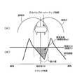
図3は、体積効率向上制御実行中の吸気圧力および排気圧力とクランク角度との関係を示す図である。
図3に示すように、吸気圧力は、脈動が小さく、クランク角度に関わらずにほぼ一定となる。これに対し、排気圧力は、各気筒の排気弁68から排気ガスが間欠的に排出されるのに伴って、大きく脈動(周期的に変動)する。[Volume efficiency improvement control to improve volume efficiency by scavenging effect using exhaust pulsation]
FIG. 3 is a diagram showing the relationship between the intake pressure and exhaust pressure during the execution of the volumetric efficiency improvement control, and the crank angle.
As shown in FIG. 3, the intake pressure has a small pulsation and is substantially constant regardless of the crank angle. In contrast, the exhaust pressure largely pulsates (periodically varies) as the exhaust gas is intermittently discharged from the
図3に示す波形は、排気圧力の脈動(以下、「排気脈動」)の谷となるタイミングと合致するように、正のバルブオーバーラップ期間(O/L期間)が設定されている状態を示している。また、図3に示す波形は、ターボ効率が良い状態で過給がなされることにより、排気圧力に対して吸気圧力(過給圧)が高められた状態を示している。このような状態においては、図3中にハッチングを付して表された領域が、すなわち、バルブオーバーラップ期間において排気圧力よりも吸気圧力の方が高くなる領域が、十分に確保されるようになる。その結果、新気が筒内に流入し易くなるとともに、流入した新気によって筒内の既燃ガスを速やかに排気ポートへ追い出す効果(いわゆる、掃気効果)が十分に得られるようになる。 The waveform shown in FIG. 3 shows a state in which a positive valve overlap period (O / L period) is set so as to coincide with a timing at which a valley of exhaust pressure pulsation (hereinafter referred to as “exhaust pulsation”) occurs. ing. Further, the waveform shown in FIG. 3 shows a state in which the intake pressure (supercharging pressure) is increased with respect to the exhaust pressure by supercharging in a state where the turbo efficiency is good. In such a state, a region shown by hatching in FIG. 3, that is, a region where the intake pressure is higher than the exhaust pressure during the valve overlap period is sufficiently secured. Become. As a result, new air can easily flow into the cylinder, and an effect (so-called scavenging effect) of quickly expelling the burned gas in the cylinder to the exhaust port by the introduced new air can be sufficiently obtained.
上記のような掃気効果は、図3中にハッチングを付して示す領域が大きくなるほど、大きくなる。従って、当該領域が大きく確保されるように、吸気可変動弁機構66を用いた吸気弁の開き時期の調整や排気可変動弁機構70を用いた排気弁の閉じ時期の調整に基づくバルブオーバーラップ期間の調節を行うこととすれば、掃気効果を十分に得ることができるようになる。このようにして、掃気効果を利用する体積効率向上制御を実行することにより、残留ガス量を十分に少なくし、その分、筒内に充填される新気の量を増やすことができる。つまり、吸気の体積効率ηVを増大させることができる。その結果、ディーゼル機関10のトルクを良好に向上させることができる。また、上記のように、上記領域が大きくなるほど、すなわち、排気脈動の谷における圧力の最小値が低くなるほど、掃気効果が大きくなる。従って、掃気効果を高めるうえで、当該最小値を精度良く推定できることは重要である。
The scavenging effect as described above becomes larger as the region indicated by hatching in FIG. 3 becomes larger. Therefore, the valve overlap based on the adjustment of the opening timing of the intake valve using the intake variable
[実施の形態1の特徴部分]
図4は、排気圧力の平均値が高くなる方向に排気脈動が変化する際の2つのパターンA、Bを説明するための図である。尚、図4において、細線で示す波形は、変化前の排気脈動を示し、実線で示す波形は、変化後の排気脈動を示している。
1つ目のパターンAは、図4(A)に示すように、排気圧力が高くなる方向に排気脈動が全体的に変化するオフセット変化である。この場合には、掃気効果を高めるうえで重要な排気脈動の谷における圧力の最小値が上昇することになる。もう1つのパターンBは、図4(B)に示すように、排気脈動の谷における圧力の最小値よりも排気脈動の振幅の方が大きく変化する振幅変化である。この場合には、排気脈動の上記最小値は、あまり変化せずに排気脈動の振幅が大きくなる。図4(B)では、上記最小値が変化していないものを一例として示している。[Characteristics of Embodiment 1]
FIG. 4 is a diagram for explaining two patterns A and B when the exhaust pulsation changes in the direction in which the average value of the exhaust pressure increases. In FIG. 4, the waveform indicated by the thin line indicates the exhaust pulsation before the change, and the waveform indicated by the solid line indicates the exhaust pulsation after the change.
As shown in FIG. 4A, the first pattern A is an offset change in which exhaust pulsation changes as a whole in the direction in which the exhaust pressure increases. In this case, the minimum value of the pressure in the valley of the exhaust pulsation, which is important for enhancing the scavenging effect, is increased. As shown in FIG. 4B, another pattern B is an amplitude change in which the amplitude of the exhaust pulsation changes more greatly than the minimum value of the pressure in the valley of the exhaust pulsation. In this case, the minimum value of the exhaust pulsation does not change so much and the amplitude of the exhaust pulsation increases. FIG. 4B shows an example in which the minimum value does not change.
上記のような2通りのパターンA、Bの何れにおいても、排気圧力の平均値としては上昇するが、オフセット変化の場合には、排気脈動の上記最小値が高くなるのに対し、振幅変化の場合には、排気脈動の上記最小値はあまり変化しない。既述したように、排気脈動の谷における圧力の最小値が低くなるほど、吸気圧力と排気圧力との差圧を大きく確保できるようになり、掃気効果が大きくなる。ところが、従来の内燃機関においては、排気圧力を推定等の手法により平均値として取得したうえで、当該平均値が高くなる場合には掃気効果が小さくなると判断してバルブオーバーラップ期間を短くする制御を行うことが一般的であった。このような従来の制御では、排気脈動の変化が上記オフセット変化であった場合には、排気脈動の上記最小値が上昇するため、バルブオーバーラップ期間を短く制御することは適切であるといえる。しかしながら、排気脈動の変化が上記振幅変化であった場合には、排気脈動の上記最小値はあまり変わらないため、掃気効果が小さくなると判断してバルブオーバーラップ期間を短く制御することは適切な制御とはいえない。 In either of the two patterns A and B as described above, the average value of the exhaust pressure increases, but in the case of offset change, the minimum value of the exhaust pulsation increases, whereas the amplitude change In this case, the minimum value of the exhaust pulsation does not change so much. As described above, the lower the minimum value of the pressure in the valley of the exhaust pulsation, the larger the differential pressure between the intake pressure and the exhaust pressure can be secured, and the scavenging effect increases. However, in the conventional internal combustion engine, after obtaining the exhaust pressure as an average value by a method such as estimation, it is determined that the scavenging effect is reduced when the average value is high, and the valve overlap period is shortened. It was common to do. In such conventional control, when the change in the exhaust pulsation is the offset change, the minimum value of the exhaust pulsation increases, so it can be said that it is appropriate to control the valve overlap period to be short. However, if the change in exhaust pulsation is the change in amplitude described above, the minimum value of the exhaust pulsation does not change so much, so it is appropriate to determine that the scavenging effect is small and control the valve overlap period to be short. That's not true.
以上のように、排気脈動の変化には、上記オフセット変化と上記振幅変化という現象の異なる2つのパターンA、Bが存在する。従って、これら2つのパターンA、Bのそれぞれに対して異なる思想で制御を行わなければ、掃気効果を十分に引き出すことができない。そうであるのに、従来の制御では、両変化の識別がなされておらず、また、物理現象から両変化を識別するパラメータ(因子)が確定されていない。そこで、本実施形態では、上記オフセット変化と上記振幅変化という2つの変化を以下のように規定し、かつ、各変化の要因となる第1パラメータおよび第2パラメータを確定した。 As described above, there are two patterns A and B having different phenomena of the offset change and the amplitude change in the exhaust pulsation change. Accordingly, the scavenging effect cannot be sufficiently obtained unless the two patterns A and B are controlled with different ideas. Nevertheless, in conventional control, both changes are not identified, and a parameter (factor) for identifying both changes is not determined from a physical phenomenon. Therefore, in the present embodiment, the two changes, the offset change and the amplitude change, are defined as follows, and the first parameter and the second parameter that cause each change are determined.
すなわち、本実施形態では、図4(A)に示すオフセット変化は、主に、排気流路面積および排気マニホールド18を流れる排気ガス流量の変化に伴って生ずる変化であるものと規定している。そして、このようなオフセット変化を生じさせる要因となる第1パラメータとしては、過給圧、閉じ側への可変ノズル22cの開度(以下、「VN開度」と略する)の制御量、および吸入空気量(過給圧の検知により代用可)が該当するものとしている。これらの第1パラメータが大きくなると、排気圧力が高くなる。より具体的には、過給圧が高くなると、吸入空気量が増えるので、排気マニホールド18を流れる排気ガス流量が増えて排気圧力が高くなる。閉じ側へのVN開度の制御量が増えると(つまり、可変ノズル22cが絞られると)、排気流路面積が狭くなり、排気圧が高くなる。
That is, in the present embodiment, the offset change shown in FIG. 4A is mainly defined as a change that occurs in accordance with the change in the exhaust passage area and the flow rate of the exhaust gas flowing through the
また、本実施形態では、図4(B)に示す振幅変化は、主に、排気弁68が開く際の排気ガスのエネルギの変化に伴って生ずる変化であるものと規定している。そして、このような振幅変化を生じさせる要因となるパラメータとしては、燃料噴射量、燃料噴射時期の遅角量、排気弁68の開き時期の進角量、および吸気下死点に向けての吸気弁64の閉じ時期の制御量が該当するものとしている。これらの第2パラメータが大きくなると、排気圧力が高くなる。より具体的には、燃料噴射量が増えると、筒内圧が上昇し、排気弁68が開く際の排気ガスの圧力が上昇し、(排気マニホールド18における)排気圧力が高くなる。燃料噴射時期の遅角量が増えると、燃焼が行われる時期が遅くなり、排気弁68が開く際の排気ガスの圧力が上昇し、排気圧力が高くなる。排気弁68の開き時期の進角量が増えると、より筒内圧が高い状態で排気弁68が開くことになるので、排気弁68が開く際の排気ガスの圧力が上昇し、排気圧力が高くなる。また、吸気下死点に向けての吸気弁64の閉じ時期の制御量が大きくなると(つまり、吸気弁64の閉じ時期が吸気下死点に近づけられると)、実圧縮比が高くなり、圧縮端での圧力および温度が上昇する。その結果、排気弁68が開く際の排気ガスの圧力が上昇し、排気圧力が高くなる。
In the present embodiment, the amplitude change shown in FIG. 4B is mainly defined as a change that occurs in accordance with a change in the energy of the exhaust gas when the
そのうえで、本実施形態では、これら第1および第2のパラメータの変化(増大)に基づき、排気圧上昇要因が生じていると判断した場合に、排気脈動の変化が上記オフセット変化であるのか上記振幅変化であるのかに応じて、バルブオーバーラップ期間の制御を異ならせるようにした。 In addition, in the present embodiment, when it is determined that an exhaust pressure increase factor is generated based on the changes (increases) in the first and second parameters, whether the change in the exhaust pulsation is the offset change or the amplitude described above. The valve overlap period is controlled differently depending on whether it is a change.
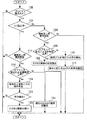
図5は、上記の機能を実現するために、本発明の実施の形態1においてECU50が実行する制御ルーチンを示すフローチャートである。
図5に示すルーチンでは、先ず、アクセルペダルの踏み込みの有無がアクセルポジションセンサ44の出力を利用して判別される(ステップ100)。その結果、アクセルペダルの踏み込みが検知された場合には、掃気効果を利用するためのバルブオーバーラップ期間(O/L)の設定中であるか否かが判別される(ステップ102)。FIG. 5 is a flowchart showing a control routine executed by
In the routine shown in FIG. 5, first, the presence or absence of depression of the accelerator pedal is determined using the output of the accelerator position sensor 44 (step 100). As a result, when depression of the accelerator pedal is detected, it is determined whether or not a valve overlap period (O / L) for using the scavenging effect is being set (step 102).
上記ステップ102において、O/L設定中ではないと判定された場合には、次いで、排気圧の上昇要因が発生したか否かが判別される(ステップ104)。具体的には、上記第1または第2パラメータが大きくなる方向に変化したか否かが各種センサの出力変化や各種アクチュエータの制御値の変化の情報に基づいて判別される。この場合には、例えば、可変ノズル22cの開度が閉じ側に制御されたか否か、若しくは燃料噴射量が増やされたか否か等が判別される。
If it is determined in
上記ステップ104において排気圧力の上昇要因の発生が認められた場合には、排気脈動のオフセット変化による排気圧の上昇であるか否かが判別される(ステップ106)。具体的には、本ステップ106では、第1パラメータ(過給圧、VN開度など)の何れかの増加が検知された場合には、排気脈動のオフセット変化による排気圧力の上昇が生じたと判定され、第2パラメータ(燃料噴射量、燃料噴射時期等)の何れかの増加が検知された場合には、排気脈動の振幅変化による排気圧の上昇が生じたと判定される。
If an increase in the exhaust pressure is found in
上記ステップ106においてオフセット変化による排気圧力の上昇が生じるケースであると判定された場合には、正のO/L期間の設定が禁止される(ステップ108)。これにより、O/L期間が設定されていない状態(O/L期間が微小であるために実質的にO/L期間が設定されていないといえる状態を含む)が維持される。一方、上記ステップ106の判定が不成立である場合、つまり、振幅変化による排気圧力の上昇が生じるケースであると判定された場合には、吸気圧力(過給圧)と排気圧力との差分が算出されたうえで(ステップ110)、当該差分に応じた正のO/L期間が設定される(ステップ112)。具体的には、当該差分が大きいほど、正のO/L期間がより長くなるように制御される。
If it is determined in
一方、上記ステップ102においてO/L設定中であると判定された場合にも、上記ステップ104と同様の処理によって、排気圧力の上昇要因が発生したか否かが判別される(ステップ114)。その結果、排気圧力の上昇要因の発生が認められた場合には、上記ステップ106と同様の処理によって、排気脈動のオフセット変化による排気圧力の上昇であるか否かが判別される(ステップ116)。
On the other hand, if it is determined in
上記ステップ116においてオフセット変化による排気圧の上昇が生じるケースであると判定された場合には、吸気圧力(過給圧)と排気圧力との差分が算出されたうえで(ステップ118)、当該差分が所定の閾値に対して縮小したか否かが判別される(ステップ120)。その結果、上記差分が上記閾値に対して縮小したと判定された場合、つまり、現在のO/L期間では有効な掃気効果を得ることができないと判断できる場合には、正のO/L期間が短くなるように制御される(ステップ122)。尚、本ステップ122では、上記差分の縮小の程度によっては、O/L期間が無くなるように制御してもよい。
If it is determined in
一方、上記ステップ116の判定が不成立である場合、つまり、振幅変化による排気圧の上昇が生じるケースであると判定された場合には、現状のO/L期間が維持される(ステップ124)。尚、本ステップ124では、振幅変化によって排気脈動の圧力の最小値が低くなるケースでは、正のO/L期間を拡大してもよい。
On the other hand, if the determination in
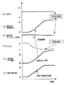
図6は、本発明の実施の形態1におけるバルブオーバーラップ期間の制御によって掃気効果を有効に引き出せる状況を説明するためのタイムチャートである。
図6に示すタイムチャートは、図6(F)に示すように、アクセルペダルの踏み込みに伴う加速時に、上記パラメータの増大の一例として、燃料噴射量が増量された状況を示している。燃料噴射量が増量すると、図6(E)に示すように、排気圧力(の平均値)が上昇する。このような場合に、既述した従来の制御では、図6(D)に示すように、掃気効果を有効に利用できないと判断し、一律に正のO/L期間が縮小されていた。FIG. 6 is a time chart for explaining a situation in which the scavenging effect can be effectively extracted by controlling the valve overlap period in the first embodiment of the present invention.
As shown in FIG. 6F, the time chart shown in FIG. 6 shows a situation where the fuel injection amount is increased as an example of an increase in the parameter during acceleration accompanying depression of the accelerator pedal. When the fuel injection amount increases, as shown in FIG. 6E, the exhaust pressure (average value thereof) increases. In such a case, in the conventional control described above, as shown in FIG. 6D, it is determined that the scavenging effect cannot be effectively used, and the positive O / L period is uniformly reduced.
これに対し、以上説明した図5に示すルーチンの処理によれば、排気圧力の上昇が発生した場合に、排気圧力の上昇要因の識別が行われる。そして、排気脈動の変化がオフセット変化であるのか振幅変化であるのかに応じて、バルブオーバーラップ期間の制御が異なるものとされる。具体的には、図6(B)、(C)に示すように、排気脈動の変化がオフセット変化ではなく振幅変化であると判定された場合には、O/L期間の設定中であれば、図6(A)に示すように、正のO/L期間の設定が維持される。これにより、排気圧力が上昇しても実際には正のO/L期間の設定を抑制する必要のない当該状況下(振幅変化時)において、掃気効果を利用できるようになる。このため、以上のような処理によれば、上記従来の制御と比べ、掃気効果をより有効に引き出すことができるようになる。 On the other hand, according to the routine processing shown in FIG. 5 described above, when the exhaust pressure rises, the cause of the exhaust pressure rise is identified. The control of the valve overlap period differs depending on whether the change in exhaust pulsation is an offset change or an amplitude change. Specifically, as shown in FIGS. 6B and 6C, when it is determined that the change in the exhaust pulsation is not the offset change but the amplitude change, if the O / L period is being set. As shown in FIG. 6A, the setting of the positive O / L period is maintained. As a result, the scavenging effect can be used under the circumstances (when the amplitude changes) where it is not actually necessary to suppress the setting of the positive O / L period even if the exhaust pressure increases. For this reason, according to the above processes, the scavenging effect can be more effectively brought out than the conventional control.
また、上記ルーチンでは、アクセルペダルの踏み込みが検知された場合に、上述したバルブオーバーラップ期間の制御が実行される。アクセルペダルの踏み込みが検知された場合には(より具体的には、アクセルペダルの踏み込みがなされた後の加速初期においては)、要求トルクを発生させるべく燃料噴射量が増やされるが、過給遅れがあるため過給圧は直ちに上昇しない。そのような期間、つまり、第1パラメータである過給圧は増大せずに第2パラメータである燃料噴射量が増大する期間では、排気脈動の変化は上記振幅変化となる。従って、アクセルペダルの踏み込み時(特に加速初期)に、本実施形態のバルブオーバーラップ期間の制御を行うようにすることで、上記従来の制御では生かせなかった期間中において、掃気効果をより有効に引き出すことができるようになる。 Further, in the above routine, when the depression of the accelerator pedal is detected, the above-described control of the valve overlap period is executed. If the accelerator pedal depression is detected (more specifically, at the beginning of acceleration after the accelerator pedal depression), the fuel injection amount is increased to generate the required torque, but the supercharging delay Therefore, the supercharging pressure does not increase immediately. In such a period, that is, a period in which the fuel injection amount, which is the second parameter, increases without increasing the supercharging pressure, which is the first parameter, the change in the exhaust pulsation becomes the above amplitude change. Therefore, when the accelerator pedal is depressed (especially at the initial stage of acceleration), the scavenging effect can be made more effective during the period that cannot be used in the conventional control by controlling the valve overlap period of this embodiment. It can be pulled out.
また、図11を参照して後述するように、ディーゼル機関10における低回転低負荷側の運転領域は、排気エミッション性能の向上のためにEGR制御の実行を伴うモード領域とされている。ディーゼル機関10の運転領域が上記モード領域にある状況からアクセルペダルが踏み込まれることによって、運転領域が当該モード領域の外の領域(高回転高負荷側の領域)に移行する場合がある。このような場合においても、アクセルペダルの踏み込みに伴って燃料噴射量が増やされる。更に、この場合には、モード領域内においてスモーク排出の抑制のために行われていたアフター噴射が実行されなくなるので、タービン22aに供給される排気ガスのエネルギが減少する。その結果、アフター噴射を止めることによりターボ回転数が上がりにくくなり、燃料噴射量が増量されているが、過給圧の立ち上がりが遅れ易い状態となる。従って、このようなアクセルペダルの踏み込み時(モード領域から外れる時)に、本実施形態のバルブオーバーラップ期間の制御を行うようにすることで、上記従来の制御では生かせなかった期間中において、掃気効果をより有効に引き出すことができるようになる。
Further, as will be described later with reference to FIG. 11, the operation region on the low-rotation low-load side in the
尚、上述した実施の形態1においては、ECU50が上記図5に示すルーチンの一連の処理を実行することにより前記第1の発明における「オーバーラップ期間制御手段」が実現されている。
また、ECU50が上記ステップ106または116の処理を実行することにより前記第4の発明における「脈動変化態様判別手段」が実現されている。
また、ECU50が上記ステップ106または116の処理を実行することにより前記第7の発明における「パラメータ変化検知手段」が実現されている。
また、ECU50が上記ステップ100の処理を実行することにより前記第15の発明における「アクセル踏込検知手段」が実現されている。In the first embodiment described above, the “overlap period control means” according to the first aspect of the present invention is realized by the
Further, the “pulsation change mode discriminating means” according to the fourth aspect of the present invention is realized by the
Further, the “parameter change detecting means” according to the seventh aspect of the present invention is realized by the
Further, the “accelerator stepping detection means” according to the fifteenth aspect of the present invention is realized by the
実施の形態2.
次に、図7および図8を参照して、本発明の実施の形態2について説明する。
本実施形態のシステムは、図1、2に示すハードウェア構成を用いて、ECU50に図5に示すルーチンに代えて後述する図8に示すルーチンを実行させることにより実現することができるものである。Embodiment 2. FIG.
Next, a second embodiment of the present invention will be described with reference to FIG. 7 and FIG.
The system of the present embodiment can be realized by causing the
図7は、排気脈動の谷における圧力の最小値の上昇に対する第1および第2パラメータのそれぞれの寄与度を説明するための図である。
図7に示す各パラメータの寄与度は、重回帰解析によって標準回帰係数として得られる値である。上記第1および第2パラメータには、相互に影響し合うパラメータが含まれている。例えば、VN開度を閉じ側に制御すると、排気圧力が上昇する一方でターボ回転数が高くなるので過給圧が高くなることがある。このような寄与度の設定によれば、そのようなパラメータ間の相互作用を含めて、各パラメータが、排気脈動の上記最小値の上昇に対してどれくらいの程度で影響を与えているかを把握することができる。FIG. 7 is a diagram for explaining the respective contributions of the first and second parameters to the increase in the minimum pressure value in the valley of the exhaust pulsation.
The contribution of each parameter shown in FIG. 7 is a value obtained as a standard regression coefficient by multiple regression analysis. The first and second parameters include parameters that affect each other. For example, when the VN opening degree is controlled to the closed side, the exhaust pressure increases, while the turbo rotation speed increases, so the supercharging pressure may increase. According to such setting of the contribution degree, it is understood how much each parameter has an influence on the increase of the minimum value of the exhaust pulsation including the interaction between such parameters. be able to.
図7に示す関係では、上記第1パラメータに該当するパラメータである過給圧(および吸入空気量)および閉じ側へのVN開度の制御量については、寄与度がプラス側の値となるように設定されている。寄与度がプラス側に大きくなることは、第1パラメータの増大によって、排気脈動の上記最小値がより大きく上昇することを意味している。また、過給圧の寄与度は、VN開度の上記制御量の寄与度に対して2倍強となるように設定されている。このことは、過給圧を所定量だけ増大させた場合には、VN開度の上記制御量を所定量だけ増大させた場合と比べ、上記最小値の上昇度合いが2倍強となることを示している。 In the relationship shown in FIG. 7, the contribution degree is a positive value for the boost pressure (and intake air amount) and the control amount of the VN opening degree to the close side, which are parameters corresponding to the first parameter. Is set to Increasing the contribution degree to the plus side means that the minimum value of the exhaust pulsation increases more greatly as the first parameter increases. Further, the contribution of the supercharging pressure is set to be slightly more than twice the contribution of the control amount of the VN opening. This means that when the boost pressure is increased by a predetermined amount, the degree of increase in the minimum value is slightly more than twice that when the control amount of the VN opening is increased by a predetermined amount. Show.
また、図7に示す関係では、上記第2パラメータに該当するパラメータである燃料噴射量、燃料噴射時期の遅角量、排気弁68の開き時期の進角量、および吸気下死点に向けての吸気弁64の閉じ時期の制御量については、寄与度がマイナス側の値となるように設定されている。寄与度がマイナス側に大きくなることは、第2パラメータの増大によって、排気脈動の上記最小値がより大きく下降することを意味している。また、これらの4つのパラメータについてのマイナス側での寄与度の相対的な大小関係の設定は、図7に示す通りである。
Further, in the relationship shown in FIG. 7, the fuel injection amount, the retard amount of the fuel injection timing, the advance amount of the opening timing of the
本実施形態では、上記のように設定された各パラメータの寄与度を、排気圧力の上昇要因が発生した場合のバルブオーバーラップ期間の制御量の調整に反映させるようにしている。以下、図8に示すルーチンを参照して、具体的な処理の一例について説明する。 In the present embodiment, the contribution of each parameter set as described above is reflected in the adjustment of the control amount during the valve overlap period when an increase factor of the exhaust pressure occurs. Hereinafter, an example of specific processing will be described with reference to the routine shown in FIG.
図8は、本発明の実施の形態2におけるバルブオーバーラップ期間の制御を実現するために、ECU50が実行する制御ルーチンを示すフローチャートである。尚、図8において、実施の形態1における図5に示すステップと同一のステップについては、同一の符号を付してその説明を省略または簡略する。
FIG. 8 is a flowchart showing a control routine executed by the
図8に示すルーチンでは、アクセルペダルの踏み込みが検知された場合において(ステップ100)、排気圧の上昇要因が発生したと判定された場合には(ステップ104)、次いで、今回の排気圧力の上昇要因となるパラメータの寄与度が取得される(ステップ200)。ECU50は、第1および第2パラメータのそれぞれに対して上記図7に示すような関係で定められた寄与度を記憶しており、ここでは、該当するパラメータの寄与度の記憶値が取得される。
In the routine shown in FIG. 8, when depression of the accelerator pedal is detected (step 100), if it is determined that an exhaust pressure increase factor has occurred (step 104), then the current increase in exhaust pressure is performed. The contribution degree of the parameter as a factor is acquired (step 200). The
次に、上記ステップ200において取得された寄与度に基づいて、今回の排気圧力の上昇要因となるパラメータの増大に伴って変化した排気脈動の上記最小値が算出(推定)されたうえで、吸気圧力(過給圧)と当該最小値の算出値との差分が算出される(ステップ202)。本実施形態で規定する寄与度は、対応するパラメータが所定量だけ増大した際の排気脈動の最小値の上昇度合いを示す度合いである。従って、今回の排気圧力の上昇要因となるパラメータの増大量と当該パラメータの寄与度が判れば、両者の積から得られる上記最小値の上昇量とECU50に記憶されている排気脈動の所定の基準波形とに基づいて、排気脈動の上記最小値を算出することができる。また、本ステップ202で算出される差分は、次のステップ204において、正のO/L期間を決定する際に使用される。
Next, based on the contribution obtained in
次に、上記ステップ200において取得された寄与度を反映させたO/L期間の制御が実行される(ステップ204)。具体的には、既にO/L期間が設定されている場合であれば、取得された寄与度がプラス側に大きいほど、O/L期間が短くなるように制御され、取得された寄与度がマイナス側に大きいほど、O/L期間が長くなるように制御される。また、現時点でO/L期間が設定されていない場合であれば、取得された寄与度がプラス側の値の場合にはO/L期間の設定が禁止され、取得された寄与度がマイナス側に大きいほど、より長いO/L期間が設定されるように制御される。
Next, control of the O / L period reflecting the contribution obtained in
以上説明した図8に示すルーチンによれば、排気圧力の上昇要因が発生した場合のバルブオーバーラップ期間の調整量が、排気圧力の上昇要因となるパラメータの寄与度の符号の向きおよび大きさに応じて、フィードフォワード的に変更される。図7を参照して既述したように、排気脈動の変化がオフセット変化となるように影響を与える第1パラメータのそれぞれは、寄与度がプラス側の値となるように設定されており、排気脈動の変化が振幅変化となるように影響を与える第2パラメータのそれぞれは、寄与度がマイナス側の値となるように設定されている。つまり、上記図8に示すルーチンの処理において、各パラメータの寄与度を反映させてバルブオーバーラップ期間の制御を行うことによっても、上述した実施の形態1と同様に、排気脈動の変化がオフセット変化である場合と振幅変化である場合とで、バルブオーバーラップ期間の制御を異ならせることが実現されている。そして、上記ルーチンの処理によっても、排気圧力が上昇しても実際には正のO/L期間の設定を抑制する必要のない当該状況下(振幅変化時)において、掃気効果を利用できるようになる。このため、本実施形態の制御によっても、上記従来の制御と比べ、掃気効果をより有効に引き出すことができるようになる。 According to the routine shown in FIG. 8 described above, the adjustment amount of the valve overlap period when the cause of the increase in the exhaust pressure occurs is the direction and magnitude of the sign of the contribution degree of the parameter that causes the increase in the exhaust pressure. Accordingly, it is changed in a feed-forward manner. As described above with reference to FIG. 7, each of the first parameters that influence the change in the exhaust pulsation to be the offset change is set so that the contribution becomes a positive value. Each of the second parameters that affect the pulsation change to change in amplitude is set so that the contribution is a negative value. That is, in the processing of the routine shown in FIG. 8, the exhaust pulsation change is also offset by the control of the valve overlap period by reflecting the contribution of each parameter as in the first embodiment. It is realized that the valve overlap period is controlled differently depending on whether or not the amplitude is changed. Also, the scavenging effect can be used in the above-described routine processing (in the case of an amplitude change) where it is not actually necessary to suppress the setting of the positive O / L period even if the exhaust pressure increases. Become. For this reason, the scavenging effect can be more effectively brought out by the control of the present embodiment as compared with the conventional control.
また、本実施形態では、上記図7に示すように、第1パラメータに関してはプラス側においてパラメータ毎に寄与度の大きさが設定されており、第2パラメータに関してはマイナス側においてパラメータ毎に寄与度の大きさが設定されている。これにより、排気圧力の上昇要因の発生が認められた場合に、排気脈動の変化がオフセット変化であるのか振幅変化であるのかに応じてバルブオーバーラップ期間の制御を切り替えるだけでなく、今回の排気圧力の上昇要因となるパラメータの寄与度のプラス側或いはマイナス側の大きさ(つまり、排気脈動の最小値の変化への影響の大きさ)に応じて、バルブオーバーラップ期間の制御量が調整されるようになる。より具体的には、当該寄与度が大きいほど、O/L期間の制御量が大きく調整される。このため、排気圧力の上昇が認められた場合に、上述した実施の形態1の制御と比べ、掃気効果をより引き出せるようにバルブオーバーラップ期間をより正確に制御できるようになる。 Further, in the present embodiment, as shown in FIG. 7, the magnitude of contribution is set for each parameter on the plus side with respect to the first parameter, and the contribution degree is set for each parameter on the minus side with respect to the second parameter. The size of is set. As a result, when an increase in the exhaust pressure is observed, not only the control of the valve overlap period is switched depending on whether the change in the exhaust pulsation is an offset change or an amplitude change, The control amount of the valve overlap period is adjusted according to the positive or negative magnitude of the contribution of the parameter that causes the pressure increase (that is, the magnitude of the influence on the change in the minimum value of the exhaust pulsation). Become so. More specifically, the control amount in the O / L period is adjusted to be larger as the contribution is larger. For this reason, when an increase in the exhaust pressure is recognized, the valve overlap period can be controlled more accurately so that the scavenging effect can be extracted more than the control of the first embodiment described above.
ところで、上述した実施の形態2においては、各パラメータの寄与度を反映させてバルブオーバーラップ期間の制御を行うことによって、排気脈動の変化がオフセット変化である場合と振幅変化である場合とで、バルブオーバーラップ期間の制御が異なるものとされている。しかしながら、本発明におけるバルブオーバーラップ期間の制御は、このような手法に限定されるものではなく、例えば、排気脈動の詳細な波形を検知可能な排気圧力センサを備えている場合には、次のような制御を行うようにしてもよい。すなわち、先ず、当該排気圧力センサにより検知される排気脈動の最小値を利用して、吸気圧力との差分を取得する。そして、その後に第1または第2のパラメータがある量だけ大きくなった場合に、変化が生じたパラメータの変化量と当該パラメータの上記寄与度とを利用して、排気脈動の最小値の変化を推定することで、当該パラメータの変化後の上記差分を推定する。そして、推定された差分に応じた期間となるようにバルブオーバーラップ期間をフィードフォワード的に制御する。このような制御によれば、上記排気圧力センサにより現状の上記差分を把握することができるので、第1または第2パラメータの変化に応じてバルブオーバーラップ期間をフィードフォワード的に制御する際の制御基準値を正確に得られるようになる。そして、排気圧力の上昇要因(第1または第2パラメータ)に応じたバルブオーバーラップ期間の制御量を当該上昇要因毎(パラメータ毎)に正確に区別することが可能となる。 By the way, in Embodiment 2 mentioned above, by controlling the valve overlap period by reflecting the contribution degree of each parameter, when the change of exhaust pulsation is an offset change and when it is an amplitude change, The control of the valve overlap period is different. However, the control of the valve overlap period in the present invention is not limited to such a method. For example, when an exhaust pressure sensor capable of detecting a detailed waveform of exhaust pulsation is provided, the following is performed. Such control may be performed. That is, first, a difference from the intake pressure is acquired using the minimum value of the exhaust pulsation detected by the exhaust pressure sensor. When the first or second parameter subsequently increases by a certain amount, the change in the minimum value of the exhaust pulsation is changed using the change amount of the parameter in which the change has occurred and the above-described contribution of the parameter. By estimating, the difference after the change of the parameter is estimated. Then, the valve overlap period is controlled in a feed-forward manner so that a period corresponding to the estimated difference is reached. According to such control, since the present difference can be grasped by the exhaust pressure sensor, control when the valve overlap period is controlled in a feed-forward manner according to the change of the first or second parameter. The reference value can be obtained accurately. Then, it becomes possible to accurately distinguish the control amount of the valve overlap period according to the exhaust pressure increase factor (first or second parameter) for each increase factor (for each parameter).
また、排気脈動の詳細な波形を検知可能な排気圧力センサを備えている場合には、例えば、当該排気圧力センサによって得られる排気脈動の波形を参照して、排気脈動の変化が上記オフセット変化であるのか上記振幅変化であるのかを判断し、その判断結果に応じて、バルブオーバーラップ期間の制御を異ならせてもよい。 Further, when an exhaust pressure sensor capable of detecting a detailed waveform of exhaust pulsation is provided, for example, referring to the exhaust pulsation waveform obtained by the exhaust pressure sensor, the change in exhaust pulsation is the offset change described above. It may be determined whether there is an amplitude change or the amplitude change, and the control of the valve overlap period may be varied depending on the determination result.
尚、上述した実施の形態2においては、ECU50が上記図8に示すルーチンの一連の処理を実行することにより前記第1の発明における「オーバーラップ期間制御手段」が実現されている。
In the second embodiment described above, the “overlap period control means” according to the first aspect of the present invention is realized by the
実施の形態3.
次に、図9および図10を参照して、本発明の実施の形態3について説明する。
本実施形態のシステムは、図1、2に示すハードウェア構成を用いて、ECU50に図5に示すルーチンに代えて後述する図10に示すルーチンを実行させることにより実現することができるものである。Embodiment 3 FIG.
Next, Embodiment 3 of the present invention will be described with reference to FIG. 9 and FIG.
The system of the present embodiment can be realized by causing the
図9は、本発明の実施の形態3において、第1および第2パラメータのそれぞれの変化に伴う排気脈動の変化を算出するために使用される実験式(関係式)の傾向を表した図である。より具体的には、図9(A)は、上記オフセット変化を生じさせる要因となる第1パラメータに対する排気脈動の変化を規定した実験式Aの傾向を示しており、図9(B)は、上記振幅変化を生じさせる要因となる第2パラメータの変化に対する排気脈動の変化を規定した実験式Bの傾向を示している。 FIG. 9 is a diagram showing a tendency of an empirical formula (relational formula) used for calculating a change in exhaust pulsation accompanying a change in each of the first and second parameters in the third embodiment of the present invention. is there. More specifically, FIG. 9 (A) shows a tendency of the empirical formula A that defines the change in exhaust pulsation with respect to the first parameter that causes the offset change, and FIG. The tendency of the empirical formula B that defines the change in exhaust pulsation with respect to the change in the second parameter that causes the amplitude change is shown.
図9(A)に示すように、実験式Aでは、第1パラメータが大きくなるほど(つまり、排気圧力が上昇する側への第1パラメータの変化量が大きくなるほど)、排気脈動の変化量におけるオフセット変化分が大きくなるように規定されている。また、実験式Aでは、第1パラメータの値の増減に応じて、排気脈動の変化量における振幅変化分があまり変化しないように規定されている。このような実験式Aの傾向は、上記図4(A)に示すオフセット変化の傾向を捉えたものとなっている。また、実施の形態2において既述したように、第1パラメータの中のパラメータ間(例えば、過給圧とVN開度)で、排気脈動の変化に対する寄与度が異なるものとなる。従って、第1パラメータに関する実験式Aは、厳密には、パラメータが過給圧であるかVN開度であるかに応じて、パラメータの値の増減に応じた排気脈動の変化の度合いが異なるように規定されるものである。 As shown in FIG. 9A, in the empirical formula A, as the first parameter increases (that is, as the amount of change in the first parameter toward the side where the exhaust pressure increases), the offset in the amount of change in exhaust pulsation increases. It is stipulated that the amount of change is large. Further, in the empirical formula A, it is defined that the amplitude change amount in the exhaust pulsation change amount does not change so much according to the increase or decrease of the value of the first parameter. Such a tendency of the empirical formula A captures the tendency of the offset change shown in FIG. Further, as already described in the second embodiment, the degree of contribution to the change in exhaust pulsation differs between the parameters in the first parameter (for example, the supercharging pressure and the VN opening degree). Therefore, strictly speaking, the empirical formula A relating to the first parameter is such that the degree of change in the exhaust pulsation according to the increase / decrease in the value of the parameter varies depending on whether the parameter is the supercharging pressure or the VN opening. It is stipulated in.
一方、図9(B)に示すように、実験式Bでは、第2パラメータが大きくなるほど(つまり、排気圧力が上昇する側への第2パラメータの変化量が大きくなるほど)、排気脈動の変化量における振幅変化分が大きくなるように規定されている。また、実験式Bでは、第2パラメータが大きくなることに対して、排気脈動の変化量におけるオフセット変化分が同じままであるかマイナス側に大きくなるように規定されている。このような実験式Bの傾向は、上記図4(B)に示す振幅変化の傾向を捉えたものとなっている。また、第2パラメータに関する実験式Bも、厳密には、第1パラメータと同様に、第2パラメータの中のパラメータ間(例えば、燃料噴射量と燃料噴射時期)で、パラメータの値の増減に応じた排気脈動の変化の度合いが異なるように規定されるものである。 On the other hand, as shown in FIG. 9B, in the empirical formula B, the amount of change in exhaust pulsation increases as the second parameter increases (that is, the amount of change in the second parameter toward the side where the exhaust pressure increases). It is specified that the amount of amplitude change at is large. Further, in the experimental formula B, it is defined that the offset change amount in the change amount of the exhaust pulsation remains the same or increases toward the minus side as the second parameter increases. Such a tendency of the empirical formula B captures the tendency of the amplitude change shown in FIG. Strictly speaking, the empirical formula B relating to the second parameter also corresponds to the increase or decrease of the parameter value between the parameters in the second parameter (for example, the fuel injection amount and the fuel injection timing), similarly to the first parameter. Further, the degree of change in exhaust pulsation is defined to be different.
本実施形態では、第1および第2パラメータのそれぞれの変化に対する排気脈動の変化の傾向(関係)を、上記実験式AおよびBのような実験式を用いて規定したうえで、ディーゼル機関10の運転中における各パラメータの変化に伴う排気脈動の変化をパラメータ毎に算出するようにした。そして、そのようにして算出(推定)されるパラメータ毎の排気脈動の変化分を足し合わせて得た排気脈動の波形(特に谷における圧力の最小値)に基づいて、バルブオーバーラップ期間を制御するようにした。
In the present embodiment, the tendency (relation) of the exhaust pulsation change with respect to each change of the first and second parameters is defined using empirical formulas such as the above empirical formulas A and B, and then the
図10は、上記の機能を実現するために、本実施の形態3においてECU50が実行する制御ルーチンを示すフローチャートである。尚、図10において、実施の形態1における図5に示すステップと同一のステップについては、同一の符号を付してその説明を省略または簡略する。
FIG. 10 is a flowchart showing a control routine executed by the
図10に示すルーチンでは、アクセルペダルの踏み込みが検知された場合において(ステップ100)、排気圧の上昇要因が発生したと判定された場合には(ステップ104)、次いで、ステップ300〜ステップ310の判別処理がそれぞれ実行される。これらのステップの処理は、何れも、第1パラメータまたは第2パラメータが大きくなったか否かを判別する処理である。 In the routine shown in FIG. 10, when depression of the accelerator pedal is detected (step 100), if it is determined that an exhaust pressure increase factor has occurred (step 104), then steps 300 to 310 are performed. Each determination process is executed. The processes in these steps are processes for determining whether or not the first parameter or the second parameter has increased.
具体的には、ステップ300では、VN開度が閉じ側に制御されたか(閉じ側へのVN開度の制御量が増えたか)否かが判別される。ステップ302では、過給圧(吸入空気量)が増えたか否かが判別される。ステップ304では、燃料噴射量が増えたか否かが判別される。ステップ306では、燃料噴射時期の遅角量が増えたか(例えば、メイン噴射後にアフター噴射が行われたか)否かが判別される。ステップ308では、排気弁68の開き時期の進角量が増えたか否かが判別される。ステップ310では、吸気下死点に向けての吸気弁64の閉じ時期の制御量が増えたか否かが判別される。
Specifically, in
上記ステップ300において、閉じ側へのVN開度の制御量が増えたと判定された場合には、VN開度の上記制御量の変化に対する排気脈動の変化を規定した実験式A1(上記図9に示す実験式Aのような傾向を有する実験式)を用いて、VN開度の上記制御量の変化に対する排気脈動のオフセット変化分および振幅変化分が算出される(ステップ312)。
If it is determined in
上記ステップ302において、過給圧が増えたと判定された場合には、過給圧の変化に対する排気脈動の変化を規定した実験式A2(≒実験式A)を用いて、過給圧の変化に対する排気脈動のオフセット変化分および振幅変化分が算出される(ステップ314)。
If it is determined in
上記ステップ304において、燃料噴射量が増えたと判定された場合には、燃料噴射量の変化に対する排気脈動の変化を規定した実験式B1(≒実験式B)を用いて、燃料噴射量の変化に対する排気脈動のオフセット変化分および振幅変化分が算出される(ステップ316)。
If it is determined in
上記ステップ306において、燃料噴射時期の遅角量が増えたと判定された場合には、燃料噴射時期の遅角量の変化に対する排気脈動の変化を規定した実験式B2(≒実験式B)を用いて、燃料噴射時期の遅角量の変化に対する排気脈動のオフセット変化分および振幅変化分が算出される(ステップ318)。
If it is determined in
上記ステップ308において、排気弁68の開き時期の進角量が増えたと判定された場合には、排気弁68の開き時期の進角量の変化に対する排気脈動の変化を規定した実験式B3(≒実験式B)を用いて、排気弁68の開き時期の進角量の変化に対する排気脈動のオフセット変化分および振幅変化分が算出される(ステップ320)。
If it is determined in
上記ステップ310において、吸気下死点に向けての吸気弁64の閉じ時期の制御量が増えたと判定された場合には、吸気弁64の閉じ時期の上記制御量の変化に対する排気脈動の変化を規定した実験式B4(≒実験式B)を用いて、吸気弁64の閉じ時期の上記制御量の変化に対する排気脈動のオフセット変化分および振幅変化分が算出される(ステップ322)。
If it is determined in
次に、上記ステップ312〜322の処理により各パラメータとの関係で算出が行われた排気脈動のオフセット変化分および振幅変化分の積算がそれぞれ実行される(ステップ324、326)。次いで、排気脈動の所定の基準波形に対して、上記ステップ324および326で算出されたオフセット変化分および振幅変化分のそれぞれの積算値を反映させることにより、今回の排気圧力の上昇要因の発生に伴う変化後の排気脈動の波形が算出(推定)される(ステップ328)。
Next, integration of an offset change and an amplitude change of the exhaust pulsation calculated in relation to each parameter by the processing in
次に、吸気圧力(過給圧)と上記ステップ328において算出された排気脈動の最小値との差分が算出される(ステップ330)。次いで、算出された差分に応じて、正のバルブオーバーラップ期間の補正量が算出される(ステップ332)。より具体的には、上記ステップ324〜328の処理によれば、上記オフセット変化を生じさせる要因である第1パラメータが大きくなった場合であれば、排気脈動の最小値が大きくなるように排気脈動の波形が算出される。このため、この場合には、上記差分が小さくなる。一方、上記振幅変化を生じさせる要因であると第2パラメータが大きくなった場合であれば、排気脈動の最小値は同じ値のままで若しくは当該最小値が小さくなるように排気脈動の波形が算出される。このため、この場合には、上記差分は変わらないか若しくは大きくなる。本ステップ332では、上記差分が小さくなる場合には、O/L期間の設定中であればO/L期間が短くなるように制御され、O/L期間が未設定であった場合であればO/L期間の設定が禁止される。上記差分が変わらない場合には、O/L期間の設定が維持される。また、上記差分が大きくなる場合には、O/L期間の設定中であればO/L期間が長くなるように制御され、O/L期間が未設定であった場合であればO/L期間の設定が実行される。 Next, the difference between the intake pressure (supercharging pressure) and the minimum value of the exhaust pulsation calculated in step 328 is calculated (step 330). Next, a correction amount for the positive valve overlap period is calculated according to the calculated difference (step 332). More specifically, according to the processing of steps 324 to 328, if the first parameter that causes the offset change is increased, the exhaust pulsation is set so that the minimum value of the exhaust pulsation increases. Is calculated. For this reason, in this case, the difference becomes small. On the other hand, if the second parameter increases as a factor causing the amplitude change, the exhaust pulsation waveform is calculated so that the minimum value of the exhaust pulsation remains the same or becomes smaller. Is done. Therefore, in this case, the difference does not change or increases. In this step 332, when the difference is small, the O / L period is controlled to be shortened if the O / L period is being set, and if the O / L period is not set. Setting of the O / L period is prohibited. When the difference does not change, the setting of the O / L period is maintained. Further, when the difference is large, the O / L period is controlled to be long if the O / L period is being set, and if the O / L period is not set, the O / L period is controlled. Period setting is performed.
以上説明した図10に示すルーチンによれば、排気圧力の上昇要因が発生した場合に、排気圧力の上昇要因となる第1または第2パラメータのそれぞれの排気脈動の変化分を足し合わせて得た排気脈動の波形に基づいて、バルブオーバーラップ期間が制御される。図9(A)および(B)に示す実験式AおよびBによれば、排気脈動の変化がオフセット変化となるように影響を与える第1パラメータについては、第1パラメータが大きくなるほど、オフセット変化分が大きくなるように規定されており、排気脈動の変化が振幅変化となるように影響を与える第2パラメータについては、第2パラメータが大きくなるほど、振幅変化分が大きくなるように規定されている。つまり、上記図10に示すルーチンの処理において、上記実験式A、Bのような傾向を有する各自の実験式A1、B1等に従ってパラメータ毎に算出した排気脈動の変化分を足し合わせて得た排気脈動の波形に基づいてバルブオーバーラップ期間の制御を行うことによっても、上述した実施の形態1と同様に、排気脈動の変化がオフセット変化である場合と振幅変化である場合とで、バルブオーバーラップ期間の制御を異ならせることが実現されている。そして、上記ルーチンの処理によっても、排気圧力が上昇しても実際には正のO/L期間の設定を抑制する必要のない当該状況下(振幅変化時)において、掃気効果を利用できるようになる。このため、本実施形態の制御によっても、上記従来の制御と比べ、掃気効果をより有効に引き出すことができるようになる。 According to the routine shown in FIG. 10 described above, when an increase factor of the exhaust pressure occurs, the change in the exhaust pulsation of each of the first or second parameter that becomes the increase factor of the exhaust pressure is added. The valve overlap period is controlled based on the exhaust pulsation waveform. According to the empirical formulas A and B shown in FIGS. 9A and 9B, the first parameter that affects the exhaust pulsation change to be the offset change, the larger the first parameter, the more the offset change. The second parameter that affects the change in the exhaust pulsation to become the amplitude change is specified so that the larger the second parameter is, the larger the amplitude change is. That is, in the routine processing shown in FIG. 10, the exhaust gas obtained by adding the exhaust pulsation changes calculated for each parameter in accordance with the respective experimental equations A1, B1, etc. having the tendency as the above experimental equations A, B. Also by controlling the valve overlap period based on the pulsation waveform, the valve overlap between the case where the change in the exhaust pulsation is an offset change and the case where the change is an amplitude change, as in the first embodiment described above. Different control of the period is realized. Also, the scavenging effect can be used in the above-described routine processing (in the case of an amplitude change) where it is not actually necessary to suppress the setting of the positive O / L period even if the exhaust pressure increases. Become. For this reason, the scavenging effect can be more effectively brought out by the control of the present embodiment as compared with the conventional control.
尚、上述した実施の形態3においては、ECU50が上記図10に示すルーチンの一連の処理を実行することにより前記第1の発明における「オーバーラップ期間制御手段」が実現されている。
また、ECU50が上記ステップ300〜328の処理を実行することにより前記第12の発明における「脈動波形推定手段」が実現されている。In the third embodiment described above, the “overlap period control means” according to the first aspect of the present invention is implemented when the
Further, the “pulsation waveform estimating means” in the twelfth aspect of the present invention is realized by the
実施の形態4.
次に、図11乃至図16を参照して、本発明の実施の形態4について説明する。
本実施形態のシステムは、図1、2に示すハードウェア構成を用いて、ECU50に図2に示すルーチンに代えて後述する図14に示すルーチンを実行させることにより実現することができるものである。Embodiment 4 FIG.
Next, a fourth embodiment of the present invention will be described with reference to FIGS.
The system of the present embodiment can be realized by causing the
図11は、排気系容積を調整するための遮断弁42の開閉領域を説明するための図である。図12は、遮断弁42の開閉に伴う排気脈動の波形の変化を表した図である。
図11に示すように、ディーゼル機関10の運転領域における低回転低負荷側の領域は、EGR制御の実行を伴うモード領域となっている。図12に示すように、遮断弁42を閉じると、排気系容積が縮小するので排気脈動が強くなる。そこで、当該モード領域よりも高負荷側の領域では、掃気効果を利用してトルク向上を図るため、遮断弁42が閉じられるようになっている。ただし、遮断弁42を閉じた場合には、図12に示すように、排気圧力のピーク値が上昇する。このため、ターボ過給機22(タービン22a)の保護などの観点により、図11に示すように、高回転高負荷側の運転領域では、遮断弁42を開くようにする必要がある。FIG. 11 is a view for explaining an open / close region of the shut-off
As shown in FIG. 11, the region on the low rotation and low load side in the operation region of the
図13は、本発明の実施の形態4の制御の概要を説明するためのタイムチャートである。
図13中において「掃気効果大ライン」と指示されたトルク曲線は、遮断弁42が閉じていることで排気脈動が大きく生成されている状態で排気脈動が谷となるタイミングにO/L期間を合致させることにより、掃気効果を有効に利用している場合の曲線を示している。このような掃気効果の利用中において、上述したターボ過給機22の保護などの理由により遮断弁42が何らの配慮なしに開かれると、排気脈動が弱くなるので、掃気効果の減少、或いは、吸気圧力が排気圧力よりも低くなることによる吸気側への排気ガスの逆流が生ずることとなる。その結果、図13中に「掃気効果判断ミスライン」と指示されたトルク曲線が示すように、一時的にトルクが大きく低下するという次なる課題が発生する。FIG. 13 is a time chart for explaining the outline of the control according to the fourth embodiment of the present invention.
The torque curve instructed as “large scavenging effect line” in FIG. 13 shows the O / L period at the timing when the exhaust pulsation becomes a valley when the
そこで、本実施形態では、遮断弁42が開いている時と閉じている時の双方での排気脈動の状態をディーゼル機関10の運転中に常時推定(予測)するようにした。そして、ディーゼル機関10の運転中に遮断弁42を開く要求が出された際に、遮断弁42が開かれると有効な掃気効果が得られなくなると判断した場合には、図13中に「掃気効果あきらめライン」と指示されたトルク曲線が示すように、遮断弁42の開放に先立って、バルブオーバーラップ期間が無くなるように制御するようにした。この場合には、更に、遮断弁42の開放に先立って、バルブオーバーラップ期間が無くなるようにする上記制御と同時若しくは当該制御の実行後に、VN開度を閉じ側の開度に制御するようにした。言い換えれば、先ず、バルブオーバーラップ期間が無くなるように制御され、当該制御と同時若しくは当該制御の実行後に、VN開度が閉じ側の開度に制御される。そして、その後に、遮断弁42が開放される。遮断弁42の開放に先立って、このようなVN開度の制御をも実行することにより、遮断弁42の開放後にVN開度を閉じ側の開度に制御する場合と比べ、VN開度の調整により速やかに過給圧を高めることができるので、図13に示すように、過給遅れを最小限に抑えることができる。
Therefore, in this embodiment, the state of exhaust pulsation both when the shut-off
一方、本実施形態では、遮断弁42を開く要求が出された際に、遮断弁42を開いても掃気効果を確保できると判断した場合には、図13中に「掃気効果継続ライン」と指示された一点鎖線のトルク曲線が示すように、低くなる掃気効果に合わせるようにバルブオーバーラップ期間を適切に縮小したうえで、掃気効果を継続的に利用するようにした。
On the other hand, in the present embodiment, when it is determined that the scavenging effect can be secured even when the shut-off
図14は、上記の機能を実現するために、本実施の形態4においてECU50が実行する制御ルーチンを示すフローチャートである。
図14に示すルーチンでは、掃気効果の利用中に遮断弁42を開く要求があるか否かが判別される(ステップ400)。その結果、遮断弁42を開く要求があると判定された場合には、現在のO/L期間の制御量が取得される(ステップ402)。FIG. 14 is a flowchart showing a control routine executed by the
In the routine shown in FIG. 14, it is determined whether or not there is a request to open the shut-off
次に、遮断弁42が開いている時と閉じている時の双方での排気脈動の状態(排気脈動の谷における圧力の最小値)が取得される(ステップ404)。本ステップ404では、上記図8に示すルーチンのステップ202の処理と同様の処理によって排気脈動の状態(上記最小値)が算出されるものとする。図15は、遮断弁42を開いた状態での、排気脈動の谷における圧力の最小値の上昇に対する第1および第2パラメータのそれぞれの寄与度を説明するための図である。尚、上記図7に示す寄与度は、遮断弁42が閉じた状態での寄与度を示している。既述したように、遮断弁42が開いている状態では、遮断弁42が閉じている状態と比べ、排気脈動が弱くなる。従って、図15を図7と比較して判るように、遮断弁42が開いている状態での寄与度は、遮断弁42が閉じている状態での寄与度に対して、各パラメータ間の相対的な大小の比率は同じままで全体的に小さくなるように設定されている。
Next, the exhaust pulsation state (the minimum value of the pressure in the valley of the exhaust pulsation) both when the shut-off
上記ステップ404では、上記図7に示す寄与度と上記図15に示す寄与度とを参照して、遮断弁42が開いている時と閉じている時の双方での排気脈動の状態(排気脈動の上記最小値)が取得される。尚、このような寄与度を用いた排気脈動の状態の取得に代え、上述した実施の形態3の手法のように、パラメータ毎に排気脈動の変化を規定した実験式を用いて、遮断弁42が開いている時と閉じている時の双方での排気脈動の状態を算出して取得するものであってもよい。この場合には、遮断弁42が開いている時と閉じている時のそれぞれに対応する実験式を予め規定して備えておくようにする。
In
次に、遮断弁42が開いている時の排気脈動の状態の取得(予測)結果に基づき、遮断弁42が開かれると有効な掃気効果が得られなくなる状況であるか否かが判別される(ステップ406)。より具体的には、本ステップ406では、遮断弁42が開いている時の排気脈動の上記最小値の取得(予測)結果と吸気圧力の検出値とに基づいて、吸気圧力が排気圧力よりも高くなる領域が所定の閾値以下に減少したか、或いは吸気圧力が排気圧力よりも高くなる領域が逆転したか否かが判別される。その結果、本ステップ406の判定が不成立である場合、すなわち、遮断弁42が開かれても掃気効果を維持できる状況であると判定(予測)された場合には、低くなる掃気効果に合わせるようにO/L期間が適切に縮小されることで正のO/L期間の設定が維持され(ステップ408)、掃気効果が継続的に利用される。
Next, based on the acquisition (prediction) result of the state of exhaust pulsation when the shut-off
一方、上記ステップ406において、遮断弁42が開かれると有効な掃気効果が得られなくなる状況であると判定(予測)された場合には、次いで、遮断弁42が開いている時と閉じている時の双方に対して、掃気効果の程度を示す指標値が算出される(ステップ410)。具体的には、本ステップ410では、吸気圧力が排気圧力よりも高くなる領域の大きさに基づいて、当該領域が大きいほど、上記指標値が大きくなるように算出される。尚、吸気圧力が排気圧力よりも高くなる領域の大きさは、吸気圧力と排気圧力との差分に基づき取得することができる。
On the other hand, if it is determined (predicted) in
次に、上記ステップ410において算出された、遮断弁42が開いている時と閉じている時の掃気効果の上記指標値の差に基づいて、遮断弁42が開かれるとトルク段差が発生するか否かが判別される(ステップ412)。具体的には、本ステップ412では、上記指標値の上記差が所定の閾値よりも大きい場合には、トルク段差が発生すると判断される。
Next, based on the difference between the index values of the scavenging effect when the shut-off
上記ステップ412において、遮断弁42が開かれるとトルク段差が発生すると判定された場合には、正のO/L期間が縮小若しくは当該O/L期間の設定が禁止される(ステップ414)。次いで、VN開度が閉じ側の開度に制御され、(ステップ416)、その後、遮断弁42が開放される(ステップ418)。
If it is determined in
以上説明した図14に示すルーチンによれば、掃気効果の利用中において遮断弁42を開く要求が出された際に、遮断弁42が開かれると有効な掃気効果が得られなくなると判断した場合には、遮断弁42の開放に先立って、バルブオーバーラップ期間が無くなるように制御される。掃気効果の利用中において遮断弁42が開かれると有効な掃気効果が得られなくなる条件を予測できずに遮断弁42が開かれると、既述したようにトルクの低下が生ずる。そして、このようなトルク低下が発生したことを吸入空気量の変化によって事後的に検知してO/L期間の設定を禁止するようにする手法(図13中の「掃気効果判断ミスライン」参照)では、ディーゼル機関10の加速不良やドライバビリティの悪化が生じてしまう。その一方で、このような問題を回避するために遮断弁42が開かれる前に一律にO/L期間の設定を禁止するようにすると、遮断弁42が開かれても掃気効果が確保できる状況であった場合には、得られるはずの掃気効果が得られなくなる。これにより、ディーゼル機関10の加速不良やドライバビリティの悪化が生じてしまう。これに対し、上記ルーチンの処理によれば、掃気効果の利用中において遮断弁42を開く要求が出された際に、遮断弁42が開かれると有効な掃気効果が得られなくなる状況であるか否かの予測が行われたうえで、予測結果に応じて、バルブオーバーラップ期間を遮断弁42の開放に先立って縮小若しくは禁止するかどうかが判断される。これにより、掃気効果の利用中において遮断弁42を開く要求が出された際に、ディーゼル機関10の加速不良やドライバビリティの悪化を良好に抑制することが可能となる。
According to the routine shown in FIG. 14 described above, when a request to open the shut-off
また、上記ルーチンによれば、掃気効果の利用中において遮断弁42を開く要求が出された際に、遮断弁42が開かれると有効な掃気効果が得られなくなると判断した場合には、バルブオーバーラップ期間が無くなるようにする上記制御だけでなくVN開度を閉じる制御が、遮断弁42の開放に先立って実行される。掃気効果を有効に得るためには、排気圧力が低い状態が必要であるため、開き側のVN開度が使用される。このため、掃気効果の利用中は、絶対値としては過給圧が低くなっている。その結果、そのような掃気効果の利用中に遮断弁42を開く際にO/L期間を狭めて掃気効果の利用を諦めるようにすると、過給圧が低い状態となる。このため、遮断弁42が開いた後にVN開度を閉じ側の開度に制御することによって過給圧を確保しようとすると、図13中に示すようにトルク段差(トルクの上昇が停滞している状態)が発生してしまう。このようなトルク段差は、加速停止感を生じさせてしまう。これに対し、上記ルーチンの処理によれば、VN開度を閉じる制御が、遮断弁42の開放に先立って実行される。これにより、O/L期間を狭めて遮断弁42を開いた際に生ずる過給遅れを最小限に抑制することができる。
Further, according to the above routine, when a request to open the shut-off
図16は、遮断弁42を開いた際に掃気効果を諦めてVN開度を閉じ側の開度にする制御Aに対する、遮断弁42を開いた際に掃気効果を継続する制御Bのメリットを説明するための図である。
図16は、吸気圧力(過給圧)と排気圧力との関係でターボ過給機22の特性を表した図である。図16に示すように、吸気圧力が比較的低い領域では、ターボ効率が良く、排気圧力の上昇に対して吸気圧力が良好に上昇するが、吸気圧力が比較的高い領域では、ターボ効率が悪く、排気圧力の上昇に対する吸気圧力の上昇が鈍くなる。従って、ターボ効率の良い低吸気圧力領域では、吸気圧力が排気圧力(排気脈動の最小値)よりも高い状況を作り易く、掃気効果を利用し易くなる。逆に、ターボ効率の悪い高吸気圧力領域では、吸気圧力が排気圧力(排気脈動の最小値)よりも高い状況を作りにくく、掃気効果を利用しにくくなる。FIG. 16 shows the merit of the control B in which the scavenging effect is continued when the shut-off
FIG. 16 is a diagram showing the characteristics of the
ターボ効率の良い上記領域は、ターボ効率の優れた開き側の所定開度にVN開度を制御することで実現することができる。また、図16に示すように、このようなターボ効率の良い開度にVN開度が制御された状態からVN開度が閉じ側の開度に制御された場合、或いは当該状態からディーゼル機関10の運転領域が高回転高負荷領域に移行した場合には、ターボ効率の良い領域からターボ効率の悪い領域に移行することになる。
The above-described region with good turbo efficiency can be realized by controlling the VN opening to a predetermined opening on the opening side with excellent turbo efficiency. In addition, as shown in FIG. 16, when the VN opening is controlled to the closing side from the state where the VN opening is controlled to such an opening with good turbo efficiency, or from this state, the
掃気効果の利用中において遮断弁42を開く要求が出された際には、状況によっては、VN開度をターボ効率の良い開度に維持したまま低過給圧下で掃気効果を利用する制御Aと、O/L期間を狭めて掃気効果を諦めつつVN開度を閉じ側の開度に制御することで高過給圧を得るようにする制御Bのどちらを実行した場合であっても、要求トルク(吸入空気量)を得ることができる場合がある。そのような状況下では、ターボ効率の良い状態を使用することで燃費上有利となる上記制御A(掃気効果利用継続)を選択することが好ましい。
When a request to open the shut-off
尚、上述した実施の形態4においては、ECU50が、上記ステップ418の処理を実行することにより前記第13の発明における「排気容積調整手段」が、上記ステップ404の処理を実行することにより前記第13の発明における「排気脈動取得手段」が、上記ステップ406、410、および412の処理を実行することにより前記第13の発明における「掃気効果予測手段」が、上記ステップ418の処理に先立って上記ステップ414の処理を実行することにより前記第13の発明における「オーバーラップ制御先出し実行手段」が、それぞれ実現されている。
また、ECU50が、上記ステップ416の処理を実行することにより前記第14の発明における「ノズル開度制御手段」が、上記ステップ418の処理に先立って上記ステップ416の処理を実行することにより前記第14の発明における「ノズル制御先出し実行手段」が、それぞれ実現されている。In the fourth embodiment described above, the
Further, when the
Claims (15)
排気脈動が谷となるタイミングと合致するように前記可変動弁機構を用いて前記バルブオーバーラップ期間を制御するオーバーラップ期間制御手段と、を備え、
前記オーバーラップ期間制御手段は、排気圧力が高くなる方向に排気脈動が全体的に変化するオフセット変化が生ずる場合と、排気脈動の谷における圧力の最小値よりも排気脈動の振幅の方が大きく変化する振幅変化が生ずる場合とで、前記バルブオーバーラップ期間の制御を異ならせることを特徴とする内燃機関の制御装置。A variable valve mechanism for varying a valve overlap period in which an intake valve opening period and an exhaust valve opening period overlap;
An overlap period control means for controlling the valve overlap period using the variable valve mechanism so as to coincide with the timing at which the exhaust pulsation becomes a valley,
In the overlap period control means, the amplitude of the exhaust pulsation changes more greatly than the minimum value of the pressure in the valley of the exhaust pulsation when there is an offset change in which the exhaust pulsation changes as a whole in the direction in which the exhaust pressure increases. A control apparatus for an internal combustion engine, wherein the control of the valve overlap period is made different depending on when an amplitude change occurs.
前記振幅変化が生ずる場合とは、排気弁が開く際の排気ガスのエネルギに影響する1または複数の第2パラメータの変化に起因して排気脈動が変化する場合であることを特徴とする請求項1記載の内燃機関の制御装置。The case where the offset change occurs is a case where the exhaust pulsation changes due to a change in one or more first parameters that affect the exhaust passage area and / or the exhaust gas flow rate.
The case where the amplitude change occurs is a case where the exhaust pulsation changes due to a change in one or more second parameters that affect the energy of exhaust gas when the exhaust valve opens. 2. A control apparatus for an internal combustion engine according to 1.
前記第2パラメータは、燃料噴射量、燃料噴射時期の遅角量、排気弁の開き時期の進角量、および吸気下死点に向けての吸気弁の閉じ時期の制御量うちの少なくとも1つであることを特徴とする請求項2記載の内燃機関の制御装置。The first parameter is at least one of a supercharging pressure, a control amount of the variable nozzle opening to the closing side, and an intake air amount,
The second parameter is at least one of a fuel injection amount, a retard amount of the fuel injection timing, an advance amount of the opening timing of the exhaust valve, and a control amount of the closing timing of the intake valve toward the intake bottom dead center. The control apparatus for an internal combustion engine according to claim 2, wherein
前記オーバーラップ期間制御手段は、前記脈動変化態様判別手段の判別結果に応じて、前記バルブオーバーラップ期間の制御を異ならせることを特徴とする請求項1記載の内燃機関の制御装置。The control apparatus for an internal combustion engine further includes pulsation change mode determination means for determining whether a change in exhaust pulsation is the offset change or the amplitude change,
2. The control apparatus for an internal combustion engine according to claim 1, wherein the overlap period control unit varies the control of the valve overlap period according to a determination result of the pulsation change mode determination unit.
前記オーバーラップ期間制御手段は、変化が検知されたパラメータが前記第1パラメータであるか前記第2パラメータであるかに応じて、前記バルブオーバーラップ期間の制御を異ならせることを特徴とする請求項2または3記載の内燃機関の制御装置。The control device for the internal combustion engine further includes parameter change detection means for detecting changes in the first parameter and the second parameter,
The overlap period control unit varies the control of the valve overlap period according to whether the parameter whose change is detected is the first parameter or the second parameter. 2. The control device for an internal combustion engine according to 2 or 3.
前記オーバーラップ期間制御手段は、前記脈動波形推定手段により推定された排気脈動の谷における圧力に基づいて、前記バルブオーバーラップ期間を制御することを特徴とする請求項2または3記載の内燃機関の制御装置。The control device for the internal combustion engine performs exhaust according to changes in the first parameter and the second parameter based on a relationship in which each of the first parameter and the second parameter is associated with an exhaust pulsation waveform in advance. A pulsation waveform estimating means for estimating a pressure in the pulsation valley;
4. The internal combustion engine according to claim 2, wherein the overlap period control unit controls the valve overlap period based on a pressure in a valley of an exhaust pulsation estimated by the pulsation waveform estimation unit. Control device.
排気系容積を調整する排気容積調整手段と、
排気脈動の谷における圧力を取得する排気脈動取得手段と、
前記排気系容積の拡大に伴う掃気効果の変化を予測する掃気効果予測手段と、を更に備え、
前記オーバーラップ期間制御手段は、前記排気系容積を拡大する要求が出された際に、前記排気系容積の拡大が行われると有効な掃気効果が得られなくなると判断した場合には、前記排気系容積の拡大に先立って、前記バルブオーバーラップ期間が無くなるように制御するオーバーラップ制御先出し実行手段を含むことを特徴とする請求項1記載の内燃機関の制御装置。The control device for the internal combustion engine includes:
An exhaust volume adjusting means for adjusting the exhaust system volume;
Exhaust pulsation acquisition means for acquiring pressure in the valley of exhaust pulsation;
Scavenging effect prediction means for predicting a change in scavenging effect due to the expansion of the exhaust system volume,
If the overlap period control means determines that an effective scavenging effect cannot be obtained if the exhaust system volume is expanded when a request to expand the exhaust system volume is issued, the exhaust period control means 2. The control apparatus for an internal combustion engine according to claim 1, further comprising overlap control advance advance execution means for controlling the valve overlap period to be eliminated prior to expansion of the system volume.
前記内燃機関の制御装置は、前記可変ノズルの開度を制御するノズル開度制御手段と、を更に備え、
前記ノズル開度制御手段は、前記排気系容積を拡大する要求が出された際に、前記排気系容積の拡大が行われると有効な掃気効果が得られなくなると判断した場合には、前記排気系容積の拡大に先立って、前記オーバーラップ制御先出し実行手段による前記バルブオーバーラップ期間の制御と同時若しくは当該制御の実行後に、前記可変ノズルの開度を閉じ側の開度に制御するノズル制御先出し実行手段を含むことを特徴とする請求項13記載の内燃機関の制御装置。The internal combustion engine further includes a turbocharger having a turbine driven by exhaust energy and a variable nozzle for adjusting a flow rate of exhaust gas supplied to the turbine,
The control device for the internal combustion engine further includes nozzle opening control means for controlling the opening of the variable nozzle,
When the nozzle opening control means determines that an effective scavenging effect cannot be obtained if the exhaust system volume is expanded when a request to expand the exhaust system volume is issued, Prior to expansion of the system volume, nozzle control advance for controlling the opening of the variable nozzle to the opening on the closing side simultaneously with the control of the valve overlap period by the overlap control advance execution means or after execution of the control. 14. The control apparatus for an internal combustion engine according to claim 13, further comprising execution means.
前記オーバーラップ期間制御手段は、前記アクセルペダルの踏み込みが検知された場合に、前記バルブオーバーラップ期間の前記制御を実行することを特徴とする請求項1乃至14の何れか1項記載の内燃機関の制御装置。The control device for the internal combustion engine further includes accelerator depression detection means for detecting whether or not the accelerator pedal of the vehicle on which the internal combustion engine is mounted is depressed.
The internal combustion engine according to any one of claims 1 to 14, wherein the overlap period control means performs the control of the valve overlap period when depression of the accelerator pedal is detected. Control device.
Applications Claiming Priority (1)
| Application Number | Priority Date | Filing Date | Title |
|---|---|---|---|
| PCT/JP2010/050112 WO2011083577A1 (en) | 2010-01-07 | 2010-01-07 | Control device for internal combustion engine |
Publications (2)
| Publication Number | Publication Date |
|---|---|
| JPWO2011083577A1 JPWO2011083577A1 (en) | 2013-05-13 |
| JP5212552B2 true JP5212552B2 (en) | 2013-06-19 |
Family
ID=44305321
Family Applications (1)
| Application Number | Title | Priority Date | Filing Date |
|---|---|---|---|
| JP2011548891A Expired - Fee Related JP5212552B2 (en) | 2010-01-07 | 2010-01-07 | Control device for internal combustion engine |
Country Status (3)
| Country | Link |
|---|---|
| EP (1) | EP2522838B1 (en) |
| JP (1) | JP5212552B2 (en) |
| WO (1) | WO2011083577A1 (en) |
Cited By (1)
| Publication number | Priority date | Publication date | Assignee | Title |
|---|---|---|---|---|
| US10619576B2 (en) | 2015-12-08 | 2020-04-14 | Hyundai Motor Company | Apparatus and method for controlling variable valve timing in internal combustion engine |
Families Citing this family (4)
| Publication number | Priority date | Publication date | Assignee | Title |
|---|---|---|---|---|
| US9874165B2 (en) * | 2013-05-10 | 2018-01-23 | Toyota Jidosha Kabushiki Kaisha | Exhaust gas recirculation device |
| GB201308680D0 (en) * | 2013-05-14 | 2013-06-26 | Imp Innovations Ltd | A flow control device for a turbocharger |
| CN114810400B (en) * | 2022-05-10 | 2023-04-18 | 潍柴动力股份有限公司 | Fuel injection quantity control method, device and system |
| CN120611532B (en) * | 2025-08-07 | 2025-11-04 | 西安热工研究院有限公司 | Broadband high-precision simulation signal generation method, system and simulation signal generator |
Citations (3)
| Publication number | Priority date | Publication date | Assignee | Title |
|---|---|---|---|---|
| JPH1182074A (en) * | 1997-09-08 | 1999-03-26 | Nissan Motor Co Ltd | Variable valve train for internal combustion engine |
| JP2009103084A (en) * | 2007-10-25 | 2009-05-14 | Toyota Motor Corp | Control device for internal combustion engine |
| JP2009209780A (en) * | 2008-03-04 | 2009-09-17 | Toyota Motor Corp | Control device of internal combustion engine |
Family Cites Families (6)
| Publication number | Priority date | Publication date | Assignee | Title |
|---|---|---|---|---|
| FR2712922B1 (en) * | 1993-11-22 | 1996-01-05 | Remi Curtil | Method for improving the operation of a supercharged and air-swept heat engine, and heat engine arranged for implementing the process. |
| JP2002276418A (en) * | 2001-03-23 | 2002-09-25 | Hitachi Ltd | In-cylinder injection engine with turbocharger and control method therefor |
| JP4007073B2 (en) * | 2002-05-31 | 2007-11-14 | いすゞ自動車株式会社 | Turbocharged engine |
| JP4900333B2 (en) * | 2007-11-13 | 2012-03-21 | トヨタ自動車株式会社 | Control device for internal combustion engine |
| JP2009156055A (en) * | 2007-12-25 | 2009-07-16 | Toyota Motor Corp | Exhaust control device for internal combustion engine |
| JP5050917B2 (en) * | 2008-02-25 | 2012-10-17 | マツダ株式会社 | Supercharged engine system |
-
2010
- 2010-01-07 JP JP2011548891A patent/JP5212552B2/en not_active Expired - Fee Related
- 2010-01-07 WO PCT/JP2010/050112 patent/WO2011083577A1/en not_active Ceased
- 2010-01-07 EP EP10842094.4A patent/EP2522838B1/en not_active Not-in-force
Patent Citations (3)
| Publication number | Priority date | Publication date | Assignee | Title |
|---|---|---|---|---|
| JPH1182074A (en) * | 1997-09-08 | 1999-03-26 | Nissan Motor Co Ltd | Variable valve train for internal combustion engine |
| JP2009103084A (en) * | 2007-10-25 | 2009-05-14 | Toyota Motor Corp | Control device for internal combustion engine |
| JP2009209780A (en) * | 2008-03-04 | 2009-09-17 | Toyota Motor Corp | Control device of internal combustion engine |
Cited By (1)
| Publication number | Priority date | Publication date | Assignee | Title |
|---|---|---|---|---|
| US10619576B2 (en) | 2015-12-08 | 2020-04-14 | Hyundai Motor Company | Apparatus and method for controlling variable valve timing in internal combustion engine |
Also Published As
| Publication number | Publication date |
|---|---|
| JPWO2011083577A1 (en) | 2013-05-13 |
| EP2522838B1 (en) | 2018-12-12 |
| WO2011083577A1 (en) | 2011-07-14 |
| EP2522838A1 (en) | 2012-11-14 |
| EP2522838A4 (en) | 2015-10-21 |
Similar Documents
| Publication | Publication Date | Title |
|---|---|---|
| CN101883919B (en) | Internal Combustion Engine Controls | |
| JP4816811B2 (en) | Control device for internal combustion engine | |
| JP2005307847A (en) | Air quantity calculation device for internal combustion engine | |
| JP4893514B2 (en) | Control device for an internal combustion engine with a supercharger | |
| JP5212552B2 (en) | Control device for internal combustion engine | |
| JP6017304B2 (en) | Supercharging system and control method of supercharging system | |
| JP5338977B2 (en) | Control device for internal combustion engine | |
| JP6127906B2 (en) | Control device for internal combustion engine | |
| JP5556407B2 (en) | Control device for internal combustion engine | |
| JP2009299623A (en) | Control device for internal combustion engine | |
| JP5206906B2 (en) | Control device for internal combustion engine | |
| JP4941352B2 (en) | Control device for internal combustion engine | |
| JP5333254B2 (en) | Control device for internal combustion engine | |
| JP2012057491A (en) | Engine control device | |
| JP4710729B2 (en) | Control device for internal combustion engine | |
| EP2584179B1 (en) | Control device for internal combustion engine | |
| JP2009209848A (en) | Internal combustion engine and control device for the same | |
| JP2009209780A (en) | Control device of internal combustion engine | |
| JP2010255546A (en) | Internal combustion engine with a supercharger | |
| JP2011179472A (en) | Internal-combustion engine controller | |
| JP2012122387A (en) | Internal combustion engine |
Legal Events
| Date | Code | Title | Description |
|---|---|---|---|
| TRDD | Decision of grant or rejection written | ||
| A01 | Written decision to grant a patent or to grant a registration (utility model) |
Free format text: JAPANESE INTERMEDIATE CODE: A01 Effective date: 20130129 |
|
| A61 | First payment of annual fees (during grant procedure) |
Free format text: JAPANESE INTERMEDIATE CODE: A61 Effective date: 20130211 |
|
| R151 | Written notification of patent or utility model registration |
Ref document number: 5212552 Country of ref document: JP Free format text: JAPANESE INTERMEDIATE CODE: R151 |
|
| FPAY | Renewal fee payment (event date is renewal date of database) |
Free format text: PAYMENT UNTIL: 20160308 Year of fee payment: 3 |
|
| LAPS | Cancellation because of no payment of annual fees |