JP5211684B2 - Audio output device and noise prevention method - Google Patents
Audio output device and noise prevention method Download PDFInfo
- Publication number
- JP5211684B2 JP5211684B2 JP2007337081A JP2007337081A JP5211684B2 JP 5211684 B2 JP5211684 B2 JP 5211684B2 JP 2007337081 A JP2007337081 A JP 2007337081A JP 2007337081 A JP2007337081 A JP 2007337081A JP 5211684 B2 JP5211684 B2 JP 5211684B2
- Authority
- JP
- Japan
- Prior art keywords
- earphone
- power
- event
- ringing
- detected
- Prior art date
- Legal status (The legal status is an assumption and is not a legal conclusion. Google has not performed a legal analysis and makes no representation as to the accuracy of the status listed.)
- Expired - Fee Related
Links
- 230000002265 prevention Effects 0.000 title claims description 19
- 238000000034 method Methods 0.000 title claims description 9
- 238000001514 detection method Methods 0.000 claims description 17
- 238000004590 computer program Methods 0.000 claims description 11
- 238000003780 insertion Methods 0.000 claims description 10
- 230000037431 insertion Effects 0.000 claims description 10
- 230000007704 transition Effects 0.000 description 30
- 230000001413 cellular effect Effects 0.000 description 29
- 230000000052 comparative effect Effects 0.000 description 21
- 238000012545 processing Methods 0.000 description 13
- 230000005236 sound signal Effects 0.000 description 11
- 238000004891 communication Methods 0.000 description 8
- 238000010586 diagram Methods 0.000 description 6
- 230000008569 process Effects 0.000 description 5
- 238000012790 confirmation Methods 0.000 description 4
- 230000004044 response Effects 0.000 description 3
- 230000008030 elimination Effects 0.000 description 2
- 238000003379 elimination reaction Methods 0.000 description 2
- 230000009467 reduction Effects 0.000 description 2
- 230000005540 biological transmission Effects 0.000 description 1
- 230000008859 change Effects 0.000 description 1
- 230000005669 field effect Effects 0.000 description 1
- 230000006870 function Effects 0.000 description 1
- 230000000630 rising effect Effects 0.000 description 1
Images
Landscapes
- Headphones And Earphones (AREA)
- Circuit For Audible Band Transducer (AREA)
- Amplifiers (AREA)
- Telephone Function (AREA)
Description
本発明は、音声出力装置およびノイズ防止策に関し、特に、本体に着脱可能なスピーカから音声を出力するときに利用される音声出力装置およびノイズ防止策に関する。 The present invention relates to an audio output device and noise prevention measures, and more particularly, to an audio output device and noise prevention measures used when outputting audio from a speaker that can be attached to and detached from a main body.
着脱可能なイヤホンを用いて音声を聞くことができる携帯電話機が知られている。このような携帯電話機は、そのイヤホンから発生するノイズを防止することが望まれ、電流の消費を低減することが望まれている。 There has been known a mobile phone capable of listening to sound using a detachable earphone. In such a mobile phone, it is desired to prevent noise generated from the earphone, and it is desired to reduce current consumption.
特開2003−110441号公報には、電源のオン・オフ時に発生するポップ音を大幅に低減することができるポップ音低減回路が開示されている。そのポップ音低減回路は、出力基準電圧を振幅の中点電位とするパルス幅変調アンプをオン・オフする第1のスイッチと、前記出力基準電圧と等しい直流電圧を発生するバッファアンプと、前記バッファアンプをオン・オフする第2のスイッチと、電源オン時から上昇する出力基準電圧の立ち上がり領域又は電源オフ時から降下する出力基準電圧の立ち下がり領域の電位に応じて前記第1のスイッチ及び第2のスイッチをオン・オフして、前記パルス幅変調アンプ又は前記バッファアンプのいづれか一方を動作させる制御回路と、を備えたことを特徴としている。
Japanese Patent Laying-Open No. 2003-110441 discloses a pop sound reduction circuit that can significantly reduce the pop sound generated when the power is turned on and off. The pop noise reduction circuit includes a first switch for turning on / off a pulse width modulation amplifier having an output reference voltage as a midpoint potential of an amplitude, a buffer amplifier for generating a DC voltage equal to the output reference voltage, and the buffer A second switch for turning on / off the amplifier, and the first switch and the second switch according to the potential of the rising region of the output reference voltage that rises from when the power is turned on or the falling region of the output reference voltage that falls after the power is turned off. And a control circuit for operating either the pulse width modulation amplifier or the buffer amplifier by turning on and off the
特開2005−94603号公報には、使用の際の電源オンオフに伴うポップノイズによる不快感を減少させることができるとともに、構造が簡単なヘッドホン装置が開示されている。そのヘッドホン装置は、供給電源のオンオフが可能なヘッドホン装置であって、スピーカユニットを内蔵した一対のヘッドホンユニットと、前記ヘッドホンユニットを連結するヘッドホンバンドと、前記ヘッドホンユニットの少なくとも一方に設けられ、前記供給電源の状態を制御する電源スイッチを備え、前記ヘッドホンユニットは、前記ヘッドホンバンドの延長方向を中心軸として回動可能であり、前記電源スイッチは、前記ヘッドホンユニットの回動位置に応じてオンオフするものである。 Japanese Patent Application Laid-Open No. 2005-94603 discloses a headphone device that can reduce discomfort caused by pop noise that accompanies power on / off during use, and has a simple structure. The headphone device is a headphone device capable of turning on and off the power supply, and is provided in at least one of a pair of headphone units incorporating a speaker unit, a headphone band connecting the headphone units, and the headphone unit, Provided with a power switch for controlling the state of power supply, the headphone unit is rotatable about the extension direction of the headphone band as a central axis, and the power switch is turned on / off according to the rotation position of the headphone unit Is.
特開2005−218006号公報には、ユーザの好みに応じて、音声モード、映像モード、通常に音声と映像を出力する通常モード等の操作手段により各回路の動作を停止・再開することで消費電力を抑制し、また、様々なモードを設けモード切換の操作を簡略化することで、使い勝手の良い携帯デジタル放送受信装置が開示されている。その携帯デジタル放送受信装置は、所望の放送波を受信復調するデジタル受信復調部と、前記デジタル受信復調部の出力から映像信号を再生する映像デコード部と、前記映像デコード部の出力を表示する映像表示デバイスと、前記デジタル受信復調部の出力から音声信号を再生する音声デコード部と、前記音声デコード部の出力を出力する音声提示デバイスと、デジタル放送の映像の出力を設定する操作部と、前記映像デコード部と前記映像表示デバイスの動作を制御する制御部とで構成され、前記制御部は、前記操作部で音声のみを再生するよう選択された場合には、前記映像デコード部と、前記映像表示デバイスの動作を停止するように制御することを特徴としている。 According to Japanese Patent Laid-Open No. 2005-218006, consumption is performed by stopping / restarting the operation of each circuit by operating means such as an audio mode, a video mode, and a normal mode that normally outputs audio and video according to user preference. An easy-to-use portable digital broadcast receiver is disclosed by suppressing power and providing various modes to simplify the mode switching operation. The portable digital broadcast receiving apparatus includes a digital reception demodulation unit that receives and demodulates a desired broadcast wave, a video decoding unit that reproduces a video signal from the output of the digital reception demodulation unit, and a video that displays the output of the video decoding unit A display device, an audio decoding unit that reproduces an audio signal from the output of the digital reception demodulation unit, an audio presentation device that outputs the output of the audio decoding unit, an operation unit that sets an output of a digital broadcast video, and The video decoding unit and a control unit that controls the operation of the video display device. When the control unit is selected to reproduce only audio by the operation unit, the video decoding unit and the video Control is performed so as to stop the operation of the display device.
特開平11−195931号公報には、電源電圧のオン・オフ時に発生されるボツ音を、簡易な回路構成で確実に抑制できる雑音除去回路が開示されている。その雑音除去回路は、電源スイッチのオン・オフ時に発生されるボツ音を抑制する雑音除去回路において、電源スイッチのオン・オフ時に所定期間だけオン・オフ検出信号を出力するオン・オフ検出回路と、少なくとも二段階にインピーダンスが変更可能とされ、設定されたインピーダンスで音声信号を通過させるバッファ回路と、を備え、前記バッファ回路は、前記オン・オフ検出信号が出力されている間は、それ以外の期間よりも、インピーダンスを大きく設定することを特徴としている。 Japanese Patent Application Laid-Open No. 11-195931 discloses a noise removal circuit that can reliably suppress a nuisance generated when a power supply voltage is turned on / off with a simple circuit configuration. The noise elimination circuit is an on / off detection circuit that outputs an on / off detection signal only for a predetermined period when the power switch is turned on / off in a noise elimination circuit that suppresses a noise generated when the power switch is turned on / off. A buffer circuit that allows the impedance to be changed in at least two stages and allows an audio signal to pass with the set impedance, and the buffer circuit is otherwise configured while the on / off detection signal is being output. It is characterized in that the impedance is set to be larger than the period.
本発明の課題は、着脱可能なイヤホンから発生するノイズを防止する音声出力装置およびノイズ防止策を提供することにある。 The subject of this invention is providing the audio | voice output apparatus and noise prevention measure which prevent the noise which generate | occur | produces from the detachable earphone.
本発明による音声出力装置は、イヤホン挿入検出部と電源制御部とを備えている。そのイヤホン挿入検出部は、センサを用いて、イヤホンアンプにより生成される電気信号を音声に変換するイヤホンが抜かれたかどうかを検出する。その電源制御部は、イヤホンが抜かれたことを検出した後に、その電気信号を生成するための電力をイヤホンアンプに供給する電源をオフにする。 The audio output device according to the present invention includes an earphone insertion detection unit and a power supply control unit. The earphone insertion detection unit uses a sensor to detect whether or not an earphone that converts an electrical signal generated by the earphone amplifier into sound has been removed. After detecting that the earphone has been removed, the power supply control unit turns off the power supply for supplying the earphone amplifier with power for generating the electrical signal.
本発明によるノイズ防止策は、センサを用いて、イヤホンアンプにより生成される電気信号を音声に変換するイヤホンが抜かれたかどうかを検出するステップと、イヤホンが抜かれたことを検出した後に、その電気信号を生成するための電力をイヤホンアンプに供給する電源をオフにするステップとを備えている。 The noise prevention measure according to the present invention includes a step of detecting whether an earphone that converts an electric signal generated by an earphone amplifier into sound using a sensor has been removed, and after detecting that the earphone has been removed. And a step of turning off a power source that supplies power for generating the power to the earphone amplifier.
本発明によるノイズ防止プログラムは、イヤホン挿入検出部と電源制御部とをコンピュータに実現させるコンピュータプログラムである。イヤホン挿入検出部は、センサを用いて、イヤホンアンプにより生成される電気信号を音声に変換するイヤホンが抜かれたかどうかを検出する。電源制御部は、イヤホンが抜かれたことを検出した後に、その電気信号を生成するための電力をイヤホンアンプに供給する電源をオフにする。 The noise prevention program according to the present invention is a computer program that causes a computer to realize an earphone insertion detection unit and a power supply control unit. The earphone insertion detection unit uses a sensor to detect whether or not an earphone that converts an electrical signal generated by the earphone amplifier into sound has been removed. After detecting that the earphone has been removed, the power control unit turns off the power to supply the earphone amplifier with power for generating the electrical signal.
本発明による音声出力装置およびノイズ防止策は、そのイヤホンが抜かれた後に電源をオフにすることにより、その電源がオフになることによりそのイヤホンから発生するノイズを防止することができる。 The sound output device and the noise prevention measure according to the present invention can prevent noise generated from the earphone when the power is turned off by turning off the power after the earphone is removed.
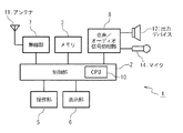
図面を参照して、本発明による音声出力装置の実施の形態を記載する。その音声出力装置は、携帯電話端末に適用されている。その携帯電話端末1は、図1に示されているように、制御部2とメモリ3と操作部5と表示部6と無線部7と音声/オーディオ信号処理部8とを備えている。制御部2は、CPU10を備え、携帯電話端末1にインストールされるコンピュータプログラムを実行して、メモリ3と操作部5と表示部6と無線部7と音声/オーディオ信号処理部8とを制御する。メモリ3は、そのコンピュータプログラムを記録し、制御部2により生成される情報を一時的に記録している。メモリ3は、さらに、音声データを記録している。操作部5は、複数のキーを備え、ユーザに操作されることにより情報を生成し、その情報を制御部4に出力する。表示部6は、制御部4により生成される画面を表示する。
Embodiments of an audio output device according to the present invention will be described with reference to the drawings. The audio output device is applied to a mobile phone terminal. As shown in FIG. 1, the
無線部7は、アンテナ11を備え、アンテナ11を用いて外部機器からの無線信号を受信し、その無線信号を受信情報に復調して制御部4に出力する。無線部7は、さらに、制御部4により生成された送信情報を無線信号に変調し、アンテナ11を用いてその無線信号を外部機器に送信する。その外部機器としては、携帯電話通信網に適用される基地局が例示される。 The radio unit 7 includes an antenna 11, receives a radio signal from an external device using the antenna 11, demodulates the radio signal into reception information, and outputs the received information to the control unit 4. The radio unit 7 further modulates the transmission information generated by the control unit 4 into a radio signal, and transmits the radio signal to an external device using the antenna 11. As the external device, a base station applied to a mobile phone communication network is exemplified.
音声/オーディオ信号処理部8は、出力デバイス12とマイク14とを備えている。音声/オーディオ信号処理部8は、マイク14により集音された音声を示す音声情報を生成して、その音声情報を制御部4に出力する。音声/オーディオ信号処理部8は、さらに、制御部4により制御されて、出力デバイス12を用いて音声を出力する。
The audio / audio
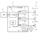
図2は、音声/オーディオ信号処理部8を示している。音声/オーディオ信号処理部8は、電源20と音源21とD/A(デジタル/アナログ)変換器22とレシーバアンプ23とスピーカアンプ24とイヤホンアンプ25とミュート回路29とセンサ30とを備えている。このとき、出力デバイス12は、レシーバ26とスピーカ27とイヤホン28とを含んでいる。
FIG. 2 shows the voice / audio
電源20は、制御部4により制御されて、オンにされ、または、オフにされる。電源20は、オンにされたときに、レシーバアンプ23とスピーカアンプ24とイヤホンアンプ25とに電力を供給する。電源20は、オフにされたときに、レシーバアンプ23とスピーカアンプ24とイヤホンアンプ25とに電力を供給することを停止する。電源20は、さらに、複数のモードを有し、制御部2により、その複数のモードのうちのいずれかに切り換えられる。その複数のモードは、通常モードと省電力モードとを含んでいる。電源20は、その通常モードに切り換えられたときに、レシーバアンプ23とスピーカアンプ24とイヤホンアンプ25とが正常に動作するように、レシーバアンプ23とスピーカアンプ24とイヤホンアンプ25とに電力を供給する。電源20は、その省電力モードに切り換えられたときに、急峻な電圧低下なしで、レシーバアンプ23とスピーカアンプ24とイヤホンアンプ25とに供給する電力を低減する。このとき、電源20は、通常モードで消費される電流に比較して、省電力モードで消費される電流がより小さく、たとえば、数μA程度である。
The
音源21は、音声を示すデジタル信号を生成する。たとえば、音源21は、音楽再生用のブロックであり、このとき、メモリ3から音声データを読み出し、その音声データをデジタル信号として出力する。また、音源21は、トーン生成回路などによって構成されることもできる。なお、音源21は、本実施の形態において制御部2の外に独立したブロックとして構成されているが、制御部2に再生用モジュールとして組み込まれることもできる。
The
D/A変換器22は、音源21により生成されたデジタル信号をアナログ信号に変換する。レシーバアンプ23は、電源20から供給される電力を用いて、D/A変換器22により変換されたアナログ信号を増幅して電気信号を生成し、その電気信号をレシーバ26に出力する。レシーバ26は、レシーバアンプ23から出力された電気信号を音声に変換して出力する。スピーカアンプ24は、電源20から供給される電力を用いて、D/A変換器22により変換されたアナログ信号を増幅して電気信号を生成し、その電気信号をスピーカ27に出力する。スピーカ27は、スピーカアンプ24から出力された電気信号を音声に変換して出力する。
The D /
イヤホンアンプ25は、電源20から供給される電力を用いて、D/A変換器22により変換されたアナログ信号を増幅して電気信号を生成し、その電気信号をイヤホン28に出力する。イヤホン28は、ユーザの操作により携帯電話端末1に着脱可能である。イヤホン28は、携帯電話端末1に挿入されているときに、イヤホンアンプ25から出力された電気信号を音声に変換して出力する。センサ30は、イヤホン28が携帯電話端末1に挿入されているか抜き出されているかを検出し、検出結果を制御部2に出力する。
The
ミュート回路29は、FET(Field−Effect Transistor)から形成されている。ミュート回路29は、制御部4により制御され、イヤホンアンプ25から出力された電気信号をイヤホン28に伝達する配線を接地させないで、または、その配線を接地させる。すなわち、ミュート回路29は、制御部4により制御され、イヤホン28から音声を出力するようにミュート解除し、または、イヤホン28から音声が出力されないようにミュートする。ミュート回路29は、電源20がオフにされたときに、その配線に急峻な電圧降下を発生させて、イヤホン28からプツ音を発生させる。
The
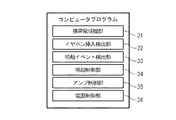
図3は、携帯電話端末1にインストールされるコンピュータプログラムを示している。そのコンピュータプログラムは、携帯電話機部31とイヤホン挿入検出部32と鳴動イベント検出部33と鳴動制御部34とアンプ制御部35と電源制御部36とを含んでいる。
FIG. 3 shows a computer program installed in the
携帯電話機部31は、携帯電話端末1を携帯電話機として機能させる。すなわち、携帯電話機部31は、操作部5に入力される所定の操作に応答して、無線部7を用いて、マイク14により収音された音声を他のコンピュータに携帯電話通信網を介して送信し、そのコンピュータから携帯電話通信網を介して受信された音声を出力デバイス12から出力する。携帯電話機部31は、さらに、操作部5に入力される所定の操作に応答して、無線部7を用いて、操作部5を介して作成された電子メールを他のコンピュータに送信し、そのコンピュータから受信された電子メールを表示部6に表示する。なお、その携帯電話通信網は、他の通信回線網に置換されることができる。その通信回線網としては、LAN(Local Area Network)、インターネット、専用回線が例示される。
The
イヤホン挿入検出部32は、センサ30を用いて、イヤホン28が携帯電話端末1に挿入されているか抜き出されているかを検出する。
The earphone
鳴動イベント検出部33は、鳴動イベントまたは鳴動オフイベントを検出する。その鳴動イベントは、出力デバイス12から音声を発生させるイベントを示している。その鳴動イベントとしては、操作部5のキーが押下されることが例示される。その鳴動オフイベントは、出力デバイス12から発生している音声を停止するイベントである。その鳴動オフイベントとしては、その音声が発生し始めてから所定の時間が経過したことが例示される。
The ringing
鳴動制御部34は、所定のタイミングで、イヤホン28から音声が出力されないようにミュート回路29を制御してミュートし、または、イヤホン28から音声が出力されるようにミュート回路29を制御してミュート解除する。
The ringing
アンプ制御部35は、所定のタイミングで、イヤホンアンプ25を起動し、または、イヤホンアンプ25を停止する。
The
電源制御部36は、所定のタイミングで、電源20をオンし、または、電源20をオフする。電源制御部36は、さらに、所定のタイミングで、電源20のモードを通常モードに設定し、または、電源20のモードを省電力モードに設定する。
The power
本発明によるノイズ防止策の実施の形態は、携帯電話端末1により実行され、携帯電話機としての動作と、鳴動に関するイベントが検出されたときの動作と、イヤホン28の抜差しが検出されたときの動作とを備えている。
The embodiment of the noise prevention measure according to the present invention is executed by the
その携帯電話機としての動作では、携帯電話端末1は、操作部5の所定のキーの押下に応答して、無線部7を用いて、マイク14により収音された音声を他のコンピュータに携帯電話通信網を介して送信し、そのコンピュータから携帯電話通信網を介して受信された音声を出力デバイス12から出力する。携帯電話端末1は、さらに、操作部5の所定のキーの押下に応答して、無線部7を用いて、操作部5を介して作成された電子メールを他のコンピュータに送信し、そのコンピュータから受信された電子メールを表示部6に表示する。
In the operation as the cellular phone, the
その鳴動に関するイベントが検出されたときの動作を以下に説明する。携帯電話端末1は、イヤホン28が挿入されている場合で、鳴動イベントが検出されたときに、ミュート回路29を用いてミュートし、電源20のモードを通常モードに切り替え、イヤホンアンプ25を起動させ、ミュート回路29を用いてミュート解除する。このような動作によれば、携帯電話端末1は、ミュート解除された後に、音源21により生成された音声をイヤホン28から出力する。
The operation when an event related to the ringing is detected will be described below. When the earphone 28 is inserted and a ringing event is detected, the
携帯電話端末1は、イヤホン28が抜かれている場合で、鳴動イベントが検出されたときに、ミュート回路29を用いてミュートし、電源20をオンにし、イヤホンアンプ25を起動させ、ミュート回路29を用いてミュート解除する。このような動作によれば、携帯電話端末1は、ミュート解除された後に、音源21により生成された音声をレシーバ26とスピーカ27とから出力する。
携帯電話端末1は、イヤホン28が挿入されている場合で、鳴動オフイベントが検出されたときに、ミュート回路29を用いてミュートし、電源20のモードを省電力モードに設定する。このような動作によれば、携帯電話端末1は、ミュートされた後に、音源21により生成された音声がイヤホン28から出力されることが防止される。
When the earphone 28 is removed and the ringing event is detected, the
When the earphone 28 is inserted and a ringing off event is detected, the
携帯電話端末1は、イヤホン28が抜かれている場合で、鳴動オフイベントが検出されたときに、電源20をオフにする。このような動作によれば、携帯電話端末1は、ミュートされた後に、音源21により生成された音声がレシーバ26とスピーカ27とから出力されることが防止される。
The
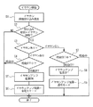
図4は、そのイヤホン28の抜差しが検出されたときの動作を示している。携帯電話端末1は、センサ30によりイヤホン28が挿入されたことが検出されたときに、または、イヤホン28が抜かれたことが検出されたときに、まず、割り込みを発生させる(ステップS1)。携帯電話端末1は、その割り込みの要因がイヤホン28の挿入または抜き出しであるときに(ステップS2、YES)、イヤホン28が挿入されたかイヤホン28が抜かれたかを判定する(ステップS3)。
FIG. 4 shows an operation when the insertion / removal of the earphone 28 is detected. When the
携帯電話端末1は、イヤホン28が挿入されたときに(ステップS3、イヤホンあり)鳴動中であるか否かを判定する(ステップS4)。携帯電話端末1は、鳴動中でないときに(ステップS4、鳴動OFF)、電源20をオンし(ステップS5)、電源20のモードを省電力モードに設定する(ステップS6)。
The
携帯電話端末1は、イヤホン28が抜かれたときに(ステップS3、イヤホンなし)、鳴動中であるか否かを判定する(ステップS7)。携帯電話端末1は、鳴動中でないときに(ステップS7、鳴動OFF)、電源20をオフし(ステップS8)、電源20のモードを通常モードに設定する(ステップS9)。
When the earphone 28 is removed (step S3, no earphone), the
このような動作は、イヤホン28に関する処理のみを変更し、イヤホン28以外の出力デバイス12(レシーバ26やスピーカ27)の鳴動処理については影響を与えない。 Such an operation changes only the process related to the earphone 28 and does not affect the sounding process of the output device 12 (receiver 26 or speaker 27) other than the earphone 28.
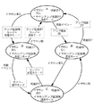
図5は、本発明の比較例による携帯電話機がとりうる状態を示している。その状態は、状態A〜状態Dを含んでいる。状態Aは、鳴動していないで、かつ、イヤホン28が挿入されていない状態である。電源20は、状態Aのときに、オフされており、モードが通常モードである。状態Bは、鳴動中であり、かつ、イヤホン28が挿入されていない状態である。電源20は、状態Bのときに、オンされており、モードが通常モードである。状態Cは、鳴動中であり、かつ、イヤホン28が挿入されている状態である。電源20は、状態Cのときに、オンされており、モードが通常モードである。状態Dは、鳴動していないで、かつ、イヤホン28が挿入されている状態である。電源20は、状態Dのときに、オフされており、モードが通常モードである。
FIG. 5 shows states that can be taken by the mobile phone according to the comparative example of the present invention. The state includes state A to state D. The state A is a state in which no sound is generated and the earphone 28 is not inserted. The
比較例の携帯電話端末は、状態Aで鳴動イベントが検出されたときに、電源20がオンされて状態Bへ遷移する。比較例の携帯電話端末は、状態Bで鳴動オフイベントが検出されたときに、電源20がオフされて状態Aへ遷移する。比較例の携帯電話端末は、状態Bでイヤホン28が挿入されたときに、状態Cへ遷移する。比較例の携帯電話端末は、状態Cでイヤホン28が抜かれたときに、状態Bへ遷移する。比較例の携帯電話端末は、状態Aでイヤホン28が挿入されたときに、状態Dへ遷移する。比較例の携帯電話端末は、状態Dでイヤホン28が抜かれたときに、状態Aへ遷移する。比較例の携帯電話端末は、状態Dで鳴動イベントが検出されたときに、電源20がオンされて状態Cへ遷移する。比較例の携帯電話端末は、状態Cで鳴動オフイベントが検出されたときに、電源20がオフされて状態Dへ遷移する。このとき、ミュート回路29によりイヤホン28に繋がる配線に急峻な電圧降下が発生して、イヤホン28からノイズが発生する。
When a ringing event is detected in the state A, the mobile phone terminal of the comparative example is turned on and makes a transition to the state B. When the ringing off event is detected in the state B, the
図6は、比較例の携帯電話端末における制御タイミングを示している。比較例の携帯電話端末は、鳴動していないで、かつ、イヤホン28が挿入されていない状態Aで、イヤホン28が挿入されたときに、電源20をオンしないでオフのままにしている。比較例の携帯電話端末は、鳴動イベントが検出されると、ミュート回路29を用いてミュートし、電源20をオンし、イヤホンアンプ25を起動させ、ミュート回路29を用いてミュート解除する。比較例の携帯電話端末は、ミュート解除されると、イヤホン28から音声を出力して鳴動中となる。
FIG. 6 shows the control timing in the mobile phone terminal of the comparative example. The mobile phone terminal of the comparative example is not ringing, and in the state A where the earphone 28 is not inserted, when the earphone 28 is inserted, the
比較例の携帯電話端末は、鳴動しているときに鳴動オフイベントが検出されると、ミュート回路29を用いてミュートし、イヤホンアンプ25を停止させる。比較例の携帯電話端末は、ミュートされると、イヤホン28から音声が出力されることを停止する。このようなミュートによれば、ボタン確認音を鳴動する場合のイヤホンアンプ25のオン時やパス切り替え時に発生するノイズを防ぐことができる。比較例の携帯電話端末は、鳴動オフイベントが検出されてから数秒(たとえば、10秒)経過後に、電源20をオフする。比較例の携帯電話端末は、イヤホン28が抜かれる前に電源20がオフされると、ミュート回路29によりイヤホン28に繋がる配線に急峻な電圧降下が発生して、イヤホン28からノイズが発生する。
When a ringing off event is detected while ringing, the mobile phone terminal of the comparative example mutes using the
音楽データを連続して再生する場合、鳴動中は鳴動終了処理が行われないため上記のノイズは目立たないが、特に、ボタン操作を行う際に鳴動するボタン確認音は、ボタン押す度に鳴動開始処理、鳴動終了処理を行うため、ノイズの発生がユーザに判りやすい。 When music data is played continuously, the above noise is inconspicuous because the ringing end process is not performed during ringing. In particular, the button confirmation sound that rings when a button is operated starts to ring each time the button is pressed. Since the processing and ringing end processing are performed, the occurrence of noise is easily understood by the user.
上記のノイズを防止すべく、イヤホン28が鳴動しない間も電源20をオンしたままにすることも考えられるが、その場合無駄な電流を消費してしまうことになり電池の消耗を早めてしまう。また、鳴動終了後からタイマーを使用して数秒(たとえば、10秒)後に電源20をオフすることで、ユーザにノイズ発生を分かりにくくさせている。このとき、その数秒後には、ノイズが発生してしまい恒久対策にはならない。また、タイマーを利用した場合、タイマー終了前にイヤホンを抜いてしまうとアンプの電源はオンされたままであるため無駄な電流を消費してしまう。
In order to prevent the above-mentioned noise, it is conceivable to keep the
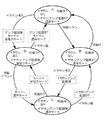
図7は、本発明による携帯電話機1がとりうる状態を示している。その状態は、既述の比較例の携帯電話端末と同様にして、状態A〜状態Dを含んでいる。状態Aは、鳴動していないで、かつ、イヤホン28が挿入されていない状態である。電源20は、状態Aのときに、オフされており、モードが通常モードである。状態Bは、鳴動中であり、かつ、イヤホン28が挿入されていない状態である。電源20は、状態Bのときに、オンされており、モードが通常モードである。状態Cは、鳴動中であり、かつ、イヤホン28が挿入されている状態である。電源20は、状態Cのときに、オンされており、モードが通常モードである。状態Dは、鳴動していないで、かつ、イヤホン28が挿入されている状態である。電源20は、状態Dのときに、オンされており、モードが省電力モードである。
FIG. 7 shows states that the
携帯電話端末1は、状態Aで鳴動イベントが検出されたときに、電源20がオンされて状態Bへ遷移する。携帯電話端末1は、状態Bで鳴動オフイベントが検出されたときに、電源20がオフされて状態Aへ遷移する。携帯電話端末1は、状態Bでイヤホン28が挿入されたときに、状態Cへ遷移する。携帯電話端末1は、状態Cでイヤホン28が抜かれたときに、状態Bへ遷移する。携帯電話端末1は、状態Aでイヤホン28が挿入されたときに、電源20がオンされて、電源20のモードが省電力モードに設定されて、状態Dへ遷移する。携帯電話端末1は、状態Dでイヤホン28が抜かれたときに、電源20のモードが省電力モードに設定されて、電源20がオンされて、状態Aへ遷移する。携帯電話端末1は、状態Dで鳴動イベントが検出されたときに、電源20のモードが通常モードに設定されて状態Cへ遷移する。携帯電話端末1は、状態Cで鳴動オフイベントが検出されたときに、電源20のモードが省電力モードに設定されて状態Dへ遷移する。このとき、ミュート回路29によりイヤホン28に繋がる配線に急峻な電圧降下が発生しないで、イヤホン28からノイズが発生しない。
When a ringing event is detected in the state A, the
このような状態の遷移は、イヤホンに関する処理(状態Aと状態Dとの遷移、状態Cと状態Dとの遷移)のみを変更し、イヤホン28以外の出力デバイス12(レシーバ26やスピーカ27)の鳴動処理(状態Aと状態Bとの遷移、状態Bと状態Cとの遷移)については影響を与えない。すなわち、携帯電話端末1は、イヤホン28を抜くときの電源20のオフと同時に電源20のモードを通常モードに設定しておくことで、イヤホン28以外のレシーバ26やスピーカ27の処理については従来からの変更が不要となり、好ましい。
Such state transition changes only the processing related to the earphone (transition between state A and state D, transition between state C and state D), and the
このような遷移によれば、携帯電話端末1は、鳴動していないで、かつ、イヤホン28が挿入されている状態Dで、電源20が省電力モードであり、無駄な電流が消費されてしまうことが防止され、電池の消耗を早めてしまうことを防止することができる。
According to such a transition, the
図8は、携帯電話端末1における制御タイミングを示している。携帯電話端末1は、鳴動していないで、かつ、イヤホン28が挿入されていない状態で、イヤホン28が挿入されたときに、電源20をオンし、電源20のモードを省電力モードに設定する。携帯電話端末1は、鳴動イベントが検出されると、ミュート回路29を用いてミュートし、電源20のモードを通常モードに設定し、イヤホンアンプ25を起動させ、ミュート回路29を用いてミュート解除する。携帯電話端末1は、ミュート解除されると、イヤホン28から音声を出力して鳴動中となる。
FIG. 8 shows the control timing in the
携帯電話端末1は、鳴動しているときに鳴動オフイベントが検出されると、ミュート回路29を用いてミュートし、イヤホンアンプ25を停止させる。携帯電話端末1は、ミュートされると、イヤホン28から音声が出力されることを停止する。携帯電話端末1は、ミュートされた後に、電源20のモードを省電力モードに設定する。携帯電話端末1は、イヤホン28が抜かれた後に、電源20をオフする。携帯電話端末1は、このようにイヤホン28が抜かれた後に電源20がオフされると、ミュート回路29によりイヤホン28に繋がる配線に急峻な電圧降下が発生しないで、イヤホン28からノイズが発生しない。
When the ringing off event is detected while ringing, the
本発明によるノイズ防止策の実施の他の形態は、既述の実施の形態におけるノイズ防止策が他の処理に置換されている。 In another embodiment of the noise prevention measure according to the present invention, the noise prevention measure in the above-described embodiment is replaced with another process.
図9は、このようなノイズ防止策を実行する携帯電話機1がとりうる状態を示している。その状態は、既述の比較例の携帯電話端末と同様にして、状態A〜状態Dを含んでいる。状態Aは、鳴動していないで、かつ、イヤホン28が挿入されていない状態である。電源20は、状態Aのときに、オフされており、モードが通常モードである。状態Bは、鳴動中であり、かつ、イヤホン28が挿入されていない状態である。電源20は、状態Bのときに、オフされており、モードが通常モードである。状態Cは、鳴動中であり、かつ、イヤホン28が挿入されている状態である。電源20は、状態Cのときに、オンされており、モードが通常モードである。状態Dは、鳴動していないで、かつ、イヤホン28が挿入されている状態である。電源20は、状態Dのときに、オンされており、モードが省電力モードである。
FIG. 9 shows a state that the
携帯電話端末1は、状態Aで鳴動イベントが検出されたときに、状態Bへ遷移する。携帯電話端末1は、状態Bで鳴動オフイベントが検出されたときに、状態Aへ遷移する。携帯電話端末1は、状態Bでイヤホン28が挿入されたときに、電源20がオンされて状態Cへ遷移する。携帯電話端末1は、状態Cでイヤホン28が抜かれたときに、電源20がオフされて状態Bへ遷移する。携帯電話端末1は、状態Aでイヤホン28が挿入されたときに、電源20がオンされて、電源20のモードが省電力モードに設定されて、状態Dへ遷移する。携帯電話端末1は、状態Dでイヤホン28が抜かれたときに、電源20のモードが省電力モードに設定されて、電源20がオンされて、状態Aへ遷移する。携帯電話端末1は、状態Dで鳴動イベントが検出されたときに、電源20のモードが通常モードに設定されて状態Cへ遷移する。携帯電話端末1は、状態Cで鳴動オフイベントが検出されたときに、電源20のモードが省電力モードに設定されて状態Dへ遷移する。このとき、携帯電話端末1は、状態Bで出力デバイス12から音声が出力されないが、既述の実施の形態におけるノイズ防止策と同様にして、ミュート回路29によりイヤホン28に繋がる配線に急峻な電圧降下が発生しないで、イヤホン28からノイズが発生しない。 When the ringing event is detected in the state A, the mobile phone terminal 1 transits to the state B. When the ringing off event is detected in the state B, the mobile phone terminal 1 transitions to the state A. When the earphone 28 is inserted in the state B, the mobile phone terminal 1 is turned on and changes to the state C. When the earphone 28 is pulled out in the state C, the mobile phone terminal 1 is turned off and the state transitions to the state B. When the earphone 28 is inserted in the state A, the cellular phone terminal 1 is turned on, the mode of the power source 20 is set to the power saving mode, and the state transitions to the state D. When the earphone 28 is pulled out in the state D, the cellular phone terminal 1 is set to the power saving mode, the power source 20 is turned on, and the state transitions to the state A. When a ringing event is detected in the state D, the cellular phone terminal 1 is set to the normal mode in the power source 20 and transitions to the state C. When the ringing off event is detected in the state C, the mobile phone terminal 1 is set to the power saving mode and transitions to the state D. At this time, the mobile phone terminal 1 does not output sound from the output device 12 in the state B, but a steep voltage is applied to the wiring connected to the earphone 28 by the mute circuit 29 in the same manner as the noise prevention measure in the above-described embodiment. No descent occurs and no noise is generated from the earphone 28.
イヤホン28が挿入されていない状態でボタン確認音を鳴動させる場合、状態Aから状態Bへ遷移するが、レシーバ26やスピーカ27を鳴動する際には電源20はオンされない。よって状態Bから状態Aの鳴動終了時も電源20のオフ処理は不要となる。逆に、状態Bから状態Cへ遷移する際(たとえば、ボタン確認音鳴動中にイヤホン28挿入)には、電源20をこのタイミングでオンする必要がある。また、状態Cのイヤホン28鳴動中にイヤホン28を抜いたときには状態Cから状態Bへ遷移するタイミングでアンプ電源20がオフされる。
When the button confirmation sound is sounded in a state where the earphone 28 is not inserted, the state A is changed to the state B, but the
このような遷移によれば、携帯電話端末1は、鳴動していないで、かつ、イヤホン28が挿入されている状態Dで、電源20が省電力モードであり、無駄な電流が消費されてしまうことが防止され、電池の消耗を早めてしまうことを防止することができる。
According to such a transition, the
なお、携帯電話端末1は、電源20として省電力モードがない電源を適用することもできる。このとき、携帯電話端末1は、無駄な電流を消費してしまうことになり電池の消耗を早めてしまうが、イヤホン28から発生するノイズを防止することができる。
Note that the
1 :携帯電話端末
2 :制御部
3 :メモリ
4 :制御部
5 :操作部
6 :表示部
7 :無線部
8 :音声/オーディオ信号処理部
11:アンテナ
12:出力デバイス
14:マイク
20:電源
21:音源
22:D/A変換器
23:レシーバアンプ
24:スピーカアンプ
25:イヤホンアンプ
26:レシーバ
27:スピーカ
28:イヤホン
30:センサ
31:携帯電話機部
32:イヤホン挿入検出部
33:鳴動イベント検出部
34:鳴動制御部
35:アンプ制御部
36:電源制御部
DESCRIPTION OF SYMBOLS 1: Cellular phone terminal 2: Control part 3: Memory 4: Control part 5: Operation part 6: Display part 7: Radio | wireless part 8: Audio | voice / audio signal processing part 11: Antenna 12: Output device 14: Microphone 20: Power supply 21 : Sound source 22: D / A converter 23: Receiver amplifier 24: Speaker amplifier 25: Earphone amplifier 26: Receiver 27: Speaker 28: Earphone 30: Sensor 31: Mobile phone unit 32: Earphone insertion detection unit 33: Ring event detection unit 34: Ring control unit 35: Amplifier control unit 36: Power supply control unit
Claims (12)
前記イヤホンが抜かれたことを検出した後に、前記電気信号を生成するための電力を前記イヤホンアンプに供給する電源をオフにする電源制御部と、
鳴動イベントまたは鳴動オフイベントを検出する鳴動イベント検出部
とを具備し、
前記電源制御部は、前記イヤホンが挿入され、かつ、前記鳴動オフイベントが検出された後に、前記電力が低減するように前記電源を制御する
音声出力装置。 An earphone insertion detection unit that detects whether or not an earphone that converts an electrical signal generated by the earphone amplifier into sound is removed using a sensor;
A power control unit that turns off a power source that supplies power for generating the electrical signal to the earphone amplifier after detecting that the earphone has been removed;
A ring event detector that detects a ring event or ring off event,
The power supply control unit controls the power supply so that the power is reduced after the earphone is inserted and the ringing off event is detected.
前記電源制御部は、前記イヤホンが抜かれ、または、前記鳴動イベントが検出された後に、前記電力が前記イヤホンアンプに供給されるように前記電源を制御する
音声出力装置。 In claim 1,
The power supply control unit controls the power supply so that the power is supplied to the earphone amplifier after the earphone is removed or the ringing event is detected.
前記電源制御部は、前記イヤホンが抜かれ、かつ、前記鳴動オフイベントが検出された後に、前記電源をオフにし、前記イヤホンが抜かれ、かつ、前記鳴動イベントが検出された後に、前記電源をオンにする
音声出力装置。 In either claim 1 or claim 2,
The power control unit turns off the power after the earphone is unplugged and the ringing off event is detected, and turns on the power after the earphone is unplugged and the ringing event is detected. Sound output device.
前記電源制御部は、前記鳴動イベントが検出され、かつ、前記イヤホンが抜かれた後に、前記電源をオフにし、前記鳴動イベントが検出され、かつ、前記イヤホンが挿入された後に、前記電源をオンにする
音声出力装置。 In either claim 1 or claim 2,
The power control unit turns off the power after the ringing event is detected and the earphone is removed, and turns on the power after the ringing event is detected and the earphone is inserted. Sound output device.
前記イヤホンが抜かれたことを検出した後に、前記電気信号を生成するための電力を前記イヤホンアンプに供給する電源をオフにするステップと、
鳴動イベントまたは鳴動オフイベントを検出するステップと、
前記イヤホンが挿入され、かつ、前記鳴動オフイベントが検出された後に、前記電力が低減するように前記電源を制御するステップ
とを具備するノイズ防止方法。 Detecting whether an earphone for converting an electrical signal generated by the earphone amplifier into sound is removed using a sensor;
After detecting that the earphone has been removed, turning off a power source for supplying power to generate the electrical signal to the earphone amplifier;
Detecting a ringing event or ringing off event;
And a step of controlling the power supply so that the power is reduced after the earphone is inserted and the ring-off event is detected.
前記イヤホンが抜かれ、または、前記鳴動イベントが検出された後に、前記電力が前記イヤホンアンプに供給されるように前記電源を制御するステップ
を更に具備するノイズ防止方法。 In claim 5,
The noise prevention method further comprising the step of controlling the power supply so that the power is supplied to the earphone amplifier after the earphone is unplugged or the ringing event is detected.
前記イヤホンが抜かれ、かつ、前記鳴動オフイベントが検出された後に、前記電源をオフにするステップと、
前記イヤホンが抜かれ、かつ、前記鳴動イベントが検出された後に、前記電源をオンにするステップ
とを更に具備するノイズ防止方法。 In either claim 5 or claim 6,
Turning off the power after the earphone is unplugged and the ring off event is detected;
A method for preventing noise, further comprising: turning on the power after the earphone is unplugged and the ringing event is detected.
前記鳴動イベントが検出され、かつ、前記イヤホンが抜かれた後に、前記電源をオフにするステップと、
前記鳴動イベントが検出され、かつ、前記イヤホンが挿入された後に、前記電源をオンにするステップ
とを更に具備するノイズ防止方法。 In either claim 5 or claim 6,
Turning off the power after the ringing event is detected and the earphone is removed;
A noise prevention method further comprising: turning on the power after the ringing event is detected and the earphone is inserted.
前記イヤホンが抜かれたことを検出した後に、前記電気信号を生成するための電力を前記イヤホンアンプに供給する電源をオフにする電源制御機能と、
鳴動イベントまたは鳴動オフイベントを検出する鳴動イベント検出機能
とをコンピュータに実現させるためのコンピュータプログラムであって、
前記電源制御機能は、前記イヤホンが挿入され、かつ、前記鳴動オフイベントが検出された後に、前記電力が低減するように前記電源を制御する
コンピュータプログラム。 An earphone detection function for detecting whether or not an earphone for converting an electrical signal generated by an earphone amplifier into sound using a sensor has been removed;
A power control function for turning off a power supply for supplying power for generating the electrical signal to the earphone amplifier after detecting that the earphone is removed;
A computer program for causing a computer to perform a ringing event detection function for detecting a ringing event or a ringing off event,
The power control function, the earphone is inserted, and, after the ringing off event is detected, the computer program the power to control the power supply so as to reduce.
前記電源制御機能は、前記イヤホンが抜かれ、または、前記鳴動イベントが検出された後に、前記電力が前記イヤホンアンプに供給されるように前記電源を制御する
コンピュータプログラム。 In claim 9,
The power control function, the earphone is pulled out, or after the ringing event is detected, the computer program the power to control the power to be supplied to the earphone amplifier.
前記電源制御機能は、前記イヤホンが抜かれ、かつ、前記鳴動オフイベントが検出された後に、前記電源をオフにし、前記イヤホンが抜かれ、かつ、前記鳴動イベントが検出された後に、前記電源をオンにする
コンピュータプログラム。 In either claim 9 or claim 10,
The power control function turns off the power after the earphone is unplugged and the ringing off event is detected, and turns on the power after the earphone is unplugged and the ringing event is detected. Computer program.
前記電源制御機能は、前記鳴動イベントが検出され、かつ、前記イヤホンが抜かれた後に、前記電源をオフにし、前記鳴動イベントが検出され、かつ、前記イヤホンが挿入された後に、前記電源をオンにする
コンピュータプログラム。 In either claim 9 or claim 10,
The power control function turns off the power after the ringing event is detected and the earphone is removed, and turns on the power after the ringing event is detected and the earphone is inserted. Computer program.
Priority Applications (1)
| Application Number | Priority Date | Filing Date | Title |
|---|---|---|---|
| JP2007337081A JP5211684B2 (en) | 2007-12-27 | 2007-12-27 | Audio output device and noise prevention method |
Applications Claiming Priority (1)
| Application Number | Priority Date | Filing Date | Title |
|---|---|---|---|
| JP2007337081A JP5211684B2 (en) | 2007-12-27 | 2007-12-27 | Audio output device and noise prevention method |
Publications (2)
| Publication Number | Publication Date |
|---|---|
| JP2009159441A JP2009159441A (en) | 2009-07-16 |
| JP5211684B2 true JP5211684B2 (en) | 2013-06-12 |
Family
ID=40962920
Family Applications (1)
| Application Number | Title | Priority Date | Filing Date |
|---|---|---|---|
| JP2007337081A Expired - Fee Related JP5211684B2 (en) | 2007-12-27 | 2007-12-27 | Audio output device and noise prevention method |
Country Status (1)
| Country | Link |
|---|---|
| JP (1) | JP5211684B2 (en) |
Families Citing this family (6)
| Publication number | Priority date | Publication date | Assignee | Title |
|---|---|---|---|---|
| JP2012169828A (en) | 2011-02-14 | 2012-09-06 | Sony Corp | Sound signal output apparatus, speaker apparatus, sound signal output method |
| JP2012169839A (en) | 2011-02-14 | 2012-09-06 | Sony Corp | Sound signal output apparatus and sound signal output method |
| KR102111708B1 (en) | 2014-01-10 | 2020-06-08 | 삼성전자주식회사 | Apparatus and method for reducing power consuption in hearing aid |
| JP2018006837A (en) * | 2016-06-27 | 2018-01-11 | リコーイメージング株式会社 | Connection apparatus discrimination device and optical apparatus |
| CN110677755A (en) * | 2018-07-02 | 2020-01-10 | 深圳市三诺数字科技有限公司 | Earphone output mute circuit and earphone |
| CN112822001B (en) * | 2020-12-31 | 2023-03-14 | 维沃移动通信有限公司 | Control method of electronic equipment and electronic equipment |
Family Cites Families (1)
| Publication number | Priority date | Publication date | Assignee | Title |
|---|---|---|---|---|
| JPS6057237U (en) * | 1983-09-26 | 1985-04-22 | 日本電気株式会社 | audio equipment |
-
2007
- 2007-12-27 JP JP2007337081A patent/JP5211684B2/en not_active Expired - Fee Related
Also Published As
| Publication number | Publication date |
|---|---|
| JP2009159441A (en) | 2009-07-16 |
Similar Documents
| Publication | Publication Date | Title |
|---|---|---|
| JP4317834B2 (en) | Sound output device and sound output control program | |
| JP5211684B2 (en) | Audio output device and noise prevention method | |
| US20030087679A1 (en) | Mobile telephone | |
| JP2007165940A (en) | Cellular phone, and acoustic reproduction operation automatic stopping method therefor | |
| US20050255817A1 (en) | Method and device for background monitoring of an audio source | |
| KR20060109770A (en) | Sound output control method for audio device | |
| JP2009224911A (en) | Headphone | |
| JP2005318267A (en) | Electronic equipment | |
| JP2003264885A (en) | Headphone output controller and mobile phone using the same | |
| JP2007013443A (en) | Electronic equipment and power saving control method | |
| KR100330850B1 (en) | Tv telephone and method for listening tv audio signal by close folder cover | |
| JP3661085B2 (en) | Mail reception notification system and mail reception notification method | |
| JP2002314633A (en) | Portable terminal device | |
| JP2011139232A (en) | Electric apparatus | |
| JPH10336049A (en) | House-wise radio receiver for preventing disaster | |
| JPH1188979A (en) | Sound reproduction device | |
| JP3425970B2 (en) | Small radio | |
| KR200194131Y1 (en) | MP3 Player Combined Radio Language Receiver | |
| JP2003289378A (en) | Portable telephone system with music reproduction function | |
| KR200279855Y1 (en) | Transmitter apparatus for wireless output a music data and voice data | |
| KR20050014243A (en) | Audio data playing appratus and method using the mobile station | |
| JP2982217B2 (en) | Wireless selective call receiver with audible sound reproduction function | |
| KR19990014640A (en) | Wireless telephone incoming call detection method and system | |
| JP5979050B2 (en) | Wireless communication device | |
| KR100469853B1 (en) | Necklace antenna of television mobile telephone comprising charging equipment |
Legal Events
| Date | Code | Title | Description |
|---|---|---|---|
| A711 | Notification of change in applicant |
Free format text: JAPANESE INTERMEDIATE CODE: A711 Effective date: 20100408 |
|
| A621 | Written request for application examination |
Free format text: JAPANESE INTERMEDIATE CODE: A621 Effective date: 20101115 |
|
| A131 | Notification of reasons for refusal |
Free format text: JAPANESE INTERMEDIATE CODE: A131 Effective date: 20120410 |
|
| A521 | Request for written amendment filed |
Free format text: JAPANESE INTERMEDIATE CODE: A523 Effective date: 20120604 |
|
| A131 | Notification of reasons for refusal |
Free format text: JAPANESE INTERMEDIATE CODE: A131 Effective date: 20121109 |
|
| A521 | Request for written amendment filed |
Free format text: JAPANESE INTERMEDIATE CODE: A523 Effective date: 20130108 |
|
| TRDD | Decision of grant or rejection written | ||
| A01 | Written decision to grant a patent or to grant a registration (utility model) |
Free format text: JAPANESE INTERMEDIATE CODE: A01 Effective date: 20130129 |
|
| A61 | First payment of annual fees (during grant procedure) |
Free format text: JAPANESE INTERMEDIATE CODE: A61 Effective date: 20130211 |
|
| R150 | Certificate of patent or registration of utility model |
Free format text: JAPANESE INTERMEDIATE CODE: R150 |
|
| FPAY | Renewal fee payment (event date is renewal date of database) |
Free format text: PAYMENT UNTIL: 20160308 Year of fee payment: 3 |
|
| S111 | Request for change of ownership or part of ownership |
Free format text: JAPANESE INTERMEDIATE CODE: R313113 |
|
| R350 | Written notification of registration of transfer |
Free format text: JAPANESE INTERMEDIATE CODE: R350 |
|
| R250 | Receipt of annual fees |
Free format text: JAPANESE INTERMEDIATE CODE: R250 |
|
| LAPS | Cancellation because of no payment of annual fees |
