JP5211368B2 - Image editing method and image editing apparatus - Google Patents
Image editing method and image editing apparatus Download PDFInfo
- Publication number
- JP5211368B2 JP5211368B2 JP2011129648A JP2011129648A JP5211368B2 JP 5211368 B2 JP5211368 B2 JP 5211368B2 JP 2011129648 A JP2011129648 A JP 2011129648A JP 2011129648 A JP2011129648 A JP 2011129648A JP 5211368 B2 JP5211368 B2 JP 5211368B2
- Authority
- JP
- Japan
- Prior art keywords
- image
- display
- layer
- exploded perspective
- moving image
- Prior art date
- Legal status (The legal status is an assumption and is not a legal conclusion. Google has not performed a legal analysis and makes no representation as to the accuracy of the status listed.)
- Expired - Fee Related
Links
Images


Landscapes
- Processing Or Creating Images (AREA)
Description
本発明は、画像編集方法及び画像編集装置に関し、特に、各種画像データを個別独立的に作成した複数(レイヤー)の重なりで構成された全体画像の編集を行う画像編集方法及び画像編集装置に関する。 The present invention relates to an image editing method and an image editing apparatus , and more particularly, to an image editing method and an image editing apparatus for editing an entire image composed of a plurality of (layers) created independently of various image data.
近年、ゲーム機やパチンコ機等の遊技機においては、静止画像や動画像などの画像が複雑なものとなっており、そのため画像データをレイヤーでそれぞれ作成し、これら複数のレイヤーの重なりで全体画像を構成することが行われている。 In recent years, game machines such as game machines and pachinko machines have complicated images such as still images and moving images. Therefore, image data is created in layers, and the entire image is created by overlapping these multiple layers. Has been made up.
従来、この種全体画像を編集するには、個々のレイヤーを個別に編集すればよいとの考えであったが、重ね合わせた状態で従来の方法で表示装置に表示した場合、各レイヤー相互の関係が画面上では把握しづらいために、全体画像の修正などの編集作業を行うことが困難であるので、どのレイヤーの画像を修正すると全体画像が所望のものになるかの認識ができないために、経験的な予測の元で編集作業を行わざるを得ないので、編集作業に要する効率が悪かった。 Conventionally, it was thought that it would be sufficient to edit individual layers individually to edit this whole image, but when displayed on a display device in a conventional manner in a superimposed state, each layer Since it is difficult to grasp the relationship on the screen, it is difficult to perform editing operations such as correction of the entire image, so it is not possible to recognize which layer image will become the desired one when the image is corrected Since the editing work must be performed based on empirical predictions, the efficiency required for the editing work was poor.
また、パチンコ機等の遊技機の場合、より遊興性を高めるために、上述の各レイヤーが、複雑に絡み合い、また短時間で劇的に変化するようなものが多いために、動画の場合には、個々のレイヤーの画像が短いタイミングで変化しているので、どのタイミングの画像を修正したら所望の全体画像が作れるのかなどの編集を行うことが困難になっていた。そのような複雑な全体画像の例としては、例えば、a)背景、b)ルーレット数字の移動・回転、c)瞬時の新たに現れる移動物体(例えば、斜め方向からルーレット数字にめがけて飛来してくるミサイルのようなものなど)の画像を各レイヤーに割り当てられる場合がある。このような場合でも、従来は、画像の作成、及び修正などの編集作業は、各レイヤーごとに行い、全体画像の確認は、重ね合わせ表示することで初めて行われることになっていた。 In the case of pachinko machines and other gaming machines, the above-mentioned layers are intricately entangled and often change dramatically in a short time to increase the playability. Since images of individual layers change at a short timing, it has been difficult to perform editing such as which timing image can be corrected to create a desired whole image. Examples of such complex whole images include, for example, a) background, b) movement / rotation of roulette numerals, c) a new object that appears instantaneously (for example, flying from a diagonal direction toward roulette numerals) You may be able to assign images to each layer. Even in such a case, conventionally, editing operations such as image creation and correction are performed for each layer, and confirmation of the entire image is performed for the first time by displaying the images in a superimposed manner.
しかしながら、画像の全体像は、重ね合わせて初めて分かるものであり、所望の画像となっていない場合がある。特に、複雑で変化が激しく、時間的なタイミングによって微妙に画像が変化するような厳格性が要求される画像であればあるほど、各レイヤーの画像の重ね合わせで、早期に所望の画像を得ることは殆ど不可能に近い。例えば、突然飛来するような移動物体(例えばミサイルのような画像)が回転しているルーレットの数字に衝突する瞬間を背景画像とともに描く場合には、ミサイルの飛来状態を動画表示するレイヤー、ルーレット数字を回転させるレイヤー、そして時間タイミングで変化する背景画像を示すレイヤーなどを重ね合わせた1つの全体画像が動画として表示される場合には、完成した全体画像が所望のものでなかった場合に、或る画素の変化が一つのレイヤーだけの問題なのか、他のレイヤーも含んだ複数のレイヤーの重ね合わせによりもたらされたのか分からない場合もある。 However, the entire image can be understood only after being superimposed, and may not be a desired image. In particular, the more complex and drastic changes that are required to be so strict that the image changes slightly depending on the timing in time, the earlier the desired image is obtained by superimposing the images of each layer. It is almost impossible. For example, when drawing a moment when a moving object (such as a missile-like image) that suddenly flies collides with a rotating roulette number with a background image, a layer that displays the missile's flying state, a roulette number If the entire image is displayed as a moving image with the layer that rotates the layer and the layer showing the background image that changes with time, etc., if the completed entire image is not what you want, or In some cases, it may not be clear whether the pixel change is a problem of only one layer or is caused by the superposition of multiple layers including other layers.
従って、このような場合、再びレイヤーごとの画像の修正作業(従来においては、レイヤーごとに別々に再生したり、不要なレイヤーを一時的に非表示状態とする)となるが、かかる形態では、前述のように全てのレイヤーを重ね合わせた状態でしか確認できないため、確認と修正の試行錯誤を繰り返すことが必要となる。また、従来においては、画像の修正はレイヤー単位で個別に行うので、任意のレイヤーの画像を修正しているときに、重ね合わせられる他のレイヤーの画像がどのような状態なのかなどの相関関係を把握することができなかった。 Therefore, in such a case, the image is corrected again for each layer (in the past, playback is performed separately for each layer or unnecessary layers are temporarily hidden). As described above, since it can be confirmed only when all the layers are overlaid, it is necessary to repeat trial and error for confirmation and correction. Also, in the past, image correction is performed individually on a layer-by-layer basis, so when modifying an image of an arbitrary layer, correlations such as the state of the image of another layer to be overlaid Could not figure out.
更に、動画像の場合には、時間軸上でのタイミング合わせも必要であるが、修正する必要があっても、どのタイミングでいずれのレイヤーの画像を修正すればよいのかすら判別ないし選択することは容易ではなかった。特に、遊興性をいっそう高めるために、レイヤーの数がより多くなる傾向にある現状においては、その編集作業にかかる工数は極めて甚大となっていた。 Furthermore, in the case of moving images, timing adjustment on the time axis is also necessary, but even if correction is necessary, it is even possible to determine or select which layer image should be corrected at which timing. Was not easy. In particular, in the current situation where the number of layers tends to increase in order to further enhance the playability, the man-hours required for the editing work are extremely large.
本発明は上述のような事情から為されたものであり、本発明の目的は、複数のレイヤーの重なりで構成された画像の編集の際に、各レイヤーにおける各画像の重なり具合を容易に認識できるように表示することにより、編集すべき画像を容易に選択できると共に、重なり合わせられる他の画像との相関関係及び、編集すべき画像と同じタイミングで表示される他のレイヤーの画像他の画像との関係を把握でき、ひいては全体画像の編集を容易に短時間で行える画像編集方法及び画像編集装置を提供することにある。 The present invention has been made for the above-mentioned circumstances, and an object of the present invention is to easily recognize the overlapping state of each image in each layer when editing an image composed of a plurality of overlapping layers. By displaying as possible, the image to be edited can be easily selected, the correlation with other images to be superimposed, and the image of other layers displayed at the same timing as the image to be edited It is therefore an object to provide an image editing method and an image editing apparatus capable of grasping the relationship between the image and the total image, and by which the entire image can be easily edited in a short time.
上記目的を達成するため、本発明の画像編集方法は、それぞれが独立の動画像データを含む複数のレイヤーで構成された動画像が格納される格納手段と、前記動画像の情報に対して処理を行う制御部と、前記動画像が表示されるディスプレイ装置と、を備えた画像編集装置における画像編集方法であって、a)前記ディスプレイ装置に表示された動画像に対して分解斜視表示指示手段を介して入力された指示に応じて、分解斜視表示手段により各レイヤーを分解斜視表示するステップと、b)前記ディスプレイ装置に分解斜視表示された動画像を時間的に推移させるステップと、c)前記ディスプレイ装置に分解斜視表示された動画像について、回転指示手段、距離変更指示手段、及びズーム変更指示手段を介して入力された各指示に応じて、注視点変更手段により任意に設定できる注目する画像点たる注視点を中心として画像回転手段により回転させる操作、レイヤー間距離変更手段により前記注視点を中心として各レイヤーを接近/離反させる操作、及びズーム変更手段により前記注視点を中心としてズームイン/アウトさせる操作のうちの少なくとも1つを行うことにより、各レイヤーの相互の関係を容易に把握できるようにするステップと、d)前記ステップb)及び前記ステップc)を任意に繰り返して不本意な動画像の表出の要因となっているレイヤーを探索し、選択指示手段を介して選択するステップと、e)前記選択されたレイヤーに係る画像を、前記制御部上で機能する画像編集手段により編集するステップと、を備えることを特徴とする。 In order to achieve the above object, the image editing method of the present invention is a storage means for storing a moving image composed of a plurality of layers each including independent moving image data, and processes the information of the moving image. An image editing method in an image editing apparatus comprising: a control unit that performs a display; and a display device on which the moving image is displayed, comprising : a) an exploded perspective display instruction unit for a moving image displayed on the display device A step of disassembling and displaying each layer by the disassembled perspective display means in response to an instruction inputted via b), b) a step of temporally shifting the moving image displayed in the exploded perspective view on the display device, and c) For the moving image displayed in an exploded perspective view on the display device, in accordance with each instruction input via the rotation instruction means, the distance change instruction means, and the zoom change instruction means , An operation of rotating by an image rotating unit around a gazing point as an image point of interest that can be arbitrarily set by the gazing point changing unit, an operation of approaching / separating each layer around the gazing point by an inter-layer distance changing unit, and Performing at least one of operations for zooming in / out with the gazing point as a center by zoom changing means, so that the mutual relationship between the layers can be easily grasped; and d) the step b) and Step c) is arbitrarily repeated to search for a layer that is a cause of unintentional moving image expression, and is selected through a selection instruction unit. E) An image related to the selected layer is selected. And a step of editing by an image editing means functioning on the control unit .
ここで、好適には、前記ステップb)において、前記推移先の時点は、前記不本意な動画像の表出時点の近傍である。 Here, preferably, in step b), the transition destination time point is in the vicinity of the unintentional moving image display time point .
また好適には、前記ステップe)において、選択されていないレイヤーに係る画像を含む全体画像を確認しながら、前記選択されたレイヤーに係る画像を前記画像編集手段により修正する。あるいは、前記ステップe)において、選択されていないレイヤーに係る画像を含む全体画像を確認しながら、前記選択されたレイヤーに係る画像の時間変化率を、前記ステップb)を併用しつつ前記画像編集手段により修正する。 Preferably, in the step e), the image editing unit corrects the image related to the selected layer while checking the entire image including the image related to the unselected layer . Alternatively, in the step e), while confirming the entire image including the image related to the unselected layer, the time change rate of the image related to the selected layer is used together with the step b) to edit the image. Correct by means .
また、好適には、前記ステップe)の後、前記分解斜視表示手段により前記分解斜視表示を終了して各レイヤーが重ね合わさった通常表示に戻すステップf)を更に備える。 Preferably, after the step e), the apparatus further comprises a step f) of ending the exploded perspective display by the exploded perspective display means and returning to the normal display in which the layers are overlaid .
また、好適には、前記ステップa)において、まず斜視表示し、次いで分解表示する。このとき、前記ステップa)において、斜視表示前の表示から、前記斜視表示を経て、前記分解表示まで、連続的に滑らかに行う。また、このとき、前記分解斜視表示は、各レイヤーの2次元画像を3次元ポリゴンとそのテクスチャデータとして再構成することにより行う。 Preferably, in step a), a perspective view is first displayed and then an exploded display is performed . At this time, in the step a), the display is continuously and smoothly performed from the display before the perspective display to the disassembled display through the perspective display . At this time, the exploded perspective display is performed by reconstructing the two-dimensional image of each layer as a three-dimensional polygon and its texture data.
また、好適には、前記動画像は、遊技機に表示される動画像である。 Preferably, the moving image is a moving image displayed on a gaming machine .
また、上記目的を達成するため、本発明の画像編集装置は、それぞれが独立の動画像データを含む複数のレイヤーで構成された動画像が格納される格納手段と、前記動画像の情報に対して処理を行う制御部と、前記動画像が表示されるディスプレイ装置と、を備えた画像編集装置であって、前記ディスプレイ装置に表示された動画像に対して分解斜視表示を指示するための分解斜視表示指示手段と、前記分解斜視表示指示手段により入力された指示に応じて、各レイヤーを分解斜視表示すための分解斜視表示手段と、前記ディスプレイ装置に分解斜視表示された動画像に対して、注目する画像点たる注視点の位置の変更を指示するための注視点変更指示手段と、前記注視点変更指示手段により入力された指示に応じて、前記注視点を変更する注視点変更手段と、前記ディスプレイ装置に分解斜視表示された動画像に対して回転指示を行うための回転指示手段と、前記回転指示手段により入力された指示に応じて、前記注視点を中心として回転させる画像回転手段と、前記ディスプレイ装置に分解斜視表示された動画像に対して距離変更指示を行うための距離変更指示手段と、前記距離変更指示手段により入力された指示に応じて、前記注視点を中心として各レイヤーを接近/離反させるレイヤー間距離変更手段と、前記ディスプレイ装置に分解斜視表示された動画像に対してズームイン/アウトの指示を行うためのズーム変更指示手段と、前記ズーム変更指示手段により入力された指示に応じて、前記注視点を中心としてズームイン/アウトさせるズーム変更手段と、前記ディスプレイ装置に分解斜視表示された動画像を時間的に推移させる手段と、前記時間的推移手段による操作と、前記注視点変更手段、前記画像回転手段、前記レイヤー間距離変更手段、及び前記ズーム変更手段のうちの少なくとも1つの操作を行って各レイヤーの相互の関係を容易に把握できるようになった状態で、不本意な動画像の表出の要因となっているレイヤーを探索して選択するための選択指示手段と、前記選択指示手段により選択されたレイヤーに係る画像を編集するための、前記制御部上で機能する画像編集手段と、を備えることを要旨とする。 In order to achieve the above object, the image editing apparatus according to the present invention is configured to store a moving image composed of a plurality of layers each including independent moving image data, and to store the moving image information. An image editing apparatus comprising a control unit that performs processing and a display device on which the moving image is displayed, the disassembly for instructing the disassembled perspective display for the moving image displayed on the display device In response to an instruction input by the perspective display instruction means, the exploded perspective display means for displaying each layer in an exploded perspective view according to the instruction input by the exploded perspective display instruction means, and the moving image displayed in the exploded perspective view on the display device Gazing point change instructing means for instructing to change the position of the gazing point as the image point of interest, and changing the gazing point in accordance with an instruction input by the gazing point change instructing means Viewpoint changing means, rotation instruction means for giving a rotation instruction to the moving image displayed in an exploded perspective view on the display device, and rotation about the point of interest according to an instruction inputted by the rotation instruction means An image rotation means for causing the display device to display a distant perspective display, a distance change instruction means for instructing a distance change to the moving image, and the gaze point according to an instruction input by the distance change instruction means An inter-layer distance changing means for making each layer approach / separate around the center, a zoom change instructing means for instructing zoom-in / out on a moving image displayed in an exploded perspective view on the display device, and the zoom change instruction Zoom changing means for zooming in / out around the gazing point in response to an instruction input by the means; and the display A means for temporally moving a moving image displayed in an exploded perspective view on the apparatus; an operation by the time transition means; the gaze point changing means; the image rotating means; the inter-layer distance changing means; Search and select the layers that are the cause of unintentional motion image display, with at least one of the means being operated to easily grasp the mutual relationship between the layers. And an image editing unit functioning on the control unit for editing an image related to the layer selected by the selection instruction unit.
本発明の画像編集方法及び画像編集装置によれば、各レイヤーに含まれる画像を分解して3次元状に斜視表示し、また、その分解斜視表示の状態で、画像を回転させたり、レイヤー間を拡縮させたり、ズーム変更したり、注視点を変更したりすることにより、各レイヤーにおける各画像の重なり具合や大きさを直感的に認識できるようにし、それにより画像の選択を容易にできると共に任意の画像を編集し易いような位置関係で各画像を表示でき、しかして編集作業を短時間で容易に行える。 According to the image editing method and the image editing apparatus of the present invention, the images included in each layer are disassembled and displayed in a three-dimensional perspective view. By zooming in, zooming, and changing the point of interest, you can intuitively recognize the overlap and size of each image in each layer, thereby making it easy to select images Each image can be displayed in a positional relationship such that an arbitrary image can be easily edited, and the editing operation can be easily performed in a short time.
以下、図面を参照して、本発明の実施の形態について詳細に説明する。
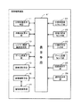
図1は、本発明の画像編集装置における一実施形態の概略構成ブロック図である。同図に示す画像編集装置は、表示手段41と、それにすべて接続された分解斜視表示手段11、注視点変更手段12、レイヤー間距離変更手段13、ズーム変更手段14、画像回転手段15、画像編集手段16、分解斜視表示指示手段21、注視点変更指示手段22、距離変更指示手段23、ズーム変更指示手段24、回転指示手段25、及び選択指示手段26と、画像編集手段16に接続された画像格納手段31と、を備えている。
Hereinafter, embodiments of the present invention will be described in detail with reference to the drawings.
FIG. 1 is a schematic block diagram of an embodiment of an image editing apparatus according to the present invention. The image editing apparatus shown in FIG. 1 includes a
表示手段41は、制御部と、固定プログラム及び固定データ等が格納されるROMと、プログラムないしデータの一時格納のためのRAMと、本発明に係る画像表示プログラムや静止画、動画像のデータ等が格納されるハードディスクと、ディスプレイ装置などで構成される汎用的なコンピュータシステムによって構成される。その表示操作は、キーボード及び/又はマウスによって実行される。 The display means 41 includes a control unit, a ROM for storing fixed programs and fixed data, a RAM for temporarily storing programs or data, an image display program according to the present invention, still image data, moving image data, etc. Is configured by a general-purpose computer system including a hard disk in which is stored and a display device. The display operation is executed by a keyboard and / or a mouse.
画像格納手段31には、それぞれが独立の画像データを含む複数のレイヤーで構成される画像が格納されている。また、その画像は、遊技機に表示されるための画像であり、2次元画像の他に、3次元画像であってもよい。画像編集手段16は、画像格納手段31に格納された画像データを初期的に読み出し、各レイヤーに係る画像が重ね合された画像として、表示手段41に表示する。
The image storage means 31 stores an image composed of a plurality of layers each including independent image data. The image is an image to be displayed on the gaming machine, and may be a three-dimensional image in addition to the two-dimensional image. The
分解斜視表示指示手段21は、表示手段41を介して、分解斜視表示手段11に、分解して斜視表示する処理を指示する。分解斜視表示指示手段21により指示された分解斜視表示手段11は、表示手段41に表示された、各レイヤーに係る画像が重ね合された画像を、前記マウスなどで注視点を位置設定した箇所において、そこで重なる各レイヤーごとを分解して斜視表示する。 The exploded perspective display instruction means 21 instructs the exploded perspective display means 11 to perform a disassembled perspective display process via the display means 41. The disassembled perspective display means 11 instructed by the exploded perspective display instruction means 21 is an image in which the images related to the respective layers displayed on the display means 41 are superimposed at a position where the point of interest is set with the mouse or the like. Then, each overlapping layer is disassembled and displayed in perspective.
注視点変更指示手段22は、前記のように最初に位置設定した注視点を表示手段41を介して別の位置にある注視点へ変更指示するもので、その指示を受けて注視点変更手段12は、注目する画像点である注視点をディスプレイ画面上の任意の位置への変更処理を指示する。注視点変更指示手段22により指示された注視点変更手段12は、分解斜視表示すべき中心点となる注視点を変更して、表示手段41に表示させる。
The gazing point change instructing means 22 instructs the gazing point initially set as described above to be changed to a gazing point in another position via the display means 41. Upon receiving the instruction, the gazing point changing means 12 Instructs the process of changing the point of interest, which is the image point of interest, to an arbitrary position on the display screen. The gazing
距離変更指示手段23は、表示手段41を介して、レイヤー間距離変更手段13に各レイヤーを接近/離反させる処理を指示する。距離変更指示手段23により指示されたレイヤー間距離変更手段13は、分解して斜視表示された各レイヤーを、注視点を中心として接近/離反させる。
The distance
ズーム変更指示手段24は、表示手段41を介して、ズーム変更手段14に画像のズーム変更処理を指示する。ズーム変更指示手段24により指示されたズーム変更手段14は、カメラ位置に相当する視点から見た画角(FOV:field of view)を変化させて、いわゆる拡大縮小率を示すズームを変化させる処理をする。
The zoom
回転指示手段25は、表示手段41を介して、画像回転手段15に画像の回転処理を指示する。回転指示手段25により指示された画像回転手段15は、分解して斜視表示された各レイヤーを、注視点を中心として回転させる。
The
選択指示手段26は、表示手段41を介して、画像編集手段16に、表示手段41に分解して斜視表示された各レイヤーのうち、編集の対象たるレイヤーを選択指示する。選択指示手段26により指示された画像編集手段16は、分解斜視表示手段11により分解して斜視表示された各レイヤーのうち、選択指示手段26により選択されたレイヤーに係る画像の編集を行う。ここでの編集は、一旦分解斜視された各レイヤーの時間変化を表示手段41のディスプレイ装置上で目視しながら、全体画像を確認しながら、所望の画像となっていないレイヤーと探し、そのレイヤーの表示画面を修正したり、また当該レイヤーの時間変化率を修正したりの様々な手法がある。
The
分解斜視表示指示手段21は、表示手段41を介して、分解斜視表示手段11に、分解斜視表示を終了する処理を指示する。分解斜視表示指示手段21により終了指示された分解斜視表示手段11は、表示手段41に表示された3次元状に表示されていた分解斜視表示を終了して、それらのレイヤーが重ね合わさった2次元の通常表示に戻す。
The exploded perspective
ここで、分解斜視表示指示手段21、注視点変更指示手段22、距離変更指示手段23、ズーム変更指示手段24、回転指示手段25、選択指示手段26の各手段は、典型的には、後述するようにマウスやタッチパネルである。また、変形例として、表示手段41を介するものではないが、後述するようにキーボードであってもよい。その他、各指示手段については、当業者であれば、各種想到できるであろう。
Here, each of the exploded perspective display instruction means 21, the gazing point change instruction means 22, the distance change instruction means 23, the zoom change instruction means 24, the rotation instruction means 25, and the selection instruction means 26 is typically described later. Like a mouse or touch panel. Further, as a modification, the
図2は、本発明の画像編集方法における一実施形態の処理手順を示すフローチャートである。図3乃至図9は、本発明の画像編集方法における一実施形態を説明するための図である。図10は、動画像のあるタイミングでの分解斜視表示を説明するための図である。以下、図1と、図3乃至図10を参照しつつ、図2に沿って、本発明の画像編集方法における一実施形態の処理手順を説明する。 FIG. 2 is a flowchart showing a processing procedure according to an embodiment of the image editing method of the present invention. 3 to 9 are diagrams for explaining an embodiment of the image editing method of the present invention. FIG. 10 is a diagram for explaining an exploded perspective display at a certain timing of a moving image. The processing procedure of an embodiment of the image editing method of the present invention will be described below with reference to FIG. 1 and FIGS. 3 to 10 and FIG.
まず、画像編集手段16は、画像格納手段31に格納された画像データにつき、静止画像、又は動画像の任意の時点での画像を表示手段41に表示させる(ステップS1)。この初期段階においては、画像は、各レイヤーが重なって通常の正面から観た(つまり正視)2次元的な状態(以下、「通常表示」と称す)で表示手段41に表示される。
First, the
次に、分解斜視表示手段11は、分解斜視表示指示手段21により、表示手段41を介して、分解斜視コマンドが入力されたか否かを判断する(ステップS2)。分解斜視表示指示手段21としては、各種考えらえる。例えば、マウスであり、それにより、ツールバー等に表示された斜視表示のためのボタンや、ドロップダウンリストに表示される文字をクリックしたりできる。また、変形例としては、キーボードであり、それに対して特定のキー入力(例えば、コントロールキーを押しながらのキーP(Perspective)の押下)を行うことで実現できる。その他これに限らず当業者であれば各種考えられるであろう。 Next, the exploded perspective display means 11 determines whether or not an exploded perspective command is input via the display means 41 by the exploded perspective display instruction means 21 (step S2). Various types of disassembled perspective display instruction means 21 can be considered. For example, a mouse can be used to click a perspective display button displayed on a toolbar or the like, or a character displayed in a drop-down list. Moreover, as a modification, it is a keyboard, and it can be realized by performing a specific key input (for example, pressing a key P (Perspective) while pressing a control key). In addition, the person skilled in the art will be able to conceive various types without being limited thereto.
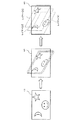
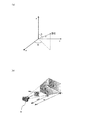
上述のように各種手段により分解斜視コマンドが入力されたと判断すると、分解斜視表示手段11は、それまで複数のレイヤーが重なって1つの画面として表示されていた全体画像を、レイヤーごとに分解して斜視的に表示手段41に表示する(ステップS3)。詳細には、図3に示すように、まず、重なったレイヤーを斜視的に表示し(同図の中央)、次に、それらのレイヤーを互いに離反させる(同図の右)。このとき、分解斜視表示手段11は、かかる遷移処理を、表示手段41上におけるマウス操作などによって、連続的に滑らかに行う。この連続的な滑らかな動作というのは、分解表示された各レイヤーを目視にて確認し、その中で時間的に変化する各レイヤー単位の画像を確認するためである。ここで、斜視的な表示は、詳細には、各レイヤーが2次元画像であるのを、統合して3次元オブジェクトに変換することであり、具体的には各2次元画像を3次元ポリゴンとそのテクスチャデータとして再構成することにより行う。なお、図3に示す例では、当該画像は、レイヤー[1]〜レイヤー[3]の3層から成っている。 When it is determined that an exploded perspective command has been input by various means as described above, the exploded perspective display means 11 decomposes the entire image that has been displayed as a single screen by overlapping a plurality of layers so far for each layer. The information is displayed on the display means 41 in a perspective manner (step S3). Specifically, as shown in FIG. 3, first, the overlapping layers are displayed in perspective (center of the figure), and then the layers are separated from each other (right of the figure). At this time, the exploded perspective display means 11 performs such a transition process continuously and smoothly by a mouse operation on the display means 41 or the like. This continuous smooth operation is for visually confirming each layer displayed in a disassembled manner, and confirming an image of each layer changing with time in the layer. Here, in detail, the perspective display is that each layer is a two-dimensional image and is integrated and converted into a three-dimensional object. Specifically, each two-dimensional image is converted into a three-dimensional polygon. This is done by reconstructing the texture data. In the example shown in FIG. 3, the image is composed of three layers, layer [1] to layer [3].
ここで、通常表示から分解斜視表示への移行は、「注視点に対する視点ベクトルの移動」と捉えることができる。「注視点」とは、視点(この視点とは、撮影を意味するとカメラが配置されている位置に相当する)から注目している画像情報の一点であり、典型的には、表示手段41の画面の中心位置を初期的には常に置くことが考えられるが、もとより初期値であるので、それには限られない。また、画像データに対しては、初期的には、各レイヤーの画像面の中心であって、積層方向でも真ん中(例えば、3枚のレイヤーであれば、2枚目のレイヤー(図3の右側の図を参照))に設定する。そこで、「注視点に対する視点ベクトルの移動」を説明するため、図4の左の図に表したように、注視点を原点とし、各レイヤーの画像面に平行な面をx−y平面とし、画像面に鉛直な方向をz軸方向とする3次元座標(以下、「画像3次元座標」と称す)を仮想的に設定する。しかして、図3に示すような通常表示から分解斜視表示への遷移は、注視点を変えずに、z軸上にある視点を、z軸から外れるようにずらすことと捉えることができる。 Here, the transition from the normal display to the exploded perspective display can be regarded as “movement of the viewpoint vector with respect to the gazing point”. The “gaze point” is a point of image information that is focused from the viewpoint (this viewpoint corresponds to the position where the camera is arranged in the sense of shooting). Although it is conceivable that the center position of the screen is always set initially, it is not limited to this because it is an initial value. For image data, it is initially the center of the image plane of each layer and is also the middle in the stacking direction (for example, if there are three layers, the second layer (the right side of FIG. 3 (Refer to the figure of))). Therefore, in order to explain “movement of the viewpoint vector with respect to the gazing point”, as shown in the left diagram of FIG. 4, the gazing point is the origin, and the plane parallel to the image plane of each layer is the xy plane, Three-dimensional coordinates (hereinafter referred to as “image three-dimensional coordinates”) having a direction perpendicular to the image plane as the z-axis direction are virtually set. Therefore, the transition from the normal display to the exploded perspective display as shown in FIG. 3 can be regarded as shifting the viewpoint on the z axis so as to deviate from the z axis without changing the gazing point.
次に、編集に係る画像が動画像データである場合には、画像が時間軸で変化しているので、編集したいタイミングを選択する(ステップS4)。但し、この編集したいタイミングの選択操作は、当該処理手順のこの段で行われる必要はなく、当該処理手順の任意の段で行うことができる。また、編集に係る画像が静止画像データの場合は、このステップは不要となる。 Next, when the image related to editing is moving image data, the image changes on the time axis, so the timing for editing is selected (step S4). However, the selection operation of the timing to be edited does not need to be performed at this stage of the processing procedure, and can be performed at an arbitrary stage of the processing procedure. Further, this step is not necessary when the image to be edited is still image data.
そこで、当該画像編集装置においては、以下のように、分解斜視表示の状態で、編集に適した様々な表示形態をとることができるようになっている。その第一が、注視点の変更による表示状態の変更である。また、第二に、各レイヤーの接近/離反または画角の変更による表示状態の変更である。更に、その第三が、注視点を中心とした、画像を含む各レイヤーの回転による表示状態の変更である。かかる3つの動作処理は、好適には、画像編集者が各レイヤーの画像を編集する際に、目視して当該注視点での各レイヤー自身の画像ないし各レイヤー相互の関係を画面上で目視して分かりやすいようにするためであり、引いては、編集し易いようにするために実行される。 Therefore, the image editing apparatus can take various display forms suitable for editing in the exploded perspective display state as described below. The first is the change of the display state by changing the point of gaze. Second, the display state is changed by approaching / separating each layer or changing the angle of view. Furthermore, the third is a change in the display state by rotating each layer including the image around the gazing point. The three operation processes are preferably performed when the image editor edits the image of each layer and visually checks the image of each layer at the point of interest or the relationship between the layers on the screen. It is executed to make it easy to edit.
まず、注視点変更手段12は、注視点変更指示手段22により、表示手段41を介して、注視点変更コマンドが入力されたか否かを判断する(ステップS5)。注視点変更指示手段22により、注視点変更コマンドが入力されたと判断すると、注視点変更手段12は、注視点の変更処理を行う(ステップS6)。
First, the gazing
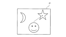
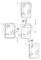
この注視点の変更は、例えば編集したい画像(特にレイヤー)を変更したい場合に行われる。そこで、例えば、図5に示すように、注視点を初期位置からレイヤー[3]内にある星の画像に移動させる場合、注視点の変更は、分解斜視表示の状態においては、図4の左の図から右の図への遷移となる。つまり、前述の画像3次元座標の原点を移動する処理と等価である。なお、図4の遷移も好適には滑らかに行われる。 This change of the gaze point is performed, for example, when it is desired to change an image (especially a layer) to be edited. Therefore, for example, as shown in FIG. 5, when the gazing point is moved from the initial position to the star image in the layer [3], the change of the gazing point is changed to the left of FIG. The transition from the figure to the right figure. That is, this is equivalent to the process of moving the origin of the image three-dimensional coordinates. Note that the transition of FIG. 4 is also preferably performed smoothly.
注視点変更指示手段22については、様々なものが考えられる。最も典型的には、マウスで任意のレイヤーをクリックすることにより、当該レイヤーを選択状態とし、その選択状態の当該レイヤー内の所望の位置(画像)を更にクリックすることが考えられる。また、上記クリック動作をタッチパネルに対するタッチ動作で行うことも考えられる。その他、当業者であれば、各種考えられるであろう。 Various gazing point change instruction means 22 are conceivable. Most typically, it is conceivable to click on an arbitrary layer with the mouse to select the layer, and further click a desired position (image) in the selected layer. It is also conceivable to perform the click operation by a touch operation on the touch panel. Others will be considered by those skilled in the art.
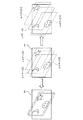
次に、レイヤー間距離変更手段13は、距離変更指示手段23により、表示手段41を介して、接近/離反コマンドが入力されたか否かを判断する(ステップS7)。距離変更指示手段23により接近/離反コマンドが入力されたと判断すると、レイヤー間距離変更手段13は、図6に示すように、分解斜視表示された画像の各レイヤーを離反させたり、接近させたりする(レイヤー間距離変更)(ステップS8)。
Next, the inter-layer
このレイヤー間距離変更の処理は、各レイヤーの画像が、表示画面41上で重ならない適当な位置に表示させる場合に行われ、例えば3次元空間における各レイヤー間の距離を変更するか、またはレイヤーの奥行きを示す方向ベクトルのスケールを変更することにより可能な処理である。具体的には、この処理は、画像3次元座標におけるz軸のスケールの変更となる。また、注視点に対して視点(カメラ)が接近/離反する動作とも捉えることができる。つまり、図7(a)に示すように、前述の画像3次元座標を球面座標とすると、原点から視点までの距離rを増減する処理である。
This inter-layer distance changing process is performed when images of the respective layers are displayed at appropriate positions on the
距離変更指示手段23については、様々なものが考えられる。例えば、マウスのホイールを操作することにより実現できる。ここで、例えば、ホイールを前方に回転させると、分解斜視表示された画像の各レイヤーが離反し、一方、ホイールを後方に回転させると、各レイヤーが接近するように構成する。また、例えば、表示手段41の片隅にプラスとマイナスのボタンを用意しておき、それらをマウスでクリックするごとに一定量、各レイヤーが離反又は接近するように構成もできる。また、タッチパネルを有している表示手段であれば、2本の指の間隔を広げるように画面を擦ると、各レイヤーが離反し、その間隔が狭まるように画面を擦ると、各レイヤーが接近するように構成することもできる。また、変形例として、例えば、キーボードの特定のキー(例えば、コントロールキーを押しながらのキーS(Separate))を押下すると押下の間、各レイヤーが離反し続け、他の特定のキー(例えば、コントロールキーを押しながらのキーA(Approach))を押下すると押下の間、各レイヤーが接近し続けるようにも構成できる。その他これに限らず当業者であれば各種考えられるであろう。 Various things can be considered as the distance change instruction means 23. For example, it can be realized by operating a mouse wheel. Here, for example, when the wheel is rotated forward, the layers of the image displayed in the exploded perspective view are separated from each other, while when the wheel is rotated backward, the layers are configured to approach each other. Further, for example, it is possible to prepare plus and minus buttons at one corner of the display means 41, and each layer is separated or approached by a certain amount each time they are clicked with the mouse. In addition, if the display means has a touch panel, if the screen is rubbed so as to widen the distance between two fingers, each layer will come apart, and if the screen is rubbed so that the gap is narrowed, each layer will approach. It can also be configured to. As a modification, for example, when a specific key on the keyboard (for example, a key S (Separate) while holding down a control key) is pressed, each layer continues to separate during the pressing, and another specific key (for example, When the key A (Approach) is pressed while pressing the control key, each layer can be configured to keep approaching while the key is pressed. In addition, the person skilled in the art will be able to conceive various types without being limited thereto.
次に、ズーム変更手段14は、ズーム変更指示手段24により、表示手段41を介して、ズーム変更コマンドが入力されたか否かを判断する(ステップS9)。ズーム変更指示手段24によりズーム変更コマンドが入力されたと判断すると、ズーム変更手段14は、図7(b)に示すように、カメラ位置に相当する視点から見た画角(FOV:field of view)を変化させて、いわゆる拡大縮小率を示すズームを変化させる処理をする(ズーム変更)(ステップS10)。
Next, the zoom change means 14 determines whether or not a zoom change command has been input via the display means 41 by the zoom change instruction means 24 (step S9). If it is determined that a zoom change command has been input by the zoom
ズーム変更指示手段24については、様々なものが考えられる。例えば、マウスのホイールを操作することにより実現できる。ここで、例えば、ホイールを前方に回転させると、いわゆるズームインし、一方、ホイールを後方に回転させると、いわゆるズームアウトするように構成する。また、例えば、表示手段41の片隅にプラスとマイナスのボタンを用意しておき、それらをマウスでクリックするごとに一定量、ズームイン又はズームアウトするように構成もできる。また、タッチパネルを有している表示手段であれば、2本の指の間隔を広げるように画面を擦ると、ズームインし、その間隔が狭まるように画面を擦ると、ズームアウトするように構成することもできる。また、変形例として、例えば、キーボードの特定のキー(例えば、コントロールキーを押しながらのキーI(Zoom-In))を押下すると押下の間、ズームインし続け、他の特定のキー(例えば、コントロールキーを押しながらのキーO(Zoom-Out))を押下すると押下の間、ズームアウトし続けるようにも構成できる。その他これに限らず当業者であれば各種考えられるであろう。 Various zoom change instruction means 24 are conceivable. For example, it can be realized by operating a mouse wheel. Here, for example, when the wheel is rotated forward, so-called zoom-in is performed, and when the wheel is rotated backward, so-called zoom-out is performed. Further, for example, a plus and minus button may be prepared in one corner of the display means 41, and a certain amount of zoom-in or zoom-out may be performed each time the mouse is clicked with the mouse. Further, if the display means has a touch panel, the screen is zoomed in when the screen is rubbed so as to widen the distance between two fingers, and the screen is zoomed out when the screen is rubbed so that the gap is narrowed. You can also. As a modification, for example, when a specific key on the keyboard (for example, key I (Zoom-In) while pressing a control key) is pressed, zooming in is continued while the other key is pressed (for example, control). When the key O (Zoom-Out)) is pressed while pressing the key, the zoom-out can be continued during the pressing. In addition, the person skilled in the art will be able to conceive various types without being limited thereto.
次に、画像回転手段15は、回転指示手段25により、表示手段41を介して、回転コマンドが入力されたか否かを判断する(ステップS11)。回転指示手段25により回転コマンドが入力されたと判断すると、画像回転手段15は、分解斜視表示された画像を注視点に対して回転させる(ステップS12)。この画像の回転処理は、視点を注視点に向けたまま注視点に対して旋回させる処理と捉えることができる。このとき、前述の注視点を原点とした画像3次元座標において、旋回の軸は、図8(a)に示すように、各x、y、z軸とすることができることは無論、任意のx軸成分、y軸成分、z軸成分により決定される任意のベクトルの方向とすることができる。この旋回軸を連続的に変化させれば、図8(b)に示すように、注視点から距離rにある視点は、半径rの球面上をくまなく移動できることとなる。
Next, the image rotation means 15 determines whether or not a rotation command has been input via the display means 41 by the rotation instruction means 25 (step S11). If it is determined that the rotation command is input by the
画像の回転、すなわち視点の旋回は、一方においては、視点の移動と、視点(カメラ)の向きの変更(カメラローテーション)の組合せ動作とも捉えることができる。つまり、カメラを平行移動させ、その後、カメラの向きを注視点に向けることと等価である。このとき、カメラの向きの変更は、図8(c)に示すように、カメラ中心(視点)を原点とした3次元空間における座標軸の任意の回転という処理で実現できる。 On the one hand, the rotation of the image, that is, the turning of the viewpoint, can be regarded as a combined operation of the movement of the viewpoint and the change of the direction of the viewpoint (camera) (camera rotation). That is, it is equivalent to moving the camera in parallel and then directing the camera to the point of interest. At this time, the change of the camera orientation can be realized by a process of arbitrary rotation of coordinate axes in a three-dimensional space with the camera center (viewpoint) as the origin, as shown in FIG.
回転指示手段25については、様々なものが考えられる。例えば、典型的には、マウスで実現できる。つまり、マウスで表示手段41を任意の方向にドラッグすると、視点が前述の球面上を移動する。例えば、マウスで表示手段41を上又は下方向にドラッグすると、球面の経線に沿って移動する。また、左又は右方向にドラッグすると、球面の緯線方向に移動する。斜めにドラッグすると、球面の斜め方向に移動する。このマウスによるドラッグ動作は、タッチパネルに対して指で擦る操作で同様に実現できる。また、表示手段41上に4方向ボタンや8方向ボタンを備えておき、それらのボタンの押下の組合せでも実現できる。更に、変形例として、キーボードの矢印キーの上下方向キーと左右方向キーの押下動作の組合せでも実現できる。
Various rotation instruction means 25 are conceivable. For example, it can typically be realized with a mouse. That is, when the display means 41 is dragged with the mouse in an arbitrary direction, the viewpoint moves on the spherical surface. For example, when the
図9は、画像の回転の例であるが、基本的な理解の便宜のため、x軸、y軸、z軸のそれぞれを単独の回転軸とした場合を示している。しかしながら、前述のように、任意の方向ベクトルを回転軸として回転可能である。 FIG. 9 shows an example of image rotation. For the sake of basic understanding, FIG. 9 shows a case where each of the x-axis, y-axis, and z-axis is a single rotation axis. However, as described above, it can be rotated with an arbitrary direction vector as a rotation axis.
ステップS4におけるタイミング選択、ステップS6における注視点変更、ステップS8におけるレイヤー間距離変更、ステップS10におけるズーム変更、ステップS12における画像回転の各処理により、編集し易い表示状態が形成されると、次に、画像編集手段16による編集処理が行われる(ステップS13)。 When an easy-to-edit display state is formed by the timing selection in step S4, the gaze point change in step S6, the inter-layer distance change in step S8, the zoom change in step S10, and the image rotation in step S12, Then, editing processing by the image editing means 16 is performed (step S13).
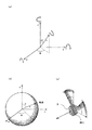
そこで、図10を参照して、具体的な動画像で説明する。図10(a)は、ルーレット数字にミサイルが命中するタイミングの動画像である。分解斜視表示前の通常表示の状態である。このように通常表示でもタイミングを選択できる。この画像を分解斜視表示すると、例えば、図10(b)に示すようになる。この具体例から明確なように、各レイヤーに含まれる各画像の重なり構成が容易に把握できることが分かる。そこで、図10(b)に示す分解斜視表示された画像に対し、選択指示手段25により所望のレイヤーを選択する。同図においては、レイヤー[2]を選択しようとしている。ここで、選択指示手段25については、様々なものが考えられる。例えば、典型的には、マウスによるポインティング操作で実現できる。または、タッチパネルに対するタッチでも同様である。図10(c)は、レイヤー[2]が選択されている状態の例である。このように、分解斜視表示の状態では、選択状態も明確に把握できる。このように選択指示手段25により所望のレイヤーが選択されると、画像編集手段15は、選択されたレイヤーに含まれる画像の編集処理を行う。なお、補足的に、図10(d)は、全てのレイヤーが選択された状態を示す図である。
Therefore, a specific moving image will be described with reference to FIG. FIG. 10A is a moving image at a timing when a missile hits a roulette number. This is a normal display state before the exploded perspective display. Thus, the timing can be selected even in normal display. When this image is displayed in an exploded perspective view, for example, it is as shown in FIG. As is clear from this specific example, it can be seen that the overlapping configuration of each image included in each layer can be easily grasped. Therefore, a desired layer is selected by the selection instruction means 25 for the image displayed in the exploded perspective view shown in FIG. In the figure, layer [2] is to be selected. Here, various selection instruction means 25 can be considered. For example, it can be typically realized by a pointing operation with a mouse. The same applies to a touch on the touch panel. FIG. 10C shows an example in which the layer [2] is selected. In this way, in the exploded perspective display state, the selection state can be clearly grasped. When a desired layer is selected by the
最後に、分解斜視表示指示手段21により分解斜視終了コマンドが入力されたか否かを判断する(ステップS14)。編集が終了して、分解斜視表示指示手段21により分解斜視終了コマンドが入力されると、分解斜視表示手段11は、画像の分解斜視表示を終了し、通常表示に戻す(ステップS15)。なお、通常表示から分解斜視表示への遷移と同様、分解斜視表示から通常表示への遷移も、表示手段41上において、連続的に滑らかに行われる。
Finally, it is determined whether or not an exploded perspective end command has been input by the exploded perspective display instruction means 21 (step S14). When the editing is finished and the exploded perspective display end command is input by the exploded perspective display instruction means 21, the exploded perspective display means 11 finishes the exploded perspective display of the image and returns to the normal display (step S15). Note that, similarly to the transition from the normal display to the exploded perspective display, the transition from the exploded perspective display to the normal display is continuously and smoothly performed on the
分解斜視表示指示手段21による分解斜視終了コマンドを与える方法についても、分解斜視コマンドと同様である。つまり、マウスにより、ツールバーに表示された斜視表示終了のためのボタンや、ドロップダウンリストに表示される文字をクリックしたりできる。また、変形例として、キーボードに対して特定のキー入力(例えば、コントロールキーを押しながらのキーQ(Quit)の押下)を行ったりすることで実現できる。その他これに限らず当業者であれば各種考えられるであろう。 The method of giving the exploded perspective end command by the exploded perspective display instruction means 21 is the same as the exploded perspective command. In other words, the mouse can be used to click a button for ending the perspective display displayed on the toolbar or a character displayed in the drop-down list. Further, as a modification, it can be realized by performing a specific key input (for example, pressing a key Q (Quit) while pressing a control key) on the keyboard. In addition, the person skilled in the art will be able to conceive various types without being limited thereto.
以上のように、本発明の画像編集方法及び画像編集装置の一実施形態によれば、各レイヤー[1]〜[3]に含まれる画像を分解斜視表示し、また、その分解斜視表示の状態で、画像を回転させたり、レイヤー間を拡縮させたり、ズームイン/アウトしたり、注視点を変更したりすることにより、各レイヤーにおける各画像の重なり具合や大きさを視覚的に認識できると共に、任意の画像を編集し易いような位置関係で各画像を表示できる。従って、編集作業を短時間で容易に行える。 As described above, according to the embodiment of the image editing method and the image editing apparatus of the present invention, the images included in the layers [1] to [3] are displayed in exploded perspective view, and the exploded perspective display state is displayed. By rotating the image, scaling between layers, zooming in / out, changing the point of sight, you can visually recognize the overlap and size of each image in each layer, Each image can be displayed in a positional relationship that makes it easy to edit an arbitrary image. Therefore, the editing work can be easily performed in a short time.
なお、上述の実施形態においては、注視点変更コマンドの入力の判断、接近/離反コマンドの入力の判断、ズーム変更コマンドの入力の判断、回転コマンドの入力の判断は、その順で行っているが、当業者であれば、例えば画像編集の進行に応じて、それらは通常は順不同であり、各指示手段を介して編集者から任意の時点及び回数で与えられるコマンドによるものであることが理解できるであろう。 In the above-described embodiment, the determination of the gaze point change command, the determination of the approach / separation command input, the determination of the input of the zoom change command, and the determination of the input of the rotation command are performed in that order. Those skilled in the art can understand that, for example, according to the progress of image editing, they are usually out of order, and are based on commands given from the editor at an arbitrary time and number through each instruction means. Will.
また、上述の実施形態においては、とりわけ図面表示の便宜のため、レイヤーを3層としたが、これに限られることなく、より多くのレイヤー数でも可能である。特にその数が比較的大きいときに効果を大きい。 Further, in the above-described embodiment, the number of layers is three for the convenience of drawing display. However, the number of layers is not limited to this, and a larger number of layers is possible. The effect is particularly great when the number is relatively large.
本発明の画像編集方法及び画像編集装置は、例えばパチンコ機やゲーム機のような遊技機で表示される画像の編集に利用できる。
The image editing method and the image editing apparatus of the present invention can be used for editing an image displayed on a gaming machine such as a pachinko machine or a game machine.
11 分割斜視表示手段
12 注視点変更手段
13 レイヤー間距離変更手段
14 ズーム変更手段
15 画像回転手段
16 画像編集手段
21 分解斜視表示指示手段
22 注視点変更指示手段
23 距離変更指示手段
24 ズーム変更指示手段
25 回転指示手段
26 選択指示手段
31 画像格納手段
41 表示手段
11 Divided perspective display means 12 Gaze
Claims (10)
a)前記ディスプレイ装置に表示された動画像に対して分解斜視表示指示手段を介して入力された指示に応じて、分解斜視表示手段により各レイヤーを分解斜視表示するステップと、
b)前記ディスプレイ装置に分解斜視表示された動画像を時間的に推移させるステップと、
c)前記ディスプレイ装置に分解斜視表示された動画像について、回転指示手段、距離変更指示手段、及びズーム変更指示手段を介して入力された各指示に応じて、注視点変更手段により任意に設定できる注目する画像点たる注視点を中心として画像回転手段により回転させる操作、レイヤー間距離変更手段により前記注視点を中心として各レイヤーを接近/離反させる操作、及びズーム変更手段により前記注視点を中心としてズームイン/アウトさせる操作のうちの少なくとも1つを行うことにより、各レイヤーの相互の関係を容易に把握できるようにするステップと、
d)前記ステップb)及び前記ステップc)を任意に繰り返して不本意な動画像の表出の要因となっているレイヤーを探索し、選択指示手段を介して選択するステップと、
e)前記選択されたレイヤーに係る画像を、前記制御部上で機能する画像編集手段により編集するステップと、
を備えることを特徴とする画像編集方法。 Storage means for storing a moving image composed of a plurality of layers each including independent moving image data, a control unit for processing information on the moving image, and a display device for displaying the moving image An image editing method in an image editing apparatus comprising:
a) disassembling and displaying each layer by the exploded perspective display means in response to an instruction inputted via the exploded perspective display instruction means for the moving image displayed on the display device;
b) temporally transitioning the moving image displayed in exploded perspective on the display device;
c) The moving image displayed in an exploded perspective view on the display device can be arbitrarily set by the gaze point changing unit according to each instruction input via the rotation instruction unit, the distance change instruction unit, and the zoom change instruction unit. An operation for rotating the image by the image rotation means around the point of interest as the image point of interest, an operation for moving each layer closer to or away from the point of interest by the distance changing means between layers, and a point of focus on the point of interest by the zoom change means Performing at least one of the operations to zoom in / out so that the mutual relationship between the layers can be easily grasped;
d) Steps b) and c) are arbitrarily repeated to search for a layer that is a cause of unintentional moving image expression, and selected via a selection instruction unit;
e) editing an image related to the selected layer by image editing means functioning on the control unit;
An image editing method comprising:
前記ディスプレイ装置に表示された動画像に対して分解斜視表示を指示するための分解斜視表示指示手段と、
前記分解斜視表示指示手段により入力された指示に応じて、各レイヤーを分解斜視表示すための分解斜視表示手段と、
前記ディスプレイ装置に分解斜視表示された動画像に対して、注目する画像点たる注視点の位置の変更を指示するための注視点変更指示手段と、
前記注視点変更指示手段により入力された指示に応じて、前記注視点を変更する注視点変更手段と、
前記ディスプレイ装置に分解斜視表示された動画像に対して回転指示を行うための回転指示手段と、
前記回転指示手段により入力された指示に応じて、前記注視点を中心として回転させる画像回転手段と、
前記ディスプレイ装置に分解斜視表示された動画像に対して距離変更指示を行うための距離変更指示手段と、
前記距離変更指示手段により入力された指示に応じて、前記注視点を中心として各レイヤーを接近/離反させるレイヤー間距離変更手段と、
前記ディスプレイ装置に分解斜視表示された動画像に対してズームイン/アウトの指示を行うためのズーム変更指示手段と、
前記ズーム変更指示手段により入力された指示に応じて、前記注視点を中心としてズームイン/アウトさせるズーム変更手段と、
前記ディスプレイ装置に分解斜視表示された動画像を時間的に推移させる手段と、
前記時間的推移手段による操作と、前記注視点変更手段、前記画像回転手段、前記レイヤー間距離変更手段、及び前記ズーム変更手段のうちの少なくとも1つの操作を行って各レイヤーの相互の関係を容易に把握できるようになった状態で、不本意な動画像の表出の要因となっているレイヤーを探索して選択するための選択指示手段と、
前記選択指示手段により選択されたレイヤーに係る画像を編集するための、前記制御部上で機能する画像編集手段と、
を備えることを特徴とする画像編集装置。 Storage means for storing a moving image composed of a plurality of layers each including independent moving image data, a control unit for processing information on the moving image, and a display device for displaying the moving image An image editing apparatus comprising:
An exploded perspective display instruction means for instructing an exploded perspective display for a moving image displayed on the display device;
In accordance with an instruction input by the exploded perspective display instruction means, an exploded perspective display means for displaying an exploded perspective view of each layer;
Gazing point change instructing means for instructing to change the position of the gazing point, which is an image point of interest, with respect to the moving image displayed in an exploded perspective view on the display device;
Gaze point changing means for changing the gaze point in accordance with an instruction input by the gaze point changing instruction unit;
Rotation instruction means for giving a rotation instruction to the moving image displayed in an exploded perspective view on the display device;
Image rotating means for rotating around the gazing point in accordance with an instruction input by the rotation instructing means;
A distance change instruction means for giving a distance change instruction to the moving image displayed in an exploded perspective view on the display device;
In accordance with an instruction input by the distance change instruction means, an inter-layer distance change means for approaching / separating each layer around the gazing point;
Zoom change instruction means for instructing zoom-in / out on a moving image displayed in an exploded perspective view on the display device;
Zoom changing means for zooming in / out around the gazing point in accordance with an instruction input by the zoom change instructing means;
Means for temporally shifting a moving image displayed in an exploded perspective view on the display device;
The mutual relationship between the layers is facilitated by performing at least one of the operation by the temporal transition means and the gaze point changing means, the image rotating means, the inter-layer distance changing means, and the zoom changing means. Selection instruction means for searching for and selecting a layer that is a cause of unintentional moving image display,
Image editing means that functions on the control unit for editing an image related to the layer selected by the selection instruction means ;
Image editing apparatus comprising: a.
Priority Applications (1)
| Application Number | Priority Date | Filing Date | Title |
|---|---|---|---|
| JP2011129648A JP5211368B2 (en) | 2011-06-09 | 2011-06-09 | Image editing method and image editing apparatus |
Applications Claiming Priority (1)
| Application Number | Priority Date | Filing Date | Title |
|---|---|---|---|
| JP2011129648A JP5211368B2 (en) | 2011-06-09 | 2011-06-09 | Image editing method and image editing apparatus |
Publications (2)
| Publication Number | Publication Date |
|---|---|
| JP2012256254A JP2012256254A (en) | 2012-12-27 |
| JP5211368B2 true JP5211368B2 (en) | 2013-06-12 |
Family
ID=47527752
Family Applications (1)
| Application Number | Title | Priority Date | Filing Date |
|---|---|---|---|
| JP2011129648A Expired - Fee Related JP5211368B2 (en) | 2011-06-09 | 2011-06-09 | Image editing method and image editing apparatus |
Country Status (1)
| Country | Link |
|---|---|
| JP (1) | JP5211368B2 (en) |
Families Citing this family (6)
| Publication number | Priority date | Publication date | Assignee | Title |
|---|---|---|---|---|
| JP6136409B2 (en) * | 2013-03-15 | 2017-05-31 | 株式会社リコー | Display device |
| CN106204448B (en) * | 2016-07-04 | 2019-09-13 | 北京空间飞行器总体设计部 | Stepless scaling and display method and display system for hierarchical power supply and distribution map of spacecraft |
| JP6532094B1 (en) | 2018-04-06 | 2019-06-19 | 株式会社アクセル | Display processing apparatus, display processing method, and program |
| US12015732B2 (en) | 2019-05-31 | 2024-06-18 | Apple Inc. | Device, method, and graphical user interface for updating a background for home and wake screen user interfaces |
| US11989398B2 (en) * | 2021-10-22 | 2024-05-21 | Ebay Inc. | Digital content view control system |
| US12566540B2 (en) | 2022-05-10 | 2026-03-03 | Apple Inc. | Devices, methods, and graphical user interfaces for providing notifications and application information |
Family Cites Families (4)
| Publication number | Priority date | Publication date | Assignee | Title |
|---|---|---|---|---|
| JP3262910B2 (en) * | 1993-08-04 | 2002-03-04 | キヤノン株式会社 | Image processing method and apparatus |
| JP3182321B2 (en) * | 1994-12-21 | 2001-07-03 | 三洋電機株式会社 | Generation method of pseudo stereoscopic video |
| JP4296521B2 (en) * | 2007-02-13 | 2009-07-15 | ソニー株式会社 | Display control apparatus, display control method, and program |
| JP2011002968A (en) * | 2009-06-17 | 2011-01-06 | Sega Corp | Program, recording medium, and display controller |
-
2011
- 2011-06-09 JP JP2011129648A patent/JP5211368B2/en not_active Expired - Fee Related
Also Published As
| Publication number | Publication date |
|---|---|
| JP2012256254A (en) | 2012-12-27 |
Similar Documents
| Publication | Publication Date | Title |
|---|---|---|
| JP5211368B2 (en) | Image editing method and image editing apparatus | |
| US20160328887A1 (en) | Systems and methods for providing assistance for manipulating objects using virtual proxies and virtual replicas | |
| US10642345B2 (en) | Avionics maintenance training | |
| CN103213125B (en) | There is robot teaching's device that 3D shows | |
| US10671239B2 (en) | Three dimensional digital content editing in virtual reality | |
| US20220326967A1 (en) | Devices, methods, systems, and media for an extended screen distributed user interface in augmented reality | |
| JP4258850B2 (en) | Image processing apparatus and method | |
| KR100856219B1 (en) | Computer-readable medium that stores animation generator | |
| US8839136B2 (en) | Method of controlling virtual object or view point on two dimensional interactive display | |
| EP2395413B1 (en) | Gesture-based human machine interface | |
| EP3217258B1 (en) | Method and system for editing scene in three-dimensional space | |
| US20160196692A1 (en) | Virtual lasers for interacting with augmented reality environments | |
| US20070146352A1 (en) | Portable device having rotatable input buttons and method of operating the same | |
| CN119383447A (en) | Image processing device, image processing method, system, computer program product, storage medium and computer-implemented method | |
| KR20190059727A (en) | Interactive system for controlling complexed object of virtual reality environment | |
| US11010014B2 (en) | Techniques for transitioning from a first navigation scheme to a second navigation scheme | |
| JP5370869B2 (en) | Editing-oriented moving image display method and program thereof | |
| CN109416596B (en) | Computing device and method for scroll steering and tap steering for virtual reality environments | |
| WO2012026322A1 (en) | Method and device for editing layout of objects | |
| JP2013012036A (en) | Image reproduction control device, image reproduction control method and image reproduction control program | |
| Jeon et al. | Portallite: A Bare-Hand 3D Portal Creation and Manipulation Technique for Remote Object Interactions in Virtual Reality | |
| EP3599538B1 (en) | Method and apparatus for adding interactive objects to a virtual reality environment | |
| US20160334971A1 (en) | Object Manipulation System and Method | |
| JP6344662B2 (en) | Image processing apparatus and method | |
| JP6075720B2 (en) | Image processing apparatus and method |
Legal Events
| Date | Code | Title | Description |
|---|---|---|---|
| A521 | Request for written amendment filed |
Free format text: JAPANESE INTERMEDIATE CODE: A523 Effective date: 20121126 |
|
| TRDD | Decision of grant or rejection written | ||
| A01 | Written decision to grant a patent or to grant a registration (utility model) |
Free format text: JAPANESE INTERMEDIATE CODE: A01 Effective date: 20130108 |
|
| A61 | First payment of annual fees (during grant procedure) |
Free format text: JAPANESE INTERMEDIATE CODE: A61 Effective date: 20130205 |
|
| R150 | Certificate of patent or registration of utility model |
Ref document number: 5211368 Country of ref document: JP Free format text: JAPANESE INTERMEDIATE CODE: R150 |
|
| FPAY | Renewal fee payment (event date is renewal date of database) |
Free format text: PAYMENT UNTIL: 20160308 Year of fee payment: 3 |
|
| R250 | Receipt of annual fees |
Free format text: JAPANESE INTERMEDIATE CODE: R250 |
|
| R250 | Receipt of annual fees |
Free format text: JAPANESE INTERMEDIATE CODE: R250 |
|
| R250 | Receipt of annual fees |
Free format text: JAPANESE INTERMEDIATE CODE: R250 |
|
| R250 | Receipt of annual fees |
Free format text: JAPANESE INTERMEDIATE CODE: R250 |
|
| R250 | Receipt of annual fees |
Free format text: JAPANESE INTERMEDIATE CODE: R250 |
|
| R250 | Receipt of annual fees |
Free format text: JAPANESE INTERMEDIATE CODE: R250 |
|
| R250 | Receipt of annual fees |
Free format text: JAPANESE INTERMEDIATE CODE: R250 |
|
| LAPS | Cancellation because of no payment of annual fees |