JP5207663B2 - Exposure system and device manufacturing method - Google Patents
Exposure system and device manufacturing method Download PDFInfo
- Publication number
- JP5207663B2 JP5207663B2 JP2007146347A JP2007146347A JP5207663B2 JP 5207663 B2 JP5207663 B2 JP 5207663B2 JP 2007146347 A JP2007146347 A JP 2007146347A JP 2007146347 A JP2007146347 A JP 2007146347A JP 5207663 B2 JP5207663 B2 JP 5207663B2
- Authority
- JP
- Japan
- Prior art keywords
- temperature
- fluid
- exposure apparatus
- adjusting means
- unit
- Prior art date
- Legal status (The legal status is an assumption and is not a legal conclusion. Google has not performed a legal analysis and makes no representation as to the accuracy of the status listed.)
- Active
Links
Images


Classifications
-
- H—ELECTRICITY
- H01—ELECTRIC ELEMENTS
- H01L—SEMICONDUCTOR DEVICES NOT COVERED BY CLASS H10
- H01L21/00—Processes or apparatus adapted for the manufacture or treatment of semiconductor or solid state devices or of parts thereof
- H01L21/02—Manufacture or treatment of semiconductor devices or of parts thereof
- H01L21/027—Making masks on semiconductor bodies for further photolithographic processing not provided for in group H01L21/18 or H01L21/34
- H01L21/0271—Making masks on semiconductor bodies for further photolithographic processing not provided for in group H01L21/18 or H01L21/34 comprising organic layers
- H01L21/0273—Making masks on semiconductor bodies for further photolithographic processing not provided for in group H01L21/18 or H01L21/34 comprising organic layers characterised by the treatment of photoresist layers
- H01L21/0274—Photolithographic processes
-
- G—PHYSICS
- G03—PHOTOGRAPHY; CINEMATOGRAPHY; ANALOGOUS TECHNIQUES USING WAVES OTHER THAN OPTICAL WAVES; ELECTROGRAPHY; HOLOGRAPHY
- G03F—PHOTOMECHANICAL PRODUCTION OF TEXTURED OR PATTERNED SURFACES, e.g. FOR PRINTING, FOR PROCESSING OF SEMICONDUCTOR DEVICES; MATERIALS THEREFOR; ORIGINALS THEREFOR; APPARATUS SPECIALLY ADAPTED THEREFOR
- G03F7/00—Photomechanical, e.g. photolithographic, production of textured or patterned surfaces, e.g. printing surfaces; Materials therefor, e.g. comprising photoresists; Apparatus specially adapted therefor
- G03F7/70—Microphotolithographic exposure; Apparatus therefor
- G03F7/708—Construction of apparatus, e.g. environment aspects, hygiene aspects or materials
- G03F7/70858—Environment aspects, e.g. pressure of beam-path gas, temperature
-
- G—PHYSICS
- G03—PHOTOGRAPHY; CINEMATOGRAPHY; ANALOGOUS TECHNIQUES USING WAVES OTHER THAN OPTICAL WAVES; ELECTROGRAPHY; HOLOGRAPHY
- G03F—PHOTOMECHANICAL PRODUCTION OF TEXTURED OR PATTERNED SURFACES, e.g. FOR PRINTING, FOR PROCESSING OF SEMICONDUCTOR DEVICES; MATERIALS THEREFOR; ORIGINALS THEREFOR; APPARATUS SPECIALLY ADAPTED THEREFOR
- G03F7/00—Photomechanical, e.g. photolithographic, production of textured or patterned surfaces, e.g. printing surfaces; Materials therefor, e.g. comprising photoresists; Apparatus specially adapted therefor
- G03F7/70—Microphotolithographic exposure; Apparatus therefor
- G03F7/708—Construction of apparatus, e.g. environment aspects, hygiene aspects or materials
- G03F7/7085—Detection arrangement, e.g. detectors of apparatus alignment possibly mounted on wafers, exposure dose, photo-cleaning flux, stray light, thermal load
-
- G—PHYSICS
- G03—PHOTOGRAPHY; CINEMATOGRAPHY; ANALOGOUS TECHNIQUES USING WAVES OTHER THAN OPTICAL WAVES; ELECTROGRAPHY; HOLOGRAPHY
- G03F—PHOTOMECHANICAL PRODUCTION OF TEXTURED OR PATTERNED SURFACES, e.g. FOR PRINTING, FOR PROCESSING OF SEMICONDUCTOR DEVICES; MATERIALS THEREFOR; ORIGINALS THEREFOR; APPARATUS SPECIALLY ADAPTED THEREFOR
- G03F7/00—Photomechanical, e.g. photolithographic, production of textured or patterned surfaces, e.g. printing surfaces; Materials therefor, e.g. comprising photoresists; Apparatus specially adapted therefor
- G03F7/70—Microphotolithographic exposure; Apparatus therefor
- G03F7/708—Construction of apparatus, e.g. environment aspects, hygiene aspects or materials
- G03F7/70991—Connection with other apparatus, e.g. multiple exposure stations, particular arrangement of exposure apparatus and pre-exposure and/or post-exposure apparatus; Shared apparatus, e.g. having shared radiation source, shared mask or workpiece stage, shared base-plate; Utilities, e.g. cable, pipe or wireless arrangements for data, power, fluids or vacuum
Description
本発明は、基板を露光する露光装置と該露光装置に流路を介して流体を供給する流体供給装置とを有する露光システム、およびデバイス製造方法に関するものである。 The present invention relates to an exposure system having an exposure apparatus that exposes a substrate and a fluid supply apparatus that supplies a fluid to the exposure apparatus via a flow path, and a device manufacturing method.
近年、ICやLSI等の半導体集積回路は、高い生産性が要求され、これに伴い半導体露光装置の消費電力は増加する傾向にある。
その一方で、回路パターンは益々、微細化され、露光装置内の環境をより安定に維持する必要性が生じている。
露光装置内で発生する熱を回収し、また、露光装置が設置されているクリーンルームの温度変化等の影響を抑制するために高精度に温度制御された流体である空気あるいは液体の冷媒が露光装置に供給される。
クリーンルーム内の空気には微量のアンモニア、アミン等の塩基性ガス、硫酸、硝酸、塩化水素等の酸性ガス、およびシロキサン等の有機ガスの化学汚染物質が含まれる。
しかし、これらの化学汚染物質を含んだ空気を露光装置に取り入れると、露光光源である短波長紫外線のエキシマレーザ光等により光化学反応を起こし、露光装置内の光学部品の表面に曇り物質として付着する。
この曇り物質の付着により露光光の照度低下や照度むらが発生し、所定の露光性能を維持できなくなる場合がある。
In recent years, semiconductor integrated circuits such as ICs and LSIs are required to have high productivity, and accordingly, the power consumption of semiconductor exposure apparatuses tends to increase.
On the other hand, circuit patterns are increasingly miniaturized, and there is a need to maintain the environment in the exposure apparatus more stably.
Air or liquid refrigerant, which is a fluid whose temperature is controlled with high accuracy in order to recover the heat generated in the exposure apparatus and to suppress the influence of temperature change or the like of the clean room in which the exposure apparatus is installed, is the exposure apparatus. To be supplied.
The air in the clean room contains trace amounts of basic gases such as ammonia and amines, acidic gases such as sulfuric acid, nitric acid and hydrogen chloride, and organic gas chemical pollutants such as siloxane.
However, when air containing these chemical contaminants is incorporated into the exposure apparatus, a photochemical reaction is caused by the short-wavelength ultraviolet excimer laser light, which is the exposure light source, and adheres to the surface of the optical components in the exposure apparatus as a cloudy substance. .
The adhesion of the cloudy substance may cause a decrease in illuminance or uneven illuminance of the exposure light, making it impossible to maintain a predetermined exposure performance.
また、これらの空気中に含まれる化学汚染物質はppb以下の濃度に低減することが要求されるため、ケミカルフィルタが装着される。
ケミカルフィルタは、塩基性ガスや酸性ガスをイオン交換反応により除去し、有機ガスを活性炭により物理吸着して除去するものである。
このケミカルフィルタの形状は様々なものがあるが、例えば、各辺が600mmの四辺形、厚さ60mmのものを、設置環境と必要とされる低減濃度に合わせて数段重ねて使用される。
ケミカルフィルタを透過した空気は、化学汚染物質濃度は低減されるが、ケミカルフィルタ自体の熱容量が非常に大きいため、熱時定数が数分〜数十分と大きくなり、ケミカルフィルタの入口の温度と出口の温度は大きな時間遅れを有することとなる。
また、ケミカルフィルタは、化学汚染物質の除去には効果があるが、ケミカルフィルタ前後の空気の湿度が変化すると、空気中の水分の吸収または蒸発を行う特性がある。
このため、その際の吸着熱または蒸発熱によりケミカルフィルタの下流では空気の温度変動が発生する。
このケミカルフィルタの湿度による温度変動の影響を低減する従来技術として特開2002−158170号公報(特許文献1)が提案されている。
また、露光装置と流体供給装置を分離した従来技術として特開平11−135429号公報(特許文献2)が提案されている。
The chemical filter removes basic gas and acid gas by ion exchange reaction and physically removes organic gas by activated carbon.
There are various types of chemical filters. For example, a quadrilateral with a side of 600 mm and a thickness of 60 mm are used in several stages according to the installation environment and the required reduced concentration.
The air that has passed through the chemical filter has a reduced chemical pollutant concentration, but since the heat capacity of the chemical filter itself is very large, the thermal time constant increases from several minutes to several tens of minutes, and the temperature at the inlet of the chemical filter The outlet temperature will have a large time delay.
The chemical filter is effective in removing chemical contaminants, but has a characteristic of absorbing or evaporating moisture in the air when the humidity of the air before and after the chemical filter changes.
For this reason, temperature fluctuations of the air occur downstream of the chemical filter due to heat of adsorption or heat of evaporation at that time.
Japanese Laid-Open Patent Publication No. 2002-158170 (Patent Document 1) has been proposed as a conventional technique for reducing the influence of temperature fluctuation due to the humidity of the chemical filter.
Japanese Patent Laid-Open No. 11-135429 (Patent Document 2) has been proposed as a conventional technique in which an exposure apparatus and a fluid supply apparatus are separated.
しかし、特開2002−158170号公報(特許文献1)の従来技術では、ケミカルフィルタの下流に温度センサを配置しケミカルフィルタの前段に置かれた加熱器を制御する。
このため、先に述べたケミカルフィルタの大きな熱時定数により温度制御系の応答性が著しく制限される。
さらに、ケミカルフィルタで発生する温度外乱やケミカルフィルタの下流で重畳する環境変化や露光装置内の負荷変動等による外乱を十分低減できないという問題点があった。
また、この従来技術では、ケミカルフィルタの下流の温度センサにより加熱器を制御し、加熱器の前段に配置された冷却器と冷却器の温度を測定するために取り付けられた温度センサにより冷却器を制御する。
2つの温度制御は独立して制御されるため、先に述べたケミカルフィルタで発生する温度外乱やケミカルフィルタの下流で重畳する温度外乱が加熱器の加熱能力を超える大きな外乱となった場合には、高精度な温度制御を行うことができない。
この結果として露光装置に供給する流体の温度安定性を要求値に維持することができないという問題点があった。
また、ケミカルフィルタは、形状が非常に大きいため露光装置のフットプリントが増加し、結果として露光装置の設置に必要なクリーンルームのスペースが増加するという問題点があった。
However, in the prior art disclosed in Japanese Patent Application Laid-Open No. 2002-158170 (Patent Document 1), a temperature sensor is arranged downstream of the chemical filter to control a heater placed in front of the chemical filter.
For this reason, the responsiveness of the temperature control system is significantly limited by the large thermal time constant of the chemical filter described above.
Furthermore, there has been a problem that disturbance due to temperature disturbance generated in the chemical filter, environmental change superimposed downstream of the chemical filter, load fluctuation in the exposure apparatus, or the like cannot be sufficiently reduced.
Further, in this prior art, the heater is controlled by a temperature sensor downstream of the chemical filter, and the cooler is arranged by a temperature sensor disposed in front of the heater and a temperature sensor attached to measure the temperature of the cooler. Control.
Since the two temperature controls are controlled independently, if the temperature disturbance generated in the chemical filter described above or the temperature disturbance superimposed downstream of the chemical filter becomes a large disturbance exceeding the heating capacity of the heater, High-precision temperature control cannot be performed.
As a result, there is a problem that the temperature stability of the fluid supplied to the exposure apparatus cannot be maintained at the required value.
In addition, since the chemical filter has a very large shape, the footprint of the exposure apparatus increases, resulting in an increase in the clean room space necessary for installing the exposure apparatus.
次に、上記の特開平11−135429号公報(特許文献2)の従来技術では、露光装置内に温度調整手段と温度調整手段の下流に温度センサを配置し、温度制御部により温度制御を行う。
更に、前記温度センサの値を、別置きの流体供給装置にフィードバックして流体供給装置内に配置された加熱器を操作して露光装置に供給する流体の温度を制御するよう構成されている。
しかし、1つの温度センサに対し2つの温度調整手段を設けているため、両者で制御の干渉が発生し、高精度な温度制御を行うことが困難であるという問題点があった。
そこで、本発明は、露光装置内の温度安定性を改善することを例示的目的とする。
Next, in the prior art disclosed in Japanese Patent Laid-Open No. 11-135429 (Patent Document 2), a temperature adjustment unit and a temperature sensor are disposed downstream of the temperature adjustment unit in the exposure apparatus, and temperature control is performed by a temperature control unit. .
Further, the value of the temperature sensor is fed back to a separate fluid supply device, and the temperature of the fluid supplied to the exposure apparatus is controlled by operating a heater disposed in the fluid supply device.
However, since two temperature adjusting means are provided for one temperature sensor, there is a problem that control interference occurs between them and it is difficult to perform highly accurate temperature control.
Accordingly, an object of the present invention is to improve the temperature stability in the exposure apparatus.
上記課題を解決するための本発明の露光装置システムは、基板を露光する露光装置と、前記露光装置に流路を介して流体を供給する流体供給装置と、を有する露光システムであって、前記流体供給装置は、前記露光装置を介して前記流体を流すための送流手段と、前記流体の温度を調整する第1の温度調整手段と、前記流体供給装置内において前記第1の温度調整手段の下流に配され、前記流体中の不要物を除去する除去手段と、前記第1の温度調整手段と前記除去手段との間に配され、前記流体の温度を計測し、該計測された温度の情報を前記第1の温度調整手段の制御に供する第1の温度計測手段と、前記流体供給装置内において前記除去手段の下流に配され、前記流体の温度を調整する第2の温度調整手段と、を有し、前記露光装置は、前記第2の温度調整手段の下流に配されて前記流体供給装置から供給される前記流体の温度を計測する第2の温度計測手段、を有し、前記露光システムは、前記第1の温度計測手段により計測された温度の情報に基づいて前記第1の温度調整手段の動作を制御する第1の制御演算部と、前記第2の温度計測手段により計測された温度の情報に基づいて前記第2の温度調整手段の動作を制御する第2の制御演算部と、前記第2の制御演算部から前記第2の温度調整手段に対して出力される操作量と目標操作量との偏差に応じた出力を行う第3の制御演算部と、を有し、前記第1の制御演算部は、前記第1の温度計測手段により計測された温度の情報と、前記第3の制御演算部の出力とに基づき、前記第1の温度調整手段の動作を制御する、ことを特徴とする。 An exposure apparatus system of the present invention for solving the above problem is an exposure system comprising an exposure apparatus that exposes a substrate and a fluid supply device that supplies a fluid to the exposure apparatus via a flow path, The fluid supply apparatus includes a flow sending means for flowing the fluid through the exposure apparatus, a first temperature adjusting means for adjusting the temperature of the fluid, and the first temperature adjusting means in the fluid supply apparatus. Is disposed between the removal means for removing unnecessary substances in the fluid, the first temperature adjustment means and the removal means, and measures the temperature of the fluid, and the measured temperature And a second temperature adjusting means for adjusting the temperature of the fluid, the first temperature measuring means for controlling the first temperature adjusting means, and the downstream of the removing means in the fluid supply device. And the exposure apparatus A second temperature measuring unit that is disposed downstream of the second temperature adjusting unit and that measures the temperature of the fluid supplied from the fluid supply device; and the exposure system includes the first temperature measuring unit. A first control calculation unit for controlling the operation of the first temperature adjusting unit based on the temperature information measured by the unit, and the first control calculating unit based on the temperature information measured by the second temperature measuring unit. A second control calculation unit that controls the operation of the second temperature adjustment unit, and a deviation between the operation amount output from the second control calculation unit to the second temperature adjustment unit and the target operation amount. A third control calculation unit that performs output, and the first control calculation unit outputs information on the temperature measured by the first temperature measurement unit and the output of the third control calculation unit. To control the operation of the first temperature adjusting means. The features.
さらに、本発明の露光装置システムは、基板を露光する露光装置と、前記露光装置に流路を介して液体を供給する液体供給装置と、を有する露光システムであって、前記液体供給装置は、前記露光装置を介して前記液体を流すための送流手段と、前記液体の温度を調整する第1の温度調整手段と、前記液体供給装置内において前記第1の温度調整手段の下流に配され、前記液体の温度を計測し、該計測された温度の情報を前記第1の温度調整手段の制御に供する第1の温度計測手段と、前記液体供給装置内において前記第1の温度調整手段の下流に配されるタンクと、を有し、前記露光装置は、前記第1の温度調整手段の下流に配されて前記液体供給装置から供給される前記液体の温度を計測する第2の温度計測手段と、前記露光装置内において前記第2の温度計測手段の下流に配され、前記液体の温度を調整する第2の温度調整手段と、
前記露光装置内において前記第2の温度調整手段の下流に配され、前記液体の温度を計測し、該計測された温度の情報を前記第2の温度調整手段の制御に供する第3の温度計測手段と、を有し、前記第1の温度調整手段は、前記第1の温度計測手段により計測された温度の情報と前記第2の温度計測手段により計測された温度の情報とに基づき、前記液体の温度を調整し、前記第2の温度調整手段は、前記第3の温度計測手段により計測された温度の情報に基づき、前記液体の温度を調整する、ことを特徴とする。
Further, the exposure apparatus system of the present invention, an exposure apparatus for exposing a substrate, an exposure system having a liquid supply device supplying the liquid through the passage to the exposure device, the liquid supply device, A flow sending means for flowing the liquid through the exposure apparatus, a first temperature adjusting means for adjusting the temperature of the liquid , and a downstream of the first temperature adjusting means in the liquid supply apparatus. , the temperature of the liquid is measured, the first temperature measuring means provided for control of the measured temperature information to said first temperature adjusting means, said first temperature adjusting means in said liquid supply device includes a tank that is disposed downstream, the said exposure device, a second temperature measurement for measuring temperature of the liquid supplied from the liquid supply device is arranged downstream of the first temperature adjusting means Means in the exposure apparatus Disposed downstream of the second temperature measuring means Te, a second temperature adjusting means for adjusting the temperature of the liquid,
A third temperature measurement that is arranged downstream of the second temperature adjusting means in the exposure apparatus, measures the temperature of the liquid , and uses the measured temperature information to control the second temperature adjusting means. And the first temperature adjusting means is based on the temperature information measured by the first temperature measuring means and the temperature information measured by the second temperature measuring means. The temperature of the liquid is adjusted, and the second temperature adjusting means adjusts the temperature of the liquid based on the temperature information measured by the third temperature measuring means.
さらに、本発明の露光装置システムは、基板を露光する露光装置と、前記露光装置に流路を介して流体を供給する流体供給装置と、を有する露光システムであって、前記流体供給装置は、前記露光装置を介して前記流体を流すための送流手段と、前記流体の温度を調整する第1の温度調整手段と、前記流体供給装置内において前記第1の温度調整手段の下流に配され、前記流体の温度を計測する第1の温度計測手段と、を有し、前記露光装置は、前記第1の温度調整手段の下流に配されて前記流体供給装置から供給される前記流体の温度を調整する第2の温度調整手段と、前記第2の温度調整手段の下流に配されて、前記流体の温度を計測する第2の温度計測手段と、を有し、前記露光システムは、前記第1の温度計測手段により計測された温度の情報に基づいて前記第1の温度調整手段の動作を制御する第1の制御演算部と、前記第2の温度計測手段により計測された温度の情報に基づいて前記第2の温度調整手段の動作を制御する第2の制御演算部と、前記第2の制御演算部から前記第2の温度調整手段に対して出力される操作量と目標操作量との偏差に応じた出力を行う第3の制御演算部と、を有し、前記第1の制御演算部は、前記第1の温度計測手段により計測された温度の情報と、前記第3の制御演算部の出力とに基づき、前記第1の温度調整手段の動作を制御する、ことを特徴とする。 Furthermore, an exposure apparatus system of the present invention is an exposure system that includes an exposure apparatus that exposes a substrate and a fluid supply apparatus that supplies a fluid to the exposure apparatus via a flow path, and the fluid supply apparatus includes: A flow sending means for flowing the fluid through the exposure apparatus, a first temperature adjusting means for adjusting the temperature of the fluid, and a downstream of the first temperature adjusting means in the fluid supply apparatus. And a first temperature measuring means for measuring the temperature of the fluid, wherein the exposure apparatus is arranged downstream of the first temperature adjusting means and supplied from the fluid supply apparatus. A second temperature adjusting means for adjusting the temperature, and a second temperature measuring means disposed downstream of the second temperature adjusting means for measuring the temperature of the fluid. Measured by the first temperature measuring means A first control calculation unit for controlling the operation of the first temperature adjusting means based on the degree information, and the second temperature adjusting means based on the temperature information measured by the second temperature measuring means. A second control calculation unit that controls the operation of the second control unit, and a second control calculation unit that performs output in accordance with a deviation between the operation amount output from the second control calculation unit to the second temperature adjustment unit and the target operation amount . 3, the first control calculation unit based on the temperature information measured by the first temperature measurement means and the output of the third control calculation unit, The operation of the first temperature adjusting means is controlled.
本発明によれば、例えば、露光装置内の温度安定性を改善することができる。 According to the present invention, for example, the temperature stability in the exposure apparatus can be improved.
以下、図面を参照して、本発明の実施例を説明する。 Embodiments of the present invention will be described below with reference to the drawings.
まず、図7を参照して、露光装置の概略的構成を説明する。
露光空間310において、不図示の露光光源より出射された露光光は、照明光学系316により、レチクルステージ312に設置されたレチクル311を照射する。
レチクル311を透過した光は、投影光学系313を透過して、ウェハステージ314に設置されたウェハ315に到達し、レチクル上に描かれた微細なパターンをウェハ315上の各チップに焼き付ける。
露光光源にはKrFレーザ光源や、更なる微細化のため波長の短いArFレーザ光源が用いられることが多い。
ステッパーと称される露光装置では、レチクルステージ312は静止し、ウェハステージ314は露光中は静止し、露光終了すると次のチップの露光のためにステップ駆動される。
First, a schematic configuration of the exposure apparatus will be described with reference to FIG.
In the
The light transmitted through the
As the exposure light source, a KrF laser light source or an ArF laser light source having a short wavelength is often used for further miniaturization.
In an exposure apparatus called a stepper, the
スキャニングステッパーと称される露光装置では、レチクルステージ312とウェハステージ314は同期して逆方向に走査し、同期走査中に露光が行われ、露光終了すると次のチップの露光のためにウェハステージ314がステップ駆動される。
スキャニングステッパーでは、より生産性を向上させるため、レチクルステージ312およびウェハステージ314の各ステージは、より大きな加速度により加速され、より速い速度で同期走査露光される。
各ステージは生産性向上のために極めて高速に駆動され、かつ微細化露光のため極めて精密に位置または速度が制御されなければならない。
各ステージの位置をnmオーダで精密に制御するため、一般に不図示のレーザ干渉計によりステージの位置が常に監視され、フィードバック制御される。
しかしながら、ステージ駆動による大きな発熱が発生すると、その熱によりレーザ干渉計の光路の温度が擾乱され、その結果、光路中の空気の屈折率が揺らいでステージの位置計測に大きな誤差が発生する。
nmのオーダでステージを制御するには、干渉計光路の温度の揺らぎは0.01℃以下である必要がある。
In an exposure apparatus called a scanning stepper, the
In the scanning stepper, in order to further improve productivity, the
Each stage must be driven at a very high speed in order to improve productivity, and the position or speed must be controlled very precisely for fine exposure.
In order to precisely control the position of each stage on the order of nm, generally, the position of the stage is always monitored and feedback controlled by a laser interferometer (not shown).
However, when a large amount of heat is generated by driving the stage, the temperature of the optical path of the laser interferometer is disturbed by the heat, and as a result, the refractive index of air in the optical path fluctuates and a large error occurs in the stage position measurement.
In order to control the stage in the order of nm, the temperature fluctuation of the interferometer optical path needs to be 0.01 ° C. or less.
一方、半導体製造工場では、各種の半導体製造装置を設置するクリーンルームと、設備機器等を設置するサブファブとを有することが多い。
クリーンルームは、概ね20℃〜25℃程度に空調され、微細加工のため空気クリーン度が高いレベルに維持されている。
クリーンルームの維持管理は、コストや省エネルギーに大きく寄与するため、クリーンルームに設置する製造装置のフットプリントの削減が望まれる。
サブファブはクリーンルームの階下に設けられることが多く、特別な空調や空気のクリーン化は行われていないことが多い。
露光装置はクリーンルームに設置されるが、先に述べたように露光空間では0.01℃レベルの温度管理が必要となるため露光装置には専用の空調機器が必要となる。
また、露光装置内の機器駆動等による発熱を回収するために、温度制御された液体が露光装置内を循環して露光空間の温度を安定に保ちつつ熱回収を行う。
On the other hand, a semiconductor manufacturing factory often has a clean room in which various semiconductor manufacturing apparatuses are installed and a subfab in which equipment and the like are installed.
The clean room is generally air-conditioned at about 20 ° C. to 25 ° C., and the air cleanliness is maintained at a high level due to fine processing.
Since maintenance and management of clean rooms greatly contribute to cost and energy saving, it is desired to reduce the footprint of manufacturing equipment installed in clean rooms.
Sub-fabs are often provided downstairs in clean rooms, and there are often no special air conditioning or clean air.
Although the exposure apparatus is installed in a clean room, as described above, a temperature control of 0.01 ° C. level is required in the exposure space, and therefore a dedicated air conditioner is required for the exposure apparatus.
In addition, in order to recover heat generated by driving the apparatus in the exposure apparatus, the temperature-controlled liquid circulates in the exposure apparatus to recover heat while keeping the temperature of the exposure space stable.
次に、図1の構成図を参照して、本発明の実施例1の露光システムを説明する。
本実施例1は、基板であるウェハ315を露光する露光装置300と、露光装置300に流路を介して流体を供給する流体供給装置100と、を有する露光システムである。
流体供給装置100は、露光装置300を介して流体を流すための送流手段10と、流体の温度を調整する第1の温度調整手段である熱交換器20と、を有する。
さらに、流体供給装置100は、流体供給装置100内において第1の温度調整手段である熱交換器20の下流に配され、流体中の不要物を除去する除去手段であるケミカルフィルタ30を有する。
さらに、流体供給装置100は、第1の温度調整手段と除去手段との間に配され、流体の温度を計測し、該計測された温度の情報を第1の温度調整手段の制御に供する第1の温度計測手段である第1の温度センサ110を有する。
さらに、流体供給装置100は、流体供給装置100内において除去手段の下流に配され、流体の温度を調整する第2の温度調整手段である加熱器40を有する。
露光装置300は、流体供給装置100から供給される流体の温度を計測する第2の温度計測手段である第2の温度センサ120を有する。
第2の温度調整手段である加熱器40は、第2の温度計測手段である第2の温度センサ120により計測された温度の情報に基づき、流体の温度を調整する。
Next, an exposure system according to
The first embodiment is an exposure system that includes an
The
Furthermore, the
Further, the
Furthermore, the
The
The
本実施例1は、第1の温度計測手段により計測された温度の情報に基づいて第1の温度調整手段の動作を制御し、第2の温度計測手段により計測された温度の情報に基づいて第2の温度調整手段の動作を制御する制御手段である温度制御手段230を有する。
制御手段である温度制御手段230は、第1の温度調整手段の動作を制御する第1の制御演算部400、第2の温度調整手段の動作を制御する第2の制御演算部500、第2の制御演算部500の出力に応じた出力を行う第3の制御演算部600と、を有する。
第1の制御演算部400は、第1の温度計測手段により計測された温度の情報と、第3の制御演算部600の出力とに基づき、第1の温度調整手段の動作を制御する。
本実施例1において、第1の温度調整手段である熱交換器20は、流体を冷却する冷却手段を有し、第2の温度調整手段である加熱器40は、流体を加熱する加熱手段を有する。
さらに、本実施例1において、露光装置300は、露光装置300における第2の温度計測手段の下流に配され、該流体の温度を調整する第3の温度調整手段である加熱器50を有する。
さらに、本実施例1において、露光装置300は、露光装置300における第3の温度調整手段の下流に配され、該流体の温度を計測する第3の温度計測手段である第3の温度センサ130を有する。
制御手段である温度制御手段230は、第3の温度計測手段により計測された温度の情報に基づき、第3の温度調整手段の動作を制御する第4の制御演算部700を有する。
さらに、本実施例1において、前記流体は、気体であり、前記除去手段は、ケミカルフィルタを含む。
さらに、本実施例1において、露光装置300は、クリーンルーム内に設置され、流体供給装置100はクリーンルーム外に設置されている。
In the first embodiment, the operation of the first temperature adjusting unit is controlled based on the temperature information measured by the first temperature measuring unit, and based on the temperature information measured by the second temperature measuring unit. The
The temperature control means 230, which is a control means, includes a first
The first
In the first embodiment, the
Further, in the first embodiment, the
Further, in the first embodiment, the
The temperature control means 230, which is a control means, has a fourth
Furthermore, in the first embodiment, the fluid is a gas, and the removing unit includes a chemical filter.
Further, in the first embodiment, the
以下、本実施例1をさらに詳しく説明する。
露光装置300と流体供給装置100は、個々の筐体により構成される。
露光装置300と流体供給装置100は、流体流路手段である帰還ダクト70により接続され、露光装置300の空気の一部がファン(流体駆動手段または送流手段)10に吸い込まれる。
この帰還空気は、露光装置300の発熱、クリーンルームの環境温度の変動およびファン10自体の発熱を受け、熱交換器20を通過し、これらの熱が回収され冷却される。
熱交換器20の下流には第1の温度センサ110が配置され、温度検出手段210によりディジタル信号に変換され、温度制御手段230により温度計測手段である第1の温度センサ110を所定値とするための操作量が演算され駆動手段240に出力される。
駆動手段240からの信号は制御弁265に入力され、この駆動信号により制御弁265は熱交換器20に流す工場からの冷却水の流量を調整する。
さらに、熱交換器20を通過して第1の温度センサ110で計測される空気の温度が所定値となるよう制御される。
尚、熱交換器20による熱回収および冷却方法は、圧縮機、膨張弁、蒸発器、冷媒ガスによる冷凍サイクルを利用した冷凍機の構成であってもよい。
Hereinafter, the first embodiment will be described in more detail.
The
The
The return air receives heat generated by the
A
A signal from the driving means 240 is input to the
Further, the temperature of the air passing through the
In addition, the structure of the refrigerator using the refrigerating cycle by a compressor, an expansion valve, an evaporator, and refrigerant gas may be sufficient as the heat recovery and cooling method by the
次に、温度計測手段である第1の温度センサ110の下流に、流体中の不要物を除去するフィルタ手段であるケミカルフィルタ30が配置される。
クリーンルーム内の空気には、半導体製造装置やその他の電子機器等より発生する微量のアンモニア、アミン等の塩基性ガス、硫酸、硝酸、塩化水素等の酸性ガスおよびシロキサン等の有機ガスである化学汚染物質が含まれている。
これらの化学汚染物質を含んだ空気を露光装置に取り入れると露光光源である短波長紫外線のエキシマレーザ光等により光化学反応を起こし、露光装置内の光学部品の表面に曇り物質として付着する。
この曇り物質の付着により露光光の照度低下や照度むらが発生し、所定の露光性能を維持することができなくなる。
ケミカルフィルタ30は塩基性ガスや酸性ガスはイオン交換反応により除去し、有機ガスは活性炭により物理吸着して除去する。
例えば、各辺が600mmの四辺形、厚さ60mmのケミカルフィルタを数段重ねて化学汚染物質濃度を低減するよう構成されてもよい。
ケミカルフィルタは形状が大きく、且つ熱容量も非常に大きく、熱時定数が数分〜数十分と極めて長いため、ケミカルフィルタの入口の温度と出口の温度は大きな時間遅れを有することとなる。
Next, a
The air in the clean room is chemically contaminated with basic gases such as ammonia, amines, etc., acidic gases such as sulfuric acid, nitric acid, hydrogen chloride, and organic gases such as siloxane generated from semiconductor manufacturing equipment and other electronic devices. Contains substances.
When the air containing these chemical contaminants is taken into the exposure apparatus, a photochemical reaction is caused by the short wavelength ultraviolet excimer laser light or the like as an exposure light source, and adheres to the surface of the optical component in the exposure apparatus as a cloudy substance.
Due to the adhesion of the cloudy substance, the illuminance decreases or the illuminance unevenness of the exposure light occurs, and the predetermined exposure performance cannot be maintained.
The
For example, the chemical pollutant concentration may be reduced by stacking several stages of chemical filters each having a side of 600 mm and a thickness of 60 mm.
The chemical filter has a large shape and a very large heat capacity, and has a very long thermal time constant of several minutes to several tens of minutes. Therefore, the temperature of the inlet and the outlet of the chemical filter have a large time delay.
また、ケミカルフィルタ前後の空気の湿度が変化すると空気中の水分の吸収または蒸発を行う特性があるため、その際の吸着熱または蒸発熱によりケミカルフィルタの下流では空気の温度変動が発生する。
更に、流体供給装置100と露光装置300を接続する流体流路手段である供給ダクト60より環境温度との差による温度外乱が重畳する。
これらのケミカルフィルタ30の熱時定数と湿度変化による温度外乱および供給ダクト60からの温度外乱の影響を抑制するためケミカルフィルタ30の下流に温度調整手段である加熱器40を配置する。
温度調整手段である加熱器40は例えば電気ヒータにより構成されてもよいし、ペルチェ素子により構成されてもよく、冷却手段であってもよい。
ケミカルフィルタ30を通過した空気は、加熱器40を通過し、供給ダクト60により露光装置300に供給され、温度計測手段である第2の温度センサ120により供給温度が計測される。
第2の温度センサ120は温度検出手段220によりディジタル信号に変換され、温度制御手段230に信号が伝達される。
温度制御手段230は第2の温度センサ120を所定値とするための操作量を演算し駆動手段240を通して加熱器40を調整する。
この構成により、ケミカルフィルタ30および加熱器40は露光装置300とは別の流体供給装置100に配置されるため露光装置のフットプリントを大幅に削減することが可能となる。
Further, when the humidity of the air before and after the chemical filter changes, there is a characteristic of absorbing or evaporating moisture in the air, and therefore, air temperature fluctuations occur downstream of the chemical filter due to heat of adsorption or evaporation at that time.
Furthermore, a temperature disturbance due to a difference from the environmental temperature is superimposed from a
In order to suppress the influence of the temperature disturbance due to the thermal time constant and humidity change of the
The
The air that has passed through the
The
The
With this configuration, since the
また、制御演算を行う温度制御手段230や、制御弁265や加熱器40を駆動する駆動手段240も露光装置300とは別の制御盤200に配置されているため露光装置300のフットプリントを大幅に削減することが可能となる。
尚、制御盤200は、流体供給装置100とは別の筐体に配置してもよいし、流体供給装置100の内部に配置してもよい。
流体供給装置100および制御盤200をサブファブに設置することによりクリーンルームのフットプリントを大幅に削減することが可能となる。
また、加熱器40と第2の温度センサ120がケミカルフィルタ30の下流に配置されてフィードバック制御系を構成する。
このため、ケミカルフィルタ30で発生する温度外乱および供給ダクト60に重畳する温度外乱に対し、ケミカルフィルタの熱時定数の影響を受けることなく高速な制御応答性により外乱を抑制することが可能となる。
更に、加熱器40を通過した空気は秒速数m前後の速さで供給ダクト60を通過するため、ダクト内で乱流状態となり、加熱器40で受けた熱や供給ダクト60からの温度外乱が攪拌され、温度の時間的な変動や分布が整えられる。
さらに、供給ダクト60の先に配置されている第2の温度センサ120で計測される温度は変動や分布が抑制され、制御に用いるフィードバック点としては最適となる。
このように、加熱器40と第2の温度センサ120の間の供給ダクト60は熱および温度を攪拌させて変動や分布を抑制するため、露光装置300に供給する温度を安定に検出して制御することが可能となる。
さらに、供給ダクト60は露光装置300の外側に配置されているため露光装置300のフットプリントを大幅に削減することが可能となる。
特に、流体供給装置100および制御盤200をクリーンルーム階下のサブファブに設置し、供給ダクト60および帰還ダクト70を露光装置の下部に接続する場合、各ダクトのクリーンルームにおけるフットプリントを大幅に削減することが可能となる。
Further, the temperature control means 230 for performing the control calculation and the drive means 240 for driving the
Note that the
By installing the
Further, the
For this reason, it becomes possible to suppress the disturbance by the high-speed control response without being affected by the thermal time constant of the chemical filter against the temperature disturbance generated in the
Furthermore, since the air that has passed through the
Further, the temperature measured by the
As described above, the
Furthermore, since the
In particular, when the
先に述べたウェハステージやレチクルステージでは、0.01℃以下の温度安定性が要求される。
このため、露光装置300に、更に加熱器50と第3の温度センサ130を配置し、温度検出手段220によりディジタル信号に変換し、温度制御手段230に信号を伝達する。
さらに、温度制御手段230は第3の温度センサ130を所定値とするための操作量を演算し駆動手段240を通して加熱器50を調整するよう構成されてもよい。
この場合も、制御演算を行う温度制御手段230や加熱器50を駆動する駆動手段240が露光装置300とは別の制御盤200に配置される。
このため露光装置300のフットプリントを大幅に削減することが可能となり、露光空間310に供給する空気の温度を極めて安定に制御することが可能となる。
In the wafer stage and reticle stage described above, temperature stability of 0.01 ° C. or less is required.
Therefore, the
Further, the temperature control means 230 may be configured to calculate an operation amount for setting the
Also in this case, the temperature control means 230 for performing the control calculation and the drive means 240 for driving the
For this reason, the footprint of the
次に図2により流体供給装置100および制御盤200の構成について説明を行う。図中、同じ機器については同じ番号としているため説明は割愛する。
流体供給装置100の内部の破線で示された制御盤200は、流体供給装置の内部に組み込まれてもよいし、別の筐体としてもよい。
また、必ずしも一つの筐体内にある必要はなく、幾つかに分離して配置されてもよい。加熱器40、50を駆動するためには、装置の安全上、幾つかの保護機器が必要となる。
工場からの電源供給に対し、制御盤200では主遮断器252で受け、各駆動系のために分岐して、遮断器254、256、258、260を介して駆動部262、冷却制御部264、駆動部258、268に接続される。
各遮断器は何らかの短絡事故が発生したときに過大な電流となるのを防ぐため電流を遮断する。
加熱器40、50の駆動部262、268は、加熱器が交流電源駆動の場合は、サイリスタやソリッドステートリレーを用いた電力制御器が用いられ、直流電源駆動の場合はリニア電圧出力器が用いられる。
冷却制御部264は、図1で説明した制御弁265を駆動するための制御機器、もしくは、冷凍機を用いている場合は冷凍機を駆動するための制御機器が配置される。
駆動部266は、ファン10を駆動するためのインバータである。また、必要に応じて温度制御手段230に給電を行う電源250が配置される。
このように制御盤200に配置される電気機器は多数あるが、露光装置300の外側に配置されるため露光装置のフットプリントに影響を与えない。
Next, the configuration of the
The
Moreover, it does not necessarily need to be in one housing | casing, You may arrange | position separately in some. In order to drive the
In response to the power supply from the factory, the
Each circuit breaker cuts off the current to prevent an excessive current when some short circuit accident occurs.
The driving
The cooling
The
As described above, there are many electrical devices arranged on the
次に図3により温度制御手段230と温度検出手段210、220について説明を行う。
温度センサ110、120、130は、白金抵抗体やサーミスタ等の温度により抵抗値が変化するセンサの場合、温度センサに一定の電流を供給する駆動部212、212a、212bを備える。
さらに、温度センサの両端の電圧を検出する検出部214、214a、214bを備える。
必要な信号増幅が成された後、A/D変換器216、216a、216bによりディジタル信号に変換された後、通信部218、218aにより温度検出データを温度制御手段230の通信部232に送信する。
この時、シリアル通信を用いると、複数の温度センサの信号を数本の通信ラインで送信することができケーブル実装を大幅に削減することができる。
この例では露光装置300に置かれた温度センサ120と130のA/D変換器からのディジタル信号をまとめて通信部218aにより温度制御手段230に送信する。
通信部232で受信した信号はディジタル信号プロセッサ等により構成される制御演算部234で各温度制御のための演算が行われる。
代表的にはPID制御演算等が行われる。制御演算部234の出力はD/A変換器またはデューティ比が変わるPWM出力器等により構成される出力部236を介し冷却制御部264および各駆動部262、268に送信される。
温度制御手段230から各駆動部へのケーブル配線および先に述べた遮断器等から各駆動部へのケーブル配線は部品実装とともに大きなスペースを必要とする。
しかし、これらは露光装置300の外側に配置されているため露光装置のフットプリントに影響を与えない。
露光装置300に配置された加熱器50を駆動するケーブルは制御盤200の駆動部268より接続されるが、露光装置300に必要とされるフットプリントは最小限に留めることが可能となる。
Next, the temperature control means 230 and the temperature detection means 210 and 220 will be described with reference to FIG.
The
Furthermore, the
After the necessary signal amplification is performed, the signals are converted into digital signals by the A /
At this time, if serial communication is used, signals from a plurality of temperature sensors can be transmitted through several communication lines, so that cable mounting can be greatly reduced.
In this example, digital signals from the A / D converters of the
The signal received by the
Typically, PID control calculation or the like is performed. The output of the
The cable wiring from the temperature control means 230 to each driving unit and the cable wiring from the above-described circuit breaker or the like to each driving unit require a large space together with component mounting.
However, since these are arranged outside the
A cable for driving the
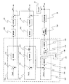
次に、図4により温度制御手段230の演算について説明を行う。
一点鎖線で囲まれた部分は温度制御手段230における制御演算部のブロック図である。
第1の制御演算部400は熱交換器20の下流に配置された第1の温度センサ110の値をフィードバックし目標値と加減算器410により加減算される。
制御部420によりPID演算が行われ冷却制御部264を駆動して第1の温度センサ110の値を所定値となるよう制御する。
その後、フィルタ30と加熱部40および供給ダクト60を通過した後、露光装置300に配置された第2の温度センサ120の値をフィードバックし、第2の制御演算部500において目標値と加減算器510により加減算される。
制御部520によりPID演算が行われ駆動部262を駆動して第2の温度センサ120の値を所定値となるよう制御する。
ここで、制御部520の出力、すなわち操作量(MV)530は、第3の制御演算部600において目標値と加減算器610により加減算される。
さらに、制御部620によりP演算またはPI演算またはPID演算が行われ第1の制御演算部400の加減算器410に印加される。
さらに、第3の制御演算部600により第2の制御演算部500の操作量(MV)530が所定値となるよう冷却制御部264への操作量を制御するよう構成されてもよい。
この場合、第1の制御演算部400により露光装置300における熱負荷やその他に帰還ダクト70や流体供給装置100に重畳する熱外乱を除去し第1の温度センサ110の値が所定値となるよう制御される。
さらに、第2の制御演算部500によりケミカルフィルタ30で発生する温度外乱や供給ダクト60より重畳する環境変化や露光装置内の負荷変動等による外乱に対して露光装置300の第2の温度センサ120の値が所定値となるよう制御される。
第3の制御演算部600によりに第2の制御演算部の操作量(MV)530が大きい時、すなわち加熱部40の加熱能力が所定値以上に必要とされるときは、第3の制御演算部600からの出力により冷却制御部264の冷却能力を低下させる。
加熱部40の加熱能力が所定値以下を必要とされるときは、第3の制御演算部600からの出力により冷却制御部264の冷却能力を向上させるよう制御される。
このため、第1の制御演算部400と第2の制御演算部500は第3の制御演算部600により相互に関係して制御され、各種温度外乱が加熱部40の加熱能力を超える大きな外乱となった場合でも冷却制御部264の能力を変更する。
これにより、常に高精度な温度制御を行うことが可能となる。
更に、露光装置300の中に第3の温度センサ130を配置し、第4の制御演算部700において目標値と加減算器710により加減算される。
制御部720によりPID演算が行われ駆動部268を駆動して第3の温度センサ130の値を所定値となるよう制御してもよい。
制御演算を行う温度制御手段230は露光装置300とは別の制御盤200に配置されているため露光装置300のフットプリントを削減することが可能となる。
従って、本実施例の露光システムによれば、露光装置のフットプリントを抑制しつつ高精度な温度安定性を有する。
Next, the calculation of the temperature control means 230 will be described with reference to FIG.
A portion surrounded by an alternate long and short dash line is a block diagram of a control calculation unit in the temperature control means 230.
The first
PID calculation is performed by the
Thereafter, after passing through the
PID calculation is performed by the
Here, the output of the
Further, the
Further, the operation amount to the
In this case, the first
Further, the
When the operation amount (MV) 530 of the second control calculation unit is large by the third
When the heating capacity of the
For this reason, the 1st
This makes it possible to always perform highly accurate temperature control.
Further, the
The
Since the temperature control means 230 for performing the control calculation is disposed on the
Therefore, according to the exposure system of the present embodiment, highly accurate temperature stability is achieved while suppressing the footprint of the exposure apparatus.
次に、本発明の実施例2の露光システムについて説明する。
図5は本発明の実施例2の露光システムの構成図である。
本実施例2は、基板であるウェハ315を露光する露光装置300と、露光装置300に流路を介して流体を供給する流体供給装置100と、を有する露光システムである。
流体供給装置100は、露光装置300を介して流体を流すための送流手段10と、流体の温度を調整する第1の温度調整手段である熱交換器20と、を有する。
さらに、流体供給装置100内において第1の温度調整手段である熱交換器20の下流に配され、流体の温度を計測し、該計測された温度の情報を第1の温度調整手段の制御に供する第1の温度計測手段である第1の温度センサ110を有する。
露光装置300は、流体供給装置100から供給される流体の温度を計測する第2の温度計測手段である第2の温度センサ120を有する。
第1の温度調整手段は、前記第1の温度計測手段により計測された温度の情報と前記第2の温度計測手段により計測された温度の情報とに基づき、前記流体の温度を調整する。第1の温度調整手段は、流体を冷却する冷却手段である冷却制御部264を有する。
本実施例2において、露光装置300は、クリーンルーム内に設置され、流体供給装置100は、クリーンルーム外に設置されている。
Next, an exposure system according to Example 2 of the present invention will be described.
FIG. 5 is a block diagram of an exposure system according to Embodiment 2 of the present invention.
The second embodiment is an exposure system that includes an
The
Furthermore, it is disposed downstream of the
The
The first temperature adjusting unit adjusts the temperature of the fluid based on the temperature information measured by the first temperature measuring unit and the temperature information measured by the second temperature measuring unit. The first temperature adjusting means includes a
In the second embodiment, the
実施例2における流体は液体で、実施例1と同様の機能を有する機器は同じ番号として説明を割愛する。
露光装置300と流体供給装置100は供給配管62と帰還配管72により接続されている。
流体供給装置100より露光装置300に供給する液体は、例えば純水や、防錆処理剤を含んだクーラント液、または電気絶縁性の高いフッ素系不活性液体を使用してもよい。
熱交換器20に戻って来る液体は露光装置300における熱を回収しているため温度が上昇している。第1の温度センサが所定値となるよう冷却制御部264が制御される。
タンク32を通過した後にポンプ12により供給配管62を通して露光装置300に液体が供給され、第2の温度センサ120により供給温度が計測される。
第2の温度センサ120は温度検出手段220によりディジタル信号に変換され、温度制御手段230に信号が伝達される。
温度制御手段230は第2の温度センサ120を所定値とするための操作量を演算し、冷却制御手段264を調整して熱交換器における交換熱量を制御する。
この構成により、制御演算を行う温度制御手段230や、冷却制御部264や保護機器である遮断機256が露光装置300とは別の制御盤200に配置されているため露光装置300のフットプリントを大幅に削減することが可能となる。
尚、制御盤200は、流体供給装置100とは別の筐体に配置してもよいし、流体供給装置100の内部に配置してもよい。
The fluid in the second embodiment is a liquid, and devices having the same functions as those in the first embodiment are not described as the same numbers.
The
As the liquid supplied from the
Since the liquid returning to the
After passing through the
The
The
With this configuration, the temperature control means 230 that performs control calculation, the cooling
Note that the
次に、本発明の実施例3の露光システムについて説明する。
実施例3では、図5の実施例2における露光装置300において、更に加熱器50と第3の温度センサ130を有する。
本実施例3は、基板であるウェハ315を露光する露光装置300と、露光装置300に流路を介して流体を供給する流体供給装置100と、を有する露光システムである。
流体供給装置100は、露光装置300を介して流体を流すための送流手段10と、流体の温度を調整する第1の温度調整手段である熱交換器20と、を有する。
さらに、流体供給装置100内において第1の温度調整手段である熱交換器20の下流に配され、流体の温度を計測し、該計測された温度の情報を第1の温度調整手段の制御に供する第1の温度計測手段である第1の温度センサ110を有する。
露光装置300は、流体供給装置100から供給される流体の温度を計測する第2の温度計測手段である第2の温度センサ120を有する。
露光装置300は、露光装置300内において第2の温度計測手段の下流に配され、流体の温度を調整する第2の温度調整手段である加熱器40を有する。
さらに、露光装置300内において第1の温度調整手段の下流に配され、流体の温度を計測し、該計測された温度の情報を前記第2の温度調整手段の制御に供する第3の温度計測手段である第3の温度センサ130を有する。
第1の温度調整手段は、第1の温度計測手段により計測された温度の情報と第2の温度計測手段により計測された温度の情報とに基づき、前記流体の温度を調整する。
第2の温度調整手段は、第3の温度計測手段により計測された温度の情報に基づき、前記流体の温度を調整する。
制御手段である温度制御手段230は、第1の温度調整手段の動作を制御する第1の制御演算部400、第2の温度調整手段の動作を制御する第2の制御演算部500、第2の制御演算部500の出力に応じた出力を行う第3の制御演算部600と、を有する。
第1の制御演算部は、第1の温度計測手段により計測された温度の情報と、第3の制御演算部の出力とに基づき、前記第1の温度調整手段の動作を制御する。
第1の温度調整手段は、前記流体を冷却する冷却手段を有し第2の温度調整手段は、前記流体を加熱する加熱手段を有する。
本実施例3において、露光装置300はクリーンルーム内に設置され、流体供給装置100はクリーンルーム外に設置されている。
Next, an exposure system according to Embodiment 3 of the present invention will be described.
In the third embodiment, the
The third embodiment is an exposure system that includes an
The
Furthermore, it is disposed downstream of the
The
The
Further, a third temperature measurement is arranged in the
The first temperature adjusting means adjusts the temperature of the fluid based on the temperature information measured by the first temperature measuring means and the temperature information measured by the second temperature measuring means.
The second temperature adjusting means adjusts the temperature of the fluid based on the temperature information measured by the third temperature measuring means.
The temperature control means 230, which is a control means, includes a first
The first control calculation unit controls the operation of the first temperature adjustment unit based on the temperature information measured by the first temperature measurement unit and the output of the third control calculation unit.
The first temperature adjusting means has a cooling means for cooling the fluid, and the second temperature adjusting means has a heating means for heating the fluid.
In the third embodiment, the
先に述べたウェハステージやレチクルステージまたは投影露光系では、アクチュエータの発熱や外部からの熱外乱に対し0.01℃以下の温度安定性が要求される場合があるため供給する液体の温度もより高精度に制御する必要がある。
第3の温度センサ130からの信号を温度検出手段220によりディジタル信号に変換し、温度制御手段230に信号を伝達する。
温度制御手段230は第3の温度センサ130を所定値とするための操作量を演算し駆動部268を通して加熱器50を調整するよう構成される。
この場合も、制御演算を行う温度制御手段230や加熱器50を駆動するための遮断器260、駆動部268が露光装置300とは別の制御盤200に配置される。
このため、露光装置300のフットプリントを大幅に削減することが可能となり、露光空間310に供給する液体の温度を極めて安定に制御することが可能となる。
In the above-described wafer stage, reticle stage, or projection exposure system, temperature stability of 0.01 ° C. or less may be required for the heat generation of the actuator or external thermal disturbance, so the temperature of the liquid to be supplied is also higher. It is necessary to control with high accuracy.
A signal from the
The temperature control means 230 is configured to calculate an operation amount for setting the
Also in this case, the temperature control means 230 for performing the control calculation, the
For this reason, the footprint of the
次に、図6により温度制御手段230の演算について説明を行う。
一点鎖線で囲まれた部分は温度制御手段230における制御演算部のブロック図である。
第1の制御演算部400は、熱交換器20の下流に配置された第1の温度センサ110の値をフィードバックし目標値と加減算器410により加減算される。
このため、制御部420によりPID演算が行われ冷却制御部264を駆動して第1の温度センサ110の値を所定値となるよう制御する。
その後、タンク32とポンプ12および供給配管62を通過した後、露光装置300に配置された第2の温度センサ130の値をフィードバックし、第2の制御演算部500において目標値と加減算器510により加減算される。
このため、制御部520によりPID演算が行われ駆動部268を駆動して第2の温度センサ130の値を所定値となるよう制御する。
ここで、制御部520の出力、すなわち操作量(MV)530は、第3の制御演算部600において目標値と加減算器610により加減算される。
制御部620によりP演算またはPI演算またはPID演算が行われ第1の制御演算部400の加減算器410に印加される。
さらに、第3の制御演算部600により第2の制御演算部500の操作量(MV)530が所定値となるよう冷却制御部264への操作量を制御するよう構成されてもよい。
Next, the calculation of the temperature control means 230 will be described with reference to FIG.
A portion surrounded by an alternate long and short dash line is a block diagram of a control calculation unit in the temperature control means 230.
The first
For this reason, PID calculation is performed by the
Thereafter, after passing through the
Therefore, PID calculation is performed by the
Here, the output of the
The
Further, the operation amount to the
この場合、第1の制御演算部400により露光装置300における熱負荷やその他に帰還配管72や流体供給装置100に重畳する熱外乱を除去し第1の温度センサ110の値が所定値となるよう制御される。
第2の制御演算部500によりポンプ12の発熱や供給配管62より重畳する環境変化や露光装置内の負荷変動等による外乱に対して露光装置300の第2の温度センサ120の値が所定値となるよう制御される。
第3の制御演算部600によりに第2の制御演算部の操作量(MV)530が大きい時、すなわち加熱部50の加熱能力が所定値以上に必要とされるときは第3の制御演算部600からの出力により冷却制御部264の冷却能力を低下させる。
加熱部50の加熱能力が所定値以下を必要とされるときは第3の制御演算部600からの出力により冷却制御部264の冷却能力を向上させるよう制御される。
このため、第1の制御演算部400と第2の制御演算部500は第3の制御演算部600により相互に関係して制御され、各種温度外乱が加熱部50の加熱能力を超える大きな外乱となった場合でも冷却制御部264の能力を変更する。
これにより、常に高精度な温度制御を行うことが可能となる。
制御演算を行う温度制御手段230は露光装置300とは別の制御盤200に配置されているため露光装置300のフットプリントを削減することが可能となる。
従って、本実施例の露光システムによれば、露光装置のフットプリントを抑制しつつ高精度な温度安定性を有する。
In this case, the first
The value of the
When the operation amount (MV) 530 of the second control calculation unit is large by the third
When the heating capacity of the
For this reason, the 1st
This makes it possible to always perform highly accurate temperature control.
Since the temperature control means 230 for performing the control calculation is disposed on the
Therefore, according to the exposure system of the present embodiment, highly accurate temperature stability is achieved while suppressing the footprint of the exposure apparatus.
次に、図8及び図9を参照して、上述の露光装置を利用したデバイス製造方法の実施例を説明する。
図8は、デバイス(ICやLSIなどの半導体チップ、LCD、CCD等)の製造を説明するためのフローチャートである。ここでは、半導体チップの製造方法を例に説明する。
上述の露光システムを用いてウェハを露光する工程と、露光されたウェハを現像する工程とを備え、具体的には、以下の工程から成る。
ステップ1(回路設計)では半導体デバイスの回路設計を行う。
ステップ2(マスク製作)では設計した回路パターンに基づいてマスク(原版またはレチクルともいう)を製作する。
ステップ3(ウェハ製造)ではシリコン等の材料を用いてウェハ(基板ともいう)を製造する。
ステップ4(ウェハプロセス)は前工程と呼ばれ、マスクとウェハを用いて、上記の露光装置によりリソグラフィ技術を利用してウェハ上に実際の回路を形成する。
ステップ5(組立)は、後工程と呼ばれ、ステップ4によって作製されたウェハを用いて半導体チップ化する工程であり、アッセンブリ工程(ダイシング、ボンディング)、パッケージング工程(チップ封入)等の組み立て工程を含む。
ステップ6(検査)では、ステップ5で作製された半導体デバイスの動作確認テスト、耐久性テスト等の検査を行う。
こうした工程を経て半導体デバイスが完成し、それが出荷(ステップ7)される。
Next, an embodiment of a device manufacturing method using the above-described exposure apparatus will be described with reference to FIGS.
FIG. 8 is a flowchart for explaining how to fabricate devices (ie, semiconductor chips such as IC and LSI, LCDs, CCDs, and the like). Here, a semiconductor chip manufacturing method will be described as an example.
The method comprises the steps of exposing a wafer using the exposure system described above and developing the exposed wafer, and specifically comprises the following steps.
In step 1 (circuit design), a semiconductor device circuit is designed.
In step 2 (mask production), a mask (also referred to as an original plate or a reticle) is produced based on the designed circuit pattern.
In step 3 (wafer manufacture), a wafer (also referred to as a substrate) is manufactured using a material such as silicon.
Step 4 (wafer process) is called a pre-process, and an actual circuit is formed on the wafer using the mask and the wafer by the above exposure apparatus using the lithography technique.
Step 5 (assembly) is referred to as a post-process, and is a process for forming a semiconductor chip using the wafer produced in step 4, and an assembly process such as an assembly process (dicing, bonding), a packaging process (chip encapsulation), or the like. including.
In step 6 (inspection), the semiconductor device manufactured in
Through these steps, a semiconductor device is completed and shipped (step 7).
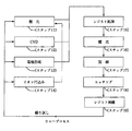
図9は、ステップ4のウェハプロセスの詳細なフローチャートである。
ステップ11(酸化)では、ウェハの表面を酸化させる。
ステップ12(CVD)では、ウェハの表面に絶縁膜を形成する。
ステップ13(電極形成)では、ウェハに電極を形成する。
ステップ14(イオン打込み)では、ウェハにイオンを打ち込む。
ステップ15(レジスト処理)では、ウェハに感光剤を塗布する。
ステップ16(露光)では、上述の露光システムを用い、マスクのパターンを介してウェハを露光する。
ステップ17(現像)では、露光したウェハを現像する。
ステップ18(エッチング)では、現像したレジスト像以外の部分を削り取る。
ステップ19(レジスト剥離)では、エッチングが済んで不要となったレジストを取り除く。
これらのステップを繰り返し行うことによってウェハ上に多重に回路パターンが形成される。
FIG. 9 is a detailed flowchart of the wafer process in Step 4.
In step 11 (oxidation), the surface of the wafer is oxidized.
In step 12 (CVD), an insulating film is formed on the surface of the wafer.
In step 13 (electrode formation), an electrode is formed on the wafer.
In step 14 (ion implantation), ions are implanted into the wafer.
In step 15 (resist process), a photosensitive agent is applied to the wafer.
Step 16 (exposure) uses the exposure system described above to expose the wafer through the mask pattern.
In step 17 (development), the exposed wafer is developed.
In step 18 (etching), portions other than the developed resist image are removed.
In step 19 (resist stripping), the resist that has become unnecessary after the etching is removed.
By repeatedly performing these steps, multiple circuit patterns are formed on the wafer.
10 ファン 20 熱交換器
30 ケミカルフィルタ 40、50 加熱器
60 供給ダクト 70 帰還ダクト
100 流体供給装置
110 第1の温度センサ 120 第2の温度センサ
200 制御盤
210,220 温度検出手段 230 温度制御手段
234 制御演算部 240 駆動手段
300 露光装置 310 露光空間
10
DESCRIPTION OF
234
Claims (11)
前記流体供給装置は、
前記露光装置を介して前記流体を流すための送流手段と、
前記流体の温度を調整する第1の温度調整手段と、
前記流体供給装置内において前記第1の温度調整手段の下流に配され、前記流体中の不要物を除去する除去手段と、
前記第1の温度調整手段と前記除去手段との間に配され、前記流体の温度を計測し、該計測された温度の情報を前記第1の温度調整手段の制御に供する第1の温度計測手段と、前記流体供給装置内において前記除去手段の下流に配され、前記流体の温度を調整する第2の温度調整手段と、
を有し、
前記露光装置は、
前記第2の温度調整手段の下流に配されて前記流体供給装置から供給される前記流体の温度を計測する第2の温度計測手段、
を有し、
前記露光システムは、
前記第1の温度計測手段により計測された温度の情報に基づいて前記第1の温度調整手段の動作を制御する第1の制御演算部と、
前記第2の温度計測手段により計測された温度の情報に基づいて前記第2の温度調整手段の動作を制御する第2の制御演算部と、
前記第2の制御演算部から前記第2の温度調整手段に対して出力される操作量と目標操作量との偏差に応じた出力を行う第3の制御演算部と、
を有し、
前記第1の制御演算部は、前記第1の温度計測手段により計測された温度の情報と、前記第3の制御演算部の出力とに基づき、前記第1の温度調整手段の動作を制御する、ことを特徴とする露光システム。 An exposure system comprising: an exposure apparatus that exposes a substrate; and a fluid supply apparatus that supplies fluid to the exposure apparatus via a flow path,
The fluid supply device includes:
A flow means for flowing the fluid through the exposure apparatus;
First temperature adjusting means for adjusting the temperature of the fluid;
A removing means disposed downstream of the first temperature adjusting means in the fluid supply device, for removing unnecessary substances in the fluid;
A first temperature measurement which is arranged between the first temperature adjusting means and the removing means, measures the temperature of the fluid, and provides information on the measured temperature to control the first temperature adjusting means. And a second temperature adjusting means that is arranged downstream of the removing means in the fluid supply device and adjusts the temperature of the fluid;
Have
The exposure apparatus includes:
A second temperature measuring means arranged downstream of the second temperature adjusting means and measuring the temperature of the fluid supplied from the fluid supply device;
Have
The exposure system includes:
A first control calculation unit that controls the operation of the first temperature adjusting unit based on the temperature information measured by the first temperature measuring unit;
A second control calculation unit for controlling the operation of the second temperature adjusting unit based on the temperature information measured by the second temperature measuring unit;
A third control calculation unit that performs output in accordance with a deviation between an operation amount output from the second control calculation unit to the second temperature adjustment unit and a target operation amount ;
Have
The first control calculation unit controls the operation of the first temperature adjustment unit based on the temperature information measured by the first temperature measurement unit and the output of the third control calculation unit. An exposure system characterized by that.
前記第2の温度調整手段は、前記流体を加熱する加熱手段を有する、The second temperature adjusting means has a heating means for heating the fluid.
ことを特徴とする請求項1に記載の露光システム。The exposure system according to claim 1, wherein:
前記露光装置における前記第2の温度計測手段の下流に配され、該流体の温度を調整する第3の温度調整手段と、A third temperature adjusting means arranged downstream of the second temperature measuring means in the exposure apparatus to adjust the temperature of the fluid;
前記露光装置における前記第3の温度調整手段の下流に配され、該流体の温度を計測する第3の温度計測手段と、A third temperature measuring means arranged downstream of the third temperature adjusting means in the exposure apparatus and measuring the temperature of the fluid;
を有し、Have
前記制御手段は、The control means includes
前記第3の温度計測手段により計測された温度の情報に基づき、前記第3の温度調整手段の動作を制御する第4の制御演算部、A fourth control calculation unit for controlling the operation of the third temperature adjusting unit based on the temperature information measured by the third temperature measuring unit;
を有する、Having
ことを特徴とする請求項1または2に記載の露光システム。The exposure system according to claim 1 or 2, wherein
前記液体供給装置は、The liquid supply device includes:
前記露光装置を介して前記液体を流すための送流手段と、A flow means for flowing the liquid through the exposure apparatus;
前記液体の温度を調整する第1の温度調整手段と、First temperature adjusting means for adjusting the temperature of the liquid;
前記液体供給装置内において前記第1の温度調整手段の下流に配され、前記液体の温度を計測し、該計測された温度の情報を前記第1の温度調整手段の制御に供する第1の温度計測手段と、A first temperature which is arranged downstream of the first temperature adjusting means in the liquid supply device, measures the temperature of the liquid, and provides information on the measured temperature to control of the first temperature adjusting means. Measuring means;
前記液体供給装置内において前記第1の温度調整手段の下流に配されるタンクと、A tank disposed downstream of the first temperature adjusting means in the liquid supply device;
を有し、Have
前記露光装置は、The exposure apparatus includes:
前記第1の温度調整手段の下流に配されて前記液体供給装置から供給される前記液体の温度を計測する第2の温度計測手段と、A second temperature measuring means arranged downstream of the first temperature adjusting means and measuring the temperature of the liquid supplied from the liquid supply device;
前記露光装置内において前記第2の温度計測手段の下流に配され、前記液体の温度を調整する第2の温度調整手段と、A second temperature adjusting means arranged downstream of the second temperature measuring means in the exposure apparatus for adjusting the temperature of the liquid;
前記露光装置内において前記第2の温度調整手段の下流に配され、前記液体の温度を計測し、該計測された温度の情報を前記第2の温度調整手段の制御に供する第3の温度計測手段と、A third temperature measurement that is arranged downstream of the second temperature adjusting means in the exposure apparatus, measures the temperature of the liquid, and uses the measured temperature information to control the second temperature adjusting means. Means,
を有し、Have
前記第1の温度調整手段は、前記第1の温度計測手段により計測された温度の情報と前記第2の温度計測手段により計測された温度の情報とに基づき、前記液体の温度を調整し、The first temperature adjusting means adjusts the temperature of the liquid based on the temperature information measured by the first temperature measuring means and the temperature information measured by the second temperature measuring means,
前記第2の温度調整手段は、前記第3の温度計測手段により計測された温度の情報に基づき、前記液体の温度を調整する、The second temperature adjusting means adjusts the temperature of the liquid based on the temperature information measured by the third temperature measuring means;
ことを特徴とする露光システム。An exposure system characterized by that.
前記第2の温度調整手段は、前記流体を加熱する加熱手段を有する、The second temperature adjusting means has a heating means for heating the fluid.
ことを特徴とする請求項6に記載の露光システム。The exposure system according to claim 6.
ことを特徴とする請求項6または7に記載の露光システム。The exposure system according to claim 6 or 7, wherein
ことを特徴とする請求項6乃至8のいずれか1項に記載の露光システム。The exposure system according to any one of claims 6 to 8, wherein:
前記流体供給装置は、The fluid supply device includes:
前記露光装置を介して前記流体を流すための送流手段と、A flow means for flowing the fluid through the exposure apparatus;
前記流体の温度を調整する第1の温度調整手段と、First temperature adjusting means for adjusting the temperature of the fluid;
前記流体供給装置内において前記第1の温度調整手段の下流に配され、前記流体の温度を計測する第1の温度計測手段と、A first temperature measuring means disposed downstream of the first temperature adjusting means in the fluid supply device and measuring the temperature of the fluid;
を有し、Have
前記露光装置は、The exposure apparatus includes:
前記第1の温度調整手段の下流に配されて前記流体供給装置から供給される前記流体の温度を調整する第2の温度調整手段と、Second temperature adjusting means arranged downstream of the first temperature adjusting means and adjusting the temperature of the fluid supplied from the fluid supply device;
前記第2の温度調整手段の下流に配されて、前記流体の温度を計測する第2の温度計測手段と、A second temperature measuring means arranged downstream of the second temperature adjusting means for measuring the temperature of the fluid;
を有し、Have
前記露光システムは、The exposure system includes:
前記第1の温度計測手段により計測された温度の情報に基づいて前記第1の温度調整手段の動作を制御する第1の制御演算部と、A first control calculation unit that controls the operation of the first temperature adjusting unit based on the temperature information measured by the first temperature measuring unit;
前記第2の温度計測手段により計測された温度の情報に基づいて前記第2の温度調整手段の動作を制御する第2の制御演算部と、A second control calculation unit for controlling the operation of the second temperature adjusting unit based on the temperature information measured by the second temperature measuring unit;
前記第2の制御演算部から前記第2の温度調整手段に対して出力される操作量と目標操作量との偏差に応じた出力を行う第3の制御演算部と、 A third control calculation unit that performs output in accordance with a deviation between an operation amount output from the second control calculation unit to the second temperature adjustment unit and a target operation amount;
を有し、Have
前記第1の制御演算部は、前記第1の温度計測手段により計測された温度の情報と、前記第3の制御演算部の出力とに基づき、前記第1の温度調整手段の動作を制御する、ことを特徴とする露光システム。The first control calculation unit controls the operation of the first temperature adjustment unit based on the temperature information measured by the first temperature measurement unit and the output of the third control calculation unit. An exposure system characterized by that.
該露光された基板を現像する工程と、Developing the exposed substrate;
を有することを特徴とするデバイス製造方法。A device manufacturing method comprising:
Priority Applications (5)
| Application Number | Priority Date | Filing Date | Title |
|---|---|---|---|
| JP2007146347A JP5207663B2 (en) | 2007-05-31 | 2007-05-31 | Exposure system and device manufacturing method |
| US12/118,254 US7760325B2 (en) | 2007-05-31 | 2008-05-09 | Exposure system and method for manufacturing device |
| TW097119912A TWI399619B (en) | 2007-05-31 | 2008-05-29 | Exposure system and method for manufacturing device |
| KR1020080050548A KR101037227B1 (en) | 2007-05-31 | 2008-05-30 | Exposure system and method for manufacturing device |
| KR1020110014567A KR20110036022A (en) | 2007-05-31 | 2011-02-18 | Exposure system and method for manufacturing device |
Applications Claiming Priority (1)
| Application Number | Priority Date | Filing Date | Title |
|---|---|---|---|
| JP2007146347A JP5207663B2 (en) | 2007-05-31 | 2007-05-31 | Exposure system and device manufacturing method |
Publications (3)
| Publication Number | Publication Date |
|---|---|
| JP2008300702A JP2008300702A (en) | 2008-12-11 |
| JP2008300702A5 JP2008300702A5 (en) | 2010-07-15 |
| JP5207663B2 true JP5207663B2 (en) | 2013-06-12 |
Family
ID=40173899
Family Applications (1)
| Application Number | Title | Priority Date | Filing Date |
|---|---|---|---|
| JP2007146347A Active JP5207663B2 (en) | 2007-05-31 | 2007-05-31 | Exposure system and device manufacturing method |
Country Status (4)
| Country | Link |
|---|---|
| US (1) | US7760325B2 (en) |
| JP (1) | JP5207663B2 (en) |
| KR (2) | KR101037227B1 (en) |
| TW (1) | TWI399619B (en) |
Families Citing this family (7)
| Publication number | Priority date | Publication date | Assignee | Title |
|---|---|---|---|---|
| WO2009100163A1 (en) * | 2008-02-05 | 2009-08-13 | Applied Materials, Inc. | Methods and apparatus for operating an electronic device manufacturing system |
| US9387428B2 (en) * | 2008-02-05 | 2016-07-12 | Applied Materials, Inc. | Systems and methods for treating flammable effluent gases from manufacturing processes |
| JP2010182834A (en) * | 2009-02-04 | 2010-08-19 | Nikon Corp | Method and apparatus of exposure, and method of manufacturing device |
| JP5641709B2 (en) * | 2009-04-23 | 2014-12-17 | キヤノン株式会社 | Device manufacturing apparatus and device manufacturing method |
| US9075408B2 (en) * | 2009-11-16 | 2015-07-07 | Applied Materials, Inc. | Energy savings and global gas emissions monitoring and display |
| US9207270B2 (en) * | 2012-08-31 | 2015-12-08 | Elwha Llc | Method and apparatus for measuring negawatt usage of an appliance |
| KR102247922B1 (en) * | 2019-04-29 | 2021-05-04 | 강용훈 | Cooling System for Curing Machine |
Family Cites Families (16)
| Publication number | Priority date | Publication date | Assignee | Title |
|---|---|---|---|---|
| JPS61160934A (en) * | 1985-01-10 | 1986-07-21 | Canon Inc | Projection optical device |
| WO1999012194A1 (en) | 1997-08-29 | 1999-03-11 | Nikon Corporation | Temperature adjusting method and aligner to which this method is applied |
| JPH11135429A (en) | 1997-08-29 | 1999-05-21 | Nikon Corp | Temperature control method and aligner using the method |
| JP2001244179A (en) * | 2000-02-29 | 2001-09-07 | Canon Inc | Aligner equipped with temperature controller, and method of manufacturing device |
| JP2002158170A (en) * | 2000-09-08 | 2002-05-31 | Nikon Corp | Aligner and method for fabricating device |
| JP3709338B2 (en) | 2000-11-22 | 2005-10-26 | 日本電気株式会社 | Mobile phone user setting information management method and user setting information management system |
| JP2003067058A (en) * | 2001-08-30 | 2003-03-07 | Canon Inc | Temperature controller and means for manufacturing device therewith |
| JP2003115440A (en) * | 2001-10-03 | 2003-04-18 | Canon Inc | Thermoregulator and non-interference thermoregulator, and aligner having them |
| JP2003133211A (en) * | 2001-10-26 | 2003-05-09 | Canon Inc | Device manufacturing apparatus and heating and cooling control method |
| JP2004128213A (en) * | 2002-10-02 | 2004-04-22 | Canon Inc | Temperature control system and aligner incorporating the same |
| JP2005142382A (en) | 2003-11-07 | 2005-06-02 | Canon Inc | Exposure apparatus |
| JP2006005135A (en) * | 2004-06-17 | 2006-01-05 | Canon Inc | Temperature adjusting apparatus and device manufacturing apparatus |
| JP2006041251A (en) * | 2004-07-28 | 2006-02-09 | Canon Inc | Exposure system |
| JP4418724B2 (en) * | 2004-09-17 | 2010-02-24 | キヤノン株式会社 | Exposure equipment |
| JP2006222165A (en) * | 2005-02-08 | 2006-08-24 | Canon Inc | Exposure device |
| JP4835970B2 (en) * | 2005-05-24 | 2011-12-14 | 株式会社ニコン | Adjustment method |
-
2007
- 2007-05-31 JP JP2007146347A patent/JP5207663B2/en active Active
-
2008
- 2008-05-09 US US12/118,254 patent/US7760325B2/en not_active Expired - Fee Related
- 2008-05-29 TW TW097119912A patent/TWI399619B/en not_active IP Right Cessation
- 2008-05-30 KR KR1020080050548A patent/KR101037227B1/en active IP Right Grant
-
2011
- 2011-02-18 KR KR1020110014567A patent/KR20110036022A/en not_active Application Discontinuation
Also Published As
| Publication number | Publication date |
|---|---|
| TW200912554A (en) | 2009-03-16 |
| KR101037227B1 (en) | 2011-05-25 |
| KR20080106074A (en) | 2008-12-04 |
| TWI399619B (en) | 2013-06-21 |
| JP2008300702A (en) | 2008-12-11 |
| US7760325B2 (en) | 2010-07-20 |
| US20090011376A1 (en) | 2009-01-08 |
| KR20110036022A (en) | 2011-04-06 |
Similar Documents
| Publication | Publication Date | Title |
|---|---|---|
| JP5207663B2 (en) | Exposure system and device manufacturing method | |
| US7283199B2 (en) | Exposure apparatus, and device manufacturing method | |
| US7317505B2 (en) | Exposure apparatus and device manufacturing method | |
| US7565926B2 (en) | Heat exchange method and heat exchange apparatus | |
| US9256141B2 (en) | Exposure apparatus, device manufacturing method using same, and gas supply device | |
| JP2009094163A (en) | Temperature regulating apparatus, exposure apparatus, and device manufacturing method | |
| EP1670040A1 (en) | Projection exposure device, projection exposure method, and device manufacturing method | |
| US7652748B2 (en) | Exposure apparatus and device manufacturing method | |
| JP4614386B2 (en) | Positioning apparatus, exposure apparatus, and device manufacturing method using the same | |
| KR20090094758A (en) | Regulating device, exposure apparatus and device manufacturing method | |
| US8115425B2 (en) | Driving apparatus, industrial instrument, exposure apparatus, and device manufacturing method | |
| JP2004134566A (en) | Device manufacturing apparatus | |
| JPH10149970A (en) | Treating device and production method of device | |
| JP2010050237A (en) | Exposure device and device manufacturing method | |
| JPH1126376A (en) | Apparatus for projection exposure and manufacturing device | |
| JP2004247688A (en) | Refrigerant supplying device | |
| JP2010045300A (en) | Exposure device | |
| JP2004158510A (en) | Device manufacturing apparatus | |
| JP2001143986A (en) | Device manufacturing apparatus | |
| JP2005268324A (en) | Temperature controller, exposure device, and method for manufacturing device |
Legal Events
| Date | Code | Title | Description |
|---|---|---|---|
| RD01 | Notification of change of attorney |
Free format text: JAPANESE INTERMEDIATE CODE: A7421 Effective date: 20090406 |
|
| RD04 | Notification of resignation of power of attorney |
Free format text: JAPANESE INTERMEDIATE CODE: A7424 Effective date: 20100201 |
|
| A521 | Request for written amendment filed |
Free format text: JAPANESE INTERMEDIATE CODE: A523 Effective date: 20100528 |
|
| A621 | Written request for application examination |
Free format text: JAPANESE INTERMEDIATE CODE: A621 Effective date: 20100528 |
|
| RD01 | Notification of change of attorney |
Free format text: JAPANESE INTERMEDIATE CODE: A7421 Effective date: 20100630 |
|
| A977 | Report on retrieval |
Free format text: JAPANESE INTERMEDIATE CODE: A971007 Effective date: 20120308 |
|
| A131 | Notification of reasons for refusal |
Free format text: JAPANESE INTERMEDIATE CODE: A131 Effective date: 20120313 |
|
| A521 | Request for written amendment filed |
Free format text: JAPANESE INTERMEDIATE CODE: A523 Effective date: 20120514 |
|
| TRDD | Decision of grant or rejection written | ||
| A01 | Written decision to grant a patent or to grant a registration (utility model) |
Free format text: JAPANESE INTERMEDIATE CODE: A01 Effective date: 20130122 |
|
| A61 | First payment of annual fees (during grant procedure) |
Free format text: JAPANESE INTERMEDIATE CODE: A61 Effective date: 20130219 |
|
| FPAY | Renewal fee payment (event date is renewal date of database) |
Free format text: PAYMENT UNTIL: 20160301 Year of fee payment: 3 |
|
| R151 | Written notification of patent or utility model registration |
Ref document number: 5207663 Country of ref document: JP Free format text: JAPANESE INTERMEDIATE CODE: R151 |
|
| FPAY | Renewal fee payment (event date is renewal date of database) |
Free format text: PAYMENT UNTIL: 20160301 Year of fee payment: 3 |