JP5206076B2 - Display device - Google Patents
Display device Download PDFInfo
- Publication number
- JP5206076B2 JP5206076B2 JP2008093157A JP2008093157A JP5206076B2 JP 5206076 B2 JP5206076 B2 JP 5206076B2 JP 2008093157 A JP2008093157 A JP 2008093157A JP 2008093157 A JP2008093157 A JP 2008093157A JP 5206076 B2 JP5206076 B2 JP 5206076B2
- Authority
- JP
- Japan
- Prior art keywords
- display
- image
- case member
- display panel
- display device
- Prior art date
- Legal status (The legal status is an assumption and is not a legal conclusion. Google has not performed a legal analysis and makes no representation as to the accuracy of the status listed.)
- Active
Links
- 230000002093 peripheral effect Effects 0.000 claims description 21
- 239000004973 liquid crystal related substance Substances 0.000 description 6
- 230000000694 effects Effects 0.000 description 1
- 238000005401 electroluminescence Methods 0.000 description 1
- 239000002184 metal Substances 0.000 description 1
Images


Description
この発明は、表示パネルにより表示された画像の実像を、前記表示パネルとは異なる位置に結像させ、その像を観察させるようにした表示装置に関する。 The present invention relates to a display device in which a real image of an image displayed on a display panel is formed at a position different from that of the display panel and the image is observed.
液晶表示パネル等の表示パネルにより表示された画像を前記表示パネルとは異なる位置に表示する表示装置としては、従来、表示パネルにより表示された画像を、前記表示パネルとは異なる位置に配置されたスクリーンに投影することにより擬似立体画像を表示するものがある(特許文献1、特許文献2参照)。
しかし、上記従来の表示装置による表示像は、スクリーン上に投影された像であり、前記スクリーンとに共に観察されるため、立体感に乏しい。 However, the display image by the conventional display device is an image projected on the screen and is observed together with the screen, so that the stereoscopic effect is poor.
この発明は、表示パネルにより表示された画像の実像を、前記表示パネルとは異なる空間に浮いた像のように表示することができる表示装置を提供することを目的としたものである。 An object of the present invention is to provide a display device capable of displaying a real image of an image displayed on a display panel as an image floating in a space different from the display panel.
請求項1に記載の発明に係る表示装置は、全周が透明な円筒状の筒部を有するケース部材と、画像の表示面が、前記筒部の径方向に対して垂直になるように、前記筒部内の一端側に配置された画像表示手段と、を備え、前記画像表示手段は、前記表示面の法線から前記筒部の中心線に沿う方向へ予め定めた角度だけ傾いた方向に指向性を有した前記画像としての光を前記表示面から出射するとともに、前記画像としての光が前記筒部の内周面に投射されるように配置されており、前記筒部は、前記内周面で反射した前記画像としての光が前記表示面よりも前記筒部の他端側の空間で結像するように前記画像としての光を反射させ、前記画像表示手段は、前記中心線を中心軸にして前記表示面が回転可能に配置されていることを特徴とする。
The display device according to the invention of
請求項2に記載の発明は、前記請求項1に記載の表示装置において、前記筒部は、前記表示面から該筒部の内周面に投射される前記画像としての光の少なくとも一部を前記内周面で反射するように形成されていることを特徴とする。 According to a second aspect of the present invention, in the display device according to the first aspect, the cylindrical portion receives at least part of the light as the image projected from the display surface onto the inner peripheral surface of the cylindrical portion. It is formed to reflect on the inner peripheral surface .
請求項3に記載の発明は、前記請求項2に記載の表示装置において、前記筒部は、前記中心線が前記表示面に一致するように配置されていることを特徴とする。 According to a third aspect of the present invention, in the display device according to the second aspect, the cylindrical portion is arranged so that the center line coincides with the display surface .
この発明の表示装置によれば、表示パネルにより表示された画像の実像を、前記表示パネルとは異なる空間に浮いた像のように表示することができる。 According to the display device of the present invention, the real image of the image displayed on the display panel can be displayed like an image floating in a space different from the display panel.
(第1の実施形態)
図1〜図4はこの発明の第1の実施例を示しており、図1は表示装置の一部切開斜視図、図2は前記表示装置の平面図、図3は前記表示装置の断面図である。
(First embodiment)
1 to 4 show a first embodiment of the present invention. FIG. 1 is a partially cut perspective view of a display device, FIG. 2 is a plan view of the display device, and FIG. 3 is a cross-sectional view of the display device. It is.
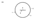
この表示装置は、図1〜図3のように、円筒状のケース部材1と、前記ケース部材1内の一端側に、画像の表示面6を前記ケース部材1の内周面に対向させ、且つ前記表示面6を前記ケース部材1の径方向に対して実質的に垂直にして配置され、表示画像に対応した光8を、前記表示面6から前記表示面6の法線方向6aに対して前記ケース部材1の他端方向に予め定めた角度θ傾いた方向に出射する表示パネル5とからなっている。
As shown in FIGS. 1 to 3, the display device has a
この実施例の表示装置において、前記ケース部材1は、全周が透明な円筒体2からなっており、前記表示パネル5は、前記円筒体2からなるケース部材1内の一端側に、前記表示面6を前記ケース部材1の予め定めた観察方向10とは反対側の内周面に対向させ、且つ前記表示面6を前記ケース部材1の径方向に対して実質的に垂直にするとともに、前記表示面6の中心位置を前記ケース部材1の中心線(円筒体2の前中心線)2aに一致させて配置され、前記ケース部材1の一端に設けられた表示パネル支持板3に固定されている。
In the display device of this embodiment, the
前記表示パネル5は、黒の背景中に画像を表示するものであり、例えば、液晶表示素子と前記液晶表示素子の表示面とは反対面に対向させて配置された面光源とからなる液晶表示パネル、或いは有機EL(エレクトロルミネッセンス)表示パネル等の自発光表示パネルからなっている。
The
なお、前記表示パネル5に前記液晶表示パネルを用いる場合は、前記面光源に、上記の方向(表示パネル5の表示面6の法線方向6aに対してケース部材1の他端方向に予め定めた角度θ傾いた方向)に向けて平行光を照射する指向性をもたせるか、或いは前記液晶表示素子の表示面側に、前記表示面からの出射光を上記の方向に屈折させるためのプリズムシート及び/またはレンズシート等を配置する。また、前記表示パネル5に前記自発光表示パネルを用いる場合は、その表示面側に、前記表示面からの出射光を平行な光にして上記の方向に出射させるプリズムシート及び/またはレンズシート等を配置する。
When the liquid crystal display panel is used for the
この表示装置は、前記表示パネル5に画像を表示させ、この表示パネル5の表示面6からの出射光8を、前記ケース部材1の内周面により反射し、前記ケース部材1内の前記表示パネル5よりも前記他端方向の空間に、前記表示パネル5の表示画像に対応した実像9を結像させ、その実像9を、前記ケース部材1の外周のうちの前記観察方向10から観察させる。
The display device displays an image on the
すなわち、前記ケース部材1内の一端側に配置された前記表示パネル5の表示面6から前記表示面6の法線方向6aに対して前記ケース部材1の他端方向に予め定めた角度θ傾いた方向に出射した光8は、前記透明な円筒体2からなるケース部材1の前記表示パネル5の表示面6に対向する側の内周面により、前記ケース部材1内の前記表示パネル5よりも前記他端方向の空間に向けて反射される。
That is, a predetermined angle θ is inclined in the other end direction of the
そして、前記ケース部材1の内周面は、凹面反射鏡の機能により、その反射面の曲率半径に対応した距離の位置に実像を結像させるため、前記ケース部材1内の前記表示パネル5よりも前記他端方向の空間に、前記実像9が結像する。
The inner peripheral surface of the
なお、この実施例の表示装置は、前記表示パネル5を、その表示面6を前記ケース部材1の中心線2aに一致させて配置し、前記ケース部材1の内周面の曲率半径を、前記ケース部材1の中心線2a上の位置に前記実像9を結像させるように設定したものであり、前記実像9は、前記表示パネル5の表示面を前記中心線2a方向に延長した面上に結像する。
In the display device of this embodiment, the
図4は、前記表示パネル5の表示面6側から見た表示画像7と、前記観察方向10から見た前記実像9とを示しており、前記表示パネル5の表示画像7は黒の背景中に表示されるため、前記実像9は、背景の無い空間に浮いて見える像である。
FIG. 4 shows a
なお、前記観察方向10から見た前記実像9は、前記表示パネル5の表示面6側から見た表示画像7に対して、前記ケース部材1の周方向に沿った方向において左右が反転した像であるが、前記表示パネル5はその表示面6を観察方向10とは反対側に向けて配置されているため、前記観察方向10から観察される実像9は、図4のように、前記表示パネル5の表示面6側から見た表示画像7と同じ向きの像である。
The
このように、上記表示装置は、前記ケース部材1内の一端側に配置された前記表示パネル5からの出射光8を前記ケース部材1の内周面により反射し、前記ケース部材1内の前記表示パネル5よりも前記他端方向の空間に前記表示パネル5の表示画像7に対応した実像9を結像させるものであるため、前記表示パネル5により表示された画像の実像を、前記表示パネル5とは異なる位置に、前記ケース部材1内の空間に浮いた像のように表示することができる。
Thus, the display device reflects the emitted
なお、上記実施例では、前記ケース部材1の内周面の曲率半径を、前記ケース部材1の中心線2a上の位置に前記実像9を結像させるように設定しているが、前記曲率半径は、前記ケース部材1の中心線2aから前記観察方向10またはその反対方向にずれた位置に前記実像9を結像させるように設定してもよく、また、前記表示パネル5は、上記実施例の位置(表示面6をケース部材1の中心線2a一致させた位置)に対して前記観察方向10またはその反対方向にずれた位置に配置してもよい。
In the above embodiment, the radius of curvature of the inner peripheral surface of the
また、上記実施例の表示装置は、全周が透明な円筒体2からなるケース部材1を備えたものであるが、ケース部材1は、少なくとも前記観察方向10に対向する側が透明であれば、前記観察方向10とは反対側の内周面に反射膜を形成するか、或いは前記反対側の周壁を金属板等の反射板により形成した円筒体からなるものでもよく、さらに、前記ケース部材1は、円筒状のものに限らず、前記観察方向10に対向する側が外部に開放した半円筒状のものでもよい。
Further, the display device of the above embodiment includes the
(第2の実施形態)
図5〜図7はこの発明の第2の実施例を示しており、図5は表示装置の一部切開斜視図、図6は前記表示装置の平面図である。なお、この実施例において、上記第1の実施例の表示装置に対応するものには図に同符号を付し、同一のものについてはその説明を省略する。
(Second Embodiment)
5 to 7 show a second embodiment of the present invention. FIG. 5 is a partially cut perspective view of the display device, and FIG. 6 is a plan view of the display device. In this embodiment, components corresponding to those of the display device of the first embodiment are denoted by the same reference numerals, and description of the same components is omitted.
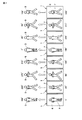
この表示装置は、全周が透明な円筒体2からなるケース部材1内の一端側に、表示画像に対応した光を表示面6の法線方向に対して前記ケース部材1の他端方向に予め定めた角度傾いた方向に出射する表示パネル5を、その表示面6を前記ケース部材1の内周面に対向させ、且つ前記表示面6を前記ケース部材1の径方向に対して実質的に垂直にして配置し、さらにこの表示パネル5を、前記ケース部材1の円筒の中心を軸として回転可能に設けたものであり、この実施例では、前記表示パネル5を、その表示面の中心位置を前記ケース部材1の中心線2aに一致させて前記中心線2a回りに回転可能に設け、さらに、前記ケース部材1の内周面の曲率半径を、前記ケース部材1の中心線2a上の位置に、前記表示パネル5の表示画像に対応した実像9を結像させるように設定している。
In this display device, light corresponding to a display image is applied to one end side of a
なお、この実施例では、前記ケース部材1の一端に設けられた表示パネル支持板3の内面上に、前記ケース部材1の中心線2aを中心として回転するターンテーブル4を設け、このターンテーブル4上に前記表示パネル5を固定している。
In this embodiment, a turntable 4 that rotates about the
そして、この表示装置では、前記表示パネル5を回転させ、前記表示パネル5が前記予め定めた角度回転する毎に、前記表示パネル5に、立体物の外周を前記予め定めた角度毎に分割した複数の方向から見た複数の画像を順次表示させるようにしている。
In this display device, the
この実施例の表示装置は、全周が透明な円筒体2からなる前記ケース部材1内に、前記表示パネル5を、前記ケース部材1の周方向に回転可能に設けているため、前記表示パネル5から出射し、前記ケース部材1の内周面により反射されて前記ケース部材1の空間内に結像した実像9を、前記ケース部材1の実質的に全周方向から観察することができる。
In the display device of this embodiment, the
また、この表示装置は、前記表示パネル5を、その表示面6を前記ケース部材1の中心線2aに一致させて前記中心線2a回りに回転可能に設け、前記ケース部材1の内周面の曲率半径を、前記ケース部材1の中心線2a上の位置に前記実像9を結像させるように設定しているため、前記実像9を、前記ケース部材1の全周のどの方向に対しても同じ大きさで表示することができる。
In addition, the display device is provided with the
さらに、この表示装置は、前記表示パネル5を、予め定めた角度の回転ピッチで間欠的に回転させ、前記表示パネル5が前記予め定めた角度回転する毎に、前記表示パネル5に、立体物の外周を前記予め定めた角度毎に分割した複数の方向から見た複数の画像を順次表示させるようにしているため、前記ケース部材1の周囲の各観察方向に対して、前記立体物を、その周囲から角度を変えて見たような実像9を表示することができる。
Further, the display device intermittently rotates the
図7は、この実施例の表示装置における前記表示パネル5の各回転角毎の表示面6側から見た表示画像7と、前記各回転角毎の前記表示パネル5の表示面6の向きとは反対方向から見た前記実像9とを示している。
FIG. 7 shows a
この表示例は、前記表示パネル5に、立体物の外周を図6のように45°の角度毎に分割した8つの方向から見た複数の画像を順次表示させた例であり、図7において、表示パネル5の下に記載した角度は、前記表示パネル5の表示面6の向きを示し、実像9の上に記載した角度は、前記実像9の観察方向を示している。
This display example is an example in which a plurality of images viewed sequentially from eight directions obtained by dividing the outer periphery of the three-dimensional object by 45 ° angles as shown in FIG. 6 are displayed on the
この実施例の表示装置において、前記表示パネル5に表示させる画像は、立体物の外周を他の角度毎に分割した複数の方向から見た複数の画像でもよく、前記表示パネル5に、立体物を前記45°よりも小さい角度毎に分割した複数の方向から見た複数の画像を順次表示させることにより、立体物を異なる方向から見たような実像9を、さらに多くの角度方向に対して表示することができる。
In the display device of this embodiment, the image displayed on the
なお、前記表示パネル5に各回転角毎に表示させる画像は、立体物を複数の方向それぞれから見た複数の画像以外の画像でもよく、例えば、前記各回転角毎に同じ画像を表示させることにより、前記ケース部材1の全周のどの方向に対しても同じ実像を表示することができる。
The image displayed on the
1…ケース部材、2…円筒体、4…ターンテーブル、5…表示パネル、6…表示面、7…表示パネルの表示画像、8…表示パネルからの出射光、9…実像、10…観察方向。
DESCRIPTION OF
Claims (3)
画像の表示面が、前記筒部の径方向に対して垂直になるように、前記筒部内の一端側に配置された画像表示手段と、
を備え、
前記画像表示手段は、前記表示面の法線から前記筒部の中心線に沿う方向へ予め定めた角度だけ傾いた方向に指向性を有した前記画像としての光を前記表示面から出射するとともに、前記画像としての光が前記筒部の内周面に投射されるように配置されており、
前記筒部は、前記内周面で反射した前記画像としての光が前記表示面よりも前記筒部の他端側の空間で結像するように前記画像としての光を反射させ、
前記画像表示手段は、前記中心線を中心軸にして前記表示面が回転可能に配置されていることを特徴とする表示装置。 A case member all around having a transparent cylindrical barrel portion,
Image display means arranged on one end side in the cylindrical portion so that an image display surface is perpendicular to the radial direction of the cylindrical portion;
With
The image display means emits light as the image having directivity in a direction inclined by a predetermined angle from a normal line of the display surface to a direction along the center line of the cylindrical portion, from the display surface. The light as the image is arranged so as to be projected onto the inner peripheral surface of the cylindrical portion ,
The cylindrical portion reflects the light as the image so that the light as the image reflected by the inner peripheral surface forms an image in a space on the other end side of the cylindrical portion with respect to the display surface,
The display device, wherein the image display means is arranged such that the display surface is rotatable about the center line as a center axis .
Priority Applications (1)
| Application Number | Priority Date | Filing Date | Title |
|---|---|---|---|
| JP2008093157A JP5206076B2 (en) | 2008-03-31 | 2008-03-31 | Display device |
Applications Claiming Priority (1)
| Application Number | Priority Date | Filing Date | Title |
|---|---|---|---|
| JP2008093157A JP5206076B2 (en) | 2008-03-31 | 2008-03-31 | Display device |
Publications (3)
| Publication Number | Publication Date |
|---|---|
| JP2009244728A JP2009244728A (en) | 2009-10-22 |
| JP2009244728A5 JP2009244728A5 (en) | 2010-12-09 |
| JP5206076B2 true JP5206076B2 (en) | 2013-06-12 |
Family
ID=41306657
Family Applications (1)
| Application Number | Title | Priority Date | Filing Date |
|---|---|---|---|
| JP2008093157A Active JP5206076B2 (en) | 2008-03-31 | 2008-03-31 | Display device |
Country Status (1)
| Country | Link |
|---|---|
| JP (1) | JP5206076B2 (en) |
Families Citing this family (2)
| Publication number | Priority date | Publication date | Assignee | Title |
|---|---|---|---|---|
| JP5494192B2 (en) * | 2010-04-30 | 2014-05-14 | カシオ計算機株式会社 | Display device |
| JP5643450B1 (en) * | 2013-08-22 | 2014-12-17 | 敏之 仁木 | Mirror that displays stereoscopic images |
Family Cites Families (6)
| Publication number | Priority date | Publication date | Assignee | Title |
|---|---|---|---|---|
| JPH0544810Y2 (en) * | 1985-03-06 | 1993-11-15 | ||
| JP3063300U (en) * | 1999-04-22 | 1999-10-29 | 株式会社三洋社 | Simulated image forming device |
| JP2001025036A (en) * | 1999-07-05 | 2001-01-26 | Minolta Co Ltd | Stereoscopic image display device |
| JP4843901B2 (en) * | 2004-02-05 | 2011-12-21 | 株式会社日立製作所 | Display device |
| JP4324845B2 (en) * | 2003-05-09 | 2009-09-02 | 芳晴 桃井 | Video display device |
| JP2005295325A (en) * | 2004-04-01 | 2005-10-20 | Seiko Epson Corp | Image display apparatus |
-
2008
- 2008-03-31 JP JP2008093157A patent/JP5206076B2/en active Active
Also Published As
| Publication number | Publication date |
|---|---|
| JP2009244728A (en) | 2009-10-22 |
Similar Documents
| Publication | Publication Date | Title |
|---|---|---|
| JP4267668B2 (en) | 3D image display device | |
| JP3955589B2 (en) | 3D display device | |
| JP6589890B2 (en) | Head-up display device | |
| JP2006512622A5 (en) | ||
| JP2011081309A (en) | Spatial video display device | |
| JP2016027487A5 (en) | ||
| JP2009031336A (en) | Projector | |
| RU2007108944A (en) | VISUAL DISPLAY DEVICE | |
| JP2013215560A (en) | Endoscope camera | |
| US8454168B2 (en) | Stereo display apparatus | |
| JP5206076B2 (en) | Display device | |
| JP2006308745A (en) | Liquid crystal display device | |
| WO2018043204A1 (en) | Display device | |
| JP6501066B2 (en) | Display device | |
| JP6696174B2 (en) | Display device | |
| MY137052A (en) | Spherical reflective screen with focus and method for manufacturing the same | |
| JP2006201611A (en) | Virtual image display type information display system | |
| JP2006085135A (en) | Stereoscopic display system | |
| WO2013114986A1 (en) | Surveillance camera with dome cover attached thereto, and dome cover | |
| JP2018194699A (en) | Display device, and array time display device | |
| JP2017083635A (en) | Display device | |
| JP5821518B2 (en) | Optical element and image display device | |
| JP6708198B2 (en) | Vehicle display | |
| JPWO2019028215A5 (en) | ||
| JP2009204423A (en) | Infrared imaging device |
Legal Events
| Date | Code | Title | Description |
|---|---|---|---|
| A521 | Request for written amendment filed |
Free format text: JAPANESE INTERMEDIATE CODE: A523 Effective date: 20101022 |
|
| A621 | Written request for application examination |
Free format text: JAPANESE INTERMEDIATE CODE: A621 Effective date: 20101022 |
|
| A977 | Report on retrieval |
Free format text: JAPANESE INTERMEDIATE CODE: A971007 Effective date: 20111116 |
|
| A131 | Notification of reasons for refusal |
Free format text: JAPANESE INTERMEDIATE CODE: A131 Effective date: 20111206 |
|
| A521 | Request for written amendment filed |
Free format text: JAPANESE INTERMEDIATE CODE: A523 Effective date: 20120206 |
|
| TRDD | Decision of grant or rejection written | ||
| A01 | Written decision to grant a patent or to grant a registration (utility model) |
Free format text: JAPANESE INTERMEDIATE CODE: A01 Effective date: 20130122 |
|
| A61 | First payment of annual fees (during grant procedure) |
Free format text: JAPANESE INTERMEDIATE CODE: A61 Effective date: 20130204 |
|
| FPAY | Renewal fee payment (event date is renewal date of database) |
Free format text: PAYMENT UNTIL: 20160301 Year of fee payment: 3 |
|
| R150 | Certificate of patent or registration of utility model |
Ref document number: 5206076 Country of ref document: JP Free format text: JAPANESE INTERMEDIATE CODE: R150 Free format text: JAPANESE INTERMEDIATE CODE: R150 |
|
| S111 | Request for change of ownership or part of ownership |
Free format text: JAPANESE INTERMEDIATE CODE: R313113 |
|
| R350 | Written notification of registration of transfer |
Free format text: JAPANESE INTERMEDIATE CODE: R350 |
|
| R250 | Receipt of annual fees |
Free format text: JAPANESE INTERMEDIATE CODE: R250 |
|
| R250 | Receipt of annual fees |
Free format text: JAPANESE INTERMEDIATE CODE: R250 |
|
| R250 | Receipt of annual fees |
Free format text: JAPANESE INTERMEDIATE CODE: R250 |
|
| R250 | Receipt of annual fees |
Free format text: JAPANESE INTERMEDIATE CODE: R250 |
|
| R250 | Receipt of annual fees |
Free format text: JAPANESE INTERMEDIATE CODE: R250 |
|
| R250 | Receipt of annual fees |
Free format text: JAPANESE INTERMEDIATE CODE: R250 |
|
| R250 | Receipt of annual fees |
Free format text: JAPANESE INTERMEDIATE CODE: R250 |
|
| R250 | Receipt of annual fees |
Free format text: JAPANESE INTERMEDIATE CODE: R250 |
|
| R250 | Receipt of annual fees |
Free format text: JAPANESE INTERMEDIATE CODE: R250 |