JP2005295325A - Image display device - Google Patents
Image display device Download PDFInfo
- Publication number
- JP2005295325A JP2005295325A JP2004109216A JP2004109216A JP2005295325A JP 2005295325 A JP2005295325 A JP 2005295325A JP 2004109216 A JP2004109216 A JP 2004109216A JP 2004109216 A JP2004109216 A JP 2004109216A JP 2005295325 A JP2005295325 A JP 2005295325A
- Authority
- JP
- Japan
- Prior art keywords
- image
- display
- rotation axis
- display device
- display surface
- Prior art date
- Legal status (The legal status is an assumption and is not a legal conclusion. Google has not performed a legal analysis and makes no representation as to the accuracy of the status listed.)
- Withdrawn
Links
- 230000000694 effects Effects 0.000 abstract description 11
- 230000008859 change Effects 0.000 description 5
- 238000000034 method Methods 0.000 description 5
- 238000005401 electroluminescence Methods 0.000 description 4
- 230000000007 visual effect Effects 0.000 description 4
- 239000002131 composite material Substances 0.000 description 3
- 239000004973 liquid crystal related substance Substances 0.000 description 3
- 230000006870 function Effects 0.000 description 2
- 230000008901 benefit Effects 0.000 description 1
- 238000009792 diffusion process Methods 0.000 description 1
- 238000011156 evaluation Methods 0.000 description 1
- 238000003384 imaging method Methods 0.000 description 1
- 238000004519 manufacturing process Methods 0.000 description 1
- 239000000463 material Substances 0.000 description 1
- 238000012986 modification Methods 0.000 description 1
- 230000004048 modification Effects 0.000 description 1
- 230000003287 optical effect Effects 0.000 description 1
- 230000008569 process Effects 0.000 description 1
- 230000035807 sensation Effects 0.000 description 1
Images
Landscapes
- Overhead Projectors And Projection Screens (AREA)
- Stereoscopic And Panoramic Photography (AREA)
- Testing, Inspecting, Measuring Of Stereoscopic Televisions And Televisions (AREA)
- Devices For Indicating Variable Information By Combining Individual Elements (AREA)
Abstract
【課題】 従来よりも高い立体感や臨場感を有する画像を形成することのできる画像表示
装置を提供する。
【解決手段】 本発明の画像表示装置100は、画像を表示する表示面110G,110
Hを表裏にそれぞれ有する表示体110と、該表示体110を回転させる回転駆動手段1
20とを有する画像表示装置において、前記表示体110は、前記表示体から離間した回
転軸線110Xの周りに、一方の前記表示面110Gが前記回転軸線110Xに対向し、
他方の前記表示面110Hが前記回転軸線110Xとは反対側に向いた姿勢で、回転可能
に構成されていることを特徴とする。
【選択図】 図1
PROBLEM TO BE SOLVED: To provide an image display device capable of forming an image having a higher stereoscopic effect and presence than ever before.
An image display device 100 of the present invention has display surfaces 110G and 110 for displaying an image.
Display body 110 having H on the front and back, and rotation driving means 1 for rotating the display body 110
20, the display body 110 has one display surface 110 </ b> G facing the rotation axis 110 </ b> X around the rotation axis 110 </ b> X spaced apart from the display body,
The other display surface 110H is configured to be rotatable in a posture facing the opposite side to the rotation axis 110X.
[Selection] Figure 1
Description
本発明は画像表示装置に係り、特に、表示面を備えた表示体を回転させた状態で画像を
観察し得るように構成された画像表示装置の構造に関する。
The present invention relates to an image display device, and more particularly to a structure of an image display device configured to allow an image to be observed while a display body having a display surface is rotated.
従来から、表示面を高速に自転させた状態で、表示面の回転角に応じて映像を切り換え
ることにより、視覚の残存効果を利用して画像を表示するように構成された回転ディスプ
レイシステムが知られている(例えば、以下の非特許文献1参照)。
Conventionally, a rotating display system configured to display an image using a visual residual effect by switching an image according to a rotation angle of the display surface while rotating the display surface at a high speed is known. (For example, see Non-Patent Document 1 below).
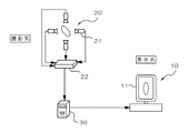
この回転ディスプレイシステムでは、図6に示すように、撮影系20において、対象物
を周囲に配置された4台の小型カメラ21によって撮影し、その撮影画像を画像合成器2
2によって合成した後に制御用PC30に送り、所定の画像処理を行う。その後、この画
像処理された合成画像を基に、複数の表示方位に応じた複数の表示画像を形成し、これら
の各表示画像を図7に示す画像表示装置10に順次送出し、支持台12上において自転軸
11Xの周りを高速に自転する表示体11の自転角度に応じてその表示面11G上に表示
画像を表示するようになっている。
In this rotating display system, as shown in FIG. 6, in an
2 and then sent to the
一方、画像投影装置及びスクリーンを高速に体積走査しながら、画像投影装置からスク
リーンに対象物の断面画像を順次投影することにより、視覚の残存効果を利用して立体画
像を表示するように構成された立体画像表示装置も知られている(例えば、以下の特許文
献1参照)。
ところで、上記の回転ディスプレイシステムにおいては表示面やスクリーンを自転させ
ながら表示を行っているが、その自転軸は表示体やスクリーンとほぼ重なった位置に設定
されていることにより、画像の中心すなわち自転軸と、観察者との間の距離が変化しない
ため、視認される画像が立体感や臨場感に乏しいものになるという問題があった。
By the way, in the above rotating display system, display is performed while rotating the display surface or the screen, but the rotation axis is set at a position almost overlapping with the display body or the screen, so that the center of the image, that is, the rotation. Since the distance between the axis and the observer does not change, there is a problem that a visually recognized image is poor in stereoscopic effect and realism.
一方、上記の画像投影装置及びスクリーンを用いた立体画像表示装置では、スクリーン
を体積走査することにより立体画像を表示するように構成したものであるが、図5に示す
画像表示装置10と同様にスクリーンを自転させた場合には、上記と同様に画像の中心、
すなわち自転軸と、観察者との距離が変化しないため、通常の画像を投影しただけでは立
体感や臨場感のある画像を視認することができない。また、対象物の断面画像をスクリー
ンの体積走査の態様(例えば回転角度)に応じて複雑に加工して投影しなければならない
ため、投影画像の処理が複雑になるという問題点がある。また、このような断面画像を投
影する方法では、視認される画像が対象物の透視画像となるので、画像の明瞭性を高める
ことが難しいという問題点がある。
On the other hand, the stereoscopic image display device using the image projection device and the screen is configured to display a stereoscopic image by volume scanning the screen, but is similar to the
In other words, since the distance between the rotation axis and the observer does not change, it is impossible to visually recognize an image having a stereoscopic effect or a sense of presence only by projecting a normal image. Moreover, since the cross-sectional image of the object must be processed and projected in a complicated manner according to the volume scanning mode (for example, the rotation angle) of the screen, there is a problem that the processing of the projected image becomes complicated. In addition, such a method of projecting a cross-sectional image has a problem that it is difficult to improve the clarity of the image because the image to be viewed is a perspective image of the object.
そこで本発明は上記問題点を解決するものであり、その目的は、従来よりも高い立体感
や臨場感を有する画像を形成することのできる画像表示装置を提供することにある。また
、他の目的は、従来よりも簡単な画像処理で足り、しかも、従来よりも明瞭な立体的画像
を表示できる画像表示装置を提供することにある。
Accordingly, the present invention solves the above-described problems, and an object of the present invention is to provide an image display apparatus capable of forming an image having a higher stereoscopic effect and realism than before. Another object of the present invention is to provide an image display device that can display a stereoscopic image that is clearer than the conventional image processing and that requires simple image processing.
本発明の画像表示装置は、画像を表示する表示面を表裏にそれぞれ有する表示体と、該
表示体を回転させる回転駆動手段とを有する画像表示装置において、前記表示体は、前記
表示体から離間した回転軸線の周りに、一方の前記表示面が前記回転軸線に対向し、他方
の前記表示面が前記回転軸線とは反対側に向いた姿勢で、回転可能に構成されていること
を特徴とする。
The image display device of the present invention is an image display device having display bodies each having a display surface for displaying an image on the front and back, and a rotation driving means for rotating the display body. The display body is separated from the display body. One of the display surfaces is opposed to the rotation axis around the rotation axis, and the other display surface is configured to be rotatable in a posture facing the opposite side of the rotation axis. To do.
この発明によれば、表示体が回転軸線の周りを回転すると、一方の表示面が回転軸線に
対向した状態で回転し、他方の表示面が回転軸線とは反対側を向いた状態で回転すること
となるので、回転軸線の周りの所定方位から表示面を観察した場合、一方の表示面が回転
軸線の背後に配置されたタイミングと、他方の表示面が回転軸線の手前に配置されたタイ
ミングとにおいてそれぞれの表示面に表示画像が形成されれば、観察者は、視線方向の前
後の異なる距離に表示された表示画像が重なることにより構成される、立体感や臨場感の
ある画像を視認できることになる。また、表裏の表示面が回転軸線及びその反対側を向い
た姿勢で回転するだけであるので、表示面上に形成すべき表示画像を形成するために複雑
な画像処理が不要であり、また、表示面に対する視線角度を大きく確保することが可能に
なるので、画像を明瞭に表示することが可能になる。
According to the present invention, when the display body rotates around the rotation axis, the display body rotates with one display surface facing the rotation axis, and the other display surface rotates with the other side facing the rotation axis. Therefore, when the display surface is observed from a predetermined orientation around the rotation axis, the timing when one display surface is arranged behind the rotation axis and the timing when the other display surface is arranged in front of the rotation axis When a display image is formed on each display surface, the observer visually recognizes an image with a three-dimensional effect or a sense of presence that is formed by overlapping display images displayed at different distances before and after the line-of-sight direction. It will be possible. Further, since the front and back display surfaces only rotate in a posture facing the rotation axis and the opposite side, complicated image processing is not necessary to form a display image to be formed on the display surface, Since it is possible to ensure a large viewing angle with respect to the display surface, it is possible to display an image clearly.
本発明において、前記表示面は、前記回転軸線を中心とする3次元回転体の外表面に沿
った湾曲面形状を有することが好ましい。これによれば、表示面が回転軸線を中心として
回転したとき、観察者から見た所定方向にある表示面の部分の視線方向の位置や面形状が
ほとんど変化しないので、観察者から見た表示画像の位置が変化しないように、表示面に
対して回転軸線周りの回転方向とは逆方向に表示画像を移動させる態様で表示を行った場
合、表示面上に画像が表示される時間を長く構成することが可能になるので、観察者の視
認する画像の明るさや明瞭性を高めることができる。また、スクリーン面として構成され
た表示面に対して画像投影装置から所定の画像を投影する場合には、予め表示面の湾曲面
形状に合致した画像投影を行うことにより、表示体が回転していく過程で表示面の投影範
囲におけるスクリーンの面方位がほとんど変化しないので、投影画像に台形歪が発生する
ことを防止できることから、観察者の視認する画像がぼけることを防止でき、また、上記
と同様に画像投影の時間を長くすることにより、画像の明るさや明瞭性を高めることがで
きる。
In the present invention, it is preferable that the display surface has a curved surface shape along the outer surface of the three-dimensional rotating body centered on the rotation axis. According to this, when the display surface rotates around the rotation axis, the position and surface shape in the line-of-sight direction of the portion of the display surface in the predetermined direction seen from the observer hardly change, so the display seen from the observer When the display image is displayed in such a manner that the display image is moved in the direction opposite to the rotation direction around the rotation axis so that the position of the image does not change, the time for displaying the image on the display surface is lengthened. Since it becomes possible to configure, the brightness and clarity of the image visually recognized by the observer can be enhanced. In addition, when a predetermined image is projected from the image projection device onto a display surface configured as a screen surface, the display body rotates by performing image projection that matches the curved surface shape of the display surface in advance. Since the screen orientation in the projection range of the display surface hardly changes in the course of the process, it is possible to prevent the trapezoidal distortion from occurring in the projected image, so that the image visually recognized by the observer can be prevented from being blurred. Similarly, by increasing the image projection time, the brightness and clarity of the image can be improved.
ここで、上記の3次元回転体とは、回転軸線を中心に所定の断面形状を回転させたとき
に、当該断面形状が通過する空間部分により構成される立体形状を言う。上記の表示面は
、上記の3次元回転体の外表面に沿った形状であれば如何なる形状であってもよいが、例
えば、前記回転軸線を中心とした円筒面、前記回転軸線上の所定位置を中心とした球面、
前記回転軸線を中心とする樽状面(トーリック面)などが挙げられる。これらの中でも、
上記表示面が回転軸線を中心とする円筒面形状を有する場合には、回転軸線を中心とする
半径方向にのみ表示面が湾曲しているため、表示面上に表示すべき表示画像を形成するた
めの画像処理も容易になり、また、表示体にその表示面を形成することが製造上容易にで
きるようになり、さらに、表示の視認性も良好であるなどという利点が得られる。
Here, the three-dimensional rotating body refers to a three-dimensional shape constituted by a space portion through which the cross-sectional shape passes when a predetermined cross-sectional shape is rotated around the rotation axis. The display surface may have any shape as long as it is along the outer surface of the three-dimensional rotating body. For example, the display surface may be a cylindrical surface centered on the rotation axis, or a predetermined position on the rotation axis. A spherical surface centered on
Examples include a barrel-shaped surface (toric surface) around the rotation axis. Among these,
When the display surface has a cylindrical surface shape centered on the rotation axis, the display surface is curved only in the radial direction centered on the rotation axis, so that a display image to be displayed on the display surface is formed. Therefore, it is possible to easily perform image processing, and to easily form the display surface on the display body in terms of manufacturing, and to obtain an advantage that display visibility is good.
本発明において、前記表示面は投影画像を表示可能なスクリーン面であり、前記表示面
に対して画像を投影する画像投影手段をさらに有することが好ましい。これによれば、表
示面をスクリーン面とすることで、表示体を簡易に構成できる。この場合、画像投影手段
は、表示体とともに回転するように構成してもよく、また、回転軸線に対して所定位置に
固定されていてもよい。さらに、画像投影手段がスクリーン面の観察者側にある構成(フ
ロント・プロジェクション方式)であってもよく、また、画像投影手段がスクリーン面の
観察者とは反対側にある構成(リア・プロジェクション方式)であってもよい。さらにま
た、画像投影手段は、前記表示体の周囲の異なる角度位置に複数設けられていてもよい。
In the present invention, it is preferable that the display surface is a screen surface capable of displaying a projected image, and further includes image projecting means for projecting the image onto the display surface. According to this, a display body can be simply comprised by making a display surface into a screen surface. In this case, the image projection means may be configured to rotate together with the display body, and may be fixed at a predetermined position with respect to the rotation axis. Further, the image projection means may be configured on the viewer side of the screen surface (front projection method), or the image projection means may be configured on the opposite side of the screen surface observer (rear projection method). ). Furthermore, a plurality of image projection means may be provided at different angular positions around the display body.
本発明において、前記画像投影手段は、前記回転軸線を中心とする画像投影領域を有す
ることが好ましい。これによれば、表示面のより広い範囲に対して画像を投影することが
でき、また、表示面に対してより長い間画像を投影することができるため、観察者の視認
する画像の面積を大きくし、或いは、画像の明るさやコントラストを高めることができる
。
In the present invention, it is preferable that the image projection means has an image projection area centered on the rotation axis. According to this, since the image can be projected on a wider range of the display surface, and the image can be projected on the display surface for a longer time, the area of the image visually recognized by the observer can be reduced. The brightness or contrast of the image can be increased.
本発明において、前記表示面には、前記回転軸線より観察者側にあるときには近景画像
が表示され、前記回転軸線の観察者とは反対側にあるときには遠景画像が表示されること
が好ましい。これによれば、観察者は、視覚の残存効果によって近景画像と遠景画像とを
重ね合わせた状態で視ることになるが、このとき、近景画像は近い場所にて表示され、遠
景画像は遠い場所にて表示されるため、立体感や臨場感のある画像を視認することができ
る。
In the present invention, it is preferable that a near-field image is displayed on the display surface when the viewer is closer to the observer than the rotation axis, and a distant image is displayed when the observer is on the opposite side of the rotation axis. According to this, the observer sees the foreground image and the distant view image superimposed due to the visual residual effect. At this time, the foreground image is displayed at a close place and the distant view image is far. Since it is displayed at a place, it is possible to visually recognize an image having a three-dimensional effect or a sense of reality.
次に、添付図面を参照して本発明に係る画像表示装置の実施形態について説明する。 Next, an embodiment of an image display device according to the present invention will be described with reference to the accompanying drawings.
[第1実施形態]
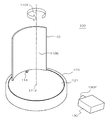
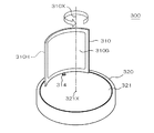
図1は本発明に係る第1実施形態の画像表示装置100の全体構成を示す概略斜視図、
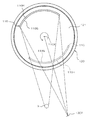
図2は、画像表示装置100の概略平面図である。この画像表示装置100は、表示体1
10と、この表示体110を支持する支持台120と、画像投影手段130とを有する。
[First embodiment]
FIG. 1 is a schematic perspective view showing the overall configuration of an
FIG. 2 is a schematic plan view of the
10, a
表示体110は板状体であり、その表裏両面に、スクリーンとして機能する表示面11
0G,110Hがそれぞれ設けられている。表示体110は支軸114を介して支持台1
20の回転板121に接続固定されている。
The
0G and 110H are provided. The
It is connected and fixed to 20
支持台120においては、回転板121が回転中心121Xを中心に回転可能に構成さ
れ、支持台120内に配置された図示しない回転駆動手段(電動モータや輪列など)によ
って回転駆動されるように構成されている。したがって、回転板121が回転すると、表
示体110は回転軸線110Xの周りを回転するようになっている。
In the
具体的には、表示体110は、断面円弧状に湾曲した板状体であり、図2に示すように
、凹状に湾曲した表示面110Gと、凸状に湾曲した表示面110Hとを有する。表示面
110Gと110Hは、回転軸線110Xを中心とした円筒面として構成されている。一
方の表示面110Gは内側に向き、回転軸線110Xに対向している。また、他方の表示
面110Hは外側に向き、回転軸線110Xとは反対側に向いている。
Specifically, the
画像投影手段130は、液晶プロジェクタや映写機などで構成される。画像投影手段1
30は適宜の画像を上記の表示面110G,110Hに画像を投影するように構成されて
いる。具体的には、この画像投影手段130は、回転軸線110Xを含む領域に画像を投
影するように構成されている。この実施形態において、画像投影手段130の画像投影部
(画像を外部へ投射する部分)130Pから投影される画像は、表示面110G,110
Hに直接投影され、観察者はその投影された画像を所定方位から視認できるように構成さ
れている。この場合、画像投影手段130の画像投影部130Pは表示面110G,11
0Hの観察者側に配置され、いわゆるフロント・プロジェクション方式によって表示面1
10G,110Hに表示画像を投影するように構成されている。
The image projecting means 130 is composed of a liquid crystal projector, a projector or the like. Image projection means 1
30 is configured to project an appropriate image onto the display surfaces 110G and 110H. Specifically, the
The image is directly projected onto H, and the observer can view the projected image from a predetermined direction. In this case, the
It is arranged on the viewer side of 0H, and the display surface 1 is formed by a so-called front projection method.
The display image is projected onto 10G and 110H.
本実施形態においては、図2に示すように、表示面110G,110Hが回転軸線11
0Xの周りを回転する方向に沿って湾曲しているので、画像投影手段130によって投影
された投影画像は、その湾曲面上に投影されたときに、たとえば観察者Xにとって正常な
(投影歪のない)画像として認識される態様で投影される。
In the present embodiment, as shown in FIG. 2, the display surfaces 110 </ b> G and 110 </ b> H have the
Since it is curved along the direction of rotation around 0X, the projected image projected by the image projecting means 130 is normal to the observer X (for example, of the projection distortion) when projected onto the curved surface. Not) is projected in a manner recognized as an image.
また、画像投影手段130は、表示体110が回転軸線110Xを中心に回転するとき
、図2に実線で示すように、表示面110Gに画像を投影するタイミングと、表示面11
0Hに画像を投影するタイミングとが生ずる。ここで、本実施形態の場合、画像投影手段
130は回転軸線110Xから見て表示体110の回転軌道の外側に配置されるので、表
示面110Gに対しては、画像投影部130Pから見て回転軸線110Xの背後に配置さ
れる時点で画像が投影され、表示面110Hに対しては、画像投影部130Pから見て回
転軸線110Xの手前に配置される時点で画像が投影される。
Further, the
The timing for projecting the image to 0H occurs. Here, in the case of the present embodiment, the image projecting means 130 is disposed outside the rotation trajectory of the
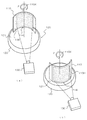
図3は、上記実施形態の画像表示装置100を動作させ、表示体110を回転させたと
きの画像表示状態を示す概略斜視図である。ここで、図3(a)は表示面110Gに画像
が投影されている状態を示し、図3(b)は表示面110Hに画像が投影されている状態
を示す。表示体110が回転軸線110Xの周りに回転するとき、画像投影手段130の
側に観察者がいるとすれば、表示面110Gは観察者に対して遠く離れた位置にて画像を
表示し、表示面110Hはそれよりも観察者に近い位置にて画像を表示することになる。
そして、観察者は表示面110G上に表示された画像と、表示面110H上に表示された
画像とを交互に繰り返し視認することになる。
FIG. 3 is a schematic perspective view showing an image display state when the
Then, the observer sees the image displayed on the
本実施形態の画像表示装置100においては、表示体110が回転することによって観
察者の視線方向の前後に配置される表示面110Gと110Hによって画像が交互に表示
されることから、例えば、表示面110G上に遠景画像を表示させ、表示面110H上に
近景画像を表示させることにより、観察者は、視覚の残存効果によって両画像が重ねあわ
された状態の画像を視認することになる。これによって、観察者は立体感や臨場感のある
画像を視認できることになる。
In the
また、本実施形態においては、表示面110Gと110Hが回転軸線110Xを中心と
する円筒面であることにより、図3(a)及び(b)に示すように、表示体110が図示
一点鎖線で示す角度位置から図示実線で示す角度位置に回転する期間においては、画像投
影手段130から投影される表示面上の投影画面の面形状が変化せず、その結果、上記期
間内においては同一の画像を投影し続けても台形歪が生ずることはない。したがって、表
示面110G,110Hに対して画像を投影し続ける時間を長くしても観察者の視認する
画像が劣化することはないので、従来に比べて画像の投影時間を長くすることができるこ
とから、より明るく、コントラストの高い画像を形成し得るようになる。
Further, in the present embodiment, the display surfaces 110G and 110H are cylindrical surfaces having the
なお、画像表示装置100においては、表示体110の周囲に画像投影手段130が1
つだけ配置されているが、回転軸線110Xの周りの異なる角度位置に複数の画像投影手
段を配置してもよい。この場合には、それぞれの画像投影手段によって投影された画像を
異なる角度位置においてそれぞれ視認できるようになる。
In the
However, a plurality of image projection means may be arranged at different angular positions around the
また、このように複数の画像投影手段を配置する場合においては、異なる画像投影手段
によってそれぞれ投影される画像が重なり合って視認されてしまうといったことを防止す
るために、表示面110G,110H上に形成される表示画像の視認角度を制限すること
が好ましい。例えば、表示面110G,110H上に視認角度を制限するための光学フィ
ルタを配置したり、或いは、表示面110G,110Hを再帰反射性スクリーンによって
構成したりすることができる。再帰反射性スクリーンは、例えば、多数の透明な微細な球
体や円柱体などを反射素材の表面に埋設したものなどが挙げられる。
Further, when a plurality of image projecting units are arranged in this way, the images projected by the different image projecting units are formed on the display surfaces 110G and 110H in order to prevent the images projected from each other from being overlapped and viewed. It is preferable to limit the viewing angle of the displayed image. For example, an optical filter for limiting the viewing angle may be disposed on the display surfaces 110G and 110H, or the display surfaces 110G and 110H may be configured by a retroreflective screen. Examples of the retroreflective screen include those in which a large number of transparent fine spheres and cylinders are embedded in the surface of a reflective material.
[第2実施形態]
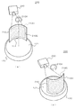
次に、図4を参照して、本発明に係る第2実施形態の画像表示装置200について説明
する。図4(a)及び(b)は第2実施形態の画像表示装置200の動作状態を示す概略
斜視図である。この実施形態において、第1実施形態と同一部分については同一符号を付
して、その説明は省略する。この画像表示装置200には、上記第1実施形態の表示体1
10の代わりに、背面に投影された画像を表面上に表示できるスクリーン構造を有する表
示体210が設けられている。この表示体210は、表示面210Gに画像を投影すると
、その投影画像が表示面210H上に表示され、表示面210Hに画像を投影すると、そ
の投影画像が表示面210G上に表示されるようになっている。なお、表示体210及び
その表示面210G,210Hは、上記第1実施形態の表示体110及び表示面210G
、210Hと同様の形状を備えている。
[Second Embodiment]
Next, an
Instead of 10, a
, 210H has the same shape as 210H.
本実施形態では、表示面210G,210Hに対して画像投影手段230とは反対側か
ら投影画像を視認できるように構成され、いわゆるリア・プロジェクション方式(背面投
射方式)の画像表示装置となっている。このような表示体210としては、例えば、公知
のレンチキュラーレンズスクリーンと拡散フィルタを組み合わせたものなどを用いること
ができる。
In the present embodiment, the projected image can be viewed from the opposite side of the
この第2実施形態においては、表示体210に対して画像投影手段230とは反対側に
いる観察者に画像を視認させることができる。この実施形態でも、第1実施形態と同様に
、図4(a)に示す表示面210G上に表示された画像と、図4(b)に示す表示面21
0H上に表示された画像とを重ね合わせた合成画像が形成される。この場合、作用効果は
第1実施形態と全く同様である。また、この実施形態では、観察者側に画像投影手段23
0を配置する必要がないので、画像投影手段230が観察者の邪魔にならないとともに、
観察者が投影している画像に干渉して投影画像に影ができるなどといったことも回避でき
る。
In the second embodiment, an image can be visually recognized by an observer on the opposite side of the
A composite image is formed by superimposing the image displayed on 0H. In this case, the effect is exactly the same as in the first embodiment. In this embodiment, the image projection means 23 is provided on the observer side.
Since it is not necessary to place 0, the image projection means 230 does not disturb the observer,
It can also be avoided that the projected image is shaded by interference with the image projected by the observer.
なお、この第2実施形態においても、表示体210の周囲の異なる角度位置に複数の画
像投影手段を配置することができる。また、隣接する画像が重なり合って視認されてしま
うことを防止するために、上記第1実施形態と同様に表示体210の視認角度を狭めるこ
とが好ましい。
In the second embodiment, a plurality of image projecting units can be arranged at different angular positions around the
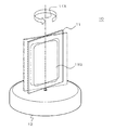
[第3実施形態]
次に、図5を参照して本発明に係る第3実施形態について説明する。この実施形態では
、表示体310、表示面310G,310H、支持台320及び回転板321は基本的に
上記各実施形態と同様の機能を有するが、表示体310に設けられる表示面310G,3
10Hが投影スクリーンではなく、それ自体で表示画像を形成可能な表示装置によって構
成される表示画面となっている点で上記実施形態とは異なる。この場合、表示体310の
内部には電気光学表示装置が内蔵され、表示面310G,310Hにそれぞれ独立した画
像を表示できるように構成されている。このような表示体310の具体的構造としては2
つの電気光学表示装置を背中合わせに配置した構造などが挙げられる。
[Third Embodiment]
Next, a third embodiment according to the present invention will be described with reference to FIG. In this embodiment, the
10H is different from the above-described embodiment in that 10H is not a projection screen but a display screen constituted by a display device that can form a display image by itself. In this case, an electro-optic display device is built in the
For example, a structure in which two electro-optic display devices are arranged back to back.
上記の電気光学表示装置は薄型ディスプレイが望ましい。具体的には、液晶表示装置(
LCD:Liquid Crystal Display)、プラズマディスプレイ表示装置(PDP:Plasma D
isplay Panel)、エレクトロルミネッセンス表示装置(Electroluminescence)、有機エ
レクトロルミネッセンス表示装置(Organic Electroluminescence)、電気泳動ディスプ
レイ表示装置、電子放出素子を用いた表示装置(Field Emission Display 及び Surface-
Conduction Electron-Emitter Display等)などの各種の表示装置を用いることができる
。
The electro-optic display device is preferably a thin display. Specifically, liquid crystal display devices (
LCD: Liquid Crystal Display), Plasma display device (PDP: Plasma D)
isplay Panel), electroluminescence display device (Electroluminescence), organic electroluminescence display device (Organic Electroluminescence), electrophoretic display display device, display device using electron emission elements (Field Emission Display and Surface-
Various display devices such as Conduction Electron-Emitter Display can be used.
この実施形態でも、表示体310の表示面310G,310Hにそれぞれ画像を表示す
ることで、上記各実施形態と同様の重ね合わせられた複合画像を形成することができ、立
体感や臨場感を高めることができる。また、この実施形態では、表示体310のみで表示
画像を形成できるので、画像投影装置が不要になり、コンパクトに構成できる。さらに、
図示例とは異なり、表示体310の表示面310G,310Hが平面状に構成された場合
でも、画像投影を用いていないので、台形歪は発生しない。
Also in this embodiment, by displaying the images on the display surfaces 310G and 310H of the
Unlike the example shown in the figure, even when the display surfaces 310G and 310H of the
尚、本発明に係る画像表示装置は、上述の図示例にのみ限定されるものではなく、本発
明の要旨を逸脱しない範囲内において種々変更を加え得ることは勿論である。例えば、上
記実施形態においては、表示体に設けられる表示面は、それぞれ回転軸線を中心とした円
筒面状に構成されているが、円筒面以外であっても、所定の断面形状を回転軸線の周りに
回転させてなる3次元回転体の外表面に沿った湾曲面形状とすることができる。例えば、
回転軸線を中心とした球の表面の一部分や樽状体の側面の一部分(トーリック面)などの
各種の湾曲面形状とすることができる。
Note that the image display device according to the present invention is not limited to the illustrated examples described above, and it is needless to say that various modifications can be made without departing from the gist of the present invention. For example, in the above-described embodiment, the display surface provided on the display body is configured in a cylindrical surface shape with the rotation axis as the center, but a predetermined cross-sectional shape of the rotation axis is not limited to the cylindrical surface. It can be set as the curved surface shape along the outer surface of the three-dimensional rotating body rotated around. For example,
Various curved surface shapes such as a part of the surface of the sphere around the rotation axis and a part of the side surface of the barrel (toric surface) can be used.
また、本発明に係る表示面は、上記の3次元回転体の外表面に沿った湾曲形状に限らず
、平坦面であってもよい。この場合に、第1実施形態や第2実施形態のように投影画像手
段によって画像を表示面上に投影すると、台形歪が生ずることが考えられるが、画像投影
時間を短くしたり、或いは、時間とともに表示面の角度が投影方向に対して傾斜するのに
合わせて、画像の投影態様を変化させたりすることによって、台形歪の発生を抑制し、支
障なく画像を視認できるように構成できる。
The display surface according to the present invention is not limited to the curved shape along the outer surface of the three-dimensional rotating body, and may be a flat surface. In this case, when the image is projected onto the display surface by the projection image means as in the first embodiment or the second embodiment, it is considered that trapezoidal distortion occurs. However, the image projection time can be shortened or the time can be reduced. At the same time, by changing the projection mode of the image in accordance with the inclination of the display surface with respect to the projection direction, it is possible to suppress the occurrence of trapezoidal distortion so that the image can be viewed without hindrance.
100、200、300…画像表示装置、110…表示体、110G,110H…表示面
、120…画像投影手段、110X…回転軸線、114…支軸、120…支持台、121
…回転板
DESCRIPTION OF
... Rotating plate
Claims (6)
動手段とを有する画像表示装置において、
前記表示体は、前記表示体から離間した回転軸線の周りに、一方の前記表示面が前記回
転軸線に対向し、他方の前記表示面が前記回転軸線とは反対側に向いた姿勢で、回転可能
に構成されていることを特徴とする画像表示装置。 In an image display device having display bodies each having a display surface for displaying an image on the front and back sides, and rotation driving means for rotating the display bodies,
The display body is rotated around a rotation axis that is separated from the display body, with one display surface facing the rotation axis and the other display surface facing away from the rotation axis. An image display device characterized by being configured.
有することを特徴とする請求項1に記載の画像表示装置。 The image display device according to claim 1, wherein the display surface has a curved surface shape along an outer surface of a three-dimensional rotating body centered on the rotation axis.
2に記載の画像表示装置。 The image display device according to claim 2, wherein the display surface has a cylindrical surface shape centered on the rotation axis.
影する画像投影手段をさらに有することを特徴とする請求項1に記載の画像表示装置。 The image display apparatus according to claim 1, wherein the display surface is a screen surface capable of displaying a projection image, and further includes image projection means for projecting an image onto the display surface.
る請求項4に記載の画像表示装置。 The image display device according to claim 4, wherein the image projection unit has an image projection region centered on the rotation axis.
回転軸線の観察者とは反対側にあるときには遠景画像が表示されることを特徴とする請求
項1乃至5のいずれか一項に記載の画像表示装置。
The near-field image is displayed on the display surface when the viewer is closer to the observer than the rotation axis, and the distant image is displayed when the observer is on the opposite side of the rotation axis. The image display device according to claim 5.
Priority Applications (1)
| Application Number | Priority Date | Filing Date | Title |
|---|---|---|---|
| JP2004109216A JP2005295325A (en) | 2004-04-01 | 2004-04-01 | Image display device |
Applications Claiming Priority (1)
| Application Number | Priority Date | Filing Date | Title |
|---|---|---|---|
| JP2004109216A JP2005295325A (en) | 2004-04-01 | 2004-04-01 | Image display device |
Publications (1)
| Publication Number | Publication Date |
|---|---|
| JP2005295325A true JP2005295325A (en) | 2005-10-20 |
Family
ID=35327750
Family Applications (1)
| Application Number | Title | Priority Date | Filing Date |
|---|---|---|---|
| JP2004109216A Withdrawn JP2005295325A (en) | 2004-04-01 | 2004-04-01 | Image display device |
Country Status (1)
| Country | Link |
|---|---|
| JP (1) | JP2005295325A (en) |
Cited By (6)
| Publication number | Priority date | Publication date | Assignee | Title |
|---|---|---|---|---|
| JP2009244728A (en) * | 2008-03-31 | 2009-10-22 | Casio Comput Co Ltd | Display |
| JP2010020210A (en) * | 2008-07-14 | 2010-01-28 | Seiko Epson Corp | Manufacturing method and manufacture device of screen, and screen |
| WO2011049025A1 (en) * | 2009-10-20 | 2011-04-28 | シャープ株式会社 | Three dimensional video display device |
| JP5616549B1 (en) * | 2013-08-22 | 2014-10-29 | 敏之 仁木 | Curved mirror image display |
| US9151957B2 (en) | 2012-02-07 | 2015-10-06 | Samsung Display Co., Ltd. | Three-dimensional image display device |
| JP2023539035A (en) * | 2020-08-07 | 2023-09-13 | ▲億▼信科技▲発▼展有限公司 | Unidirectional uniform light beam expansion screen and three-dimensional display device |
-
2004
- 2004-04-01 JP JP2004109216A patent/JP2005295325A/en not_active Withdrawn
Cited By (9)
| Publication number | Priority date | Publication date | Assignee | Title |
|---|---|---|---|---|
| JP2009244728A (en) * | 2008-03-31 | 2009-10-22 | Casio Comput Co Ltd | Display |
| JP2010020210A (en) * | 2008-07-14 | 2010-01-28 | Seiko Epson Corp | Manufacturing method and manufacture device of screen, and screen |
| WO2011049025A1 (en) * | 2009-10-20 | 2011-04-28 | シャープ株式会社 | Three dimensional video display device |
| US9047793B2 (en) | 2009-10-20 | 2015-06-02 | Sharp Kabushiki Kaisha | Three dimensional video display device |
| US9151957B2 (en) | 2012-02-07 | 2015-10-06 | Samsung Display Co., Ltd. | Three-dimensional image display device |
| JP5616549B1 (en) * | 2013-08-22 | 2014-10-29 | 敏之 仁木 | Curved mirror image display |
| JP2015091634A (en) * | 2013-08-22 | 2015-05-14 | 敏之 仁木 | Curved mirror-type image display |
| JP2023539035A (en) * | 2020-08-07 | 2023-09-13 | ▲億▼信科技▲発▼展有限公司 | Unidirectional uniform light beam expansion screen and three-dimensional display device |
| JP7511295B2 (en) | 2020-08-07 | 2024-07-05 | ▲億▼信科技▲発▼展有限公司 | One-way uniform light beam expanding screen and three-dimensional display device |
Similar Documents
| Publication | Publication Date | Title |
|---|---|---|
| US9047793B2 (en) | Three dimensional video display device | |
| JP4267668B2 (en) | 3D image display device | |
| JP3955589B2 (en) | 3D display device | |
| JP4576131B2 (en) | Stereoscopic two-dimensional image display apparatus and stereoscopic two-dimensional image display method | |
| JP2003524927A (en) | System and method for generating and displaying panoramic images and videos | |
| JP3927578B2 (en) | Display device | |
| JP2015232633A (en) | Display device | |
| JP2005295325A (en) | Image display device | |
| JP2005221946A (en) | Driving method of rotary display device | |
| JP4482556B2 (en) | Stereoscopic two-dimensional image display device | |
| JP2004045694A (en) | Stereoscopic image display apparatus and method | |
| WO2012063789A1 (en) | Display device, method for controlling display device, program and recording medium | |
| JPH10336706A (en) | Stereoscopic display device | |
| KR20030080763A (en) | 3d display system | |
| JP2007101929A (en) | Projection type 3D display device | |
| JP4867854B2 (en) | Virtual image display device | |
| JP4649297B2 (en) | 3D image display method and 3D image display apparatus | |
| WO2023000544A1 (en) | Three-dimensional display system | |
| JP4568643B2 (en) | 3D image display device | |
| JP2006085135A (en) | 3D display device | |
| JP6719240B2 (en) | Image projection apparatus and planetarium apparatus using the same | |
| JP2005295324A (en) | Image display device | |
| JP2005202126A (en) | Rotary display device and driving method of rotary display device | |
| CN118642276A (en) | Real 3D holographic image equipment | |
| WO2009091366A1 (en) | Display system |
Legal Events
| Date | Code | Title | Description |
|---|---|---|---|
| A300 | Withdrawal of application because of no request for examination |
Free format text: JAPANESE INTERMEDIATE CODE: A300 Effective date: 20070605 |