JP5205281B2 - Catalytic etching of carbon fiber - Google Patents
Catalytic etching of carbon fiber Download PDFInfo
- Publication number
- JP5205281B2 JP5205281B2 JP2008554757A JP2008554757A JP5205281B2 JP 5205281 B2 JP5205281 B2 JP 5205281B2 JP 2008554757 A JP2008554757 A JP 2008554757A JP 2008554757 A JP2008554757 A JP 2008554757A JP 5205281 B2 JP5205281 B2 JP 5205281B2
- Authority
- JP
- Japan
- Prior art keywords
- etching
- carbon
- nanofibers
- iron
- carbon fiber
- Prior art date
- Legal status (The legal status is an assumption and is not a legal conclusion. Google has not performed a legal analysis and makes no representation as to the accuracy of the status listed.)
- Expired - Fee Related
Links
Images


Classifications
-
- D—TEXTILES; PAPER
- D06—TREATMENT OF TEXTILES OR THE LIKE; LAUNDERING; FLEXIBLE MATERIALS NOT OTHERWISE PROVIDED FOR
- D06M—TREATMENT, NOT PROVIDED FOR ELSEWHERE IN CLASS D06, OF FIBRES, THREADS, YARNS, FABRICS, FEATHERS OR FIBROUS GOODS MADE FROM SUCH MATERIALS
- D06M11/00—Treating fibres, threads, yarns, fabrics or fibrous goods made from such materials, with inorganic substances or complexes thereof; Such treatment combined with mechanical treatment, e.g. mercerising
- D06M11/01—Treating fibres, threads, yarns, fabrics or fibrous goods made from such materials, with inorganic substances or complexes thereof; Such treatment combined with mechanical treatment, e.g. mercerising with hydrogen, water or heavy water; with hydrides of metals or complexes thereof; with boranes, diboranes, silanes, disilanes, phosphines, diphosphines, stibines, distibines, arsines, or diarsines or complexes thereof
- D06M11/05—Treating fibres, threads, yarns, fabrics or fibrous goods made from such materials, with inorganic substances or complexes thereof; Such treatment combined with mechanical treatment, e.g. mercerising with hydrogen, water or heavy water; with hydrides of metals or complexes thereof; with boranes, diboranes, silanes, disilanes, phosphines, diphosphines, stibines, distibines, arsines, or diarsines or complexes thereof with water, e.g. steam; with heavy water
-
- D—TEXTILES; PAPER
- D01—NATURAL OR MAN-MADE THREADS OR FIBRES; SPINNING
- D01F—CHEMICAL FEATURES IN THE MANUFACTURE OF ARTIFICIAL FILAMENTS, THREADS, FIBRES, BRISTLES OR RIBBONS; APPARATUS SPECIALLY ADAPTED FOR THE MANUFACTURE OF CARBON FILAMENTS
- D01F11/00—Chemical after-treatment of artificial filaments or the like during manufacture
- D01F11/10—Chemical after-treatment of artificial filaments or the like during manufacture of carbon
- D01F11/16—Chemical after-treatment of artificial filaments or the like during manufacture of carbon by physicochemical methods
-
- D—TEXTILES; PAPER
- D06—TREATMENT OF TEXTILES OR THE LIKE; LAUNDERING; FLEXIBLE MATERIALS NOT OTHERWISE PROVIDED FOR
- D06M—TREATMENT, NOT PROVIDED FOR ELSEWHERE IN CLASS D06, OF FIBRES, THREADS, YARNS, FABRICS, FEATHERS OR FIBROUS GOODS MADE FROM SUCH MATERIALS
- D06M10/00—Physical treatment of fibres, threads, yarns, fabrics, or fibrous goods made from such materials, e.g. ultrasonic, corona discharge, irradiation, electric currents, or magnetic fields; Physical treatment combined with treatment with chemical compounds or elements
- D06M10/04—Physical treatment combined with treatment with chemical compounds or elements
- D06M10/06—Inorganic compounds or elements
-
- D—TEXTILES; PAPER
- D06—TREATMENT OF TEXTILES OR THE LIKE; LAUNDERING; FLEXIBLE MATERIALS NOT OTHERWISE PROVIDED FOR
- D06M—TREATMENT, NOT PROVIDED FOR ELSEWHERE IN CLASS D06, OF FIBRES, THREADS, YARNS, FABRICS, FEATHERS OR FIBROUS GOODS MADE FROM SUCH MATERIALS
- D06M11/00—Treating fibres, threads, yarns, fabrics or fibrous goods made from such materials, with inorganic substances or complexes thereof; Such treatment combined with mechanical treatment, e.g. mercerising
- D06M11/32—Treating fibres, threads, yarns, fabrics or fibrous goods made from such materials, with inorganic substances or complexes thereof; Such treatment combined with mechanical treatment, e.g. mercerising with oxygen, ozone, ozonides, oxides, hydroxides or percompounds; Salts derived from anions with an amphoteric element-oxygen bond
- D06M11/34—Treating fibres, threads, yarns, fabrics or fibrous goods made from such materials, with inorganic substances or complexes thereof; Such treatment combined with mechanical treatment, e.g. mercerising with oxygen, ozone, ozonides, oxides, hydroxides or percompounds; Salts derived from anions with an amphoteric element-oxygen bond with oxygen, ozone or ozonides
-
- B—PERFORMING OPERATIONS; TRANSPORTING
- B82—NANOTECHNOLOGY
- B82Y—SPECIFIC USES OR APPLICATIONS OF NANOSTRUCTURES; MEASUREMENT OR ANALYSIS OF NANOSTRUCTURES; MANUFACTURE OR TREATMENT OF NANOSTRUCTURES
- B82Y40/00—Manufacture or treatment of nanostructures
-
- D—TEXTILES; PAPER
- D06—TREATMENT OF TEXTILES OR THE LIKE; LAUNDERING; FLEXIBLE MATERIALS NOT OTHERWISE PROVIDED FOR
- D06M—TREATMENT, NOT PROVIDED FOR ELSEWHERE IN CLASS D06, OF FIBRES, THREADS, YARNS, FABRICS, FEATHERS OR FIBROUS GOODS MADE FROM SUCH MATERIALS
- D06M2101/00—Chemical constitution of the fibres, threads, yarns, fabrics or fibrous goods made from such materials, to be treated
- D06M2101/40—Fibres of carbon
Abstract
Description
本発明は、炭素繊維、特にカーボンナノファイバーをエッチングするための方法、並びに、この方法により得ることができるカーボンナノファイバーおよびそれらの使用に関する。 The present invention relates to a method for etching carbon fibers, in particular carbon nanofibers, as well as to carbon nanofibers obtainable by this method and their use.
炭素繊維、例えばカーボンナノファイバーは、多くの可能性のある用途、例えば伝導性および非常に強い複合体、エネルギー貯蔵体およびコンバーター、センサー、電界放出ディスプレーおよび放射線源、並びにナノサイズ半導体素子および試験点のための有望な材料である(Baughman, R.H.ら、Science 297:787-792 (2002))。別の有望な用途は、カーボンナノファイバーを、触媒として、または不均一触媒用支持体として(de Jong, K.P.およびGeus, J.W.、Catal. Rev.-Sci. Eng. 42:481-510 (2000))、または触媒合成用のナノサイズ反応器として(Nhut, J.M.ら、Appl. Catal. A. 254:345-363 (2003))、使用する触媒反応である。上記用途のために、その表面を化学的または物理的に変性することがしばしば必要になる。例えば、ポリマーマトリックス中のナノファイバーの完全分散および繊維とマトリックスとの間の得られる強い相互作用は、複合体における利点である(Calvert, P.、Nature 399:210-21 (1999))。触媒支持体として使用する場合、外来の原子をナノファイバー上に堆積させなければならない。アンカーポイント、例えば官能基または欠陥が、この目的のために必要になる。これを達成するため、未処理(「as-grown」)ナノファイバーの不活性表面を、変性しなければならない(Xia, W.ら、Chem. Mater. 17:5737-5742 (2005))。センサー分野における使用のために、ナノファイバーに/上に、化学基を結合させること、または特異的認識中心を有するタンパク質を固体化することが必要である。これは、通常、表面官能基または表面欠陥を製造することにより実現される(Dai, H.、Acc. Chem. Res. 35:1035-5742 (2002))。 Carbon fibers, such as carbon nanofibers, are used in many potential applications, such as conductive and very strong composites, energy storage and converters, sensors, field emission displays and radiation sources, and nano-sized semiconductor devices and test points. (Baughman, RH et al., Science 297: 787-792 (2002)). Another promising application is to use carbon nanofibers as catalysts or as supports for heterogeneous catalysts (de Jong, KP and Geus, JW, Catal. Rev.-Sci. Eng. 42: 481-510 (2000) ) Or as a nano-sized reactor for catalyst synthesis (Nhut, JM et al., Appl. Catal. A. 254: 345-363 (2003)). For these applications, it is often necessary to chemically or physically modify the surface. For example, complete dispersion of the nanofibers in the polymer matrix and the strong interaction obtained between the fibers and the matrix are advantages in the composite (Calvert, P., Nature 399: 210-21 (1999)). When used as a catalyst support, foreign atoms must be deposited on the nanofibers. Anchor points, such as functional groups or defects, are needed for this purpose. To accomplish this, the inert surface of the untreated (“as-grown”) nanofibers must be modified (Xia, W. et al., Chem. Mater. 17: 5737-5742 (2005)). For use in the sensor field, it is necessary to attach chemical groups to / on nanofibers or to solidify proteins with specific recognition centers. This is usually achieved by producing surface functional groups or surface defects (Dai, H., Acc. Chem. Res. 35: 1035-5742 (2002)).
有望な可能性のある用途によって動機付けられ、この10年の間に、カーボンナノファイバーの表面変性および官能化に関する多くの研究が行われてきている。これらの全ての方法の中でも、最も徹底的な研究は、強酸化剤、例えば硝酸、酸素プラズマ、超臨界流体、オゾンなどに通常基づく共有結合表面官能化、および例えば、その後の側鎖延長に関して行われてきた(Banerjee, S.ら、Adv. Mater. 17:17-29 (2005))。これらの酸化法は、通常、表面の酸素含量を高め、これとともに、目に見える物理的変性も、適切なパラメータの選択によって達成することができる。これらの物理的変化は、未知の位置における予測不可能な構造を有する二次元または三次元表面欠陥に限定される。極端な条件、例えば濃硫酸と濃硝酸との混合物のもと、ナノファイバーは、より小さい繊維単位に分割される(Liu, J.ら、Science 280:1253-1256 (1998))。表面欠陥の同定は、カーボンナノファイバーの小さな寸法および曲面のために難問のままである(Ishigami, M.ら、Phys. Rev. Lett. 93:196803/4 (2001))。ここで、走査トンネル顕微鏡(STM)は、非常に有効なツールである(Osvaeth, Z.ら、Phys. Rev. B. 72:045429/1-045429/6 (2005))。Fanおよびその共同研究者らは、H2Seを用いる欠陥感受性酸化を使用して、原子間力顕微鏡(AFM)によって化学的表面欠陥を同定している(Fan, Y.ら、Adv. Mater. 14:130-133 (2002))。Xia, W.ら、Chem. Mater. 17:5737-5742 (2005)において、カーボンナノファイバーの表面の変性は、鉄担持(laden)カーボンナノファイバー上へのシクロヘキサンの堆積によって行われている。しかしながら、これらの二次カーボンナノファイバー(幹および枝から構成される樹状構造)は、官能化されず、および得られる表面変性は、官能性分子を担持させる(loading)ために使用することができない。 Motivated by promising potential applications, much research on surface modification and functionalization of carbon nanofibers has been conducted over the last decade. Of all these methods, the most thorough research has been done on covalent surface functionalization usually based on strong oxidants such as nitric acid, oxygen plasma, supercritical fluids, ozone, etc., and subsequent side chain extension, for example. (Banerjee, S. et al., Adv. Mater. 17: 17-29 (2005)). These oxidation methods usually increase the oxygen content of the surface and, at the same time, visible physical modification can be achieved by selection of appropriate parameters. These physical changes are limited to 2D or 3D surface defects having unpredictable structures at unknown locations. Under extreme conditions, such as a mixture of concentrated sulfuric acid and concentrated nitric acid, nanofibers are divided into smaller fiber units (Liu, J. et al., Science 280: 1253-1256 (1998)). The identification of surface defects remains a challenge due to the small size and curvature of carbon nanofibers (Ishigami, M. et al., Phys. Rev. Lett. 93: 196803/4 (2001)). Here, the scanning tunneling microscope (STM) is a very effective tool (Osvaeth, Z. et al., Phys. Rev. B. 72: 045429 / 1-045429 / 6 (2005)). Fan and colleagues have identified chemical surface defects by atomic force microscopy (AFM) using defect-sensitive oxidation with H 2 Se (Fan, Y. et al., Adv. Mater. 14: 130-133 (2002)). In Xia, W., et al., Chem. Mater. 17: 5737-5742 (2005), the modification of the surface of carbon nanofibers is carried out by the deposition of cyclohexane onto iron-laden carbon nanofibers. However, these secondary carbon nanofibers (dendritic structures composed of trunks and branches) are not functionalized and the resulting surface modification can be used to load functional molecules. Can not.
上記問題は、現代的な高性能複合体における連続繊維として用いられる、カーボンマイクロファイバー、例えば、ポリアクリロニトリル(PAN)から製造され、およびミリメーターの範囲までの繊維束から構成される炭素繊維に対しても同様に適用される。 The above problem is for carbon fibers made from carbon microfibers, such as polyacrylonitrile (PAN), used as continuous fibers in modern high performance composites and composed of fiber bundles up to the millimeter range. The same applies.
炭素繊維、例えばカーボンナノファイバーの表面を変性するための数多くの努力に関わらず、表面官能基または表面欠陥は、現在まで、上記方法のいずれかによって、標的様式で導入することはできなかった。 Despite numerous efforts to modify the surface of carbon fibers, such as carbon nanofibers, surface functional groups or surface defects have not been able to be introduced in a targeted manner by any of the above methods to date.
驚くべきことに、この局所的エッチング技術によって、表面欠陥を、炭素繊維、例えば多壁カーボンナノファイバー(多壁カーボンナノチューブとして既知、以下、略して「MWNT」または「ナノファイバー」と称する。)上の所定の場所に製造することができる。この場合、エッチングは、水蒸気によるカーボンのガス化に基づく。 Surprisingly, this local etching technique allows surface defects to be formed on carbon fibers such as multi-walled carbon nanofibers (known as multi-walled carbon nanotubes, hereinafter referred to as “MWNT” or “nanofiber” for short). It can be manufactured in a predetermined place. In this case, the etching is based on gasification of carbon with water vapor.
![]()
![]()
ここで、ナノファイバー上に存在するナノサイズ鉄粒子は、ガス化を触媒する。エッチングは、界面で起こり、および鉄粒子が存在する炭素繊維上の場所に限定される。エッチングは、予備処理(鉄の担持、加熱時間、など)のためのパラメータおよび方法パラメータ(反応時間、温度、水の分圧、など)の適切な選択によって容易に制御することができる。このように、球状のエッチングピットを有する炭素繊維を、安価な原料(水および鉄)を使用して、環境に優しい方法で合成することができる。
また、該方法は、水素および一酸化炭素を製造する。これらは、合成ガスの主構成成分である。したがって、本発明は、以下のものを提供する。
(1)炭素繊維表面をエッチングするための方法であって、
(a)酸化による炭素繊維表面の官能化工程と、
(b)官能化表面上への金属粒子の堆積工程と、
(c)水蒸気を用いる処理による表面のエッチング工程と、
(d)酸処理による金属粒子の除去工程と
を含む、方法。
(2)上記(1)に記載の方法により得ることができる、エッチングされた炭素繊維。
(3)複合体、エネルギー貯蔵体における、センサーとしての、吸着材としての、不均一触媒用支持体としての、およびさらなる酸素官能化後の触媒活性材料としての、上記(2)に記載のエッチングされた炭素繊維の使用。
Here, the nanosize iron particles present on the nanofibers catalyze gasification. Etching occurs at the interface and is limited to locations on the carbon fibers where iron particles are present. Etching can be easily controlled by appropriate selection of parameters for pretreatment (iron loading, heating time, etc.) and method parameters (reaction time, temperature, partial pressure of water, etc.). Thus, carbon fibers having spherical etching pits can be synthesized in an environmentally friendly manner using inexpensive raw materials (water and iron).
The method also produces hydrogen and carbon monoxide. These are the main constituents of synthesis gas. Accordingly, the present invention provides the following.
(1) A method for etching a carbon fiber surface,
(a) a functionalization process of the carbon fiber surface by oxidation;
(b) a process of depositing metal particles on the functionalized surface;
(c) a surface etching step by treatment with water vapor;
(d) a step of removing metal particles by acid treatment.
(2) An etched carbon fiber obtainable by the method described in (1) above.
(3) Etching according to (2) above as a composite, energy storage, as sensor, as adsorbent, as support for heterogeneous catalysts, and as a catalytically active material after further oxygen functionalization Carbon fiber use.
本発明の炭素繊維は、カーボンナノファイバーおよびカーボンマイクロファイバーを包含するが、これらに限定されない。 The carbon fibers of the present invention include, but are not limited to, carbon nanofibers and carbon microfibers.
本発明の炭素繊維は、不飽和炭化水素化合物の重合により得ることができる構造物である。
方法(1)の第一の好ましい実施態様において、炭素繊維は、カーボンナノファイバーである。これらは、炭素を含んでなり、および例えば、触媒的熱分解によって、炭化水素から製造することができ、並びに、例えばApplied Sciences Inc.(Cedarville、オハイオ、米国)またはBayer MaterialScienceから入手可能である。
このようなカーボンナノファイバーは、通常、50〜500 nm、好ましくは約100 nmの外径、10〜100 nm、好ましくは約50 nmの内径、および10〜60 m2/g、好ましくは20〜40 m2/gの表面積を有する。本発明のエッチング方法の結果として、カーボンナノファイバーの比表面積は、90〜100 m2/gに増大する。
The carbon fiber of the present invention is a structure that can be obtained by polymerization of an unsaturated hydrocarbon compound.
In a first preferred embodiment of method (1), the carbon fiber is a carbon nanofiber. These comprise carbon and can be produced from hydrocarbons, for example, by catalytic pyrolysis, and are available, for example, from Applied Sciences Inc. (Cedarville, Ohio, USA) or Bayer MaterialScience.
Such carbon nanofibers usually have an outer diameter of 50 to 500 nm, preferably about 100 nm, an inner diameter of 10 to 100 nm, preferably about 50 nm, and 10 to 60 m 2 / g, preferably 20 to It has a surface area of 40 m 2 / g. As a result of the etching method of the present invention, the specific surface area of the carbon nanofibers is increased to 90-100 m 2 / g.
方法(1)の第二の好ましい実施態様において、炭素繊維は、マイクロファイバーである。このようなマイクロファイバーは、例えば、炭素を含んでなり、および、例えばポリアクリロニトリルファイバーの熱分解によって製造され、および例えば、Zoltek Companies Inc.(セントルイス、米国)またはToho Tenax Europe GmbHから得ることもできる。これらのマイクロファイバーは、3〜10 μm、好ましくは約6 μmの外径、および1 m2/g未満の表面積を有する。本発明のエッチング方法の結果として、マイクロファイバーの比表面積は、5〜50 m2/gに増大する。 In a second preferred embodiment of method (1), the carbon fiber is a microfiber. Such microfibers comprise, for example, carbon and are produced, for example, by pyrolysis of polyacrylonitrile fibers and can also be obtained, for example, from Zoltek Companies Inc. (St. Louis, USA) or Toho Tenax Europe GmbH . These microfibers have an outer diameter of 3-10 μm, preferably about 6 μm, and a surface area of less than 1 m 2 / g. As a result of the etching method of the present invention, the specific surface area of the microfiber increases to 5-50 m 2 / g.
本発明の方法の工程(a)において、炭素繊維の表面は、繊維の酸化処理により官能化される。これは、好ましくは、酸化性酸とともに加熱することによって、または酸素プラズマ処理によって、直ちに行うことができる。特に好ましくは、硝酸とともに加熱すること、例えば濃硝酸とともに加熱することが挙げられる。 In step (a) of the method of the present invention, the surface of the carbon fiber is functionalized by oxidizing the fiber. This can be done immediately, preferably by heating with an oxidizing acid or by oxygen plasma treatment. Particularly preferred is heating with nitric acid, for example, heating with concentrated nitric acid.
本発明の方法の工程(b)において、金属粒子を、工程(a)で処理された繊維に適用または堆積する。これらの金属粒子は、好ましくは鉄(Fe)、コバルト(Co)およびニッケル(Ni)の中から選択され、Fe粒子が特に好ましい。また、担持(laden)カーボンナノファイバーの総重量に基づいて、1〜20重量%、好ましくは5〜10重量%の金属を、この担持(loading)工程に適用することが好ましい。金属粒子の適用/堆積は、好ましくは、特に100〜600℃の温度にて、繊維と、溶解した金属塩またはメタロセン(好ましくはフェロセン)とを接触させ、その後、300〜800℃、好ましくは約500℃の温度にて、水素によって還元することにより行う。 In step (b) of the method of the present invention, metal particles are applied or deposited on the fibers treated in step (a). These metal particles are preferably selected from iron (Fe), cobalt (Co) and nickel (Ni), with Fe particles being particularly preferred. Also, it is preferable to apply 1 to 20% by weight, preferably 5 to 10% by weight of metal to this loading step, based on the total weight of the loaded carbon nanofibers. Application / deposition of the metal particles is preferably done by contacting the fiber with a dissolved metal salt or metallocene (preferably ferrocene), especially at a temperature of 100-600 ° C, and thereafter at 300-800 ° C, preferably about Performed by reduction with hydrogen at a temperature of 500 ° C.
本発明の方法の工程(c)において、金属粒子をドープした繊維をエッチングする。これは、本発明にしたがって、ヘリウム雰囲気中の水蒸気で処理することにより行う。ここで、ヘリウム雰囲気の水蒸気含量は、好ましくは0.1〜10体積%、特に好ましくは約1体積%である。ここで、ヘリウム雰囲気は、金属触媒を活性に維持するために、1〜20体積%、好ましくは約10体積%のH2を含有することが好ましい。エッチングは、好ましくは500〜800℃、特に好ましくは600℃を超える温度にて行う。 In step (c) of the method of the present invention, the fibers doped with metal particles are etched. This is done in accordance with the present invention by treatment with water vapor in a helium atmosphere. Here, the water vapor content in the helium atmosphere is preferably 0.1 to 10% by volume, particularly preferably about 1% by volume. Here, the helium atmosphere preferably contains 1 to 20% by volume, preferably about 10% by volume, of H 2 in order to keep the metal catalyst active. Etching is preferably carried out at a temperature of 500 to 800 ° C., particularly preferably above 600 ° C.
本発明の方法の工程(d)において、金属粒子を除去する。これは、好ましくは酸、特に水性塩酸またはHNO3/H2SO4混合物によって処理することにより達成される。
このようにして得られる炭素繊維は、その後の工程(e)において、所望の使用の官能基として、エッチングされた場所に官能性リガンドを担持することができる。したがって、例えば、触媒としての使用は、この目的に必要とされる金属原子/粒子の担持を必要とする。
In step (d) of the method of the present invention, the metal particles are removed. This is preferably achieved by treatment with an acid, in particular aqueous hydrochloric acid or a HNO 3 / H 2 SO 4 mixture.
In the subsequent step (e), the carbon fiber obtained in this way can carry a functional ligand in the etched place as a functional group for a desired use. Thus, for example, use as a catalyst requires the loading of metal atoms / particles required for this purpose.
以下、本発明をカーボンナノファイバーについて説明する。しかしながら、これは、特許の保護範囲を限定しない。 Hereinafter, the present invention will be described with respect to carbon nanofibers. However, this does not limit the protection scope of the patent.
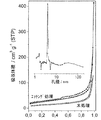
典型的なエッチング方法を図1に示す。最初に、MWNT(内径:数十 nm;外径:約100 nm;Applied Sciences Inc.、オハイオ、米国)を、還流下、濃硝酸中で2時間処理し、次いで、フェロセンから鉄を堆積させた。鉄ナノ粒子の堆積および焼結は、Xia, W.ら、Chem. Mater. 17:5737-5742 (2005)中に詳細に記載されている。本発明における鉄担持は、5〜10重量%の範囲を変動し、およびフェロセン前駆体の量を変化させることによって変化させることができる。鉄担持ナノファイバーを還元し、そして水素中で1時間、500℃にて加熱処理した。ヘリウムを、水を充填した飽和器を通過させ(室温)、および、このようにして水蒸気(1体積%)を、反応器(図2)中に導入する。水素(10体積%)を、鉄触媒を活性に維持するために使用した。CO(m/e = 28)の形成およびH2O(m/e = 18)の消費を、オンライン質量分光分析により、600℃を超える試料温度にて観察した。反応温度は、堆積した鉄粒子のサイズと相関する。大きな触媒粒子について、より高い初期温度が必要である。小さい粒子について、不活性化は非常に迅速であり、反応停止をもたらす。主に粒度および反応温度に応じて、鉄触媒を2時間まで活性化することができることが分かった。 A typical etching method is shown in FIG. First, MWNT (inner diameter: tens of nm; outer diameter: about 100 nm; Applied Sciences Inc., Ohio, USA) was treated under reflux in concentrated nitric acid for 2 hours, and then iron was deposited from ferrocene. . The deposition and sintering of iron nanoparticles is described in detail in Xia, W. et al., Chem. Mater. 17: 5737-5742 (2005). The iron loading in the present invention can be varied by varying the range of 5-10% by weight and changing the amount of ferrocene precursor. The iron-loaded nanofibers were reduced and heat treated at 500 ° C. for 1 hour in hydrogen. Helium is passed through a saturator filled with water (room temperature) and thus water vapor (1% by volume) is introduced into the reactor (FIG. 2). Hydrogen (10% by volume) was used to keep the iron catalyst active. The formation of CO (m / e = 28) and consumption of H 2 O (m / e = 18) was observed at sample temperatures above 600 ° C. by online mass spectrometry. The reaction temperature correlates with the size of the deposited iron particles. For large catalyst particles, a higher initial temperature is required. For small particles, inactivation is very rapid, resulting in reaction termination. It has been found that the iron catalyst can be activated for up to 2 hours, mainly depending on the particle size and reaction temperature.
カーボンナノファイバーの表面からの鉄粒子の除去は、Wue, P.ら、Surf. Interface Anal. 36:497-500(2004)に記載されているように、水性塩酸またはHNO3とH2SO4との混合物によって行うことができる。 Removal of iron particles from the surface of carbon nanofibers can be accomplished using aqueous hydrochloric acid or HNO 3 and H 2 SO 4 as described in Wue, P. et al., Surf. Interface Anal. 36: 497-500 (2004). Can be carried out by a mixture with.
ナノファイバーの形態を、SEMによって検査した。図4aは、未処理状態のナノファイバーを示す。エッチングされた試料中のナノファイバーの表面に埋め込まれたナノサイズ酸化鉄粒子の存在を観察することができる(図4b)。球状のエッチングピットは、鉄粒子を酸による洗浄によって除去した後、明確に見ることができる(図4c)。図5aに示す透過型電子顕微鏡写真は、エッチング方法に起因する鉄ナノ粒子の埋め込みを示す。表面粗さは、鉄ナノ粒子の洗浄除去後の透過型電子顕微鏡写真が示すように、エッチングにより顕著に増大した(図5b-c)。また、ナノファイバーの壁に対する損傷は、図5dに示す高解像度TEMにおいて見ることができる。球状の穴は、ナノファイバー中へとエッチングされていた。明らかに、外壁が逐次除去されている。 The nanofiber morphology was examined by SEM. FIG. 4a shows the nanofiber in an untreated state. The presence of nanosized iron oxide particles embedded on the surface of the nanofibers in the etched sample can be observed (FIG. 4b). Spherical etching pits can be clearly seen after the iron particles have been removed by acid cleaning (FIG. 4c). The transmission electron micrograph shown in FIG. 5a shows the embedding of iron nanoparticles due to the etching method. The surface roughness was remarkably increased by etching as shown in the transmission electron micrograph after washing and removing the iron nanoparticles (FIGS. 5b-c). Also, damage to the nanofiber walls can be seen in the high resolution TEM shown in FIG. 5d. A spherical hole was etched into the nanofiber. Obviously, the outer wall is removed sequentially.
短時間にわたるエッチングは、観察される材料特性における感知可能な変化を伴わずに、主に表面欠陥をもたらす。一方、材料特性は、エッチング時間を長くすることにより、顕著に変化し得る。図6は、1時間よりも長くエッチングされたナノファイバーについてのX線回折 (XRD)の結果を示す。未処理ナノファイバーと比較して、シグナル強度は、エッチング後に顕著に低減される。強度を結晶化度と直接的に相関させることは適切ではないが、エッチング後の不規則性の顕著な増大は、高度に再現可能なXRD結果から疑いなく導き出され得る。窒素物理吸着測定法により示すことができるように(図7)、比較的小さなメソ細孔がエッチングにより製造された。エッチングされたナノファイバーの場合、等温線の吸着ブランチと脱着ブランチとの間のヒステリシスが観察され、および数ナノメーターの孔径が推定された(図7)。このような小孔は、実質的に完全な平行壁を有する未処理MWNTにおいて検出できない。結果として、ナノファイバーの比表面積は、約20〜40 m2/gから90〜110 m2/gまで増大する。 Etching over short periods of time primarily results in surface defects without appreciable changes in observed material properties. On the other hand, the material properties can change significantly by increasing the etching time. FIG. 6 shows X-ray diffraction (XRD) results for nanofibers etched for more than 1 hour. Compared to untreated nanofibers, the signal intensity is significantly reduced after etching. Although it is not appropriate to correlate strength directly with crystallinity, a significant increase in post-etch irregularities can undoubtedly be derived from highly reproducible XRD results. Relatively small mesopores were produced by etching, as can be shown by nitrogen physisorption measurement (FIG. 7). In the case of etched nanofibers, hysteresis between the adsorption and desorption branches of the isotherm was observed and a pore size of a few nanometers was estimated (FIG. 7). Such a small hole cannot be detected in an untreated MWNT having a substantially perfect parallel wall. As a result, the specific surface area of the nanofiber increases from about 20-40 m 2 / g to 90-110 m 2 / g.
要約すれば、球状のエッチングピットを有するメソ多孔性MWNTを、環境に優しく、かつ有利な原料(鉄および水)に基づく標的局所エッチング方法で製造することができる、といえる。本発明の方法において、エッチングは、ナノファイバーの表面で起こり、および鉄粒子とナノファイバーとの間の界面に限定される。鉄粒子を含有しないナノファイバー表面の全ての部分は、エッチング方法によって変化しない。方法パラメータの単純な制御および変動は、エッチング方法を極めて柔軟性にする。可能性のある使用は、ポリマー複合体、触媒反応およびバイオセンサーの分野におけるものである。我々は、エッチングピットが堆積したナノサイズ触媒粒子の表面移動性を効果的に低減し、したがって、触媒の不活性化を導く凝集(焼結)が回避されるのを可能にする、と推定する。また、増大した表面粗さが、バイオセンサーにおける機能性タンパク質の固定に有用であること、および顕著に改善された酸素官能化を導くこと、が期待される。 In summary, it can be said that mesoporous MWNTs with spherical etching pits can be produced by a targeted local etching method based on environmentally friendly and advantageous raw materials (iron and water). In the method of the present invention, etching occurs at the surface of the nanofiber and is limited to the interface between the iron particles and the nanofiber. All portions of the nanofiber surface that do not contain iron particles are not altered by the etching method. Simple control and variation of the process parameters makes the etching method extremely flexible. Possible uses are in the field of polymer conjugates, catalysis and biosensors. We presume that etching pits effectively reduce the surface mobility of deposited nano-sized catalyst particles and thus allow agglomeration (sintering) leading to catalyst deactivation to be avoided. . It is also expected that increased surface roughness is useful for immobilizing functional proteins in biosensors and leads to significantly improved oxygen functionalization.
本発明を以下の実施例によって説明する。しかしながら、これらの実施例は、請求された主題を決して限定しない。 The invention is illustrated by the following examples. However, these examples in no way limit the claimed subject matter.
〔実施例1〕
鉄担持ナノファイバー(10重量%;Applied Sciences Inc.、Cedarville、オハイオ、米国から得ることができる)を還元し、そして水素とヘリウムとの混合物(1:1、100 ml min-1 STP)中で1時間、500℃にて熱処理した。10体積%の水素濃度および1体積%の水濃度を有する100 ml min-1 STPの総ガス流を、以下のように製造した:ヘリウム(32.3 ml min-1 STP)を、水(室温)を充填した飽和器を通過させた。水素(10 ml min-1 STP)およびさらなるヘリウム(57.7 ml min-1 STP)を、固定床の上流の反応器中で水含有ヘリウム流と組み合わせた。使用した水素(10体積%)は、鉄触媒を活性に維持するのに役立った。全てのガス流の制御は、オンライン質量分光分析(MS)で行った。水シグナル(m/e = 18)が約30分後に定常になったので、反応器を、20 K min-1の加熱速度で500℃から670℃まで加熱した。CO(m/e = 28)の形成およびH2O(m/e = 18)の消費により質量分光分析的に示されるように、反応は約600℃で始まった。約2時間のさらなる反応時間後、反応器を、ヘリウム下(100 ml min-1 STP)、10 K min-1にて450℃まで冷却した。約30分後に最小水素シグナル(m/e = 2)に到達した後、(50 ml min-1 STP)をヘリウム(50 ml min-1 STP)とともに導入し、酸化により炭素含有堆積物を除去した。酸素シグナル(m/e = 32)の質量分光分析的監視は、炭素堆積物の排除が約5分後に完了したことを示した。反応器を室温まで冷却した。エッチングされた試料(FeOx/CNF)を、攪拌しながら、1M HNO3 を用いて室温にて1時間洗浄した。その後、さらなる特徴付けのために、ろ過し、そして乾燥した。
[Example 1]
Iron-supported nanofibers (10% by weight; obtainable from Applied Sciences Inc., Cedarville, Ohio, USA) are reduced and in a mixture of hydrogen and helium (1: 1, 100 ml min −1 STP) Heat treatment was performed at 500 ° C. for 1 hour. A total gas stream of 100 ml min -1 STP with 10 vol% hydrogen concentration and 1 vol% water concentration was prepared as follows: helium (32.3 ml min -1 STP), water (room temperature) Passed through a filled saturator. Hydrogen (10 ml min -1 STP) and additional helium (57.7 ml min -1 STP) were combined with a water-containing helium stream in the reactor upstream of the fixed bed. The hydrogen used (10% by volume) helped keep the iron catalyst active. All gas flow control was performed by on-line mass spectrometry (MS). Since the water signal (m / e = 18) became steady after about 30 minutes, the reactor was heated from 500 ° C. to 670 ° C. at a heating rate of 20 K min −1 . The reaction started at about 600 ° C. as indicated by mass spectroscopic analysis by the formation of CO (m / e = 28) and consumption of H 2 O (m / e = 18). After an additional reaction time of about 2 hours, the reactor was cooled to 450 ° C. at 10 K min −1 under helium (100 ml min −1 STP). After reaching the minimum hydrogen signal (m / e = 2) after about 30 minutes, (50 ml min -1 STP) was introduced along with helium (50 ml min -1 STP) to remove carbon-containing deposits by oxidation . Mass spectroscopic monitoring of the oxygen signal (m / e = 32) showed that the elimination of carbon deposits was complete after about 5 minutes. The reactor was cooled to room temperature. The etched sample (FeO x / CNF) was washed with 1M HNO 3 at room temperature for 1 hour with stirring. It was then filtered and dried for further characterization.
〔実施例2〕
第一工程における鉄担持を5重量%に低減し、および実施例1の全ての他のパラメータを変えない場合、反応時間は、1.5時間である。
[Example 2]
If the iron loading in the first step is reduced to 5% by weight and all other parameters of Example 1 are not changed, the reaction time is 1.5 hours.
〔実施例3〕
実施例1の全ての他のパラメータを変えず、第三工程における最大温度を670℃から650℃に低減する場合、反応時間は、1時間である。
本発明の好ましい態様は、以下を包含する。
[1]炭素繊維表面をエッチングするための方法であって、
(a)酸化による炭素繊維表面の官能化工程と、
(b)官能化表面上への金属粒子の堆積工程と、
(c)水蒸気を用いる処理による表面のエッチング工程と、
(d)酸処理による金属粒子の除去工程と
を含む、方法。
[2]炭素繊維が、カーボンナノファイバーであり、特に、
(i)炭化水素から得ることができ、および/または
(ii)50〜500 nm、好ましくは約100 nmの外径を有し、および/または
(iii)10〜60 m 2 /g、好ましくは20〜40 m 2 /gの表面積を有する、
[1]に記載の方法。
[3]炭素繊維が、マイクロファイバーであり、特に、
(i)ポリアクリロニトリル(PAN)から、好ましくは熱分解により、得ることができ、および/または
(iv)3〜10 μm、好ましくは約6 μmの外径を有し、および/または
(ii)1 m 2 /g未満の表面積を有する、
[1]に記載の方法。
[4]表面の官能化を、酸化処理により、好ましくは酸化性酸とともに加熱することにより、または酸素プラズマ処理により、特に好ましくは硝酸とともに加熱することにより行う、[1]〜[3]のいずれかに記載の方法。
[5](i)金属粒子が、Fe、CoおよびNiの中から選択され、および好ましくはFeであり、および/または
(ii)金属担持が、担持カーボンナノファイバーの総重量に基づいて、1〜20重量%、好ましくは5〜10重量%であり、および/または
(iii)金属粒子の堆積を、特に100〜600℃の温度にて、繊維と、溶解した金属塩またはメタロセン、好ましくはフェロセンとを接触させ、その後、300〜800℃、好ましくは約500℃の温度にて、水素で還元することにより行う、
[1]〜[4]のいずれかに記載の方法。
[6]エッチングを、ヘリウム雰囲気中の水蒸気で処理することにより行い、
ここで好ましくは、
(i)ヘリウム雰囲気の水蒸気含量が、0.1〜10体積%、特に好ましくは約1体積%であり、および/または
(ii)エッチングを、500〜800℃、特に好ましくは600℃を超える温度にて行い、および/または
(iii)ヘリウム雰囲気が、金属触媒を活性に維持するために、1〜20体積%、好ましくは約10体積%のH 2 を含有する、
[1]〜[5]のいずれかに記載の方法。
[7]金属粒子の除去を、酸、特に水性塩酸またはHNO 3 /H 2 SO 4 の混合物によって処理することにより行う、[1]〜[6]のいずれかに記載の方法。
[8]エッチングされた炭素繊維が、90〜100 m 2 /gの比表面積を有するカーボンナノファイバーまたは5〜50 m 2 /gの比表面積を有するカーボンマイクロファイバーである、[1]〜[7]のいずれかに記載の方法。
[9][1]〜[8]のいずれかに記載の方法により得ることができる、エッチングされた炭素繊維。
[10]複合体、エネルギー貯蔵体、センサーにおける、吸着材、不均一触媒用支持体としての、およびさらなる酸素官能化後の触媒活性材料としての、[9]に記載のエッチングされた炭素繊維の使用。
Example 3
If all the other parameters of Example 1 are not changed and the maximum temperature in the third step is reduced from 670 ° C. to 650 ° C., the reaction time is 1 hour.
Preferred embodiments of the present invention include the following.
[1] A method for etching a carbon fiber surface,
(a) a functionalization process of the carbon fiber surface by oxidation;
(b) a process of depositing metal particles on the functionalized surface;
(c) a surface etching step by treatment with water vapor;
(d) a step of removing metal particles by acid treatment;
Including a method.
[2] The carbon fiber is a carbon nanofiber,
(i) can be obtained from hydrocarbons, and / or
(ii) has an outer diameter of 50-500 nm, preferably about 100 nm, and / or
(iii) having a surface area of 10-60 m 2 / g, preferably 20-40 m 2 / g,
The method according to [1].
[3] The carbon fiber is a microfiber,
(i) can be obtained from polyacrylonitrile (PAN), preferably by pyrolysis, and / or
(iv) has an outer diameter of 3-10 μm, preferably about 6 μm, and / or
(ii) having a surface area of less than 1 m 2 / g,
The method according to [1].
[4] Any of [1] to [3], wherein the functionalization of the surface is performed by oxidation treatment, preferably by heating with an oxidizing acid, or by oxygen plasma treatment, particularly preferably by heating with nitric acid. The method of crab.
[5] (i) the metal particles are selected from Fe, Co and Ni and are preferably Fe and / or
(ii) the metal loading is 1 to 20% by weight, preferably 5 to 10% by weight, based on the total weight of the supported carbon nanofibers, and / or
(iii) metal particle deposition, especially at a temperature of 100-600 ° C., contacting the fiber with a dissolved metal salt or metallocene, preferably ferrocene, followed by 300-800 ° C., preferably about 500 ° C. By reducing with hydrogen at temperature,
[1] The method according to any one of [4].
[6] Etching is performed by treating with water vapor in a helium atmosphere;
Preferably here,
(i) the water vapor content of the helium atmosphere is 0.1 to 10% by volume, particularly preferably about 1% by volume, and / or
(ii) etching is performed at a temperature of 500 to 800 ° C., particularly preferably above 600 ° C., and / or
(iii) the helium atmosphere, in order to keep the metal catalyst active, 1 to 20 vol%, preferably from about 10% by volume of H 2,
[1] The method according to any one of [5].
[7] The method according to any one of [1] to [6], wherein the metal particles are removed by treatment with an acid, particularly aqueous hydrochloric acid or a mixture of HNO 3 / H 2 SO 4 .
[8] The etched carbon fibers are carbon nanofibers having a specific surface area of 90 to 100 m 2 / g or carbon microfibers having a specific surface area of 5 to 50 m 2 / g. ] The method in any one of.
[9] An etched carbon fiber obtainable by the method according to any one of [1] to [8].
[10] The etched carbon fiber of [9] as an adsorbent, a heterogeneous catalyst support in a composite, energy storage, sensor, and as a catalytically active material after further oxygen functionalization. use.
Claims (1)
(a)酸化による炭素繊維表面の官能化工程と、
(b)官能化表面上への金属粒子の堆積工程と、
(c)水蒸気を用いる処理による表面のエッチング工程と、
(d)酸処理による金属粒子の除去工程と
を含む、方法。 A method for etching a carbon fiber surface comprising:
(a) a functionalization process of the carbon fiber surface by oxidation;
(b) a process of depositing metal particles on the functionalized surface;
(c) a surface etching step by treatment with water vapor;
(d) a step of removing metal particles by acid treatment.
Applications Claiming Priority (3)
| Application Number | Priority Date | Filing Date | Title |
|---|---|---|---|
| DE102006007208.1 | 2006-02-15 | ||
| DE102006007208A DE102006007208B3 (en) | 2006-02-15 | 2006-02-15 | Carbon fiber e.g. multi-walled nano fiber, upper surface etching method for e.g. biosensor, involves functionalizing upper surface of carbon nanofibers by oxidative treatment, where fibers are made of polyacrynitrile |
| PCT/EP2007/051364 WO2007093582A1 (en) | 2006-02-15 | 2007-02-13 | Catalytic etching of carbon fibres |
Publications (3)
| Publication Number | Publication Date |
|---|---|
| JP2009526923A JP2009526923A (en) | 2009-07-23 |
| JP2009526923A5 JP2009526923A5 (en) | 2010-04-02 |
| JP5205281B2 true JP5205281B2 (en) | 2013-06-05 |
Family
ID=37964983
Family Applications (1)
| Application Number | Title | Priority Date | Filing Date |
|---|---|---|---|
| JP2008554757A Expired - Fee Related JP5205281B2 (en) | 2006-02-15 | 2007-02-13 | Catalytic etching of carbon fiber |
Country Status (9)
| Country | Link |
|---|---|
| US (2) | US7638111B2 (en) |
| EP (1) | EP1987181B1 (en) |
| JP (1) | JP5205281B2 (en) |
| KR (1) | KR101354779B1 (en) |
| CN (1) | CN101384758B (en) |
| AT (1) | ATE449876T1 (en) |
| DE (2) | DE102006007208B3 (en) |
| ES (1) | ES2335155T3 (en) |
| WO (1) | WO2007093582A1 (en) |
Families Citing this family (10)
| Publication number | Priority date | Publication date | Assignee | Title |
|---|---|---|---|---|
| DE102006007208B3 (en) * | 2006-02-15 | 2007-07-05 | RUHR-UNIVERSITäT BOCHUM | Carbon fiber e.g. multi-walled nano fiber, upper surface etching method for e.g. biosensor, involves functionalizing upper surface of carbon nanofibers by oxidative treatment, where fibers are made of polyacrynitrile |
| TWI400195B (en) * | 2010-01-08 | 2013-07-01 | Iner Aec Executive Yuan | Method for making hydrogen storage structure |
| CN102366718A (en) * | 2011-06-28 | 2012-03-07 | 天津春发食品配料有限公司 | Stir extraction bar with carbon nanofiber coating and preparation method thereof |
| US20130028829A1 (en) * | 2011-07-28 | 2013-01-31 | Hagopian John G | System and method for growth of enhanced adhesion carbon nanotubes on substrates |
| WO2013109446A1 (en) * | 2012-01-18 | 2013-07-25 | The Trustees Of Columbia University In The City Of New York | Optoelectronic devices and methods of fabricating same |
| KR101421188B1 (en) * | 2013-04-09 | 2014-07-22 | 한국이엔에쓰 주식회사 | synthetic method of CNFs using of Fe catalyst, and CNFs by this method |
| KR102216454B1 (en) * | 2013-08-21 | 2021-02-17 | 코넬 유니버시티 | Porous carbon nanofibers and manufacturing thereof |
| KR101811764B1 (en) | 2015-08-06 | 2017-12-26 | 서울과학기술대학교 산학협력단 | Non-Pt catalyst for oxygen reduction electrode and manufacturing method thereof |
| KR102323509B1 (en) * | 2018-12-21 | 2021-11-09 | 울산과학기술원 | Composite anode active material, a method of preparing the composite anode material, and a lithium secondary battery comprising the composite anode active material |
| KR102178734B1 (en) * | 2019-03-28 | 2020-11-13 | 서울대학교 산학협력단 | Method for manufacturing carbon nanofiber complex and carbon nanofiber complex |
Family Cites Families (13)
| Publication number | Priority date | Publication date | Assignee | Title |
|---|---|---|---|---|
| DE2012284A1 (en) * | 1970-03-14 | 1971-10-07 | Bayer | Process for the manufacture of fiber products with thin carbon fibers |
| JPS5818418A (en) * | 1981-07-21 | 1983-02-03 | Toyobo Co Ltd | Preparation of active carbon fiber |
| US5124010A (en) * | 1988-12-12 | 1992-06-23 | Mitsubishi Rayon Company, Limited | Carbon fibers having modified surfaces and process for producing the same |
| JP2944246B2 (en) * | 1990-09-29 | 1999-08-30 | セントラル硝子株式会社 | Method for producing coiled carbon fiber |
| US5458784A (en) * | 1990-10-23 | 1995-10-17 | Catalytic Materials Limited | Removal of contaminants from aqueous and gaseous streams using graphic filaments |
| JP3013275B2 (en) * | 1992-04-27 | 2000-02-28 | 邦太朗 河添 | Method for modifying carbonaceous fiber |
| CN1040043C (en) * | 1994-04-29 | 1998-09-30 | 武汉大学 | Ultramicro nm electrode and ultramicro sensor |
| US5874166A (en) * | 1996-08-22 | 1999-02-23 | Regents Of The University Of California | Treated carbon fibers with improved performance for electrochemical and chemical applications |
| JPH11269763A (en) * | 1998-03-18 | 1999-10-05 | Osaka Gas Co Ltd | Surface treatment of carbon fiber |
| US6752977B2 (en) | 2001-02-12 | 2004-06-22 | William Marsh Rice University | Process for purifying single-wall carbon nanotubes and compositions thereof |
| CN1132675C (en) * | 2002-08-28 | 2003-12-31 | 武汉理工大学 | Hydrogen storing metal or alloy modified one-dimensional hydrogen storing carbon nano-material |
| US20060198956A1 (en) * | 2005-03-04 | 2006-09-07 | Gyula Eres | Chemical vapor deposition of long vertically aligned dense carbon nanotube arrays by external control of catalyst composition |
| DE102006007208B3 (en) * | 2006-02-15 | 2007-07-05 | RUHR-UNIVERSITäT BOCHUM | Carbon fiber e.g. multi-walled nano fiber, upper surface etching method for e.g. biosensor, involves functionalizing upper surface of carbon nanofibers by oxidative treatment, where fibers are made of polyacrynitrile |
-
2006
- 2006-02-15 DE DE102006007208A patent/DE102006007208B3/en not_active Expired - Fee Related
-
2007
- 2007-02-13 DE DE502007002105T patent/DE502007002105D1/en active Active
- 2007-02-13 CN CN2007800055572A patent/CN101384758B/en not_active Expired - Fee Related
- 2007-02-13 KR KR1020087020019A patent/KR101354779B1/en not_active IP Right Cessation
- 2007-02-13 AT AT07704540T patent/ATE449876T1/en active
- 2007-02-13 ES ES07704540T patent/ES2335155T3/en active Active
- 2007-02-13 US US12/278,592 patent/US7638111B2/en not_active Expired - Fee Related
- 2007-02-13 JP JP2008554757A patent/JP5205281B2/en not_active Expired - Fee Related
- 2007-02-13 WO PCT/EP2007/051364 patent/WO2007093582A1/en active Application Filing
- 2007-02-13 EP EP07704540A patent/EP1987181B1/en not_active Not-in-force
-
2009
- 2009-09-17 US US12/561,334 patent/US8354089B2/en not_active Expired - Fee Related
Also Published As
| Publication number | Publication date |
|---|---|
| JP2009526923A (en) | 2009-07-23 |
| US20090047207A1 (en) | 2009-02-19 |
| EP1987181B1 (en) | 2009-11-25 |
| WO2007093582A1 (en) | 2007-08-23 |
| CN101384758B (en) | 2011-08-03 |
| US8354089B2 (en) | 2013-01-15 |
| KR101354779B1 (en) | 2014-01-22 |
| CN101384758A (en) | 2009-03-11 |
| DE502007002105D1 (en) | 2010-01-07 |
| US7638111B2 (en) | 2009-12-29 |
| KR20080094916A (en) | 2008-10-27 |
| EP1987181A1 (en) | 2008-11-05 |
| DE102006007208B3 (en) | 2007-07-05 |
| ES2335155T3 (en) | 2010-03-22 |
| ATE449876T1 (en) | 2009-12-15 |
| US20100021368A1 (en) | 2010-01-28 |
Similar Documents
| Publication | Publication Date | Title |
|---|---|---|
| JP5205281B2 (en) | Catalytic etching of carbon fiber | |
| Rinaldi et al. | Oxidative purification of carbon nanotubes and its impact on catalytic performance in oxidative dehydrogenation reactions | |
| JP5147686B2 (en) | Nano-sized carbon material-activated carbon composite | |
| Hoekstra et al. | Base metal catalyzed graphitization of cellulose: A combined Raman spectroscopy, temperature-dependent X-ray diffraction and high-resolution transmission electron microscopy study | |
| Datsyuk et al. | Chemical oxidation of multiwalled carbon nanotubes | |
| JP2008517863A (en) | Improved ozonolysis of carbon nanotubes | |
| Xia et al. | Chemical vapor deposition and synthesis on carbon nanofibers: sintering of ferrocene-derived supported iron nanoparticles and the catalytic growth of secondary carbon nanofibers | |
| US11643328B2 (en) | Method of producing surface-treated carbon nanostructures | |
| JP2009515812A (en) | Mixed structure of single- and multi-walled carbon nanotubes | |
| JP2007077016A (en) | Hydrogen storage material and its manufacturing method, hydrogen storage method | |
| Perez-Aguilar et al. | Adsorption of cadmium and lead onto oxidized nitrogen-doped multiwall carbon nanotubes in aqueous solution: equilibrium and kinetics | |
| US20200102697A1 (en) | Sheet and method of manufacturing the same | |
| Sharma et al. | In-situ nitrogen doping in carbon nanotubes using a fluidized bed reactor and hydrogen storage behavior of the doped nanotubes | |
| Wu et al. | Effects of different palladium content loading on the hydrogen storage capacity of double-walled carbon nanotubes | |
| Deneuve et al. | Catalytic growth of silicon carbide composite with nanoscopic properties and enhanced oxidative resistance as catalyst support | |
| EP2240277A1 (en) | Processes for the recovery of catalytic metal and carbon nanotubes | |
| Yadav et al. | Advances in the application of carbon nanotubes as catalyst support for hydrogenation reactions | |
| JP2017081764A (en) | Production method of organically modified carbon material, and organically modified carbon material | |
| Capilli et al. | Non-purified commercial multiwalled carbon nanotubes supported on electrospun polyacrylonitrile@ polypyrrole nanofibers as photocatalysts for water decontamination | |
| Shamoradi et al. | Study of fabrication and CNT growth mechanisms of hybrid CFF/CNT composites | |
| Mamun et al. | Carbon nanotubes grown on oil palm shell powdered activated carbon as less hazardous and cheap substrate | |
| Diyuk et al. | Gas-Phase and Plasma-Chemical Bromination: Key Techniques to Prepare Heteroatom-Functionalized Carbon Surfaces | |
| KR20110075096A (en) | Method of preparing carbon nanotube complex structures | |
| Mosquera et al. | Studies of Multi-walled Carbon Nanotubes and Their Capabilities of Hydrogen Adsorption | |
| Sarder | Synthesis of Mechanochemically Functionalized Graphene Microparticles and Their Application for Engineering Composite Materials |
Legal Events
| Date | Code | Title | Description |
|---|---|---|---|
| A521 | Request for written amendment filed |
Free format text: JAPANESE INTERMEDIATE CODE: A523 Effective date: 20100210 |
|
| A621 | Written request for application examination |
Free format text: JAPANESE INTERMEDIATE CODE: A621 Effective date: 20100210 |
|
| A977 | Report on retrieval |
Free format text: JAPANESE INTERMEDIATE CODE: A971007 Effective date: 20120210 |
|
| A131 | Notification of reasons for refusal |
Free format text: JAPANESE INTERMEDIATE CODE: A131 Effective date: 20120214 |
|
| A521 | Request for written amendment filed |
Free format text: JAPANESE INTERMEDIATE CODE: A523 Effective date: 20120511 |
|
| A711 | Notification of change in applicant |
Free format text: JAPANESE INTERMEDIATE CODE: A711 Effective date: 20121207 |
|
| TRDD | Decision of grant or rejection written | ||
| A01 | Written decision to grant a patent or to grant a registration (utility model) |
Free format text: JAPANESE INTERMEDIATE CODE: A01 Effective date: 20130122 |
|
| A61 | First payment of annual fees (during grant procedure) |
Free format text: JAPANESE INTERMEDIATE CODE: A61 Effective date: 20130218 |
|
| R150 | Certificate of patent or registration of utility model |
Free format text: JAPANESE INTERMEDIATE CODE: R150 |
|
| FPAY | Renewal fee payment (event date is renewal date of database) |
Free format text: PAYMENT UNTIL: 20160222 Year of fee payment: 3 |
|
| LAPS | Cancellation because of no payment of annual fees |