JP5204089B2 - Correction of radioactivity measurements using particles from atmospheric sources - Google Patents
Correction of radioactivity measurements using particles from atmospheric sources Download PDFInfo
- Publication number
- JP5204089B2 JP5204089B2 JP2009500926A JP2009500926A JP5204089B2 JP 5204089 B2 JP5204089 B2 JP 5204089B2 JP 2009500926 A JP2009500926 A JP 2009500926A JP 2009500926 A JP2009500926 A JP 2009500926A JP 5204089 B2 JP5204089 B2 JP 5204089B2
- Authority
- JP
- Japan
- Prior art keywords
- value
- material body
- detectors
- detector
- measurement
- Prior art date
- Legal status (The legal status is an assumption and is not a legal conclusion. Google has not performed a legal analysis and makes no representation as to the accuracy of the status listed.)
- Expired - Fee Related
Links
- 238000005259 measurement Methods 0.000 title claims description 141
- 239000002245 particle Substances 0.000 title claims description 46
- 238000012937 correction Methods 0.000 title claims description 25
- 239000000463 material Substances 0.000 claims description 241
- 239000012857 radioactive material Substances 0.000 claims description 66
- 238000000034 method Methods 0.000 claims description 55
- 230000000694 effects Effects 0.000 claims description 15
- 238000012545 processing Methods 0.000 claims description 14
- 230000004913 activation Effects 0.000 claims description 2
- 230000001419 dependent effect Effects 0.000 claims 4
- 238000013459 approach Methods 0.000 description 11
- 238000001514 detection method Methods 0.000 description 11
- 230000008569 process Effects 0.000 description 10
- 230000005540 biological transmission Effects 0.000 description 8
- 230000006870 function Effects 0.000 description 6
- 230000008859 change Effects 0.000 description 5
- JJWKPURADFRFRB-UHFFFAOYSA-N carbonyl sulfide Chemical compound O=C=S JJWKPURADFRFRB-UHFFFAOYSA-N 0.000 description 4
- 230000014509 gene expression Effects 0.000 description 4
- 230000003993 interaction Effects 0.000 description 4
- 230000009467 reduction Effects 0.000 description 4
- 238000000926 separation method Methods 0.000 description 4
- 230000007423 decrease Effects 0.000 description 3
- 238000007689 inspection Methods 0.000 description 3
- 230000002745 absorbent Effects 0.000 description 2
- 239000002250 absorbent Substances 0.000 description 2
- 238000001739 density measurement Methods 0.000 description 2
- 230000004907 flux Effects 0.000 description 2
- 238000011835 investigation Methods 0.000 description 2
- 230000007246 mechanism Effects 0.000 description 2
- 230000003287 optical effect Effects 0.000 description 2
- 238000010521 absorption reaction Methods 0.000 description 1
- 230000008878 coupling Effects 0.000 description 1
- 238000010168 coupling process Methods 0.000 description 1
- 238000005859 coupling reaction Methods 0.000 description 1
- 238000013016 damping Methods 0.000 description 1
- 230000003247 decreasing effect Effects 0.000 description 1
- 230000005251 gamma ray Effects 0.000 description 1
- 230000006872 improvement Effects 0.000 description 1
- 238000009434 installation Methods 0.000 description 1
- 238000000691 measurement method Methods 0.000 description 1
- 230000000149 penetrating effect Effects 0.000 description 1
- 230000005258 radioactive decay Effects 0.000 description 1
- 230000002285 radioactive effect Effects 0.000 description 1
- 239000000941 radioactive substance Substances 0.000 description 1
- 238000012360 testing method Methods 0.000 description 1
Images


Classifications
-
- G—PHYSICS
- G01—MEASURING; TESTING
- G01T—MEASUREMENT OF NUCLEAR OR X-RADIATION
- G01T1/00—Measuring X-radiation, gamma radiation, corpuscular radiation, or cosmic radiation
- G01T1/16—Measuring radiation intensity
- G01T1/167—Measuring radioactive content of objects, e.g. contamination
-
- G01V5/22—
-
- G01V5/26—
Description
本発明は、例えば材料本体内から生ずる放射性物質の検出に適用される補正に関連した、検出及び改善に関する。 The present invention relates to detection and improvement, for example in connection with corrections applied to the detection of radioactive substances originating from within the material body.
本発明の第1の局面によれば、我々は、材料本体内の放射性材料の測定値を補正する方法であって、
前記放射性材料の特性を測定して測定値を提供するステップと、
前記材料本体を通過していない大気源からの1種類以上の粒子を検出して第1の値を与えるステップと、
前記材料本体を通過した大気源からの1種類以上の粒子を検出して第2の値を与えるステップと、
前記第1及び第2の値を処理して係数を与えるステップと、
前記材料本体の放射性材料の補正された測定値を得るために、前記係数を用いて前記測定値を補正するステップとを含む、方法を提供する。
According to a first aspect of the invention, we correct a measurement of radioactive material in the material body, comprising:
Measuring properties of the radioactive material and providing measurements;
Detecting one or more types of particles from an air source that has not passed through the material body to provide a first value;
Detecting one or more types of particles from an atmospheric source that have passed through the material body and providing a second value;
Processing the first and second values to provide a coefficient;
Correcting the measurement value using the coefficient to obtain a corrected measurement value of the radioactive material of the material body.
本発明の第1の局面は、本文書のその他の所に記載された特徴、選択肢若しくは可能性を含んでよい。粒子は、ミューオン若しくはミューオンにより生成される電子であってよい。 The first aspect of the invention may include features, options or possibilities described elsewhere in this document. A particle may be a muon or an electron generated by a muon.
本発明の第2の局面によれば、我々は、材料本体内の放射性材料の測定値を補正する方法であって、
前記放射性材料の特性を測定して測定値を提供するステップと、
前記材料本体を通過していないミューオンにより生成された電子及び/又はミューオンを検出して第1の値を与えるステップと、
前記材料本体を通過したミューオンにより生成された電子及び/又はミューオンを検出して第2の値を与えるステップと、
前記第1及び第2の値を処理して係数を与えるステップと、
前記材料本体の放射性材料の補正された測定値を得るために、前記係数を用いて前記測定値を補正するステップとを含む、方法を提供する。
According to a second aspect of the invention, we correct a measurement of radioactive material in the material body,
Measuring properties of the radioactive material and providing measurements;
Detecting electrons and / or muons generated by muons not passing through the material body to provide a first value;
Detecting electrons and / or muons generated by the muons that have passed through the material body to provide a second value;
Processing the first and second values to provide a coefficient;
Correcting the measurement value using the coefficient to obtain a corrected measurement value of the radioactive material of the material body.
本発明の第2の局面は、本文書のその他の所に記載された特徴、選択肢若しくは可能性を含んでよい。 The second aspect of the invention may include features, options or possibilities as described elsewhere in this document.
本発明の第3の局面によれば、我々は、材料本体内の放射性材料の測定値を補正する方法であって、
前記放射性材料の特性を調査するステップと、
前記材料本体を通過していないミューオンを直接検出して第1の値を与えるステップと、
前記材料本体を通過したミューオンを直接検出して第2の値を与えるステップと、
前記第1及び第2の値を考慮して係数を与えるステップと、
前記材料本体の放射性材料の特性の調査を改善するために、前記係数を用いるステップとを含む、方法を提供する。
According to a third aspect of the present invention, we provide a method of correcting a measurement of radioactive material in a material body comprising:
Investigating the properties of the radioactive material;
Directly detecting muons not passing through the material body to provide a first value;
Directly detecting a muon that has passed through the material body to provide a second value;
Providing a coefficient in consideration of the first and second values;
Using the coefficient to improve the investigation of the properties of the radioactive material of the material body.
本発明の第3の局面は、本文書のその他の所に記載された特徴、選択肢若しくは可能性を含んでよい。調査は、好ましくは測定値を得るために、特性の測定であってよい。係数は、前記材料本体の放射性材料の補正された測定値を得るために、前記測定値を補正するために使用されてもよい。 The third aspect of the present invention may include features, options or possibilities described elsewhere in this document. The investigation may be a measurement of properties, preferably to obtain a measurement value. A factor may be used to correct the measurement to obtain a corrected measurement of the radioactive material of the material body.
第1及び/又は第2及び/又は第3の局面は、次の任意の特徴、選択肢若しくは可能性を含んでよい。 The first and / or second and / or third aspects may include any of the following features, options or possibilities:
前記材料本体内の放射性材料の測定値は、密度に対して補正されてもよい。前記材料本体内の放射性材料の測定値は、減衰に対して補正されてもよい。前記材料本体内の放射性材料の測定値は、例えば放射性材料による自己遮蔽及び/又は非放射性材料による遮蔽のような、遮蔽に対して補正されてもよい。測定値は、密度、減衰若しくは遮蔽の1つ以上に対して補正されてもよい。 The measurement of radioactive material in the material body may be corrected for density. The measurement of the radioactive material in the material body may be corrected for attenuation. The measurement of radioactive material in the material body may be corrected for shielding, for example self-shielding with radioactive material and / or shielding with non-radioactive material. The measured value may be corrected for one or more of density, attenuation or shielding.
材料本体は、材料に対する容器を含んでよい。容器は、貯蔵容器であってよい。容器は、輸送可能な容器であってよい。容器は、ISO貨物容器、七分高さのISO貨物容器、半分の高さのISO貨物容器、若しくは、3番目の高さのISO貨物容器であってよい。容器は、インターモデル(Intermodel)若しくはその部分サイズであってよい。材料本体は、1つ以上の放射性材料を含んでよい。 The material body may include a container for the material. The container may be a storage container. The container may be a transportable container. The container may be an ISO cargo container, a seven-high ISO cargo container, a half-height ISO cargo container, or a third-high ISO cargo container. The container may be an Intermodel or a partial size thereof. The material body may include one or more radioactive materials.
本方法は、容器及びその材料本体の重量及び/又は質量を計測するステップを含んでよい。本方法は、容器及びその材料本体の正味重量及び/又は正味質量を測定してもよい。本方法は、材料本体の正味重量及び/又は正味質量を測定してもよい。重量若しくは質量は、測定位置及び/又はその他の位置で計測されてもよい。 The method may include measuring the weight and / or mass of the container and its material body. The method may measure the net weight and / or net mass of the container and its material body. The method may measure the net weight and / or net mass of the material body. The weight or mass may be measured at the measurement location and / or other locations.
本方法は、容器及びその材料本体の計測密度若しくは材料本体単体の計測密度を計測するステップを含んでよい。密度の計測は、容器における材料本体の充填度合いを考慮してもよい。充填度合いは、検査及び測定及び/又は検査及び推定及び/又は測定単独により計測されてもよい。充填度合いは、送信源を用いて、材料本体及び/又は容器の他方の側の検出器により測定されてもよい。 The method may include measuring the measured density of the container and its material body or the measured density of the material body alone. The density measurement may take into account the degree of filling of the material body in the container. The degree of filling may be measured by inspection and measurement and / or inspection and estimation and / or measurement alone. The degree of filling may be measured by a detector on the other side of the material body and / or container using a transmission source.
前記材料本体内の放射性材料の測定値は、前記材料本体の異なる部分に対して異なる態様で補正されてもよい。1つ以上の異なる部分は、粒子用の検出器の視野及び/又は視野の一部及び/又は2つ以上の検出器の視野の共通部分であってよい。2つの検出器の視野の共通部分は、第1の視野と第2の視野内に存在する部分であってよい。 The measurement of the radioactive material in the material body may be corrected in different ways for different parts of the material body. The one or more different portions may be a detector field for particles and / or a portion of the field of view and / or a common part of two or more detector fields of view. The common part of the field of view of the two detectors may be the part present in the first field and the second field.
本発明の一実施例では、第1の視野と第2の視野の一方は、測定位置を見る検出器の視野及び/又は下方から材料本体を見る検出器の視野であってよく、第1の視野と第2の視野の他方は、測定位置を見る検出器の視野及び/又は側方から材料本体を見る検出器の視野であってよい。 In one embodiment of the present invention, one of the first field and the second field may be a field of view of the detector viewing the measurement position and / or a field of view of the detector viewing the material body from below, The other of the field of view and the second field of view may be the field of view of the detector viewing the measurement location and / or the field of view of the detector viewing the body of material from the side.
第1の視野と第2の視野の使用は、単一の視野の考慮から存在する不明瞭の解明を補助することができる。第1の視野と第2の視野の考慮は同時に生じてもよい。 The use of the first and second fields of view can help resolve the ambiguities that exist from a single field of view consideration. Consideration of the first field of view and the second field of view may occur simultaneously.
その他の実施例では、第1の視野と第2の視野の考慮は、第1の時間と第2の異なる時間に生じてもよい。1つ以上の検出器、より好ましくは材料本体は、第1の時間と第2の時間の間で向きが変化されてもよい。向きの変化は、第1の時間と第2の時間の間で検出器を超えて前進する容器及び/又は材料本体に起因して生じてもよい。好ましくは、容器及び/又は材料本体は、第1の時間中及び/又は第2の時間中、固定される。向きの変化は、第1の時間と第2の時間の間で容器及び/又は材料本体を超えて前進する検出器に起因して生じてもよい。好ましくは、検出器は、第1の時間中及び/又は第2の時間中、固定される。向きの変化は、例えば90度、回転に起因して生じてもよい。 In other embodiments, consideration of the first field of view and the second field of view may occur at a first time and a second different time. One or more detectors, and more preferably the body of material, may change orientation between the first time and the second time. The change in orientation may occur due to the container and / or material body moving forward beyond the detector between the first time and the second time. Preferably, the container and / or the material body are fixed during the first time and / or during the second time. The change in orientation may occur due to a detector moving past the container and / or material body between a first time and a second time. Preferably, the detector is fixed during the first time and / or during the second time. The change in orientation may occur due to rotation, for example 90 degrees.
材料本体は、直線容積(レクティリニア・ボリューム)であってよい。1つ以上の異なる部分は、例えば直線セグメントのような、材料本体のセグメントであってよい。材料本体は、複数のセグメントから形成されてもよい。好ましくは、各セグメントは、材料本体の完全な高さ及び/又は幅に延在し、及び/又は、完全な長さに延在しない。1つのセグメントは、1つ以上の異なる部分を含んでよい。好ましくは、材料本体及び/又はセグメント及び/又は各セグメントは、第1の検出器及び第2の検出器の数の倍数である多数の異なる部分を含む。材料本体は、5から25つの間のかかるセグメント、より好ましくは8から18つのセグメント、理想的には10から16つのセグメントとして考慮されてもよい。 The material body may be a linear volume. One or more different parts may be segments of the body of material, for example straight segments. The material body may be formed from a plurality of segments. Preferably, each segment extends to the full height and / or width of the material body and / or does not extend to the full length. A segment may include one or more different parts. Preferably, the material body and / or segment and / or each segment comprises a number of different parts that are multiples of the number of first detectors and second detectors. The body of material may be considered as between 5 and 25 such segments, more preferably 8 to 18 segments, ideally 10 to 16 segments.
放射性材料の特性の測定は、放射性材料による放出物の直接及び/又は間接の測定であってよい。放出物は、特には、ガンマ線であってよい。1つ以上のガンマ線エネルギが考慮されてもよい。測定は、放出物検出器によりなされてもよい。放出物検出器は、第1の検出器及び/又は第2の検出器とは異なってもよいが、好ましくは第1の検出器と同一である。 The measurement of the properties of the radioactive material may be a direct and / or indirect measurement of the emission by the radioactive material. The emission may in particular be gamma rays. One or more gamma ray energies may be considered. The measurement may be made with an emissions detector. The emission detector may be different from the first detector and / or the second detector, but is preferably the same as the first detector.
測定値は、カウント値及び/又はカウント率及び/又は活性化レベル及び/又は質量等価値であってよい。 The measured value may be a count value and / or a count rate and / or an activation level and / or a mass equivalent value.
1種類以上の粒子は、ミューオンを含んでよい。1種類以上の粒子は、ミューオンにより生成された電子を含んでよい。1種類以上の粒子は、ミューオンのみであってもよい。 One or more types of particles may include muons. One or more types of particles may include electrons generated by muons. One or more types of particles may be muons only.
大気源は、地球の大気、特には、上層の大気の、1種類以上の宇宙線との相互作用であってよい。 The atmospheric source may be the interaction of one or more types of cosmic rays with the Earth's atmosphere, particularly the upper atmosphere.
粒子は、材料本体から500メートルを超えて上昇してもよい。 The particles may rise more than 500 meters from the material body.
第1の値は、材料本体が存在しない状態で、測定位置及び/又は材料本体の下方に設けられる1つ以上の第1の検出器から取得されてもよい。好ましくは、第1の値は、測定位置及び/又は材料本体の上方に設けられる1つ以上の第2の検出器から取得される。第1の値は、材料本体が測定位置に無い状態で1つ以上の第2の検出器から取得されてもよいが、好ましくは、材料本体が測定位置にある状態で取得される。 The first value may be obtained from one or more first detectors provided below the measurement position and / or the material body in the absence of the material body. Preferably, the first value is obtained from one or more second detectors provided above the measurement position and / or the material body. The first value may be obtained from one or more second detectors without the material body in the measurement position, but is preferably obtained with the material body in the measurement position.
第2の値は、材料本体が存在する状態で、測定位置及び/又は材料本体の下方に設けられる1つ以上の第1の検出器から取得されてもよい。第2の値は、1つ以上の第1の検出器からのみ取得されてもよい。第2の値は、1つ以上の第3の検出器と協動して、1つ以上の第1の検出器から取得されてもよい。1つ以上の第3の検出器は、好ましくは、測定位置及び/又は材料本体の下方に設けられる。1つ以上の第3の検出器は、好ましくは、1つ以上の第1の検出器の下方に設けられる。第2の値は、1つ以上の第2の検出器と協動して、1つ以上の第1の検出器から取得されてもよい。第2の値が1つ以上の第1の検出器及び1つ以上の第3の検出器若しくは1つ以上の第1の検出器及び1つ以上の第2の検出器から取得される場合、第2の値は、第1及び第3の検出器若しくは第1及び第2の検出器の双方と相互作用するミューオン又は電子のカウント値及び/又はカウント率であってよい。 The second value may be obtained from one or more first detectors provided below the measurement location and / or the material body in the presence of the material body. The second value may be obtained only from one or more first detectors. The second value may be obtained from one or more first detectors in cooperation with one or more third detectors. One or more third detectors are preferably provided below the measurement position and / or the material body. One or more third detectors are preferably provided below the one or more first detectors. The second value may be obtained from one or more first detectors in cooperation with one or more second detectors. If the second value is obtained from one or more first detectors and one or more third detectors or one or more first detectors and one or more second detectors; The second value may be a muon or electron count value and / or count rate that interacts with the first and third detectors or both the first and second detectors.
粒子は、1つ以上の第2の検出器を設けることにより材料本体を通過せずに検出されてもよい。1つ以上の第2の検出器は、材料本体に対する測定位置及び/又は材料本体の25メートル以内に設けられてよい。好ましくは、1つ以上の第2の検出器は、材料本体の2メートル以内に設けられ及び/又は材料本体の上方に設けられ、理想的には材料本体の鉛直方向上方に設けられる。好ましくは、粒子は、測定位置に材料本体がある状態で及び/又は粒子が材料本体を通過して検出されるのと同時に、1つ以上の第2の検出器により材料本体を通過せずに検出される。 The particles may be detected without passing through the body of material by providing one or more second detectors. One or more second detectors may be provided at a measurement location relative to the material body and / or within 25 meters of the material body. Preferably, the one or more second detectors are provided within 2 meters of the material body and / or above the material body, ideally vertically above the material body. Preferably, the particles do not pass through the material body by means of one or more second detectors with the material body in the measurement position and / or at the same time as the particles are detected through the material body. Detected.
第2の検出器は、各第1の検出器に対して設けられてよい。好ましくは、第2の検出器は、測定位置の材料本体若しくは測定位置それ故に第1及び第2の検出器の間で、第1の検出器の鉛直上方に設けられる。 A second detector may be provided for each first detector. Preferably, the second detector is provided vertically above the first detector, between the material body of the measurement position or between the first and second detectors.
第1及び第2の検出器は、同一種類であってよく、好ましくは互いに同一である。第1及び第2の検出器は、好ましくは、ミューオン及びガンマ線に感応性がある。第1及び/又は第2の検出器は、シンチレータ、例えばプラスティックシンチレータであってよい。 The first and second detectors may be of the same type and are preferably identical to each other. The first and second detectors are preferably sensitive to muons and gamma rays. The first and / or second detector may be a scintillator, such as a plastic scintillator.
複数の第1及び/又は第2の検出器が設けられてよく、好ましくは対で設けられる。3つ若しくは4つの検出器は、好ましくは、測定位置の上方に設けられる。3つ若しくは4つの検出器は、好ましくは、測定位置の下方に設けられる。検出器は、2つ以上の検出器から形成されてもよく、それらの出力は1つのものと看做される。 A plurality of first and / or second detectors may be provided, preferably in pairs. Three or four detectors are preferably provided above the measurement position. Three or four detectors are preferably provided below the measurement position. The detector may be formed from two or more detectors and their outputs are considered as one.
好ましくは、1つ以上の検出器、理想的には全ての検出器は、前記材料本体の前記容器の一部及び/又は測定位置の縁部の2m以内に設けられる。好ましくは、1つ以上の検出器、理想的には全ての検出器は、1.5m以内に設けられ、更に好ましくは、前記材料本体の前記容器の一部及び/又は測定位置の縁部の1m以内に設けられる。1つ以上の検出器の位置は調整可能であってよい。 Preferably, one or more detectors, ideally all detectors, are provided within 2 m of the part of the container of the material body and / or the edge of the measurement position. Preferably, one or more detectors, ideally all detectors, are provided within 1.5 m, more preferably part of the container of the material body and / or the edge of the measuring position. It is provided within 1m. The position of the one or more detectors may be adjustable.
粒子は、測定位置に材料本体が存在しない状態で検出を提供することにより材料本体を通過せずに検出されてもよい。粒子は、材料本体が測定位置に導入される前及び/又は材料本体が測定値から除去された後のような検出を実行することにより、材料本体を通過せずに検出されてもよい。 The particles may be detected without passing through the material body by providing detection in the absence of the material body at the measurement location. The particles may be detected without passing through the material body by performing detection such as before the material body is introduced into the measurement location and / or after the material body has been removed from the measurement.
好ましくは、第1及び第2の値の双方は、互いに同一の場所及び/又は同一の時間での測定により取得される。 Preferably, both the first and second values are obtained by measurement at the same location and / or at the same time.
粒子は、測定位置及び/又は材料本体の一方の側に1つ以上の検出器を設けることによって、材料本体を通過して検出されてもよい。好ましくは、1つ以上の検出器は、材料本体及び/又は測定値の下方に設けられる。好ましくは、1つ以上の検出器は、材料本体の1メートル以内に設けられ及び/又は材料本体の下方に設けられ、理想的には材料本体の鉛直下方に設けられる。好ましくは、粒子は、測定位置に材料本体がある状態で及び/又は粒子が材料本体を通過せずに検出されるのと同時に、1つ以上の第1の検出器により材料本体を通過して検出される。 The particles may be detected through the material body by providing one or more detectors on one side of the measurement location and / or the material body. Preferably, one or more detectors are provided below the material body and / or measurements. Preferably, the one or more detectors are provided within 1 meter of the material body and / or below the material body, ideally vertically below the material body. Preferably, the particles are passed through the material body by one or more first detectors with the material body in the measurement position and / or at the same time as the particles are detected without passing through the material body. Detected.
第1の値は、カウント率及び/又はカウント値及び/又はエネルギ値及び/又はエネルギ分布であってよい。 The first value may be a count rate and / or a count value and / or an energy value and / or an energy distribution.
第2の値は、カウント率及び/又はカウント値及び/又はエネルギ値及び/又はエネルギ分布であってよい。好ましくは、第1及び第2の値は、同一の種類である。 The second value may be a count rate and / or a count value and / or an energy value and / or an energy distribution. Preferably, the first and second values are of the same type.
第1及び第2の値は、1つ以上の第1の値及び1つ以上の第2の値に基づいて係数を付与するために処理されてもよい。第2の値のエネルギ分布と第1の値のエネルギ分布の間の変化は、係数に到達するために処理されてもよい。例えばエネルギとしての、第1の値と第2の値の変化は、係数に到達するために使用されてもよい。係数は、複数の第1の値及び/又は複数の第2の値の処理の結果、例えば複数の対の第1及び第2の値の処理の結果であってよい。 The first and second values may be processed to provide a coefficient based on the one or more first values and the one or more second values. Changes between the second value energy distribution and the first value energy distribution may be processed to arrive at a coefficient. Changes in the first and second values, for example as energy, may be used to reach the coefficient. The coefficient may be a result of processing a plurality of first values and / or a plurality of second values, for example, a result of processing a plurality of pairs of first and second values.
第1の値及び/又は第2の値は、第1の検出器及び/又は第2の検出器により検出される全ての粒子に対して考慮されてもよい。第1の値及び/又は第2の値は、第1の検出器及び第2の検出器を通過し及び/又はそれらと相互作用する粒子に対して考慮されてもよい。好ましくは、第1の値及び/又は第2の値は、第1の検出器及び第2の検出器を通過し及び/又はそれらと相互作用する粒子のみに対して考慮される。好ましくは、同時に起こる粒子のみが考慮される。 The first value and / or the second value may be considered for all particles detected by the first detector and / or the second detector. The first value and / or the second value may be considered for particles that pass through and / or interact with the first detector and the second detector. Preferably, the first value and / or the second value are only considered for particles that pass through and / or interact with the first detector and the second detector. Preferably only concurrent particles are considered.
本発明の一実施例では、第1の検出器は、材料本体及び/又は測定位置の下方に設けられてよく、材料本体が測定位置に存在しないときに第2の検出器として機能する。 In one embodiment of the present invention, the first detector may be provided below the material body and / or the measurement position and functions as a second detector when the material body is not present at the measurement position.
本発明のその他の一実施例では、第1の検出器は、第2の検出器が材料本体及び/又は測定位置の上方に設けられる状態で、材料本体及び/又は測定位置の下方に設けられてよい。 In another embodiment of the invention, the first detector is provided below the material body and / or measurement position, with the second detector provided above the material body and / or measurement position. It's okay.
本発明のその他の一実施例では、1つ以上の第1の検出器は、1つ以上の第3の検出器が材料本体の下方に且つ好ましくは第1の検出器の下方に設けられる状態で、材料本体及び/又は測定位置の下方に設けられてよい。好ましくは、第1の検出器の1つ及び第3の検出器の1つを通過し若しくはそれらと相互作用する粒子のみが第2の値を得る際に使用される。第1の値は、好ましくは材料本体の上方に設けられる、1つ以上の第2の検出器から取得されてもよい。 In another embodiment of the invention, the one or more first detectors are provided with one or more third detectors provided below the material body and preferably below the first detector. And may be provided below the material body and / or the measurement position. Preferably, only particles that pass through or interact with one of the first detector and one of the third detector are used in obtaining the second value. The first value may be obtained from one or more second detectors, preferably provided above the material body.
本発明のその他の一実施例では、1つ以上の、好ましくは複数の第1の検出器は、材料本体及び/又は測定位置の下方に設けられてよく、1つ以上の、好ましくは複数の第2の検出器が材料本体の上方に設けられる。好ましくは、第1の検出器及び第2の検出器を通過し若しくはそれらと相互作用する粒子のみが第2の値及び/又は第2の値を得る際に使用される。 In another embodiment of the invention, one or more, preferably a plurality of first detectors may be provided below the material body and / or the measurement position, and one or more, preferably a plurality of, detectors. A second detector is provided above the material body. Preferably, only particles that pass through or interact with the first detector and the second detector are used in obtaining the second value and / or the second value.
特に好ましい実施例は、材料本体及び/又は測定位置の下方に3つ若しくは4つの第1の検出器を設けると共に、材料本体の上方に3つ若しくは4つの第2の検出器を設ける。好ましくは、第1の検出器及び第2の検出器を通過し若しくはそれらと相互作用する粒子のみが第2の値及び/又は第2の値を得る際に使用される。 Particularly preferred embodiments provide three or four first detectors below the material body and / or measurement position and three or four second detectors above the material body. Preferably, only particles that pass through or interact with the first detector and the second detector are used in obtaining the second value and / or the second value.
係数は、密度若しくは密度に基づく係数であってよい。 The coefficient may be a density or a coefficient based on density.
1つの考えられる形態では、第2の値の第1の値に対する比、若しくはその逆の比は、材料本体に対する密度の指示値若しくは測定値を提供してよく、より好ましくは材料本体のセグメントに対する密度の指示値若しくは測定値を提供してよい。異なる密度値は、異なるセグメントに対して計測されてもよい。 In one possible form, the ratio of the second value to the first value, or vice versa, may provide an indication or measurement of the density relative to the material body, more preferably relative to the segment of the material body. An indication or measurement of density may be provided. Different density values may be measured for different segments.
その他の考えられる形態では、第1の値及び第2の値において観測される同時計数値の第1の値に対する比、若しくはその逆の比は、材料本体に対する密度の指示値若しくは測定値を提供してよく、より好ましくは材料本体のセグメントに対する密度の指示値若しくは測定値を提供してよい。第1の値は、好ましくは、ミューオンの背景レベルの測度である。同時計数値は、好ましくは、材料本体、若しくはそのセグメントの、ミューオンのレベルに対する影響の測度である。異なる密度値は、異なるセグメントに対して計測されてもよい。 In other possible forms, the ratio of the same clock value observed at the first and second values to the first value, or vice versa, provides an indication or measurement of the density relative to the material body. More preferably, an indication or measurement of the density for a segment of the material body may be provided. The first value is preferably a measure of the muon background level. The clock value is preferably a measure of the influence of the material body, or segment thereof, on the muon level. Different density values may be measured for different segments.
その他の考えられる形態では、第1の検出器及び第3の検出器から得られる同時計数値の第1の値に対する比、若しくはその逆の比は、材料本体に対する密度の指示値若しくは測定値を提供してよく、より好ましくは材料本体のセグメントに対する密度の指示値若しくは測定値を提供してよい。第1の値は、好ましくは、ミューオンの背景レベルの測度である。同時計数値は、好ましくは、材料本体、若しくはそのセグメントの、ミューオンのレベルに対する影響の測度である。異なる密度値は、異なるセグメントに対して計測されてもよい。 In other possible forms, the ratio of the same clock value obtained from the first detector and the third detector to the first value, or vice versa, is an indication or measurement of the density relative to the material body. It may be provided, more preferably an indication or measurement of the density for a segment of the material body. The first value is preferably a measure of the muon background level. The clock value is preferably a measure of the influence of the material body, or segment thereof, on the muon level. Different density values may be measured for different segments.
第1の値及び第2の値内から得られる同時計数値の比が考慮されてもよい。第1の値及び第2の値内から得られる同時計数値の第1の値に対する比が考慮されてもよい。同時計数値は、測定位置若しくは材料本体の下方に設けられる第1の検出器(複数も可)及び第3の検出器(複数も可)から取得されてもよいが、好ましくは、測定位置若しくは材料本体の下方に設けられる第1の検出器(複数も可)及び測定位置若しくは材料本体の上方に設けられる第2の検出器(複数も可)から取得される。第1の値は、好ましくは、ミューオンの背景レベルの測度である。同時計数値は、好ましくは、材料本体、若しくはそのセグメントの、ミューオンのレベルに対する影響の測度である。同時計数値の第1の値に対する比は、好ましくは分数で表現される。 A ratio of the same clock value obtained from the first value and the second value may be considered. A ratio of the same clock value obtained from the first value and the second value to the first value may be considered. The clock value may be obtained from the first detector (s) and the third detector (s) provided below the measurement position or material body, but preferably the measurement position or Obtained from a first detector (s) provided below the material body and a second detector (s) provided above the measurement position or material body. The first value is preferably a measure of the muon background level. The clock value is preferably a measure of the influence of the material body, or segment thereof, on the muon level. The ratio of the clock value to the first value is preferably expressed in fractions.
第1の値は、処理ステップで使用される前に補正されてもよい。第1の値は、検出器の幾何的配置の影響、特に第2の値を得るために用いられる第1及び第2の検出器の対及び/又は第1及び第3の検出器の対に関する幾何的配置の影響に対して補正されてもよい。処理ステップは、第1の値及び第2の値内から得られる同時計数値の比の考慮、より詳細には、第1の値及び第2の値内から得られる同時計数値の第1の値に対する比の考慮であってよい。 The first value may be corrected before being used in the processing step. The first value relates to the influence of the detector geometry, in particular the first and second detector pair and / or the first and third detector pair used to obtain the second value. You may correct | amend with respect to the influence of geometric arrangement. The processing step takes into account the ratio of the same clock value obtained from within the first value and the second value, more specifically the first of the same clock value obtained from within the first value and the second value. It may be a consideration of the ratio to the value.
別々の補正は、第1の値のそれぞれに対して付与されてもよい。好ましくは、別々の補正は、各第1の値に対して付与され、この補正は、第2の値を与える第1及び第2の検出器の対及び/又は第2の値を与える第1及び第3の検出器の対に特有のものである。 A separate correction may be applied to each of the first values. Preferably, a separate correction is applied to each first value, the correction being a first and second detector pair that provides a second value and / or a first that provides a second value. And a third detector pair.
好ましくは、第1の値は、第2の検出器を通過するが、検出器間に容器及び材料本体及び/又は材料本体が存在しない状態で第1の検出器を通過しない粒子の部分を、考慮するために補正される。好ましくは、第1の値は、特定の第2の検出器を通過するが、検出器間に容器及び材料本体及び/又は材料本体が存在しない状態で特定の第1の検出器を通過しない粒子の部分を、考慮するために補正される。 Preferably, the first value is the portion of particles that pass through the second detector but does not pass through the first detector in the absence of a container and material body and / or material body between the detectors, Corrected to take into account. Preferably, the first value is a particle that passes through the specific second detector but does not pass through the specific first detector in the absence of a container and material body and / or material body between the detectors. This part is corrected to take into account.
補正は、第1及び第2の検出器若しくは第1及び第3の検出器の相対間隔及び/又は向きを考慮してもよい。補正は、第1及び/又は第2及び/又は第3の検出器の深さ及び/又は幅及び/又は長さのような、形状を考慮してもよい。 The correction may take into account the relative spacing and / or orientation of the first and second detectors or the first and third detectors. The correction may take into account the shape, such as the depth and / or width and / or length of the first and / or second and / or third detectors.
補正は、試験的に計測されてもよい。好ましくは、1つ以上の補正係数が試験的に計測される。好ましくは、第2の検出器に対する補正係数は、第1の検出器との第2の検出器の各対に対して計測される。好ましくは、これは、各第2の検出器に対して繰り返される。好ましくは、第1の検出器に対する補正係数は、第3の検出器との第1の検出器の各対に対して計測される。好ましくは、これは、各第1の検出器に対して繰り返される。 The correction may be measured experimentally. Preferably, one or more correction factors are measured experimentally. Preferably, the correction factor for the second detector is measured for each pair of second detectors with the first detector. Preferably this is repeated for each second detector. Preferably, the correction factor for the first detector is measured for each pair of first detectors with a third detector. Preferably this is repeated for each first detector.
好ましくは、補正は、1つ以上の第1及び/又は第2及び/又は第3の検出器を、材料本体内の放射性材料を調査するために使用されるときと同一の幾何的配置で設け、材料本体の不在下で第1の値及び第2の値を取得することによって、試験的に計測される。第1の値及び第2の値は、少なくとも6時間の期間に亘って取得され、好ましくは少なくとも12時間、より好ましくは少なくとも20時間、理想的には40時間に亘って取得される。 Preferably, the correction is provided with one or more first and / or second and / or third detectors in the same geometric arrangement as used for investigating radioactive material in the material body. , Measured experimentally by obtaining a first value and a second value in the absence of the material body. The first and second values are obtained over a period of at least 6 hours, preferably at least 12 hours, more preferably at least 20 hours, ideally over 40 hours.
好ましくは分数としての、同時計数値の第1の値に対する比は、前記第2の検出器を通過する粒子、及び、前記材料本体及び/又は容器及び材料本体が無い場合に前記第1の検出器を通過することになるだろう経路、に対する前記材料本体及び/又は容器及び材料本体の影響を考慮するために用いられ、若しくは、前記第1の検出器を通過する粒子、及び、前記材料本体及び/又は容器及び材料本体が無い場合に前記第3の検出器を通過することになるだろう経路、に対する前記材料本体及び/又は容器及び材料本体の影響を考慮するために用いられる。好ましくは分数としての、同時計数値の第1の値に対する比は、材料本体若しくはそのセグメントに対する面密度の表現、理想的には面密度を算出するために使用されてもよい。 Preferably, the ratio of the co-clock value to the first value, as a fraction, is the first detection in the absence of particles passing through the second detector and the material body and / or container and material body. Particles used to take into account the influence of the material body and / or container and material body on the path that would pass through the vessel, or the particles passing through the first detector, and the material body And / or is used to take into account the influence of the material body and / or container and material body on the path that would pass through the third detector in the absence of the container and material body. The ratio of the clock value to the first value, preferably as a fraction, may be used to represent the surface density for the material body or segment thereof, ideally to calculate the surface density.
面密度若しくは面密度の表現の算出は、ルックアップテーブル若しくは公式を使用してもよい。ルックアップテーブル若しくは公式は、好ましくは、試験的に導出される。算出は、分数を面密度に直接変換してもよい。 The calculation of the surface density or the expression of the surface density may use a look-up table or a formula. The lookup table or formula is preferably derived on a trial basis. The calculation may be performed by directly converting the fraction into the surface density.
2つ以上の第1の検出器及び/又は2つ以上の第2の検出器及び/又は2つ以上の第3の検出器が設けられる場合、好ましくは、同時計数値の第1の値に対する比は、2つ以上の異なる対の検出器に対して考慮される。対は、第1及び第3の検出器の形態であってよいが、好ましくは、第1及び第2の検出器の形態である。好ましくは、面密度の表現の算出、理想的には面密度の算出は、2つ以上の対に対して付与される。好ましくは、面密度の表現の算出、理想的には面密度の算出は、各考えられる対の検出器に対して付与される。 Where two or more first detectors and / or two or more second detectors and / or two or more third detectors are provided, preferably for the first value of the same clock value The ratio is considered for two or more different pairs of detectors. The pair may be in the form of first and third detectors, but is preferably in the form of first and second detectors. Preferably, the calculation of the expression of the surface density, ideally the calculation of the surface density is given to two or more pairs. Preferably, the calculation of the expression of the surface density, ideally the calculation of the surface density, is applied to each possible pair of detectors.
好ましくは、複数の面密度の表現、理想的には複数の面密度は、材料本体に対して、若しくは、より好ましくは材料本体の各セグメントに対して取得される。好ましくは、面密度の表現、理想的には面密度は、材料本体用若しくはより好ましくはその各セグメント用の、第1及び第2の検出器の各考えられる対及び/又は第1及び第3の検出器の各考えられる対に対して取得される。 Preferably, a plurality of surface density representations, ideally a plurality of surface densities, are obtained for the material body, or more preferably for each segment of the material body. Preferably, the representation of the surface density, ideally the surface density is the respective pair and / or the first and third of the first and second detectors for the material body or more preferably for each segment thereof. For each possible pair of detectors.
好ましくは、複数の面密度の表現若しくは面密度が材料本体に対して若しくはより好ましくはセグメントに対して取得される場合、これらの表現若しくは面密度は、結合された面密度の表現若しくは結合された面密度を与えるために結合される。好ましくは、材料本体若しくはセグメントに対する全ての表現若しくは密度が結合される。9つの表現若しくは密度が使用されてもよく、より好ましくは16つの表現若しくは密度である。好ましくは、結合された密度の表現若しくは結合された密度は、2つ以上の表現若しくは密度の重み付け結合から得られる。好ましくは、重み付けは、検出器対間の材料本体を介した経路長、検出器対の検出器の鉛直方向の離隔距離、検出器対の検出器間に存在する実効容積、及び、検出器の当該対に対する計数率の精度値、のうちの1つ以上の考慮を伴う。結合された面密度表現若しくは結合された面密度は、少なくとも5つのセグメントのそれぞれに対して得られてよく、より好ましくは少なくとも10つのそれぞれ、理想的には少なくとも16つのセグメントのそれぞれに対して得られる。 Preferably, if multiple surface density representations or surface densities are obtained for a material body or more preferably for a segment, these representations or surface densities are combined surface density representations or combined Combined to give areal density. Preferably all representations or densities for the material body or segment are combined. Nine representations or densities may be used, more preferably 16 representations or densities. Preferably, the combined density representation or combined density is obtained from two or more representations or density weighted combinations. Preferably, the weighting is the path length through the body of material between the detector pair, the vertical separation of the detectors in the detector pair, the effective volume present between the detectors in the detector pair, and the detector With consideration of one or more of the accuracy values of the count rate for the pair. A combined areal density representation or combined areal density may be obtained for each of at least 5 segments, more preferably for each of at least 10 segments, and ideally for each of at least 16 segments. It is done.
好ましくは、得られた同時計数値の第1の値に対する比は、考慮されてもよく、及び/又は、面密度の表現の算出、理想的には面密度の算出は、2対以上の検出器に対して付与され、及び/又は、面密度の表現若しくは面密度の結合は、複数のセグメントに対して、理想的には材料本体のセグメントの全てに対して、結合された面密度の表現若しくは結合された面密度を与えるために結合される。 Preferably, the ratio of the obtained clock value to the first value may be taken into account and / or the calculation of the representation of the surface density, ideally the calculation of the surface density is more than one pair of detections. And / or surface density representation or surface density coupling is a representation of the combined surface density for a plurality of segments, ideally for all of the material body segments. Or combined to give a combined areal density.
セグメントの全てに対して結合された面密度表現若しくは結合された面密度は、材料本体及び/又は容器及び材料本体に対する計算された面密度関数を算出するために使用されてもよい。計算された面密度関数は、計測された密度と比較されてもよい。1つ以上のセグメント、好ましくは全てのセグメントは、計算された密度が計測された密度と異なる場合は、それぞれの面密度表現若しくは面密度が調整される。1つ以上のセグメント、好ましくは全てのセグメントは、好ましくは計測された密度に比較された計算された密度に基づいて、それぞれの面密度表現若しくは面密度が正規化されてもよい。 The combined areal density representation or combined areal density for all of the segments may be used to calculate a calculated areal density function for the material body and / or container and material body. The calculated surface density function may be compared to the measured density. One or more segments, preferably all segments, are adjusted for their respective areal density representations or areal densities if the calculated density differs from the measured density. One or more segments, preferably all segments, may be normalized for their respective surface density representations or surface densities, preferably based on a calculated density compared to the measured density.
より好ましくは、全てのセグメントに対する結合された面密度表現若しくは結合された面密度は、材料本体及び/又は容器及び材料本体に対する計算された質量若しくは重量を算出するために使用されてもよい。計算された質量若しくは重量は、計測された質量若しくは重量と比較されてもよい。1つ以上のセグメント、好ましくは全てのセグメントは、計算された質量若しくは重量が計測された質量若しくは重量と異なる場合は、それぞれの面密度表現若しくは面密度が調整される。1つ以上のセグメント、好ましくは全てのセグメントは、好ましくは計測された質量若しくは重量に比較された計算された質量若しくは重量に基づいて、それぞれの面密度表現若しくは面密度が正規化されてもよい。 More preferably, the combined areal density representation for all segments or the combined areal density may be used to calculate a calculated mass or weight for the material body and / or container and material body. The calculated mass or weight may be compared to the measured mass or weight. One or more segments, preferably all segments, are adjusted for their respective surface density representations or surface densities if the calculated mass or weight differs from the measured mass or weight. One or more segments, preferably all segments, may be normalized for their respective surface density representations or surface densities, preferably based on the calculated mass or weight compared to the measured mass or weight. .
調整された面密度表現若しくは調整された面密度は、係数で使用されてもよい。好ましくは、セグメントに対する調整された面密度表現若しくは調整された面密度は、当該セグメントに対する係数で使用される。好ましくは、全てのセグメントは、この方法で処理される。 The adjusted surface density representation or the adjusted surface density may be used in the factor. Preferably, the adjusted surface density representation or adjusted surface density for a segment is used as a factor for that segment. Preferably all segments are processed in this way.
係数を用いた測定値の補正は、測定値を増加させるものであってよい。測定値の増加は、観測値から実際に放出された測定値の値へと測定値を補正する。測定値の補正は、材料本体及び/又は放射性材料による遮蔽及び/又は減衰の効果を完全に若しくは部分的に考慮してもよい。測定値の補正は、材料本体若しくはそのセグメントの密度に比例するものであってよい。 The correction of the measured value using the coefficient may increase the measured value. An increase in the measured value corrects the measured value from the observed value to the value of the actually released measured value. The correction of the measured values may fully or partially take into account the effects of shielding and / or attenuation by the material body and / or radioactive material. The correction of the measured value may be proportional to the density of the material body or its segments.
本発明の第4の局面によれば、我々は、材料本体内の放射性材料の測定値を補正する装置であって、
前記放射性材料の特性を測定して測定値を提供する1つ以上の検出器と、
測定位置の上方に設けられ、前記材料本体を通過していない大気源からの1種類以上の粒子を検出して第1の値を与える1つ以上の検出器と、
測定位置の下方に設けられ、前記材料本体を通過した大気源からの1種類以上の粒子を検出して第2の値を与える1つ以上の検出器と、
前記第1及び第2の値を処理して係数を与えるプロセッサと、
前記材料本体の放射性材料の補正された測定値を得るために、前記係数を用いて前記測定値を補正するプロセッサとを含む、装置を提供する。
According to a fourth aspect of the present invention, we are an apparatus for correcting a measurement of radioactive material in a material body comprising:
One or more detectors that measure the properties of the radioactive material and provide measurements;
One or more detectors provided above the measurement position and detecting one or more particles from an atmospheric source not passing through the material body to provide a first value;
One or more detectors provided below the measurement location and detecting one or more types of particles from an atmospheric source that has passed through the material body to provide a second value;
A processor that processes the first and second values to provide coefficients;
And a processor for correcting the measurement using the coefficient to obtain a corrected measurement of the radioactive material of the material body.
本発明の第4の局面は、本文書のその他の所に記載された特徴、選択肢若しくは可能性を含んでよい。 The fourth aspect of the invention may include features, options or possibilities described elsewhere in this document.
本発明の第5の局面によれば、我々は、材料本体内の放射性材料の測定値を補正する方法であって、
前記放射性材料の特性を測定して測定値を提供するステップと、
第2の検出器を用いて、前記材料本体を通過していない大気源からの1種類以上の粒子を検出して第1の値を与えるステップと、
第1の検出器を用いて、前記材料本体及び前記第2の検出器を通過した大気源からの1種類以上の粒子を検出して第2の値を与えるステップと、
前記第1及び第2の値を処理して、前記第1の値と校正係数の積により除算された前記第2の値の関数である密度表現の係数を与えるステップと、
前記材料本体の放射性材料の補正された測定値を得るために、前記係数を用いて前記測定値を補正するステップとを含む、方法を提供する。
According to a fifth aspect of the present invention, we provide a method for correcting a measurement of radioactive material in a material body comprising:
Measuring properties of the radioactive material and providing measurements;
Using a second detector to detect one or more particles from an atmospheric source that has not passed through the material body to provide a first value;
Using a first detector to detect one or more particles from an atmospheric source that has passed through the material body and the second detector to provide a second value;
Processing the first and second values to provide a density representation coefficient that is a function of the second value divided by the product of the first value and a calibration coefficient;
Correcting the measurement value using the coefficient to obtain a corrected measurement value of the radioactive material of the material body.
本発明の第5の局面は、本文書のその他の所に記載された特徴、選択肢若しくは可能性を含んでよい。 The fifth aspect of the present invention may include features, options or possibilities described elsewhere in this document.
本発明の第6の局面によれば、我々は、材料本体内の放射性材料の測定値を補正する方法で用いられる係数の誤りを確立する方法であって、
前記放射性材料の特性を測定して測定値を提供するステップと、
第2の検出器を用いて、前記材料本体を通過していない大気源からの1種類以上の粒子を検出して第1の値を与えるステップと、
第1の検出器を用いて、前記材料本体及び前記第2の検出器を通過した大気源からの1種類以上の粒子を検出して第2の値を与えるステップと、
前記第1及び第2の値を処理して、前記第1の値と校正係数の積により除算された前記第2の値の関数である密度表現の係数を与えるステップと、
前記材料本体の放射性材料の補正された測定値を得るために、前記係数を用いて前記測定値を補正するステップとを含み、
前記係数の誤りを確立することは、
前記第1の値が正確に測定されており、前記校正係数が正確に知られており、且つ、前記第2の値が確率により乗算された前記第1の値であると看做すことを含み、前記確率は、前記第2の値及び前記第1の値に寄与する粒子の確率である、方法を提供する。
According to a sixth aspect of the present invention, we establish a coefficient error used in a method for correcting a measurement of radioactive material in a material body, comprising:
Measuring properties of the radioactive material and providing measurements;
Using a second detector to detect one or more particles from an atmospheric source that has not passed through the material body to provide a first value;
Using a first detector to detect one or more particles from an atmospheric source that has passed through the material body and the second detector to provide a second value;
Processing the first and second values to provide a density representation coefficient that is a function of the second value divided by the product of the first value and a calibration coefficient;
Correcting the measurement value using the coefficient to obtain a corrected measurement value of the radioactive material of the material body,
Establishing an error in the coefficient is
Assume that the first value is accurately measured, the calibration factor is accurately known, and the second value is the first value multiplied by probability. And the probability is a probability of particles contributing to the second value and the first value.
本発明の第6の局面は、本文書のその他の所に記載された特徴、選択肢若しくは可能性を含んでよい。 The sixth aspect of the present invention may include features, options or possibilities described elsewhere in this document.
第2の値の誤りは、第1の値と確率の積の平方根であると看做されてもよい。第2の値の誤りは、第2の値の平方根であると看做されてもよい。 The error in the second value may be considered as the square root of the product of the first value and the probability. The error in the second value may be considered as the square root of the second value.
係数の誤りは、第1の値と校正係数の積により除算された第2の値の平方根であると看做されてもよい。 The coefficient error may be considered as the square root of the second value divided by the product of the first value and the calibration coefficient.
本発明の種々の実施例がこれより、添付図面を参照して例によってのみ説明される。 Various embodiments of the present invention will now be described by way of example only with reference to the accompanying drawings.
種々の状況において、材料本体内の放射性材料の量及び/又は特性を正確に計測する必要がある。かかる計測は、安全上の理由や他の理由から、材料本体に適用される保管戦略を決定する上で有用である。一般的に、計測は、材料本体に対して適切な位置に放射性材料の特性に感応性がある1つ以上の検出器を配置することによって成すことができる。 In various situations, it is necessary to accurately measure the amount and / or properties of radioactive material within the material body. Such measurements are useful in determining storage strategies applied to the material body for safety reasons and other reasons. In general, measurements can be made by placing one or more detectors that are sensitive to the properties of the radioactive material at appropriate locations relative to the material body.
かかる計測は、多数の源から潜在的な誤りを受ける。例えば、放射性崩壊プロセスから実際に生ずる特性のレベルは、放射性材料を残す時間までの当該特性のレベルよりも高くなりうる。これは、例えば実質的な塊として存在する場合における放射性材料による自己遮蔽に起因して生じうる。当該レベルであって、非放射性材料や材料本体内の他の放射性材料の塊による遮蔽に起因して、材料本体の縁部に到達する時間までのレベルよりも高い場合がある。特性のレベルの潜在的な減少と同様、特性の性質が変化される潜在性もある。減衰は、例えば、特性のエネルギを減少させることができる。 Such measurements are subject to potential errors from a number of sources. For example, the level of properties that actually result from the radioactive decay process can be higher than the level of properties up to the time that the radioactive material remains. This can occur, for example, due to self-shielding by radioactive material when present as a substantial mass. This level may be higher than the level up to the time to reach the edge of the material body due to shielding by a non-radioactive material or other radioactive material mass in the material body. There is also the potential for the nature of the property to change, as well as a potential reduction in the level of the property. Attenuation can, for example, reduce the energy of the characteristic.
放射性材料及び/又は材料本体による遮蔽及び/又は減衰に対する補正を可能とする試みがなされてきた。これらの試みは、しばしば、既知の特性の放出物を有する送信源の選択を伴う。次いで、これは、材料本体の一方の側に配置される。次いで、これらの放出物に感応する検出器は、送信された放出物と比較された送信源からの検出された放出物の間の差は、材料本体及び/又はその中の放射性材料に関する情報を与え、材料本体内の放射性材料から生ずる放出物へのそれらの影響に関する情報を与える。 Attempts have been made to allow correction for shielding and / or attenuation by radioactive materials and / or material bodies. These attempts often involve the selection of a transmission source with an emission of known characteristics. This is then placed on one side of the body of material. The detectors that are sensitive to these emissions then have a difference between the transmitted emissions and the detected emissions from the transmitted source compared with the transmitted emissions information about the material body and / or radioactive material therein. Giving information on their impact on emissions resulting from radioactive material within the material body.
出願人は、従前に使用されていたものとは異なるアプローチを送信源に用いることを提案する。 Applicants propose to use a different approach for the transmission source than that previously used.
ISO貨物容器や高さ半分のISO貨物容器のような、大型の材料本体に対して計測を成すことの必要性が高まっている。かかる場合に補正目的で送信源を使用することは、(十分な放出物が、材料本体を通過し、対向する検出器に到達することを保証するために)高いレベルの放出物を備える大型の送信源の使用を伴うだろう。かかる大型の源は、安全問題を引き起こし、使用時に露出し不使用時に遮蔽するための複雑で高価な機構を必要とする。 There is a growing need to make measurements on large material bodies such as ISO cargo containers and half-height ISO cargo containers. Using a transmission source for correction purposes in such a case would be a large size with a high level of emissions (to ensure that sufficient emissions pass through the material body and reach the opposing detectors). Will involve the use of a transmission source. Such large sources cause safety problems and require complex and expensive mechanisms to be exposed during use and shielded when not in use.
それ故に、新たなアプローチとして、出願人は、考慮される特性のための異なる源及び異なる源が使用できるような多数の異なる方法を提案する。 Therefore, as a new approach, Applicant proposes a number of different methods for different sources and different sources for the properties considered.
材料本体に近傍に配置されその物理的な位置を調整することができる、製造される源からの放出物を用いることに代えて、使用される放出物は、地球の大気に入る宇宙線により生成される。特に、放出物の使用は、地球の大気で生成されるミューオンの自然発生する束である。ミューオンは、単一の帯電した粒子であり、電子の質量の205倍の質量106MeVを備える。ミューオンは、地球表面での宇宙線束の主要部分である。ミューオンは、一般的に100sMeVから100sGeVの間の、広い範囲のエネルギで発生する。束は、コサインの二乗の関数により鉛直からの角度が増加するにつれて減少する。 Instead of using emissions from manufactured sources that are located close to the material body and whose physical position can be adjusted, the emissions used are produced by cosmic rays entering the Earth's atmosphere. The In particular, the use of emissions is a naturally occurring bundle of muons produced in the Earth's atmosphere. A muon is a single charged particle with a mass 106 MeV that is 205 times the mass of an electron. The muon is the main part of the cosmic ray bundle on the earth's surface. Muons occur with a wide range of energies, typically between 100 sMeV and 100 sGeV. The bundle decreases as the angle from vertical increases as a function of the cosine square.
非常に大きな物体をも通過する少なくとも幾らかのミューオン束の能力は、問題となる補正状況で有用となる。異なるエネルギでの材料内のミューオンの範囲の幾つかの例が表1に示される。 The ability of at least some muon bundles to pass through even very large objects is useful in problematic correction situations. Some examples of the range of muons in materials at different energies are shown in Table 1.

ミューオン束は時間と共に変化し、検出器は比較的低コストであるので、更なる検出器6は、ミューオンに対する“無し”値を測定するために設けられてもよい。これは、ISO貨物容器5が測定位置にあるときと無いときとでの検出器1による測定の必要性を無くす。測定はより早くなり(2つの測定が同時になされるので)、より正確(同一の束が同時に測定される)になる。
Since the muon flux varies with time and the detector is relatively low cost, a further detector 6 may be provided to measure the “none” value for the muon. This eliminates the need for measurement by the
かかるシステムは、異なるエネルギに基づいてガンマ分布と検出器信号に対するミューオンの寄与の間を区別することができる。検出器とのミューオンの相互作用は、即座の検出のために適切である。ミューオンは、プラスティックシンチレータで約2.2MeV・cm−1のエネルギ損失を有し、ミューオンの減少するエネルギで上昇する。数センチの厚さの検出器は、10MeV・cm−1若しくはそれ以上の信号を容易に生成することができ、これは、放射性材料からのガンマ線から生ずる信号から、かかる信号を容易に認識可能とする。 Such a system can distinguish between the gamma distribution and the muon contribution to the detector signal based on different energies. Muon interaction with the detector is appropriate for immediate detection. The muon has an energy loss of about 2.2 MeV · cm −1 in a plastic scintillator and rises with the energy of the muon decreasing. A detector with a thickness of several centimeters can easily generate a signal of 10 MeV · cm −1 or more, which can be easily recognized from signals resulting from gamma rays from radioactive materials. To do.
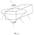
ミューオンの源及び鉛直から離されるコサインの二乗の減少により、実質的に、鉛直に平行化されたビームが提供される。計測は、図示の例では略円錐である、検出器1の視野7内の材料本体及び任意の放射性材料の全体としての密度に関する情報を供する。視野7は、ISO貨物容器5の全長を含んでいないので、ISO貨物容器5を検出器1に対して移動させることは、ISO貨物容器5及びその内容物の異なる部分X,Y,Zに関する潜在的に異なる密度情報を提供する。
The reduction of the cosine square away from the muon source and the vertical provides a substantially vertically collimated beam. The measurement provides information on the overall density of the material body and any radioactive material in the field of view 7 of the
本発明の第2の形態では、図2に示すように、測定位置下方の検出器1は、同一種類の第2の検出器9により補足される。この場合、2つの検出器間で同時に起こるミューオンが考慮される。即ち、同一のミューオンが検出器1を通過し次いで検出器9を通過する瞬間である。双方の検出器を介する通路のためのこの要求は、そこからミューオンが来ていなければならない視野を制約する。この場合、矩形断面のピラミッド型の視野11は、使用されるスラブ型検出器1,9に起因して生ずる。この場合、ミューオン信号は、エネルギと同時性の双方に起因してガンマから識別可能である。
In the second embodiment of the present invention, as shown in FIG. 2, the
結果としてのより密な視野11は、より多くの位置特有の密度測定を成すことを可能とする。 The resulting denser field of view 11 makes it possible to make more position-specific density measurements.
本発明の第1の形態に関して、ISO貨物容器5の束レベルに対する影響の前の束レベルは、検出器6を並列に用いることにより若しくは検出器1,9を用いてISO貨物容器5のあるときと無いときに測定を行うことにより、計測されることができる。
With respect to the first aspect of the present invention, the bundle level before the effect on the bundle level of the
図3に示す本発明の第3の形態では、検出器1は、考慮されるべきISO貨物容器5及び内容物、材料本体の下方に配置され、同等の種類の更なる検出器15は、ISO貨物容器5の上方に設けられる。同様に、ミューオンと更なる検出器15との間の相互作用は、信号を生み、同一のミューオンが当該検出器1を通過したときに検出器1にも信号が生じ、同時の検出が生じる。2つの検出器1,15からの信号のタイミングは、同一のミューオンと相互作用する双方の検出器1,15から生じたと看做されるこれらの信号を確立するものと考えられる。2つの相互作用の低い方のエネルギに対するエネルギの減少は、2つの検出器1,15の間の経路中にある材料本体及び/又は放射性材料の影響によるものと看做される。エネルギの減少が大きいほど、密度が大きく、従って、遮蔽及び/又は減衰作用が大きい。
In the third form of the invention shown in FIG. 3, the
動作の同一の原理は、3つの検出器1a,1b,1c及び3つの更なる検出器15a,15b,15cのそれぞれに対して適用する。検出器15a及び1b等のような、種々の組み合わせ間での更なる同時性も考慮されることができ、これにより全体で9つの計数チャンネルが付与される。この数の検出器は、図示の目的だけであり、ISO貨物容器5の全長に沿って配置されたより大きな数の及び/又は同様のセットの検出器が可能である。多数の検出器1及び多数の更なる検出器15をかかる構成で使用することは、ISO貨物容器のセグメント20の良好な有効範囲(カバレージ)が、検出器組み合わせに対する重なり合う視野に起因して、達成され、セグメントに対する特有の密度を計測することができ、更なるセグメント特有の更なる計測が可能であることを意味する。
The same principle of operation applies to each of the three detectors 1a, 1b, 1c and the three
更なる検出器15は、また、ISO貨物容器5の前の束経路内の位置に起因してISO貨物容器5に遭遇する前に束を検出する機能を果たすことができる。
The further detector 15 can also serve to detect the bundle before encountering the
多数の検出器1及び更なる検出器15の設置は、また、セグメント20により密度部分布に関する情報を得ることができることを意味する。これは、異なる組み合わせに対してそれらの視野の幾何学形状と連携して観測される差異を考慮することによって成されることができる。例示される6つの検出器の場合、セグメントに対する潜在的に異なる密度の3×3ピクセルの表示が提供されうる。より大きな数の検出器1及び更なる検出器15は、セグメント内でのより大きな分解能を可能とするだろう。
The installation of a large number of
好ましくは、検出器1は、ISO貨物容器5の底部に非常に近くに搭載されることができ、これにより、下方の深さ空間の必要性を無くす。側方に配置される検出器は、あいまいさを低減し若しくは更なる分解能を付与するために使用されることができる。
Preferably, the
当然ながら、かかる配置の検出器1は、上述の例と同様の態様で、更なる検出器15からの切り離された考慮で使用されうる。
Of course, the
上述の説明では、我々は、材料本体自体からであれ及び/又はその中の放射性材料からであれ、材料本体内で遭遇する材料の密度に関する情報を得るためにミューオンの使用に注目してきた。随伴するミューオン束は、ミューオン束レベルの約35から40%で電子の束である。かかる電子は、特に比較的高い密度の材料のような、相当な厚さの材料を通過するのには不十分な貫通性であるが、より薄い材料及び/又は小さい密度の材料に関する情報を与えるために同様の態様で使用されることができる。一般的に、電子は、15cmの厚さの鉛(密度167g・cm−1)により全体的に遮蔽されるだろう。 In the above description we have focused on the use of muons to obtain information regarding the density of materials encountered within the material body, whether from the material body itself and / or from the radioactive material therein. The accompanying muon bundle is a bundle of electrons at about 35 to 40% of the muon bundle level. Such electrons are insufficiently penetrating to pass through a substantial thickness of material, such as a relatively high density material, but provide information about thinner and / or lower density materials. Can be used in a similar manner. In general, electrons will be totally shielded by 15 cm thick lead (density 167 g · cm −1 ).
図1,2及び3を参照して上述した本発明の実施例では、アプローチは、ミューオン若しくは電子に対する計数率に対する材料本体の影響の測定値に依存してきた。計数率は、ミューオン若しくは電子の検出若しくはそれらに伴う同時性の検出に関連する。これは、次いで、測定が実行される対象のセグメント内の材料本体の密度の直接の測定値を与えるために使用される。次の実施例では、代替的なアプローチが取られる。 In the embodiments of the invention described above with reference to FIGS. 1, 2 and 3, the approach has relied on measurements of the influence of the material body on the count rate for muons or electrons. The count rate is related to the detection of muons or electrons or the coincidence detection associated therewith. This is then used to give a direct measure of the density of the body of material in the segment for which the measurement is performed. In the following example, an alternative approach is taken.
図4に示すように、本システムの一般的な構成は、上述と同様である。ISO貨物容器5は、測定位置3内に設けられる。4つの検出器20が測定位置3の上方に設けられ、更なる4つの検出器22は、測定値3の下方に設けられる。
As shown in FIG. 4, the general configuration of this system is the same as described above. The
検出器20,22は、ISO貨物容器5に理に適う範囲でできるだけ近くに配置される。同様の構成は、広範な容器種類に対して使用されることができる。ISO貨物容器の状況では、1/3.1/2,2/3及び3/4の高さの容器は、考慮されることができる。検出器20の上列の位置は、下側の検出器22と上側の検出器20の間の最小の離間距離を達成するように、減少した高さの容器に合わせて下方に調整されてもよい。
The
検出器20,22は、通常、互いに同一の種類、形状及びサイズである。検出器20,22のそれぞれ1つは、実際には、出力が1つとして扱われる一連の小型の検出器であってよい。プラスティックシンチレータが使用され、それぞれ光倍増器若しくはその類に接続され、光倍増器からの出力を高速の選別器に供給する。高速の選別器は、宇宙線派生計数、ミューオン等とガンマ線との間を識別するために用いられる。高速の選別器からの出力は、コンピューター制御ハードウェア若しくはソフトウェアにより動作される計数ステップに供給される。
The
ISO貨物容器5の正味重量は、本発明のこの実施例に対して必要とされる。正味重量は、放射性測定前若しくは後又はその間にISO貨物容器が設けられる重量ステーションにて取得されてもよい。重量ステーションは、測定位置3にあってもよい。
The net weight of the
ISO貨物容器5の正味重量は、後に処理で使用され、観測された重量として考慮される。
The net weight of the
ISO貨物容器5が測定位置3に導かれる前に、ミューオン若しくは電子の背景計数の測定は、同時性の検出器20,22の性能を確かめるために実行される。更なるかかる測定は、ISO貨物容器5が測定位置3から出発した後にもなされる。
Before the
測定方法中、10から16つの測定値は、ISO貨物容器5の全長に沿った異なる位置で取られて、ISO貨物容器5を10から16つのセグメントに実質的に分割するようにする。かかる数は、ISO貨物容器5の6mの長さを効率的に考慮している。ISO貨物容器5は、各測定中は固定状態である。
During the measurement method, 10 to 16 measurements are taken at different positions along the entire length of the
各測定中、測定位置3の上方に設けられる検出器20A,20B,20C,20Dを参照し、測定位置3の下方に設けられる検出器22A,22B,22C,22Dを参照して、次の計数が確立される。
20A信号計数;
20B信号計数;
20C信号計数;
20D信号計数;
22A信号計数;
22B信号計数;
22C信号計数;
22D信号計数;
20Aと22Aの同時計数;
20Aと22Bの同時計数;
20Aと22Cの同時計数;
20Aと22Dの同時計数;
20Bと22Aの同時計数;
20Bと22Bの同時計数;
20Bと22Cの同時計数;
20Bと22Dの同時計数;
20Cと22Aの同時計数;
20Cと22Bの同時計数;
20Cと22Cの同時計数;
20Cと22Dの同時計数;
20Dと22Aの同時計数;
20Dと22Bの同時計数;
20Dと22Cの同時計数;及び
20Dと22Dの同時計数。
During each measurement, the
20A signal counting;
20B signal counting;
20C signal counting;
20D signal counting;
22A signal counting;
22B signal counting;
22C signal counting;
22D signal counting;
Simultaneous counting of 20A and 22A;
Simultaneous counting of 20A and 22B;
Simultaneous counting of 20A and 22C;
Simultaneous counting of 20A and 22D;
Simultaneous counting of 20B and 22A;
Simultaneous counting of 20B and 22B;
Simultaneous counting of 20B and 22C;
Simultaneous counting of 20B and 22D;
Simultaneous counting of 20C and 22A;
Simultaneous counting of 20C and 22B;
Simultaneous counting of 20C and 22C;
Simultaneous counting of 20C and 22D;
Simultaneous counting of 20D and 22A;
Simultaneous counting of 20D and 22B;
Simultaneous counting of 20D and 22C; and simultaneous counting of 20D and 22D.
これらの測定値の全ては、後の取り出し及び処理のために記憶される。 All of these measurements are stored for later retrieval and processing.
続く処理は、各測定時に16つの同時計数のそれぞれをとり、適切な上側の検出器20に対する信号計数の分数として表現するが、連携して考慮される対の検出器の幾何的な配置の影響に対して補正された信号計数率が用いられる。従って、20A及び22Aに対する同時性は、検出器対20A及び22Aの幾何的配置に対して補正された信号計数率による20Aの信号計数の分数として表現され、20A及び22Bに対する同時性は、検出器対20A及び22Bの幾何的配置に対して補正された信号計数率による20Aの信号計数の分数として表現され、20D及び22Aに対する同時性は、検出器対20D及び22Aの幾何的配置に対して補正された信号計数率による20Dの信号計数の分数として表現され、以下同様である。各対の場合の同時計数は、当該対に対する補正された信号計数により除算される。
Subsequent processing takes each of the 16 coincidence counts at each measurement and expresses it as a fraction of the signal count for the appropriate
幾何的配置に対する補正は、材料本体の不在状態で、幾何的配置に起因して、上側の検出器を通過するが下側の検出器を通過しないだろう粒子のフラクションを考慮する補正である。基本的には、このフラクションは、検出器20A及び22Dのような、オフセットした対の検出器に対しては、検出器20A及び22Aのような、互いに鉛直方向に一直線となる対の検出器に対してよりも、高くなる。
The correction to the geometry is a correction that takes into account the fraction of particles that would pass through the upper detector but not through the lower detector due to the geometry in the absence of the body of material. Basically, this fraction is applied to a pair of detectors that are vertically aligned with each other, such as
このフラクションは、幾何的配置の校正を介して取得される。各検出器の対に対して、幾何的配置の校正は、材料本体の不在状態で、材料本体の測定に対してと同一の幾何的配置の検出器により測定を実行することによって、取得される。好ましくは、フラクションを計測するための測定は、十分な期間に亘って、例えば1日若しくは2日に亘って実行され、各対に対してフラクションの満足の行く良好な測定を与えるようにする。対に対する結果は、実際のサンプルの測定での使用のために値若しくは式又はルックアップテーブルとして、記憶されてもよい。 This fraction is obtained through calibration of the geometry. For each detector pair, the geometry calibration is obtained by performing the measurement with the same geometry detector for the measurement of the material body in the absence of the material body. . Preferably, the measurement for measuring the fraction is performed over a sufficient period of time, for example over one or two days, so as to give a satisfactory measurement of the fraction for each pair. Results for pairs may be stored as values or expressions or look-up tables for use in actual sample measurements.
基本的には、補正は、ミューオンの束Nが、幾何的配置のみに単に起因して、上側若しくは第2の検出器20を通過するが、束Cのみが下側若しくは第1の検出器22に到達するであろうことを言う。以下で詳説する如く、材料本体が存在する状態では、下側若しくは第1の検出器22に到達するであろう束は、材料本体に更に起因して束Lへと減少する。特定の対に対する補正の結果として、同時計数に対する幾何的配置の影響は取り除かれる。
Basically, the correction is that the muon bundle N passes through the upper or
上記の例において、この処理は、材料本体の当該セグメントの測定値に対して16つの補正されたフラクションを生む。 In the example above, this process yields 16 corrected fractions for the measurement of that segment of the material body.
処理の次の段階では、材料本体の幾何的配置の影響が考慮される。基本的には、材料本体の存在に起因して、上側の検出器を通過するが下側の検出器を通過しないだろう粒子のフラクションが考慮される。これは、幾何的配置に起因した影響は既に除去されている下側の検出器計数に影響する他の因子である。基本的には、この影響は、低い密度の材料本体よりも高い密度の材料本体の方が高いだろう。 In the next stage of processing, the influence of the geometry of the material body is taken into account. Basically, due to the presence of the material body, the fraction of particles that will pass through the upper detector but will not pass through the lower detector is taken into account. This is another factor that affects the lower detector count, where the effects due to geometry are already removed. Basically, this effect will be higher for a high density material body than for a low density material body.
影響の考慮は、面密度校正データを参照することにより得られる。面密度校正データは、ルックアップテーブル若しくは公式のいずれかで用いられる。面密度校正データは、モデル化から生成し、若しくは、より好ましくは、異なる面密度によるフラクション計数に対する吸収剤の影響を計測するために、広範な異なる吸収材料の実際の測定から生成する。校正データの一例は、図5に示され、面密度に応じたフラクション計数率のプロットである。上側と下側の検出器の間の離間距離を最小にすることは、高い密度値で面密度の正確な解明を可能とする計数率を得る上で非常に重要である。 Consideration of influence can be obtained by referring to surface density calibration data. The surface density calibration data is used in either a lookup table or a formula. The areal density calibration data is generated from modeling or, more preferably, from actual measurements of a wide variety of different absorbent materials to measure the effect of the absorbent on fraction counts due to different areal densities. An example of the calibration data is shown in FIG. 5 and is a plot of the fraction count rate according to the surface density. Minimizing the separation between the upper and lower detectors is very important in obtaining a count rate that allows accurate resolution of the surface density at high density values.
基本的には、本アプローチでは、上側の検出器での束がNであり、幾何的配置及び材料本体の影響は、下側の検出器で束Lに減少させる。 Basically, in this approach, the bundle at the upper detector is N, and the geometrical and material body effects are reduced to bundle L at the lower detector.
16つのフラクションの値のそれぞれは、例えば図5に示すような試験的に得られた値及び校正データを用いて面密度値に変換される。 Each of the 16 fraction values is converted into an areal density value using, for example, a test value and calibration data as shown in FIG.
セグメントに対する16つの面密度は、当該セグメントに対する結合面密度を与えるために結合される。結合処理は、好ましくは、重み付けされる。種々の係数は、16つの面密度値のそれぞれに対する重みを決定するために使用されることができる。係数は、当該対の検出器に対するISO貨物容器5を通る経路長、検出器の鉛直方向の離間距離、各検出器対によりサンプリングされた実効容積、当該検出器対に対する計数率の精度を含んでよい。
The 16 areal densities for a segment are combined to give a bond areal density for that segment. The combining process is preferably weighted. Various factors can be used to determine the weight for each of the 16 areal density values. The coefficients include the path length through the
各セグメントに対するこの処理を繰り返すことによって、単一の結合された面密度値が各セグメントに対して得られる。 By repeating this process for each segment, a single combined areal density value is obtained for each segment.
これらの結合された面密度値は、次いで、ISO貨物容器の計算重量を生成するためにISO貨物容器5の寸法と共に使用されることができる。次いで、計算重量は、観測重量に対して考慮され、2つの間の変動は、各セグメントに対する結合面密度値の値を正規化するために使用される。各セグメントに対する正規化された結合面密度値は、結果として生成される。
These combined areal density values can then be used with the dimensions of the
セグメントに対する正規化された結合面密度値は、次いで、補正されたガンマ放出物の測定値を与えるために当該セグメントに対する測定されたガンマ放出物の測定値を補正するために使用される。この値は、次いで、ISO貨物容器5の更なる考慮で使用される。
The normalized bond surface density value for the segment is then used to correct the measured gamma emission measurement for that segment to provide a corrected gamma emission measurement. This value is then used for further consideration of the
幾つかの例では、結果は、ISO貨物容器5が特定の更なる考慮を必要とすることを示唆する。かかる状況の例は、1つ以上のセグメントに対する面密度が所定の範囲外である及び/又は上限値を超えている及び/又は下限値を下回っている場合でありうる。
In some examples, the results suggest that the
ISO貨物容器5が満載で無い場合、計算重量若しくは観測重量が調整されてもよい。調整は、材料本体が実際に充填されているISO貨物容器5の割合を反映するだろう。これは、材料本体の物理的な検査から、及び/又は、満載レベルよりも下方に位置するときに検出が遮蔽され満載レベルよりも上方の位置が検出されたときに検出される送信源により判断されうる。
If the
次の章は、アプローチの特性により改善されたレベルで考慮されることができる、かかるアプローチ及び態様を取ることにより存在する誤りに関する。 The next section relates to errors that exist by taking such approaches and aspects that can be considered at an improved level due to the characteristics of the approach.
第1の選択肢において、材料本体が存在しない状態での対の検出器20A及び22Aの同時計数を、材料本体が存在する状態での対20A及び22Aの同時計数に対して考慮することは可能である。しかし、双方の計数率は、直交で加わるそれらに関連付けられた同様の不確定さを有する。更に、気圧変化及び太陽の活動変化(その間ミューオン束が減少するフォアブシュ事象に関連する)も誤りを引き起こし、別々に考慮される必要があるだろう。
In the first option, the coincidence of the pair of
本発明の好ましいアプローチでは、代替的な考慮がなされる。基本的には、本アプローチは、ミューオンの束Nが、上側若しくは第2の検出器20を通過するが、上側と下側の検出器間の介入プロセスに起因して、減少された束Lのみが下側の検出器22に到達する可能性があることを言う。プロセスの確率は、Pと表すことができる。確率は、2つの損失機構を有する。これらは、使用される検出器の対の幾何的配置と、使用される対の検出器間にある材料本体の吸収に起因する。
In the preferred approach of the present invention, alternative considerations are made. Basically, this approach is that muon bundle N passes through the upper or
上側の検出器20は、問合せ束Nを測定し、従って、これは、正確に知られる。問合せ束Nは、下側の検出器により検出される同時計数により測定される送信束Lに変化される。同時性は、損失プロセスの影響及び問合せ束Nに対するその確率Pを測定し、これは、同一性は送信束のサンプルである第1の選択肢と比較する。
The
好ましいアプローチを適用すると、密度計算は、次のとおりである。 Applying the preferred approach, the density calculation is as follows:
Claims (35)
前記放射性材料により生成される放出を直接的又は間接的に求めることにより前記材料本体内の放射性材料の量の予備的な測定値を求めるステップと、
前記材料本体を通過していないミューオンにより生成された電子及び/又はミューオンを検出して第1の値を与えるステップと、
前記材料本体を通過したミューオンにより生成された電子及び/又はミューオンを検出して第2の値を与えるステップと、
前記第1及び第2の値を処理して、前記第1の値と校正係数の積により除算された前記第2の値の関数である密度表現の係数を与えるステップと、
前記材料本体の放射性材料の量の補正された測定値を得るために、前記材料本体内の放射性材料の量の予備的な測定値に前記係数を適用するステップとを含む、方法。 A method for determining the amount of radioactive material in a material body,
Determining a preliminary measurement of the amount of radioactive material in the material body by determining directly or indirectly the emission produced by the radioactive material ;
Detecting electrons and / or muons generated by muons not passing through the material body to provide a first value;
Detecting electrons and / or muons generated by the muons that have passed through the material body to provide a second value;
Processing the first and second values to provide a density representation coefficient that is a function of the second value divided by the product of the first value and a calibration coefficient ;
Wherein in order to obtain a corrected measurement of the amount of radioactive materials of the body, and a step of applying said coefficients to the preliminary measurement of the amount of radioactive material in the material body, the method.
前記材料本体を通過したミューオンにより生成された電子及び/又はミューオンを検出して第2の値を与えるステップは、1つ以上の第2の検出器を使用し、
前記第1の値及び第2の値に寄与するミューオン及び/又は電子は、同一のミューオン及び/又は電子が2つの検出器を通過するときの同時計数値の測定値を付与するために使用され、前記同時計数値の前記第1の値に対する比は、前記係数の算出時に考慮される、先行する請求項のうちのいずれか1項に記載の方法。 Detecting electrons and / or muons generated by muons that have not passed through the material body to provide a first value comprises one or more first detectors and, if present, one or more. Using a third detector of
Detecting the electrons and / or muons generated by the muons that have passed through the material body to provide a second value comprises using one or more second detectors;
The muons and / or electrons contributing to the first and second values are used to give a measurement of the same clock value when the same muon and / or electrons pass through two detectors. The method according to any one of the preceding claims, wherein a ratio of the clock value to the first value is taken into account when calculating the coefficient.
前記放射性材料により生成される放出を直接的又は間接的に求めることにより前記材料本体内の放射性材料の量の予備的な測定値を提供する1つ以上の検出器と、
測定位置の上方に設けられ、前記材料本体を通過していない大気源からの1種類以上の粒子を検出して第1の値を与える1つ以上の第1の検出器と、
測定位置の下方に設けられ、前記材料本体を通過した大気源からの1種類以上の粒子を検出して第2の値を与える1つ以上の第2の検出器と、
前記第1及び第2の値を処理して、前記第1の値と校正係数の積により除算された前記第2の値の関数である密度表現の係数を与えると共に、前記材料本体の放射性材料の量の補正された測定値を得るために、前記材料本体内の放射性材料の量の予備的な測定値に前記係数を適用するプロセッサとを含む、装置。 A device for determining the amount of radioactive material in a material body,
One or more detectors providing a preliminary measurement of the amount of radioactive material in the material body by directly or indirectly determining the emission produced by the radioactive material ;
Provided above the measurement position, and one or more of the first detector providing a first value to detect one or more particles from the atmosphere source not through the body of material,
Provided below the measurement position, and one or more second detector providing a second value to detect one or more particles from the atmosphere source which has passed through the body of material,
Processing the first and second values to provide a coefficient of density representation that is a function of the second value divided by the product of the first value and a calibration factor, and the radioactive material of the material body And a processor that applies the coefficient to a preliminary measurement of the amount of radioactive material in the material body to obtain a corrected measurement of the amount of the material .
前記放射性材料により生成される放出を直接的又は間接的に求めることにより前記材料本体内の放射性材料の量の予備的な測定値を求めるステップと、
第2の検出器を用いて、前記材料本体を通過していない大気源からの1種類以上の粒子を検出して第1の値を与えるステップと、
第1の検出器を用いて、前記材料本体及び前記第2の検出器を通過した大気源からの1種類以上の粒子を検出して第2の値を与えるステップと、
前記第1及び第2の値を処理して、前記第1の値と校正係数の積により除算された前記第2の値の関数である密度表現の係数を与えるステップと、
前記材料本体の放射性材料の量の補正された測定値を得るために、前記係数を用いて前記材料本体内の放射性材料の量の測定値を補正するステップとを含み、
前記係数の誤りを確立することは、
前記第1の値が正確に測定されており、前記校正係数が正確に知られており、且つ、前記第2の値が確率により乗算された前記第1の値であると看做すことを含み、前記確率は、前記第2の値及び前記第1の値に寄与する粒子の確率である、方法。 Establishing an error in the coefficients used in the method of correcting the measurement of radioactive material in the material body,
Determining a preliminary measurement of the amount of radioactive material in the material body by determining directly or indirectly the emission produced by the radioactive material ;
Using a second detector to detect one or more particles from an atmospheric source that has not passed through the material body to provide a first value;
Using a first detector to detect one or more particles from an atmospheric source that has passed through the material body and the second detector to provide a second value;
Processing the first and second values to provide a density representation coefficient that is a function of the second value divided by the product of the first value and a calibration coefficient;
To obtain the corrected measured value of the amount of radioactive material in the material body, and a step of correcting the measurement of the amount of radioactive material within the body of material using said coefficients,
Establishing an error in the coefficient is
Assume that the first value is accurately measured, the calibration factor is accurately known, and the second value is the first value multiplied by probability. And the probability is a probability of particles contributing to the second value and the first value.
Applications Claiming Priority (3)
| Application Number | Priority Date | Filing Date | Title |
|---|---|---|---|
| GBGB0605741.8A GB0605741D0 (en) | 2006-03-22 | 2006-03-22 | Improvements in and relating to detection |
| GB0605741.8 | 2006-03-22 | ||
| PCT/GB2007/001026 WO2007107765A1 (en) | 2006-03-22 | 2007-03-21 | Correction of a radioactivity measurement using particles from atmospheric source |
Publications (2)
| Publication Number | Publication Date |
|---|---|
| JP2009530630A JP2009530630A (en) | 2009-08-27 |
| JP5204089B2 true JP5204089B2 (en) | 2013-06-05 |
Family
ID=36383959
Family Applications (1)
| Application Number | Title | Priority Date | Filing Date |
|---|---|---|---|
| JP2009500926A Expired - Fee Related JP5204089B2 (en) | 2006-03-22 | 2007-03-21 | Correction of radioactivity measurements using particles from atmospheric sources |
Country Status (5)
| Country | Link |
|---|---|
| US (1) | US8275567B2 (en) |
| EP (1) | EP1994430B1 (en) |
| JP (1) | JP5204089B2 (en) |
| GB (1) | GB0605741D0 (en) |
| WO (1) | WO2007107765A1 (en) |
Families Citing this family (16)
| Publication number | Priority date | Publication date | Assignee | Title |
|---|---|---|---|---|
| JP2008530581A (en) | 2005-02-17 | 2008-08-07 | トライアンフ,オペレーティング アズ ア ジョイント ヴェンチャー バイ ザ ガバナーズ オブ ザ ユニバーシティ オブ アルバータ,ザ ユニバーシティ オブ ブリティッシュ コロンビア,カールトン | Geological tomography using cosmic rays |
| US7531791B2 (en) | 2005-02-17 | 2009-05-12 | Advanced Applied Physics Solutions, Inc. | Geological tomography using cosmic rays |
| GB0605741D0 (en) | 2006-03-22 | 2006-05-03 | Bil Solutions Ltd | Improvements in and relating to detection |
| AU2009285682B2 (en) * | 2008-08-27 | 2015-03-12 | Decision Sciences International Corporation | Imaging based on cosmic-ray produced charged particles |
| GB0817703D0 (en) * | 2008-09-26 | 2008-11-05 | Vt Nuclear Services Ltd | Improvements in and relating to assaying of waste |
| CN103460075B (en) * | 2010-11-29 | 2019-05-31 | 前视红外探测公司 | The method and database of nucleic for identification |
| GB201020502D0 (en) | 2010-12-03 | 2011-01-19 | Babcock Nuclear Ltd | Improvements in and relating to processing |
| JP2013217811A (en) * | 2012-04-10 | 2013-10-24 | Toshiba Corp | Internal state observation method and internal state observation device |
| EP2992316B1 (en) | 2013-04-29 | 2018-04-18 | Decision Sciences International Corporation | Muon detector array stations |
| JP2015148448A (en) * | 2014-02-04 | 2015-08-20 | キヤノン株式会社 | Charged particle detection device, and gamma camera |
| US9915626B2 (en) * | 2014-02-26 | 2018-03-13 | Decision Sciences International Corporation | Discrimination of low-atomic weight materials using scattering and stopping of cosmic-ray electrons and muons |
| JP6522299B2 (en) * | 2014-04-01 | 2019-05-29 | ロス アラモス ナショナル セキュリティ,エルエルシー | Non-invasive in-situ imaging method and apparatus inside a nuclear reactor |
| WO2016025409A1 (en) | 2014-08-11 | 2016-02-18 | Decision Sciences International Corporation | Material discrimination using scattering and stopping of muons and electrons |
| US10451745B1 (en) * | 2014-12-11 | 2019-10-22 | National Technology & Engineering Solutions Of Sandia, Llc | Muon detectors, systems and methods |
| CN108572387B (en) * | 2017-03-07 | 2023-07-14 | 中国辐射防护研究院 | Calibration method of body source measurement detector |
| US11010852B2 (en) * | 2017-06-30 | 2021-05-18 | Lantern Unmanned Autonomous Systems, Llc | Unmanned autonomous container inspection |
Family Cites Families (13)
| Publication number | Priority date | Publication date | Assignee | Title |
|---|---|---|---|---|
| FR1147321A (en) * | 1956-04-09 | 1957-11-21 | Commissariat Energie Atomique | New fission neutron detector |
| JPH08261741A (en) * | 1995-03-23 | 1996-10-11 | Sumitomo Metal Ind Ltd | Measuring method for blast furnace refractory thickness |
| US5594250A (en) | 1995-04-03 | 1997-01-14 | Condreva; Kenneth J. | Method for detecting water equivalent of snow using secondary cosmic gamma radiation |
| JP2000155101A (en) * | 1998-11-20 | 2000-06-06 | Yuasa Corp | Method and apparatus for quantifying element |
| DE60020214T2 (en) * | 1999-01-11 | 2006-03-23 | British Nuclear Fuels Plc, Warrington | DEVICE AND METHOD FOR EXAMINING RADIOACTIVE RADIATION SOURCES IN A SAMPLE |
| US6509563B1 (en) * | 1999-07-27 | 2003-01-21 | Canberra Industries, Inc. | Method for reduction in the interference of cosmic ray-induced neutron events in passive neutron coincidence and multiplicity counting |
| US6420712B1 (en) * | 2000-07-03 | 2002-07-16 | The Regents Of The University Of California | Cosmic ray neutron background reduction using localized coincidence veto neutron counting |
| US7015475B2 (en) | 2003-05-06 | 2006-03-21 | The Trustees Of Columbia University In The City Of New York | Method and apparatus for material identification using characteristic radiative emissions |
| CN100420937C (en) * | 2003-09-18 | 2008-09-24 | 清华大学 | Method for monitoring positioning of vehicle radioactive substance and its device |
| US7756237B2 (en) * | 2004-10-19 | 2010-07-13 | Lawrence Livermore National Security, Llc | Absolute nuclear material assay |
| CA2511593A1 (en) * | 2004-10-18 | 2006-04-18 | Hugh Robert Andrews | A method and apparatus for detection of radioactive materials |
| JP4853803B2 (en) * | 2005-10-31 | 2012-01-11 | 新日本製鐵株式会社 | Blast furnace bottom management method |
| GB0605741D0 (en) | 2006-03-22 | 2006-05-03 | Bil Solutions Ltd | Improvements in and relating to detection |
-
2006
- 2006-03-22 GB GBGB0605741.8A patent/GB0605741D0/en not_active Ceased
-
2007
- 2007-03-21 EP EP07732099A patent/EP1994430B1/en not_active Not-in-force
- 2007-03-21 JP JP2009500926A patent/JP5204089B2/en not_active Expired - Fee Related
- 2007-03-21 US US12/281,970 patent/US8275567B2/en active Active
- 2007-03-21 WO PCT/GB2007/001026 patent/WO2007107765A1/en active Application Filing
Also Published As
| Publication number | Publication date |
|---|---|
| EP1994430A1 (en) | 2008-11-26 |
| JP2009530630A (en) | 2009-08-27 |
| US8275567B2 (en) | 2012-09-25 |
| GB0605741D0 (en) | 2006-05-03 |
| US20100010764A1 (en) | 2010-01-14 |
| EP1994430B1 (en) | 2012-12-26 |
| WO2007107765A1 (en) | 2007-09-27 |
Similar Documents
| Publication | Publication Date | Title |
|---|---|---|
| JP5204089B2 (en) | Correction of radioactivity measurements using particles from atmospheric sources | |
| CN101833116B (en) | Special nuclear material examination by neutrons and delayed neutrons | |
| Priedhorsky et al. | Detection of high-Z objects using multiple scattering of cosmic ray muons | |
| US9841530B2 (en) | Material discrimination using scattering and stopping of muons and electrons | |
| CN102084270B (en) | Scanning system | |
| US7286638B2 (en) | Methods and systems for determining the average atomic number and mass of materials | |
| US9915626B2 (en) | Discrimination of low-atomic weight materials using scattering and stopping of cosmic-ray electrons and muons | |
| US9212905B2 (en) | Method and system for determining radiation shielding thickness and gamma-ray energy | |
| US20120046867A1 (en) | Portable System for Analyzing and Determining Elemental Composition of Rock Samples | |
| CN105849536B (en) | Spectral analysis using spectral deconvolution | |
| CN101606083A (en) | Detection of particles and application thereof aspect safety and portal monitoring | |
| US7902519B2 (en) | Monitoring | |
| WO2017012562A1 (en) | Method and apparatus for estimating weight of inspected object in safety inspection system | |
| WO2016080610A1 (en) | Method and apparatus for distinguishing radionuclide by using plastic scintillator | |
| CN101019042B (en) | Object examination by dual energy radiation scanning and delayed neutron detection | |
| US20160097729A1 (en) | Charged particle tomography with improved momentum estimation | |
| US10215717B2 (en) | Detection of an object within a volume of interest | |
| US10175382B2 (en) | Identification of materials | |
| Mosorov et al. | Monte Carlo simulation for multi-channel gamma-ray process tomography | |
| JP6139391B2 (en) | Radioactivity inspection apparatus and method | |
| McNabb et al. | Uncertainty budget and efficiency analysis for the 239Pu (n, 2ny) partial reaction cross-section measurements | |
| EP1491915A1 (en) | Method and system for gamma ray positron imaging | |
| Kalinnikov et al. | Research of the ECAL calorimeter used in the COMET experiment | |
| Mihailescu et al. | Measurement of high-resolution neutron inelastic scattering cross sections for 52Cr from threshold up to 18 MeV | |
| Jordan et al. | Automated UF6 Cylinder Enrichment Assay: Status of the Hybrid Enrichment Verification Array (HEVA) Project: POTAS Phase II |
Legal Events
| Date | Code | Title | Description |
|---|---|---|---|
| A621 | Written request for application examination |
Free format text: JAPANESE INTERMEDIATE CODE: A621 Effective date: 20100217 |
|
| A131 | Notification of reasons for refusal |
Free format text: JAPANESE INTERMEDIATE CODE: A131 Effective date: 20120104 |
|
| A601 | Written request for extension of time |
Free format text: JAPANESE INTERMEDIATE CODE: A601 Effective date: 20120402 |
|
| A602 | Written permission of extension of time |
Free format text: JAPANESE INTERMEDIATE CODE: A602 Effective date: 20120409 |
|
| A601 | Written request for extension of time |
Free format text: JAPANESE INTERMEDIATE CODE: A601 Effective date: 20120502 |
|
| A602 | Written permission of extension of time |
Free format text: JAPANESE INTERMEDIATE CODE: A602 Effective date: 20120511 |
|
| A521 | Request for written amendment filed |
Free format text: JAPANESE INTERMEDIATE CODE: A523 Effective date: 20120531 |
|
| TRDD | Decision of grant or rejection written | ||
| A01 | Written decision to grant a patent or to grant a registration (utility model) |
Free format text: JAPANESE INTERMEDIATE CODE: A01 Effective date: 20130115 |
|
| A61 | First payment of annual fees (during grant procedure) |
Free format text: JAPANESE INTERMEDIATE CODE: A61 Effective date: 20130214 |
|
| R150 | Certificate of patent or registration of utility model |
Ref document number: 5204089 Country of ref document: JP Free format text: JAPANESE INTERMEDIATE CODE: R150 Free format text: JAPANESE INTERMEDIATE CODE: R150 |
|
| FPAY | Renewal fee payment (event date is renewal date of database) |
Free format text: PAYMENT UNTIL: 20160222 Year of fee payment: 3 |
|
| R250 | Receipt of annual fees |
Free format text: JAPANESE INTERMEDIATE CODE: R250 |
|
| R250 | Receipt of annual fees |
Free format text: JAPANESE INTERMEDIATE CODE: R250 |
|
| R250 | Receipt of annual fees |
Free format text: JAPANESE INTERMEDIATE CODE: R250 |
|
| R250 | Receipt of annual fees |
Free format text: JAPANESE INTERMEDIATE CODE: R250 |
|
| R250 | Receipt of annual fees |
Free format text: JAPANESE INTERMEDIATE CODE: R250 |
|
| LAPS | Cancellation because of no payment of annual fees |