JP5202121B2 - Cylindrical bracket for cylindrical vibration isolator - Google Patents
Cylindrical bracket for cylindrical vibration isolator Download PDFInfo
- Publication number
- JP5202121B2 JP5202121B2 JP2008154737A JP2008154737A JP5202121B2 JP 5202121 B2 JP5202121 B2 JP 5202121B2 JP 2008154737 A JP2008154737 A JP 2008154737A JP 2008154737 A JP2008154737 A JP 2008154737A JP 5202121 B2 JP5202121 B2 JP 5202121B2
- Authority
- JP
- Japan
- Prior art keywords
- cylindrical
- mounting leg
- divided
- divided body
- axial direction
- Prior art date
- Legal status (The legal status is an assumption and is not a legal conclusion. Google has not performed a legal analysis and makes no representation as to the accuracy of the status listed.)
- Expired - Fee Related
Links
Images


Description
この発明は、エンジンマウント等の筒型防振装置に用いられる筒型金具に関する。 The present invention relates to a cylindrical metal fitting used for a cylindrical vibration isolator such as an engine mount.
この種の筒型金具として、筒部の両端にフランジを一体に形成した形状になるように板材を深絞りしてプレス成形で形成することが知られている。また一端側にのみフランジを有する防振装置用の筒型金具を特殊な深絞りプレス成形するものがある(特許文献1参照)。
筒部の両端にフランジを有する形状に深絞りプレス成形すると、一般的な深絞りでは形成できるフランジの大きさに限界があり、フランジを利用して取付用脚部を溶接することができない。そのうえ筒部が薄くなるので剛性不足を招かないように成形前の板厚を大きなものにしなければならない。しかしこのようにすると不必要な部分まで厚肉化して全体の重量増加及びコストアップを招くことになる。
また、上記特許文献1による方法では比較的大きなフランジを形成できても手間がかかりかつ高価なものになるので量産に適さない。しかも一端側にしか形成できない。
そこで本願発明は、取付用金具を溶接できる程度に大きなフランジを両端に有するとともに、筒部の剛性を部分的に高くでき、しかも特殊な深絞りを要さずかつ安価で量産性のある筒型金具の提供を目的とする。
When deep drawing press molding into a shape having flanges at both ends of the cylindrical portion, there is a limit to the size of the flange that can be formed by general deep drawing, and the mounting leg cannot be welded using the flange. In addition, since the cylindrical portion becomes thin, the plate thickness before molding must be increased so as not to cause insufficient rigidity. However, if it does in this way, it will increase in thickness to an unnecessary part, and will cause the whole weight increase and cost increase.
Further, the method according to
Accordingly, the present invention has a cylindrical shape that has flanges large enough to weld the mounting bracket at both ends, can partially increase the rigidity of the cylindrical portion, and does not require a special deep drawing, and is inexpensive and mass-productive. The purpose is to provide metal fittings.
上記課題を解決するため筒型防振装置用筒型金具に係る請求項1の発明は、筒型防振装置に用いる筒型金具であって、筒部と、その軸方向両端の開口部に設けたフランジとを一体に設けた本体部と、この本体部へ溶接される取付脚とを備えた筒型防振装置用筒型金具において、
前記筒部を軸方向にて、第1の分割体と第2の分割体とに分割し、
第1及び第2の分割体はそれぞれ分割筒部と、その軸方向一端へ一体に形成されたフランジとを備え、
各分割筒部は、軸方向にて重なり合うラップ代を有し、
両ラップ代を軸方向にて重ね合わせて両分割筒部を内外に嵌合し、相互に一体化してなることを特徴とする。
In order to solve the above-mentioned problems, the invention according to
Dividing the cylindrical portion in the axial direction into a first divided body and a second divided body;
Each of the first and second divided bodies includes a divided cylindrical portion and a flange integrally formed at one end in the axial direction thereof.
Each divided tube portion has a lapping allowance overlapping in the axial direction,
Both laps are overlapped in the axial direction, and both divided cylinder parts are fitted inside and outside and integrated with each other.
また、前記第1の分割体と第2の分割体は肉厚が相対的に大小に異なることを特徴とする。 Further, the first divided member and the second split body is being different from the thickness is relatively large and small.
さらに、前記筒型防振装置は、軸方向を車両の前後方向に向けて配置され、前記肉厚が薄い方の分割体を減速側入力方向へ配置し、他方の肉厚がより厚い分割筒部を加速側入力方向へ配置したことを特徴とする。 Further , the cylindrical vibration isolator is arranged with the axial direction directed in the front-rear direction of the vehicle, the thinner divided body is arranged in the deceleration-side input direction, and the other thicker divided cylinder is arranged. The portion is arranged in the acceleration side input direction.
請求項2の発明は上記請求項1において、前記第1の分割体及び第2の分割体は、それぞれ一枚の板材を絞り加工してフランジと分割筒部を一体にして形成されるものであることを特徴とする。
Invention Oite to the
請求項3の発明は上記請求項1において、前記取付脚は、前記第1の分割体及び第2の分割体の各分割筒部における重なり合った部分を跨いで本体部へ溶接されることを特徴とする。 According to a third aspect of the present invention, in the first aspect, the mounting leg is welded to the main body portion across the overlapping portions of the divided cylindrical portions of the first divided body and the second divided body. And
請求項4の発明は上記請求項1において、前記取付脚は軸方向へ延出する第1の取付脚を備え、この第1の取付脚は垂直壁と水平壁を備え、一方フランジには縁部を直線状にすることにより垂直縁部と水平縁部を設け、垂直縁部を垂直壁へ重ね、水平縁部を水平壁へ重ね、これらの重なり合った部分を溶接することにより、第1の取付脚とフランジとを一体化したことを特徴とする。 According to a fourth aspect of the present invention, in the first aspect, the mounting leg includes a first mounting leg extending in the axial direction, and the first mounting leg includes a vertical wall and a horizontal wall, while the flange has an edge. By providing a vertical edge and a horizontal edge by straightening the part, overlapping the vertical edge to the vertical wall, overlapping the horizontal edge to the horizontal wall, and welding these overlapping parts, The mounting leg and the flange are integrated.
請求項5の発明は上記請求項1〜4のいずれかにおいて、前記取付脚は、軸方向へ延出する第1の取付脚と、筒部の外周部へ取付けられて径方向へ延出する第2の取付脚とを備えてそれぞれ別体に形成され、前記第1の分割体と第2の分割体とともに、これら計4部材を溶接で一体化して組み立てられることを特徴とする。 According to a fifth aspect of the present invention, in any one of the first to fourth aspects, the mounting leg is attached to the first mounting leg extending in the axial direction and the outer peripheral portion of the cylindrical portion and extends in the radial direction. It is characterized by being provided with a second mounting leg and separately formed, and together with the first divided body and the second divided body, these four members are integrally assembled by welding.
請求項6の発明は上記請求項1〜5のいずれかにおいて、前記取付脚は、軸方向へ延出する第1の取付脚と、筒部の外周部へ取付けられて径方向へ延出する第2の取付脚とを備え、これら第1及び第2の取付脚は一枚の板材からプレス成形により一体に形成されたものであることを特徴とする。 In a sixth aspect of the present invention, in any one of the first to fifth aspects, the mounting leg is attached to the first mounting leg extending in the axial direction and the outer peripheral portion of the cylindrical portion and extends in the radial direction. And a second mounting leg, wherein the first and second mounting legs are integrally formed from a single plate material by press molding.
請求項1によれば、筒部の軸方向にて第1の分割体と第2の分割体に分割し、各分割筒部に軸方向で重なり合うラップ代を設けたので、このラップ代を内外に重ねて一体化すれば、第1の分割体と第2の分割体を一体化した筒型金具を形成することができる。しかも、各分割筒部は筒部の軸方向で分割されるため、絞り量が少なくなり、特殊な深絞り技術を要さずに比較的大きなフランジを一体にしてプレス成形できる。また第1及び第2の分割体を結合一体化することで筒部の軸方向両端に比較的大きなフランジを有することになる。また、ラップ代における結合により、筒部剛性を部分的に高くでき、しかも他の部分の肉厚を大きくする必要がないので、筒部剛性の高さに比して全体を軽量化できる。しかも量産性に富みコストダウンできる。 According to the first aspect, since the first divided body and the second divided body are divided in the axial direction of the cylindrical portion, and the overlapping wrap allowance is provided in each divided cylindrical portion in the axial direction, If they are overlapped and integrated, a cylindrical metal fitting in which the first divided body and the second divided body are integrated can be formed. In addition, since each divided tube portion is divided in the axial direction of the tube portion, the amount of drawing is reduced, and a relatively large flange can be integrally formed by pressing without requiring a special deep drawing technique. Further, by joining and integrating the first and second divided bodies, a relatively large flange is provided at both axial ends of the cylindrical portion. Further, the cylinder portion rigidity can be partially increased by the coupling at the lap allowance, and it is not necessary to increase the thickness of the other portions, so that the overall weight can be reduced compared to the height of the cylinder portion rigidity. Moreover, it is rich in mass productivity and can reduce costs.
さらに、第1の分割体と第2の分割体を別体にしたので、それぞれの肉厚を大小に異ならせることができ、必要に応じて部分的に剛性を変化させることができる。 Furthermore , since the first divided body and the second divided body are separated from each other, the thickness of each can be varied, and the rigidity can be partially changed as necessary.
加えて、肉厚の薄い分割筒部を減速時の入力側となる後側に配置し、肉厚の厚い分割筒部を加速時の入力側となる前側に配置したので、減速時と加速時における要求剛性の変化に着目し、より高剛性を要求される加速時の入力側を十分に高剛性とし、相対的に低い剛性で済む減速時の入力側を薄肉にして、全体の軽量化を図ることができる。 In addition , the thin divided cylinder part is arranged on the rear side, which is the input side during deceleration, and the thick divided cylinder part is arranged on the front side, which is the input side during acceleration. Focusing on the change in required rigidity, the input side during acceleration, which requires higher rigidity, is made sufficiently high, and the input side during deceleration, which requires relatively low rigidity, is thinned to reduce the overall weight. Can be planned.
請求項2によれば、第1の分割体及び第2の分割体はそれぞれ一枚の板材をプレス成形してフランジと分割筒部を一体に形成できるので、製造が容易で安価になる。
According to
請求項3によれば、第1の分割体と第2の分割体のラップ部分を跨ぐように取付用脚部を溶接するので、取付用脚部によりラップ部の結合剛性を高めることができる。 According to the third aspect , since the mounting legs are welded so as to straddle the lap portions of the first divided body and the second divided body, the coupling rigidity of the wrap portions can be increased by the mounting legs.
請求項4によれば、フランジを比較的大きく形成できるので、垂直縁部と水平縁部を形成できる。そこで筒部の軸方向へ延出する第1の取付用脚部を設け、この第1の取付用脚部に垂直壁と水平壁を設け、垂直壁とフランジに設けた垂直縁部を重ね、水平壁とフランジの水平縁部を重ね、それぞれを溶接することにより、フランジを利用して第1の取付用脚部を溶接一体化することができる。 According to the fourth aspect , since the flange can be formed relatively large, the vertical edge and the horizontal edge can be formed. Therefore, a first mounting leg extending in the axial direction of the cylindrical portion is provided, a vertical wall and a horizontal wall are provided on the first mounting leg, and a vertical edge provided on the vertical wall and the flange is overlapped. By superimposing the horizontal wall and the horizontal edge of the flange and welding each other, the first mounting leg can be integrated by welding using the flange.
請求項5によれば、第1の取付用脚部と別に筒部の外周に沿って取付けられる第2の取付用脚部を設け、4つの独立した別体部材を溶接一体化することにより、第1の取付用脚部と第2の取付用脚部を有する筒型金具を容易に形成できる。
According to
請求項6によれば、第1の取付用脚部と第2の取付用脚部を一体に板材からプレス成形することにより、計3つの別体部材を溶接一体化して筒型金具を形成できるので、部品点数を削減できる。 According to the sixth aspect , the first mounting leg portion and the second mounting leg portion are integrally formed by press molding from the plate material, so that a total of three separate members can be integrated by welding to form a cylindrical metal fitting. Therefore, the number of parts can be reduced.
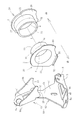
以下、図面に基づいて一実施例を説明する。図1は本実施例に係る筒型金具1の斜視図、図2は筒型金具1の正面図、図3は側面図、図4は平面図、図5は斜め下方から底面側を示す図、図6は図3の6−6線断面図、図7は図4の7−7線断面図、図8は構成部品の分解斜視図である。
An embodiment will be described below with reference to the drawings. 1 is a perspective view of a
筒型金具1は筒部2の軸方向両側にフランジ3が開口4の周縁から折り返して一体に形成されている。
フランジ3及び筒部2には、第1の取付用脚部5が筒部2の軸方向Lに沿って左右へ張り出すように溶接で取付けられている。また、筒部2の外周部には筒部2の径方向へ突出する第2の取付用脚部6が溶接で取付けられている。これら第1の取付用脚部5及び第2の取付用脚部6には、それぞれ取付穴5a,6aが設けられ、ここでボルト7(図7)により、図示しない車体へ取付けられている。
The
A
筒部2の内側には、公知の防振ゴム8が収容され(図2)、防振ゴム8の中央に一体化されたシャフト9(図2)が筒部2の軸方向Lに沿って延び、開口4から出て図示しないエンジンへ取付けられている。また、軸方向Lを前後方向へ向けて配置してある(図7)。これにより、エンジンの振動を防振ゴム8で吸収して車体側への伝達を遮断するとともに、軸方向L上から入力する加速時及び減速時におけるエンジンの荷重を吸収する。
A known anti-vibration rubber 8 is accommodated inside the cylindrical portion 2 (FIG. 2), and a shaft 9 (FIG. 2) integrated in the center of the anti-vibration rubber 8 is along the axial direction L of the
以下、図8を中心に説明する。筒部2と左右のフランジ3を一体化した本体部分は筒部2の軸方向Lにて左右に分割された第1の分割体10と第2の分割体20とで構成され、さらに別体で形成された第1の取付用脚部5及び第2の取付用脚部6を溶接して組立てられるものであり、全体として4個の独立した別体部品で構成され、これら構成部品は、それぞれ鋼板をプレス成形して製造される。
Hereinafter, description will be made with reference to FIG. The main body portion in which the
第1の分割体10及び第2の分割体20は、互いに内外へ嵌合する分割筒部11,21と、それぞれの軸方向一端側に一体化されたフランジ3とを備え、本実施例では外側へ重なる分割筒部21が大径であり、かつ内側へ重なる分割筒部11が小径となっている。
The
分割筒部11と分割筒部21の嵌合は、圧入もしくはほとんど力を要さずに出入り自在に嵌合できる程度の遊嵌状であってもよい。圧入の場合は、圧入のみで第1の分割体10と第2の分割体20を結合一体化できる。
また、緩く嵌合する場合は、嵌合部を全周溶接することにより一体化される。いずれの場合も内外に重なり合うラップ代12,22を有する。
The fitting of the divided
Moreover, when fitting loosely, it integrates by welding a fitting part perimeter. In either case, it has
第1の分割体10,第2の分割体20ともフランジ3はほぼ同形であり、一部が径方向へ張り出す張り出し部30及び31を一体に有する。従来の一般的な深絞りプレス成形では、張り出し部30,31を除く部分程度の大きさしか一体に成形できず、これらの張り出し部30,31は、従来の一般的な深絞りプレス成形では成形困難な程に大きなものである。
本実施例では、第1の分割体10,第2の分割体20に分割して形成することにより、従来の筒部よりも短い分割筒部と一方側のフランジのみを形成することで済むため、特別な深絞り成形をせずに一般的な深絞りプレス成形で余裕を持って形成できる。
The
In the present embodiment, since the first divided
さらに、張り出し部31は先端を略90°折り曲げて先端が略水平な水平縁部32とし、ここで第1の取付用脚部5側へ溶接可能になっている。また、フランジ3の一部には、直線状に上下方向へカットした垂直縁部33が形成され、ここでも第1の取付用脚部5へ溶接できるようになっている。
Further, the protruding
第1の取付用脚部5は、筒部2の軸方向Lと略平行な水平壁40を左右に備え、左右の水平壁40の中間部は左右のフランジ3の間へ入り込む段差部41になっている。水平壁40には、段差部41の外側で水平縁部32が重なり、ここで水平縁部32と溶接される(図1,4,7参照)。
The first
また、水平壁40と直角に曲がる垂直壁42を備え、この垂直壁42の垂直な平坦面にフランジ3の垂直縁部33が当接するので、この当接部で溶接できる(図1,2,6参照)。
このように、第1の取付用脚部5へ水平壁40と垂直壁42を設け、一方、フランジ3に水平縁部32と垂直縁部33を設けることにより、第1の取付用脚部5とフランジ3の溶接が可能になった。
Further, a
Thus, the first mounting
また、第1の取付用脚部5には、段差部41を挟んで垂直壁42と対面するように斜めの突出部43が一体に形成され、この部分は筒部2の外周に沿い、先端部で筒部2の外周と溶接される(図6参照)。
In addition, the first mounting
この各構成部を組立一体化した状態では、図1に示すように、筒部2の表面には外側の分割筒部21における先端23が出ているが、突出部43はこの先端23を跨いで、ラップ代12以外の分割筒部11とラップ代22の双方へ重なり、ラップ代22に対して溶接される。また左右の水平壁40と連続して第1の取付用脚部5と一体であるから、突出部43の補強により、分割筒部11と21の接続剛性を高めることができる(図3,4,7参照)。
In the state where these components are assembled and integrated, as shown in FIG. 1, the
なお、水平壁40は段差部41を挟んで筒部2の左右へ連続する一枚物として形成され、水平壁40の水平縁部32との接合部より外側に取付穴5aが形成されている(図5,7参照)。
The
各ラップ代12及び22は同幅であり、分割筒部11及び21は、ラップ代12及び22にてラップ幅d(図7)で重なる部分と、ラップしない部分とを備え、分割筒部21の先端23は上側(外側)、分割筒部11の先端13は下側(内側)に位置し、分割筒部21の先端23に沿って溶接される(図3・4・7参照)。
The
図1及び図4に示すように、第2の取付用脚部6は左右のフランジ3の間へ入る幅の左右壁50a,50bを備え、その間の平坦部51が筒部2の軸方向幅より若干狭い程度であり、基端側の屈曲部52及び各左右壁50a,50b(第2の取付用脚部6については左右壁と表現するものとする)の基端側に形成された湾曲部53(図8参照)が筒部2の外周へ当接して溶接される。
なお、左右壁50a,50bの湾曲部53は、当接相手の第1の分割体10及び第2の分割体20の径相違に応じて湾曲程度が相違している。
As shown in FIGS. 1 and 4, the second mounting
Note that the bending
このとき、屈曲部52は先端23を跨いでラップ代22と溶接され(図4・5・6)、かつ一方の左右壁50aが分割筒部11へ、他方の左右壁50bが分割筒部21へ溶接されることにより、やはり第1の分割体10と第2の分割体20の結合剛性を高めている。(図1・4・6参照)。
At this time, the
次に、この筒型金具1の製造方法を説明する。まず、第1の取付用脚部5、第2の取付用脚部6、第1の分割体10、第2の分割体20をそれぞれ別々に板材からプレス成形する。このとき、第1の分割体10、第2の分割体20はそれぞれ従来の筒部両側にフランジがあるものに対して、筒部で2分割したものに相当するため、分割筒部11及び21の各軸方向一端部にそれぞれフランジ3を一体にした状態で通常の深絞り成形により容易に形成できる。
また、分割筒部21が大径となる第2の分割体20は、第1の分割体10よりも板厚の大きなものを用いる。
Next, the manufacturing method of this
In addition, the second divided
次に、第1の分割体10と第2の分割体20を組立てる。このとき、小径の分割体10を内側にして大径の分割体20が外側となるよう、分割筒部11と分割筒部21の各ラップ代12と22を内外に重なるよう圧入する。これにより、分割筒部11と21が一体化するので、要求される結合剛性の程度によっては、この状態で第1の分割体10と第2の分割体20の一体化が完了して筒部2となる。
Next, the first divided
しかし、本実施例では、先端23に沿って全周を溶接し、さらに結合強度を高めている。このようにして分割筒部11及び21が一体化された筒部2に対して、第1の取付用脚部5と第2の取付用脚部6を取付ける。
However, in this embodiment, the entire circumference is welded along the
まず、第1の取付用脚部5は段差部41を左右のフランジ3間に入れ、水平縁部32を水平壁40に重ねて水平縁部32に沿って溶接する。また、垂直縁部33を垂直壁42に当接し、この当接部に沿って溶接する。
First, the first mounting
さらに、突出部43を筒部2の外周面に重ねて、先端23を跨がせ、突出部43の縁に沿ってラップ代22へ溶接する。これにより、第1の取付用脚部5は高強度で筒部2へ溶接され、かつ分割筒部11と21の結合剛性も高くなる。
Further, the protruding
続いて、第2の取付用脚部6を取付ける。第2の取付用脚部6の基部側を左右のフランジ3間へ入れて、屈曲部52及び湾曲部53をそれぞれ筒部2の外周に沿わせ、それぞれの当接部に沿って溶接する。このとき、屈曲部52は先端23を跨いでラップ代22へ溶接されるので、やはり第2の取付用脚部6の結合強度を高くし、かつ分割筒部11と21の結合剛性を高める。
Subsequently, the second mounting
このように、分割筒部11と21の間における溶接部A、水平縁部32と水平壁40の間における溶接部B、垂直縁部33と垂直壁42との溶接部C、突出部43とラップ代22に対する溶接部D、屈曲部52及び湾曲部53とラップ代22及び分割筒部11に対する溶接部Eの計5ケ所における溶接で強固に一体化された筒型金具1となる(図1)。
As described above, the welded portion A between the divided
次に、使用方法を説明する。図2に示すように、筒部2の内側に防振ゴム8を一体化して、筒型防振装置を構成し、第1の取付用脚部5を車体側のフレーム上へ置き、軸方向Lを前後方向に合わせる。このとき、図7に示すように、肉厚が大きく高剛性の第2の分割体20を後方側に配置し、第1の分割体10を前方側に向け、第1の取付用脚部5を取付穴5aで筒型金具1を通して車体側へ固定する。また、シャフト9をエンジン側へ取付ける。
Next, the usage method will be described. As shown in FIG. 2, a vibration isolating rubber 8 is integrated inside the
このようにすると、エンジンの振動は、シャフト9から防振ゴム8へ伝達され、防振ゴム8にて吸収されるため、車体への振動伝達を遮断できる。
また、走行中において、急加速時には、エンジンの荷重が防振ゴム8を介してシャフト9から第1の分割体10側へかかる。しかし、分割筒部11と分割筒部21はラップ代12と22が内外に重なって一体化されて高剛性になっているため、急加速時の大荷重に対して十分に耐えることができる。
In this way, the vibration of the engine is transmitted from the shaft 9 to the anti-vibration rubber 8 and absorbed by the anti-vibration rubber 8, so that vibration transmission to the vehicle body can be blocked.
Further, during traveling, during sudden acceleration, the engine load is applied from the shaft 9 to the first divided
しかも、第1の取付用脚部5及び第2の取付用脚部6がラップ代12及び22を跨いで溶接されていることによっても、結合剛性を高めている。
さらに、急減速時には、エンジンが急速に前方へ相対移動するため、より大きな荷重が第2の分割体20側へかかる。しかし、第2の分割体20は第1の分割体10より肉厚が大きく高剛性になっているので、このようなより大きな荷重にも十分耐えることができる。
Moreover, the first and second mounting
Furthermore, at the time of sudden deceleration, the engine rapidly moves relatively forward, so that a larger load is applied to the second divided
しかも、肉厚を大きくするのは、このような事態においてより高い剛性が要求される第2の分割体20側だけで済み、筒部2全体を厚肉にする必要がないので、実際に変化させることができるとともに、全体として軽量化及びコストダウンを実現できる。そのうえ、筒部2は分割筒部11及び21のラップ代12及び22の重なり合いで、防振装置1全体として部分的に高剛性になっている。
In addition, the thickness is increased only on the second divided
なお、この実施例は、筒部2,第1の取付用脚部5,第2の取付用脚部6からなる従来例に比べて、筒部2を第1の分割体10と第2の分割体20に分割した4部品で構成されている。このため、製造は容易になり、かつ筒部2の剛性を高めることができ、かつ剛性分布を実情に適合させて変化させることができるが、構成部品点数としては1点増加することになる。
In this embodiment, the
そこで、従来と同じ3部品で構成できるようにした別実施例を図9に示す。図9は図8と同様に構成部品を分解した斜視図である。
この実施例における筒型金具1は、筒部及びフランジを含む本体部分を、第1の分割体10と第2の分割体20に分割した点は前実施例と同様であるが、前実施例における第1の取付用脚部5と第2の取付用脚部6を一体化した単一部品の複合取付用脚部60を設けた点が相違する。
FIG. 9 shows another embodiment in which the same three parts as in the prior art can be configured. FIG. 9 is an exploded perspective view of components as in FIG.
The cylindrical metal fitting 1 in this embodiment is the same as the previous embodiment in that the main body portion including the cylinder portion and the flange is divided into the first divided
なお、前実施例と共通部は共有符号を用いる。また、複合取付用脚部60も第1の取付用脚部5と第2の取付用脚部6を一体化したものであるので、構成各部については第1の取付用脚部5と第2の取付用脚部6の共通符号を用いるものとする。
In addition, a common code | symbol is used for a common part with the previous Example. Further, since the
この例では、複合取付用脚部60が第1の取付用脚部5の垂直壁42と第2の取付用脚部6の屈曲部52とを連続一体化する連続部61により、第1の取付用脚部5に相当する第1取付用脚部62と第2の取付用脚部6に相当する第2取付用脚部63とを連続一体化して構成されている。
In this example, the
第1取付用脚部62と第2取付用脚部63はそれぞれ第1の取付用脚部5と第2の取付用脚部6の構造をそのまま保有している。したがって、第1取付用脚部62及び第2取付用脚部63と筒部2との溶接組立方法は、第1の取付用脚部5及び第2の取付用脚部6を溶接する場合と同じである。
The first mounting
この複合取付用脚部60を形成するには、一枚の板材から、第1の取付用脚部5及び第2の取付用脚部6の展開形状を連続部61で連続一体化した状態でカットし、これをプレス成形により、第1取付用脚部62及び第2取付用脚部63の各部を折り曲げ等すれば、複合取付用脚部60を得ることができる。
In order to form the
このようにすると、筒型金具1を構成する部品点数は、第1の分割体10,第2の分割体20及び複合取付用脚部60の3部品となり、従来と同じ部品点数となるから、部品点数の点でも同じとなり、さらに製造上有利なものとなる。
If it does in this way, the number of parts which constitutes
なお、本願発明は上記の各実施例に限定されるものではなく、発明の原理内において種々に変形や応用が可能である。例えば、分割筒部11と分割筒部21は溶接せず圧入だけで一体化することもでき、このとき、第1の取付用脚部5及び第2の取付用脚部6がオーバーラップ部を跨いで溶接すれば、圧入だけの結合剛性を第1の取付用脚部5及び第2の取付用脚部6の利用により十分高くすることができる。
The present invention is not limited to the above-described embodiments, and various modifications and applications can be made within the principle of the invention. For example, the divided
また、第1の分割体10と第2の分割体20は肉厚だけでなく、材質や強度等を異なるもの同士を組み合わせてもよい。このようにすると、さらに要求される剛性や強度により適合させることができる。
Further, the first divided
1:筒型金具、2:筒部、3:フランジ、4:開口、5:第1の取付用脚部、6:第2の取付用脚部、10:第1の分割体、11:分割筒部、12:ラップ代、13:先端、20:第2の分割体、21:分割筒部、22:ラップ代、23:先端、32:水平縁部、33:垂直縁部、40:水平壁、42:垂直壁 1: cylindrical fitting, 2: cylindrical portion, 3: flange, 4: opening, 5: first mounting leg, 6: second mounting leg, 10: first divided body, 11: divided Tube portion, 12: Lapping allowance, 13: Tip, 20: Second divided body, 21: Divided tube portion, 22: Lapping allowance, 23: Tip, 32: Horizontal edge, 33: Vertical edge, 40: Horizontal Wall, 42: vertical wall
Claims (6)
前記筒部を軸方向にて、第1の分割体(10)と第2の分割体(20)とに分割し、
第1及び第2の分割体はそれぞれ分割筒部(11、21)とその軸方向一端側へ一体に形成されたフランジ(3)とを備え、
各分割筒部は、軸方向にて重なり合うラップ代(12,22)を有し、
両ラップ代を軸方向にて重ね合わせて両分割筒部を内外に嵌合し、相互に一体化してなり、
前記第1の分割体(10)と第2の分割体(20)は肉厚が相対的に大小に異なり、
前記筒型防振装置は、軸方向を車両の前後方向に向けて配置され、
前記肉厚が薄い方の分割体を減速側入力方向へ配置し、
他方の肉厚がより厚い分割筒部を、加速側入力方向へ配置したことを特徴とする筒型防振装置用筒型金具。 A cylindrical metal fitting (1) used for a cylindrical vibration isolator, and a main body portion integrally provided with a cylindrical portion (2) and flanges (3) provided at openings at both axial ends thereof, and the main body In the cylindrical metal fitting for a cylindrical vibration isolator provided with a mounting leg welded to the part,
The cylindrical portion is divided in the axial direction into a first divided body (10) and a second divided body (20),
Each of the first and second divided bodies includes a divided cylindrical portion (11, 21) and a flange (3) integrally formed on one axial end side thereof,
Each divided tube portion has a lapping margin (12, 22) overlapping in the axial direction,
Both lap allowances are overlapped in the axial direction, both split cylinder parts are fitted inside and outside, and integrated with each other,
The first divided body (10) and the second divided body (20) are relatively different in thickness.
The cylindrical vibration isolator is arranged with the axial direction facing the front-rear direction of the vehicle,
The thinner divided body is arranged in the deceleration side input direction,
A cylindrical bracket for a cylindrical vibration isolator, wherein the other divided cylindrical portion is disposed in the acceleration side input direction.
Priority Applications (1)
| Application Number | Priority Date | Filing Date | Title |
|---|---|---|---|
| JP2008154737A JP5202121B2 (en) | 2008-06-12 | 2008-06-12 | Cylindrical bracket for cylindrical vibration isolator |
Applications Claiming Priority (1)
| Application Number | Priority Date | Filing Date | Title |
|---|---|---|---|
| JP2008154737A JP5202121B2 (en) | 2008-06-12 | 2008-06-12 | Cylindrical bracket for cylindrical vibration isolator |
Publications (2)
| Publication Number | Publication Date |
|---|---|
| JP2009299781A JP2009299781A (en) | 2009-12-24 |
| JP5202121B2 true JP5202121B2 (en) | 2013-06-05 |
Family
ID=41546889
Family Applications (1)
| Application Number | Title | Priority Date | Filing Date |
|---|---|---|---|
| JP2008154737A Expired - Fee Related JP5202121B2 (en) | 2008-06-12 | 2008-06-12 | Cylindrical bracket for cylindrical vibration isolator |
Country Status (1)
| Country | Link |
|---|---|
| JP (1) | JP5202121B2 (en) |
Family Cites Families (3)
| Publication number | Priority date | Publication date | Assignee | Title |
|---|---|---|---|---|
| JPH05240282A (en) * | 1992-02-24 | 1993-09-17 | Yamakawa Ind Co Ltd | Bracket for engine mount |
| JPH08152034A (en) * | 1994-11-28 | 1996-06-11 | Tokai Rubber Ind Ltd | Engine mount attaching member |
| JP3613928B2 (en) * | 1997-04-30 | 2005-01-26 | 日産自動車株式会社 | Engine mount device |
-
2008
- 2008-06-12 JP JP2008154737A patent/JP5202121B2/en not_active Expired - Fee Related
Also Published As
| Publication number | Publication date |
|---|---|
| JP2009299781A (en) | 2009-12-24 |
Similar Documents
| Publication | Publication Date | Title |
|---|---|---|
| JP4959462B2 (en) | Anti-vibration device manufacturing method | |
| WO2006040741A1 (en) | Subframe for motor vehicle | |
| JP6157000B2 (en) | Vibration isolator | |
| JP6076845B2 (en) | Pedal arm | |
| JP6494321B2 (en) | Anti-vibration device bracket, anti-vibration device with bracket, and manufacturing method of anti-vibration device bracket | |
| JP5090238B2 (en) | Operation pedal device for vehicle | |
| JP5739242B2 (en) | Beam member | |
| US20040149078A1 (en) | Method of fabricating a housing assembly | |
| JP2007062675A (en) | Suspension arm for vehicle | |
| JP5202121B2 (en) | Cylindrical bracket for cylindrical vibration isolator | |
| JP5595702B2 (en) | Torque rod | |
| JP5172502B2 (en) | Body frame connection structure and molding method | |
| JP6113501B2 (en) | Anti-vibration connecting rod | |
| JP5560573B2 (en) | Metal plate joining method, joining apparatus and joined product | |
| KR101009631B1 (en) | Method for making axle housing | |
| KR101101410B1 (en) | Axle housing | |
| JP5637904B2 (en) | Member connection structure | |
| CN112823114B (en) | Engine bracket for motor vehicle | |
| JP2010207859A (en) | Method and device for joining metal sheets and joined product | |
| JP3787929B2 (en) | Body joint structure | |
| WO2012086118A1 (en) | Vibration prevention device and manufacturing method therefor | |
| JP2000006870A (en) | Rear frame of motor-bicycle, etc. | |
| JP2021169105A (en) | Structural member for vehicle and method for manufacturing the same | |
| JP4920261B2 (en) | Axle tube | |
| KR20070092843A (en) | Steering assembly and manucturing method thereof |
Legal Events
| Date | Code | Title | Description |
|---|---|---|---|
| A621 | Written request for application examination |
Free format text: JAPANESE INTERMEDIATE CODE: A621 Effective date: 20110603 |
|
| A131 | Notification of reasons for refusal |
Free format text: JAPANESE INTERMEDIATE CODE: A131 Effective date: 20120314 |
|
| A977 | Report on retrieval |
Free format text: JAPANESE INTERMEDIATE CODE: A971007 Effective date: 20120315 |
|
| A521 | Written amendment |
Free format text: JAPANESE INTERMEDIATE CODE: A523 Effective date: 20120514 |
|
| A131 | Notification of reasons for refusal |
Free format text: JAPANESE INTERMEDIATE CODE: A131 Effective date: 20121030 |
|
| A521 | Written amendment |
Free format text: JAPANESE INTERMEDIATE CODE: A523 Effective date: 20121220 |
|
| TRDD | Decision of grant or rejection written | ||
| A01 | Written decision to grant a patent or to grant a registration (utility model) |
Free format text: JAPANESE INTERMEDIATE CODE: A01 Effective date: 20130130 |
|
| A61 | First payment of annual fees (during grant procedure) |
Free format text: JAPANESE INTERMEDIATE CODE: A61 Effective date: 20130212 |
|
| R150 | Certificate of patent or registration of utility model |
Free format text: JAPANESE INTERMEDIATE CODE: R150 |
|
| FPAY | Renewal fee payment (event date is renewal date of database) |
Free format text: PAYMENT UNTIL: 20160222 Year of fee payment: 3 |
|
| R250 | Receipt of annual fees |
Free format text: JAPANESE INTERMEDIATE CODE: R250 |
|
| LAPS | Cancellation because of no payment of annual fees |