JP5201426B2 - Lithium ion battery and its use - Google Patents
Lithium ion battery and its use Download PDFInfo
- Publication number
- JP5201426B2 JP5201426B2 JP2010504357A JP2010504357A JP5201426B2 JP 5201426 B2 JP5201426 B2 JP 5201426B2 JP 2010504357 A JP2010504357 A JP 2010504357A JP 2010504357 A JP2010504357 A JP 2010504357A JP 5201426 B2 JP5201426 B2 JP 5201426B2
- Authority
- JP
- Japan
- Prior art keywords
- active material
- negative electrode
- material layer
- electrode active
- inorganic layer
- Prior art date
- Legal status (The legal status is an assumption and is not a legal conclusion. Google has not performed a legal analysis and makes no representation as to the accuracy of the status listed.)
- Active
Links
- 229910001416 lithium ion Inorganic materials 0.000 title claims description 95
- HBBGRARXTFLTSG-UHFFFAOYSA-N Lithium ion Chemical compound [Li+] HBBGRARXTFLTSG-UHFFFAOYSA-N 0.000 title claims description 84
- 239000007773 negative electrode material Substances 0.000 claims description 192
- 239000011149 active material Substances 0.000 claims description 73
- 239000002002 slurry Substances 0.000 claims description 68
- 238000000034 method Methods 0.000 claims description 47
- 239000007774 positive electrode material Substances 0.000 claims description 46
- 239000011230 binding agent Substances 0.000 claims description 34
- 239000010954 inorganic particle Substances 0.000 claims description 20
- 238000004519 manufacturing process Methods 0.000 claims description 11
- 238000004804 winding Methods 0.000 claims description 10
- 239000011255 nonaqueous electrolyte Substances 0.000 claims description 9
- 239000006183 anode active material Substances 0.000 claims 1
- 239000010410 layer Substances 0.000 description 412
- 239000002245 particle Substances 0.000 description 50
- 239000011248 coating agent Substances 0.000 description 26
- 239000000463 material Substances 0.000 description 24
- 239000000203 mixture Substances 0.000 description 24
- 230000015572 biosynthetic process Effects 0.000 description 23
- 230000002265 prevention Effects 0.000 description 19
- 239000002904 solvent Substances 0.000 description 17
- 239000008151 electrolyte solution Substances 0.000 description 15
- 239000007788 liquid Substances 0.000 description 15
- OKTJSMMVPCPJKN-UHFFFAOYSA-N Carbon Chemical compound [C] OKTJSMMVPCPJKN-UHFFFAOYSA-N 0.000 description 14
- 230000000694 effects Effects 0.000 description 13
- 238000001035 drying Methods 0.000 description 12
- 239000011254 layer-forming composition Substances 0.000 description 12
- 229910052751 metal Inorganic materials 0.000 description 12
- 239000002184 metal Substances 0.000 description 12
- RYGMFSIKBFXOCR-UHFFFAOYSA-N Copper Chemical compound [Cu] RYGMFSIKBFXOCR-UHFFFAOYSA-N 0.000 description 11
- 238000007600 charging Methods 0.000 description 11
- 238000000576 coating method Methods 0.000 description 11
- XLYOFNOQVPJJNP-UHFFFAOYSA-N water Substances O XLYOFNOQVPJJNP-UHFFFAOYSA-N 0.000 description 11
- PNEYBMLMFCGWSK-UHFFFAOYSA-N aluminium oxide Inorganic materials [O-2].[O-2].[O-2].[Al+3].[Al+3] PNEYBMLMFCGWSK-UHFFFAOYSA-N 0.000 description 10
- 239000012528 membrane Substances 0.000 description 9
- 239000011889 copper foil Substances 0.000 description 8
- 239000011888 foil Substances 0.000 description 8
- 229910052782 aluminium Inorganic materials 0.000 description 7
- XAGFODPZIPBFFR-UHFFFAOYSA-N aluminium Chemical compound [Al] XAGFODPZIPBFFR-UHFFFAOYSA-N 0.000 description 7
- 238000005516 engineering process Methods 0.000 description 7
- 238000002156 mixing Methods 0.000 description 7
- 239000003960 organic solvent Substances 0.000 description 7
- 229910052799 carbon Inorganic materials 0.000 description 6
- 238000001816 cooling Methods 0.000 description 6
- -1 for example Substances 0.000 description 6
- 230000001965 increasing effect Effects 0.000 description 6
- 238000004898 kneading Methods 0.000 description 6
- 229920000642 polymer Polymers 0.000 description 6
- 239000011148 porous material Substances 0.000 description 6
- 238000002360 preparation method Methods 0.000 description 6
- 230000008569 process Effects 0.000 description 6
- 239000003575 carbonaceous material Substances 0.000 description 5
- 239000012046 mixed solvent Substances 0.000 description 5
- 239000000843 powder Substances 0.000 description 5
- 230000002829 reductive effect Effects 0.000 description 5
- 229920005989 resin Polymers 0.000 description 5
- 239000011347 resin Substances 0.000 description 5
- 229920002134 Carboxymethyl cellulose Polymers 0.000 description 4
- SECXISVLQFMRJM-UHFFFAOYSA-N N-Methylpyrrolidone Chemical compound CN1CCCC1=O SECXISVLQFMRJM-UHFFFAOYSA-N 0.000 description 4
- 239000002033 PVDF binder Substances 0.000 description 4
- 230000002411 adverse Effects 0.000 description 4
- 239000004020 conductor Substances 0.000 description 4
- 229920001577 copolymer Polymers 0.000 description 4
- 239000010949 copper Substances 0.000 description 4
- 238000005520 cutting process Methods 0.000 description 4
- 229920001971 elastomer Polymers 0.000 description 4
- 239000007772 electrode material Substances 0.000 description 4
- 239000003792 electrolyte Substances 0.000 description 4
- 230000035515 penetration Effects 0.000 description 4
- 229920002981 polyvinylidene fluoride Polymers 0.000 description 4
- 230000000452 restraining effect Effects 0.000 description 4
- 239000005060 rubber Substances 0.000 description 4
- KMTRUDSVKNLOMY-UHFFFAOYSA-N Ethylene carbonate Chemical compound O=C1OCCO1 KMTRUDSVKNLOMY-UHFFFAOYSA-N 0.000 description 3
- PXHVJJICTQNCMI-UHFFFAOYSA-N Nickel Chemical compound [Ni] PXHVJJICTQNCMI-UHFFFAOYSA-N 0.000 description 3
- 239000004743 Polypropylene Substances 0.000 description 3
- 238000002441 X-ray diffraction Methods 0.000 description 3
- 239000001768 carboxy methyl cellulose Substances 0.000 description 3
- 235000010948 carboxy methyl cellulose Nutrition 0.000 description 3
- 239000008112 carboxymethyl-cellulose Substances 0.000 description 3
- 230000008859 change Effects 0.000 description 3
- 238000006243 chemical reaction Methods 0.000 description 3
- 229910052802 copper Inorganic materials 0.000 description 3
- 238000007599 discharging Methods 0.000 description 3
- 239000002612 dispersion medium Substances 0.000 description 3
- 238000009826 distribution Methods 0.000 description 3
- JBTWLSYIZRCDFO-UHFFFAOYSA-N ethyl methyl carbonate Chemical compound CCOC(=O)OC JBTWLSYIZRCDFO-UHFFFAOYSA-N 0.000 description 3
- 239000005038 ethylene vinyl acetate Substances 0.000 description 3
- 230000006870 function Effects 0.000 description 3
- 238000002347 injection Methods 0.000 description 3
- 239000007924 injection Substances 0.000 description 3
- 229910010272 inorganic material Inorganic materials 0.000 description 3
- 238000012423 maintenance Methods 0.000 description 3
- 238000005259 measurement Methods 0.000 description 3
- 229920001200 poly(ethylene-vinyl acetate) Polymers 0.000 description 3
- 229920001155 polypropylene Polymers 0.000 description 3
- 229920001343 polytetrafluoroethylene Polymers 0.000 description 3
- 239000004810 polytetrafluoroethylene Substances 0.000 description 3
- 230000009467 reduction Effects 0.000 description 3
- 229920003048 styrene butadiene rubber Polymers 0.000 description 3
- 229920005992 thermoplastic resin Polymers 0.000 description 3
- 238000012546 transfer Methods 0.000 description 3
- OIFBSDVPJOWBCH-UHFFFAOYSA-N Diethyl carbonate Chemical compound CCOC(=O)OCC OIFBSDVPJOWBCH-UHFFFAOYSA-N 0.000 description 2
- 229910013290 LiNiO 2 Inorganic materials 0.000 description 2
- 229910013870 LiPF 6 Inorganic materials 0.000 description 2
- WHXSMMKQMYFTQS-UHFFFAOYSA-N Lithium Chemical compound [Li] WHXSMMKQMYFTQS-UHFFFAOYSA-N 0.000 description 2
- 229910052774 Proactinium Inorganic materials 0.000 description 2
- 239000002174 Styrene-butadiene Substances 0.000 description 2
- MCMNRKCIXSYSNV-UHFFFAOYSA-N Zirconium dioxide Chemical compound O=[Zr]=O MCMNRKCIXSYSNV-UHFFFAOYSA-N 0.000 description 2
- 239000006230 acetylene black Substances 0.000 description 2
- 239000003125 aqueous solvent Substances 0.000 description 2
- 238000010276 construction Methods 0.000 description 2
- 238000007334 copolymerization reaction Methods 0.000 description 2
- 230000003247 decreasing effect Effects 0.000 description 2
- IEJIGPNLZYLLBP-UHFFFAOYSA-N dimethyl carbonate Chemical compound COC(=O)OC IEJIGPNLZYLLBP-UHFFFAOYSA-N 0.000 description 2
- 238000002474 experimental method Methods 0.000 description 2
- 238000011049 filling Methods 0.000 description 2
- 239000000446 fuel Substances 0.000 description 2
- 229910002804 graphite Inorganic materials 0.000 description 2
- 239000010439 graphite Substances 0.000 description 2
- 150000002484 inorganic compounds Chemical class 0.000 description 2
- 229910052745 lead Inorganic materials 0.000 description 2
- 229910052744 lithium Inorganic materials 0.000 description 2
- 230000014759 maintenance of location Effects 0.000 description 2
- 239000002931 mesocarbon microbead Substances 0.000 description 2
- 239000003607 modifier Substances 0.000 description 2
- 229910021382 natural graphite Inorganic materials 0.000 description 2
- 230000035699 permeability Effects 0.000 description 2
- 229920005569 poly(vinylidene fluoride-co-hexafluoropropylene) Polymers 0.000 description 2
- 229920000058 polyacrylate Polymers 0.000 description 2
- 239000002244 precipitate Substances 0.000 description 2
- 239000011164 primary particle Substances 0.000 description 2
- 239000000047 product Substances 0.000 description 2
- RUOJZAUFBMNUDX-UHFFFAOYSA-N propylene carbonate Chemical compound CC1COC(=O)O1 RUOJZAUFBMNUDX-UHFFFAOYSA-N 0.000 description 2
- 239000002994 raw material Substances 0.000 description 2
- 150000003839 salts Chemical class 0.000 description 2
- 229910021332 silicide Inorganic materials 0.000 description 2
- FVBUAEGBCNSCDD-UHFFFAOYSA-N silicide(4-) Chemical compound [Si-4] FVBUAEGBCNSCDD-UHFFFAOYSA-N 0.000 description 2
- 239000007787 solid Substances 0.000 description 2
- SMZOUWXMTYCWNB-UHFFFAOYSA-N 2-(2-methoxy-5-methylphenyl)ethanamine Chemical compound COC1=CC=C(C)C=C1CCN SMZOUWXMTYCWNB-UHFFFAOYSA-N 0.000 description 1
- NIXOWILDQLNWCW-UHFFFAOYSA-N 2-Propenoic acid Natural products OC(=O)C=C NIXOWILDQLNWCW-UHFFFAOYSA-N 0.000 description 1
- NLHHRLWOUZZQLW-UHFFFAOYSA-N Acrylonitrile Chemical compound C=CC#N NLHHRLWOUZZQLW-UHFFFAOYSA-N 0.000 description 1
- 229910018072 Al 2 O 3 Inorganic materials 0.000 description 1
- PIGFYZPCRLYGLF-UHFFFAOYSA-N Aluminum nitride Chemical compound [Al]#N PIGFYZPCRLYGLF-UHFFFAOYSA-N 0.000 description 1
- 229910000881 Cu alloy Inorganic materials 0.000 description 1
- 229910012851 LiCoO 2 Inorganic materials 0.000 description 1
- 229910015643 LiMn 2 O 4 Inorganic materials 0.000 description 1
- CPLXHLVBOLITMK-UHFFFAOYSA-N Magnesium oxide Chemical compound [Mg]=O CPLXHLVBOLITMK-UHFFFAOYSA-N 0.000 description 1
- CERQOIWHTDAKMF-UHFFFAOYSA-N Methacrylic acid Chemical compound CC(=C)C(O)=O CERQOIWHTDAKMF-UHFFFAOYSA-N 0.000 description 1
- 239000004698 Polyethylene Substances 0.000 description 1
- VYPSYNLAJGMNEJ-UHFFFAOYSA-N Silicium dioxide Chemical compound O=[Si]=O VYPSYNLAJGMNEJ-UHFFFAOYSA-N 0.000 description 1
- RTAQQCXQSZGOHL-UHFFFAOYSA-N Titanium Chemical compound [Ti] RTAQQCXQSZGOHL-UHFFFAOYSA-N 0.000 description 1
- 125000005396 acrylic acid ester group Chemical group 0.000 description 1
- 230000009471 action Effects 0.000 description 1
- 125000005907 alkyl ester group Chemical group 0.000 description 1
- 229910045601 alloy Inorganic materials 0.000 description 1
- 239000000956 alloy Substances 0.000 description 1
- 238000013459 approach Methods 0.000 description 1
- 230000008901 benefit Effects 0.000 description 1
- DQXBYHZEEUGOBF-UHFFFAOYSA-N but-3-enoic acid;ethene Chemical compound C=C.OC(=O)CC=C DQXBYHZEEUGOBF-UHFFFAOYSA-N 0.000 description 1
- 239000006229 carbon black Substances 0.000 description 1
- 235000019241 carbon black Nutrition 0.000 description 1
- 150000004649 carbonic acid derivatives Chemical class 0.000 description 1
- 239000000919 ceramic Substances 0.000 description 1
- 238000010277 constant-current charging Methods 0.000 description 1
- 238000010281 constant-current constant-voltage charging Methods 0.000 description 1
- 239000000470 constituent Substances 0.000 description 1
- 239000012809 cooling fluid Substances 0.000 description 1
- 230000001351 cycling effect Effects 0.000 description 1
- 238000000354 decomposition reaction Methods 0.000 description 1
- 230000008021 deposition Effects 0.000 description 1
- 238000013461 design Methods 0.000 description 1
- 230000006866 deterioration Effects 0.000 description 1
- 238000010586 diagram Methods 0.000 description 1
- 239000006185 dispersion Substances 0.000 description 1
- 238000005868 electrolysis reaction Methods 0.000 description 1
- 230000002708 enhancing effect Effects 0.000 description 1
- 238000011156 evaluation Methods 0.000 description 1
- 239000004744 fabric Substances 0.000 description 1
- 239000000945 filler Substances 0.000 description 1
- 239000006232 furnace black Substances 0.000 description 1
- 229910021469 graphitizable carbon Inorganic materials 0.000 description 1
- 229910021385 hard carbon Inorganic materials 0.000 description 1
- 230000009931 harmful effect Effects 0.000 description 1
- 230000001771 impaired effect Effects 0.000 description 1
- 230000006872 improvement Effects 0.000 description 1
- 239000011147 inorganic material Substances 0.000 description 1
- 229910052809 inorganic oxide Inorganic materials 0.000 description 1
- 238000005342 ion exchange Methods 0.000 description 1
- 150000002500 ions Chemical class 0.000 description 1
- 239000003273 ketjen black Substances 0.000 description 1
- 239000005001 laminate film Substances 0.000 description 1
- 238000010030 laminating Methods 0.000 description 1
- 229910021439 lithium cobalt complex oxide Inorganic materials 0.000 description 1
- 229910021445 lithium manganese complex oxide Inorganic materials 0.000 description 1
- 229910021440 lithium nickel complex oxide Inorganic materials 0.000 description 1
- 229910003002 lithium salt Inorganic materials 0.000 description 1
- 159000000002 lithium salts Chemical class 0.000 description 1
- 238000000691 measurement method Methods 0.000 description 1
- 230000007246 mechanism Effects 0.000 description 1
- QSHDDOUJBYECFT-UHFFFAOYSA-N mercury Chemical compound [Hg] QSHDDOUJBYECFT-UHFFFAOYSA-N 0.000 description 1
- 229910052753 mercury Inorganic materials 0.000 description 1
- 125000005397 methacrylic acid ester group Chemical group 0.000 description 1
- 238000012986 modification Methods 0.000 description 1
- 230000004048 modification Effects 0.000 description 1
- 229910052759 nickel Inorganic materials 0.000 description 1
- 150000004767 nitrides Chemical class 0.000 description 1
- 229910021470 non-graphitizable carbon Inorganic materials 0.000 description 1
- 229910052755 nonmetal Inorganic materials 0.000 description 1
- 229920000573 polyethylene Polymers 0.000 description 1
- 229920000098 polyolefin Polymers 0.000 description 1
- 229920005672 polyolefin resin Polymers 0.000 description 1
- 229920002689 polyvinyl acetate Polymers 0.000 description 1
- 239000011118 polyvinyl acetate Substances 0.000 description 1
- 238000003825 pressing Methods 0.000 description 1
- 230000003449 preventive effect Effects 0.000 description 1
- 230000001737 promoting effect Effects 0.000 description 1
- 239000011241 protective layer Substances 0.000 description 1
- 238000007086 side reaction Methods 0.000 description 1
- HBMJWWWQQXIZIP-UHFFFAOYSA-N silicon carbide Chemical compound [Si+]#[C-] HBMJWWWQQXIZIP-UHFFFAOYSA-N 0.000 description 1
- HQVNEWCFYHHQES-UHFFFAOYSA-N silicon nitride Chemical compound N12[Si]34N5[Si]62N3[Si]51N64 HQVNEWCFYHHQES-UHFFFAOYSA-N 0.000 description 1
- 229910021384 soft carbon Inorganic materials 0.000 description 1
- 239000007784 solid electrolyte Substances 0.000 description 1
- 229910052596 spinel Inorganic materials 0.000 description 1
- 239000011029 spinel Substances 0.000 description 1
- 239000007858 starting material Substances 0.000 description 1
- 238000003756 stirring Methods 0.000 description 1
- 238000003860 storage Methods 0.000 description 1
- 239000000126 substance Substances 0.000 description 1
- 230000008961 swelling Effects 0.000 description 1
- 230000002195 synergetic effect Effects 0.000 description 1
- 229920003002 synthetic resin Polymers 0.000 description 1
- 239000000057 synthetic resin Substances 0.000 description 1
- 238000012360 testing method Methods 0.000 description 1
- 239000002562 thickening agent Substances 0.000 description 1
- 239000010936 titanium Substances 0.000 description 1
- 229910052719 titanium Inorganic materials 0.000 description 1
- 239000004034 viscosity adjusting agent Substances 0.000 description 1
- 239000003232 water-soluble binding agent Substances 0.000 description 1
- 238000003466 welding Methods 0.000 description 1
Images


Classifications
-
- H—ELECTRICITY
- H01—ELECTRIC ELEMENTS
- H01M—PROCESSES OR MEANS, e.g. BATTERIES, FOR THE DIRECT CONVERSION OF CHEMICAL ENERGY INTO ELECTRICAL ENERGY
- H01M10/00—Secondary cells; Manufacture thereof
- H01M10/05—Accumulators with non-aqueous electrolyte
- H01M10/058—Construction or manufacture
- H01M10/0587—Construction or manufacture of accumulators having only wound construction elements, i.e. wound positive electrodes, wound negative electrodes and wound separators
-
- H—ELECTRICITY
- H01—ELECTRIC ELEMENTS
- H01M—PROCESSES OR MEANS, e.g. BATTERIES, FOR THE DIRECT CONVERSION OF CHEMICAL ENERGY INTO ELECTRICAL ENERGY
- H01M10/00—Secondary cells; Manufacture thereof
- H01M10/05—Accumulators with non-aqueous electrolyte
- H01M10/052—Li-accumulators
- H01M10/0525—Rocking-chair batteries, i.e. batteries with lithium insertion or intercalation in both electrodes; Lithium-ion batteries
-
- H—ELECTRICITY
- H01—ELECTRIC ELEMENTS
- H01M—PROCESSES OR MEANS, e.g. BATTERIES, FOR THE DIRECT CONVERSION OF CHEMICAL ENERGY INTO ELECTRICAL ENERGY
- H01M10/00—Secondary cells; Manufacture thereof
- H01M10/34—Gastight accumulators
- H01M10/345—Gastight metal hydride accumulators
-
- H—ELECTRICITY
- H01—ELECTRIC ELEMENTS
- H01M—PROCESSES OR MEANS, e.g. BATTERIES, FOR THE DIRECT CONVERSION OF CHEMICAL ENERGY INTO ELECTRICAL ENERGY
- H01M10/00—Secondary cells; Manufacture thereof
- H01M10/42—Methods or arrangements for servicing or maintenance of secondary cells or secondary half-cells
- H01M10/4235—Safety or regulating additives or arrangements in electrodes, separators or electrolyte
-
- H—ELECTRICITY
- H01—ELECTRIC ELEMENTS
- H01M—PROCESSES OR MEANS, e.g. BATTERIES, FOR THE DIRECT CONVERSION OF CHEMICAL ENERGY INTO ELECTRICAL ENERGY
- H01M10/00—Secondary cells; Manufacture thereof
- H01M10/42—Methods or arrangements for servicing or maintenance of secondary cells or secondary half-cells
- H01M10/48—Accumulators combined with arrangements for measuring, testing or indicating the condition of cells, e.g. the level or density of the electrolyte
-
- H—ELECTRICITY
- H01—ELECTRIC ELEMENTS
- H01M—PROCESSES OR MEANS, e.g. BATTERIES, FOR THE DIRECT CONVERSION OF CHEMICAL ENERGY INTO ELECTRICAL ENERGY
- H01M2220/00—Batteries for particular applications
- H01M2220/20—Batteries in motive systems, e.g. vehicle, ship, plane
-
- H—ELECTRICITY
- H01—ELECTRIC ELEMENTS
- H01M—PROCESSES OR MEANS, e.g. BATTERIES, FOR THE DIRECT CONVERSION OF CHEMICAL ENERGY INTO ELECTRICAL ENERGY
- H01M50/00—Constructional details or processes of manufacture of the non-active parts of electrochemical cells other than fuel cells, e.g. hybrid cells
- H01M50/20—Mountings; Secondary casings or frames; Racks, modules or packs; Suspension devices; Shock absorbers; Transport or carrying devices; Holders
- H01M50/204—Racks, modules or packs for multiple batteries or multiple cells
- H01M50/207—Racks, modules or packs for multiple batteries or multiple cells characterised by their shape
- H01M50/209—Racks, modules or packs for multiple batteries or multiple cells characterised by their shape adapted for prismatic or rectangular cells
-
- H—ELECTRICITY
- H01—ELECTRIC ELEMENTS
- H01M—PROCESSES OR MEANS, e.g. BATTERIES, FOR THE DIRECT CONVERSION OF CHEMICAL ENERGY INTO ELECTRICAL ENERGY
- H01M50/00—Constructional details or processes of manufacture of the non-active parts of electrochemical cells other than fuel cells, e.g. hybrid cells
- H01M50/20—Mountings; Secondary casings or frames; Racks, modules or packs; Suspension devices; Shock absorbers; Transport or carrying devices; Holders
- H01M50/218—Mountings; Secondary casings or frames; Racks, modules or packs; Suspension devices; Shock absorbers; Transport or carrying devices; Holders characterised by the material
- H01M50/22—Mountings; Secondary casings or frames; Racks, modules or packs; Suspension devices; Shock absorbers; Transport or carrying devices; Holders characterised by the material of the casings or racks
- H01M50/222—Inorganic material
- H01M50/224—Metals
-
- H—ELECTRICITY
- H01—ELECTRIC ELEMENTS
- H01M—PROCESSES OR MEANS, e.g. BATTERIES, FOR THE DIRECT CONVERSION OF CHEMICAL ENERGY INTO ELECTRICAL ENERGY
- H01M50/00—Constructional details or processes of manufacture of the non-active parts of electrochemical cells other than fuel cells, e.g. hybrid cells
- H01M50/20—Mountings; Secondary casings or frames; Racks, modules or packs; Suspension devices; Shock absorbers; Transport or carrying devices; Holders
- H01M50/218—Mountings; Secondary casings or frames; Racks, modules or packs; Suspension devices; Shock absorbers; Transport or carrying devices; Holders characterised by the material
- H01M50/22—Mountings; Secondary casings or frames; Racks, modules or packs; Suspension devices; Shock absorbers; Transport or carrying devices; Holders characterised by the material of the casings or racks
- H01M50/227—Organic material
-
- H—ELECTRICITY
- H01—ELECTRIC ELEMENTS
- H01M—PROCESSES OR MEANS, e.g. BATTERIES, FOR THE DIRECT CONVERSION OF CHEMICAL ENERGY INTO ELECTRICAL ENERGY
- H01M50/00—Constructional details or processes of manufacture of the non-active parts of electrochemical cells other than fuel cells, e.g. hybrid cells
- H01M50/20—Mountings; Secondary casings or frames; Racks, modules or packs; Suspension devices; Shock absorbers; Transport or carrying devices; Holders
- H01M50/218—Mountings; Secondary casings or frames; Racks, modules or packs; Suspension devices; Shock absorbers; Transport or carrying devices; Holders characterised by the material
- H01M50/22—Mountings; Secondary casings or frames; Racks, modules or packs; Suspension devices; Shock absorbers; Transport or carrying devices; Holders characterised by the material of the casings or racks
- H01M50/231—Mountings; Secondary casings or frames; Racks, modules or packs; Suspension devices; Shock absorbers; Transport or carrying devices; Holders characterised by the material of the casings or racks having a layered structure
-
- Y—GENERAL TAGGING OF NEW TECHNOLOGICAL DEVELOPMENTS; GENERAL TAGGING OF CROSS-SECTIONAL TECHNOLOGIES SPANNING OVER SEVERAL SECTIONS OF THE IPC; TECHNICAL SUBJECTS COVERED BY FORMER USPC CROSS-REFERENCE ART COLLECTIONS [XRACs] AND DIGESTS
- Y02—TECHNOLOGIES OR APPLICATIONS FOR MITIGATION OR ADAPTATION AGAINST CLIMATE CHANGE
- Y02E—REDUCTION OF GREENHOUSE GAS [GHG] EMISSIONS, RELATED TO ENERGY GENERATION, TRANSMISSION OR DISTRIBUTION
- Y02E60/00—Enabling technologies; Technologies with a potential or indirect contribution to GHG emissions mitigation
- Y02E60/10—Energy storage using batteries
-
- Y—GENERAL TAGGING OF NEW TECHNOLOGICAL DEVELOPMENTS; GENERAL TAGGING OF CROSS-SECTIONAL TECHNOLOGIES SPANNING OVER SEVERAL SECTIONS OF THE IPC; TECHNICAL SUBJECTS COVERED BY FORMER USPC CROSS-REFERENCE ART COLLECTIONS [XRACs] AND DIGESTS
- Y02—TECHNOLOGIES OR APPLICATIONS FOR MITIGATION OR ADAPTATION AGAINST CLIMATE CHANGE
- Y02P—CLIMATE CHANGE MITIGATION TECHNOLOGIES IN THE PRODUCTION OR PROCESSING OF GOODS
- Y02P70/00—Climate change mitigation technologies in the production process for final industrial or consumer products
- Y02P70/50—Manufacturing or production processes characterised by the final manufactured product
-
- Y—GENERAL TAGGING OF NEW TECHNOLOGICAL DEVELOPMENTS; GENERAL TAGGING OF CROSS-SECTIONAL TECHNOLOGIES SPANNING OVER SEVERAL SECTIONS OF THE IPC; TECHNICAL SUBJECTS COVERED BY FORMER USPC CROSS-REFERENCE ART COLLECTIONS [XRACs] AND DIGESTS
- Y10—TECHNICAL SUBJECTS COVERED BY FORMER USPC
- Y10T—TECHNICAL SUBJECTS COVERED BY FORMER US CLASSIFICATION
- Y10T29/00—Metal working
- Y10T29/49—Method of mechanical manufacture
- Y10T29/49002—Electrical device making
- Y10T29/49108—Electric battery cell making
- Y10T29/49115—Electric battery cell making including coating or impregnating
Landscapes
- Engineering & Computer Science (AREA)
- Chemical & Material Sciences (AREA)
- Manufacturing & Machinery (AREA)
- Chemical Kinetics & Catalysis (AREA)
- Electrochemistry (AREA)
- General Chemical & Material Sciences (AREA)
- Materials Engineering (AREA)
- Battery Electrode And Active Subsutance (AREA)
- Secondary Cells (AREA)
- Battery Mounting, Suspending (AREA)
Description
本発明は、リチウムイオン電池とその製造方法、ならびに該リチウムイオン電池を用いてなる組電池に関する。 The present invention relates to a lithium ion battery, a manufacturing method thereof, and an assembled battery using the lithium ion battery.
軽量で高出力が得られるリチウムイオン電池は、車両搭載用電源あるいはパソコンや携帯端末の電源として今後益々の需要増大が見込まれている。リチウムイオン電池の代表的な構成として、リチウムイオンを吸蔵および放出可能な電極活物質を備える正負の電極と、それらの間に配置されたセパレータと、非水電解質と、を備えた構成が挙げられる。例えば、長尺シート状の集電体の表面に電極活物質を主成分とする層(電極活物質層)が保持された正負の電極シートを、両電極シートの間にセパレータを挟んで重ね合わせ、これらを長尺方向に捲回してなる電極体(捲回電極体)を非水電解質とともに容器に収容した構成のリチウムイオン電池が知られている。 The demand for lithium-ion batteries that are lightweight and can provide high output is expected to increase further in the future as a power source for mounting on vehicles or as a power source for personal computers and portable terminals. A typical configuration of a lithium ion battery includes a configuration including positive and negative electrodes including an electrode active material capable of occluding and releasing lithium ions, a separator disposed therebetween, and a nonaqueous electrolyte. . For example, a positive and negative electrode sheet in which a layer mainly composed of an electrode active material (electrode active material layer) is held on the surface of a long sheet-shaped current collector is stacked with a separator between both electrode sheets. A lithium ion battery having a configuration in which an electrode body (rolled electrode body) obtained by winding these in the longitudinal direction is housed in a container together with a nonaqueous electrolyte is known.
かかる構成のリチウムイオン電池において、無機材料を主成分とする多孔質層を電極表面に設けることは、該電池の信頼性(内部短絡を防止する性能等)を向上させるために有効な技術となり得る。この種のリチウムイオン電池に関し、特許文献1には、負極表面に所定の厚みおよび多孔度を有する多孔膜を設けることにより高温下での充電保存期間を長くし得ることが記載されている。リチウムイオン電池に関する他の技術文献として特許文献2〜4が挙げられる。
In a lithium ion battery having such a configuration, providing a porous layer mainly composed of an inorganic material on the electrode surface can be an effective technique for improving the reliability (performance of preventing internal short circuit, etc.) of the battery. . Regarding this type of lithium ion battery,
ところで、上述のような捲回電極体のなかには、集電体の長手方向に沿った一方の縁を帯状に残して上記電極活物質層が設けられた電極シートを用い、その帯状部分が対極のシートからはみ出すように両電極シートを重ね合わせて捲回した形態のものがある(特許文献2)。本発明は、この種の電極体を備えたリチウムイオン電池であって、より高性能なリチウムイオン電池およびその製造方法を提供することを一つの目的とする。本発明の他の目的は、かかるリチウムイオン電池を用いてなる組電池を提供することである。 By the way, in the wound electrode body as described above, an electrode sheet in which the electrode active material layer is provided while leaving one edge along the longitudinal direction of the current collector in a strip shape is used, and the strip portion is a counter electrode. There exists a thing of the form which piled up and wound both electrode sheets so that it might protrude from a sheet | seat (patent document 2). An object of the present invention is to provide a lithium ion battery having a high-performance lithium ion battery and a method for manufacturing the same, which is a lithium ion battery including this type of electrode body. Another object of the present invention is to provide an assembled battery using such a lithium ion battery.
本発明者は、上記形態の電極体を備えたリチウムイオン電池の挙動につき種々検討を行ったところ、かかる電池では、上記電極体の形態に関連する特有の事情により、他の形態の電極体(例えば、長手方向に沿った帯状の活物質層非形成部を有しない電極シートを用いてなる捲回電極体)とは異なる機構によって微小な内部短絡が発生する場合があることを見出した。そして、他の電池性能(例えば出力性能)への影響を抑えつつ上記内部短絡の発生を効果的に防止し得る構成、および該構成を有する電池の製造方法を見出して、本発明を完成した。 The inventor conducted various studies on the behavior of the lithium ion battery including the electrode body of the above form. In such a battery, due to the specific circumstances related to the form of the electrode body, For example, it has been found that a minute internal short circuit may occur due to a mechanism different from that of a wound electrode body using an electrode sheet that does not have a strip-shaped active material layer non-forming portion along the longitudinal direction. Then, the present invention has been completed by finding a configuration capable of effectively preventing the occurrence of the internal short circuit while suppressing the influence on other battery performance (for example, output performance) and a method for manufacturing the battery having the configuration.
本発明によると、捲回型の電極体を備えたリチウムイオン電池が提供される。その捲回電極体は、長尺シート状の負極集電体の表面に負極活物質層を有する負極シートと、長尺シート状の正極集電体の表面に正極活物質層を有する正極シートとを、長尺シート状のセパレータを介して重ね合わせて捲回してなる。前記負極活物質層は、前記負極集電体の長手方向に沿った少なくとも一方の縁を帯状に残して設けられている。また、前記負極シートは、前記正極シートの長手方向に沿った一方の端部から前記帯状部分がはみ出すようにして該正極シートと重ね合わされている。また、前記負極活物質層の外表面には、該活物質層の平面部から前記帯状部分側の端部を回り込んで前記負極集電体表面に至る多孔質無機層が形成されている。そして、前記負極活物質層の帯状部分側端部における前記多孔質無機層の気孔率Pa[体積%]は、該活物質層の幅中央部における該無機層の気孔率Pb[体積%]よりも低い。 According to the present invention, a lithium ion battery provided with a wound electrode body is provided. The wound electrode body includes a negative electrode sheet having a negative electrode active material layer on the surface of a long sheet-shaped negative electrode current collector, and a positive electrode sheet having a positive electrode active material layer on the surface of a long sheet-shaped positive electrode current collector; Are rolled up with a long sheet separator interposed therebetween. The negative electrode active material layer is provided leaving at least one edge along the longitudinal direction of the negative electrode current collector in a strip shape. Further, the negative electrode sheet is overlapped with the positive electrode sheet such that the belt-like portion protrudes from one end portion along the longitudinal direction of the positive electrode sheet. In addition, a porous inorganic layer is formed on the outer surface of the negative electrode active material layer so as to reach the surface of the negative electrode current collector from the flat portion of the active material layer to the end on the belt-like portion side. And the porosity Pa [volume%] of the said porous inorganic layer in the strip | belt-shaped part side edge part of the said negative electrode active material layer is from the porosity Pb [volume%] of this inorganic layer in the width | variety center part of this active material layer. Is also low.
上記のように負極シートの帯状部分(すなわち、長手方向に沿った帯状の負極活物質層非形成部)が正極シートの長手方向に沿う一方の端部からはみ出して捲回された電極体を備える電池では、図3に模式的に示すように、正極シート32の端部32cが電極体30の捲回軸方向の端(図3の左端)よりも奥に位置する。このため、端部32cの外方、例えば図3において符号Sで示す箇所に隙間ができる。この隙間Sは、電池内に異物が存在する場合、該異物が溜まりやすい箇所である。例えば、充放電に伴う電解液の移動、電池の姿勢の変動や振動に伴う電解液の移動等により、上記隙間Sに異物がトラップされることとなり得る。
As described above, the belt-shaped portion of the negative electrode sheet (that is, the strip-shaped negative electrode active material layer non-forming portion along the longitudinal direction) is provided with an electrode body wound out of one end along the longitudinal direction of the positive electrode sheet. In the battery, as schematically shown in FIG. 3, the
負極活物質層344(特に、負極活物質層非形成部側の端部344b)の表面が外部に露出している従来の構成では、この隙間Sに金属質の異物が溜まると、該異物に由来する金属成分によって、正極シート32と負極シート34との間に微小な短絡箇所が形成されることがあり得る。例えば、上記異物に含まれる金属が電池の充放電にともなって電気化学的に溶出し、負極シート34の表面またはその近傍で析出すると、その析出物がセパレータ35の細孔を埋めて両電極シート32,34間に導電パスを形成することがあり得る。かかる微小短絡の形成は、その短絡箇所で局所的にジュール熱が発生することによりセパレータ(典型的には熱可塑性樹脂製)を損傷し、さらに大きな内部短絡(自己放電)を引き起こす要因となり得る。また、上記微小短絡は経時的な電圧低下を招き、例えばハイブリッド自動車用の電源として用いられた場合に燃費を低下させる要因となり得る。
In the conventional configuration in which the surface of the negative electrode active material layer 344 (particularly, the
上記微小短絡の問題への対策として、本発明に係るリチウムイオン電池では、負極活物質層の外表面が、その平面部から端部を回り込んで集電体表面に至るまで多孔質無機層で覆われている。このように、負極活物質層の平面部のみならず、該負極活物質層の端部(上記異物が溜まりやすい箇所に近接する部分)が上記無機層(すなわち、絶縁性の保護層)によってすっかり覆われた(包まれた)構成とすることにより、上記異物に起因する微小短絡を高度に防止することができる。したがって、本発明に係るリチウムイオン電池は、内部短絡防止性(ひいては容量維持性)に優れたものとなり得る。 As a countermeasure against the above-described micro short-circuit problem, in the lithium ion battery according to the present invention, the negative electrode active material layer is a porous inorganic layer that extends from the flat surface to the current collector surface around the edge. Covered. In this way, not only the flat portion of the negative electrode active material layer but also the end portion of the negative electrode active material layer (the portion close to the portion where the foreign matter tends to accumulate) is completely covered by the inorganic layer (that is, the insulating protective layer). By adopting a covered (wrapped) configuration, it is possible to highly prevent a minute short circuit caused by the foreign matter. Therefore, the lithium ion battery according to the present invention can be excellent in internal short circuit prevention (and consequently capacity maintenance).
ここで、図3では図を見やすくするために両電極シート32,34とセパレータ35とのあいだに隙間をあけているが、実際の典型的な電池では、反応効率や容量密度等の観点から、両電極シート32,34およびセパレータ35が密に捲回されている。このため、活物質層324,344への電解液の浸透やリチウム(Li)イオンの出入りにおいては、これら活物質層324,344の端部における物質移動が大きな役割を果たしている。
Here, in FIG. 3, there is a gap between the
負極活物質層344の端部344bを無機層346ですっかり覆った構成とすると、この端部344bが無機層346で覆われていない構成に比べて、端部344bにおけるLiイオンの出入り性(すなわち、無機層346を通じてのLiイオン移動性)が低下傾向となり得る。このようなLiイオン移動性の低下は、電池の内部抵抗を上昇させ、ひいては電池性能(特に出力性能)を低下させる要因となり得る。特に、自動車電源用などのように高出力が求められる用途では、出力性能の低下を極力抑えつつ微小短絡防止性を高めることが望ましい。しかし、一般に多孔質無機層の気孔率が高くなれば該無機層を通じての物質移動性は向上する傾向にある反面、微小短絡防止性の観点からは上記無機層の気孔率を低くするほうが有利である。このため、単純に多孔質無機層の気孔率を増減することによっては、上記短絡防止性と物質移動性(Liイオン移動性、電解液浸透性等)とを高レベルで両立させることは困難であった。
When the
ここに開示される技術によると、負極活物質層の帯状部分側端部(負極活物質層非形成部側端部)における前記無機層の気孔率Paを、該活物質層の幅中央部における前記無機層の気孔率Pbよりも低くする(すなわちPa/Pb<1、例えば0.25≦Pa/Pb≦0.95)ことにより、上記端部を上記無機層ですっかり覆うことに伴って生じ得る弊害(例えば、内部抵抗の上昇)を防止または抑制することができる。したがって、微小短絡防止性と他の電池性能(例えば出力性能)とを高レベルでバランスさせた高性能な電池が実現され得る。 According to the technique disclosed here, the porosity Pa of the inorganic layer at the band-shaped part side end of the negative electrode active material layer (negative electrode active material layer non-formation part side end) is set at the width central part of the active material layer. By lowering the porosity Pb of the inorganic layer (that is, Pa / Pb <1, for example, 0.25 ≦ Pa / Pb ≦ 0.95), this occurs when the end portion is completely covered with the inorganic layer. The adverse effect (for example, increase in internal resistance) obtained can be prevented or suppressed. Therefore, a high-performance battery in which the micro short-circuit prevention property and other battery performance (for example, output performance) are balanced at a high level can be realized.
負極活物質層の帯状部分側端部における前記無機層の気孔率Paは、例えば凡そ20〜65体積%の範囲とすることが好適である。このことによって、上記異物に起因する微小短絡を高度に防止しつつ、上記端部を覆う無機層を通じての物質移動性を確保することができる。 The porosity Pa of the inorganic layer at the end of the negative electrode active material layer on the side of the strip portion is preferably in the range of, for example, about 20 to 65% by volume. Thereby, the mass mobility through the inorganic layer covering the end can be ensured while highly preventing the short circuit caused by the foreign matter.
ここに開示される電池の好ましい一態様では、前記負極活物質層の前記帯状部分側端部における前記無機層の目付Wa[mg/cm2]が、該活物質層の幅中央部における前記無機層の目付Wb[mg/cm2]よりも小さい(すなわちWa/Wb<1、例えば0.5≦Wa/Wb<1)。このように、端部を覆う無機層の目付を幅中央部に比べて小さくする(典型的には、該無機層を薄くする)ことにより、該端部において、上記無機層を通じての物質移動性を高めることができる。このことによって、上記端部を無機層ですっかり覆うことに伴って生じ得る弊害を、より高度に防止または抑制することができる。In a preferable aspect of the battery disclosed herein, the basis weight Wa [mg / cm 2 ] of the inorganic layer at the end of the negative electrode active material layer on the side of the band-shaped portion is the inorganic at the center of the width of the active material layer. It is smaller than the basis weight Wb [mg / cm 2 ] of the layer (that is, Wa / Wb <1, for example, 0.5 ≦ Wa / Wb <1). In this way, by making the basis weight of the inorganic layer covering the end portion smaller than that of the width central portion (typically making the inorganic layer thinner), the mass mobility through the inorganic layer at the end portion is reduced. Can be increased. As a result, it is possible to prevent or suppress the adverse effects that can be caused by completely covering the end portion with the inorganic layer.
ここに開示されるリチウムイオン電池の好ましい一態様では、前記負極シートが、前記負極活物質層のうち前記帯状部分側(負極活物質層非形成部側)の端部が前記正極活物質層からはみ出すようにして、前記正極シートと重ね合わされている。このように正極活物質層よりも帯状部分側に広がった範囲に負極活物質層が配置された構成は、正極活物質層から負極側へと移動してきたLiイオンが負極集電体の表面上(すなわち、負極集電体が露出した箇所)に析出する事象を防止するのに有利である。その一方、かかる構成では帯状部分の全体に加えて負極活物質層の一部が正極活物質層からはみ出して配置されるので、負極シートのはみ出し幅が比較的大きくなりがちであり、このため該はみ出し部の内側に上記異物がより溜まりやすくなる場合がある。ここに開示されるリチウムイオン電池によると、上記のように負極活物質層の表面にその平面部から端部を回り込んで集電体表面に至る無機層が設けられているので、このように異物が溜まりやすい構成であっても上記微小短絡を適切に防止することができる。負極活物質の端部に設けられる無機層のPaを上記範囲とすることにより、特に良好な結果が実現され得る。 In a preferable aspect of the lithium ion battery disclosed herein, the negative electrode sheet has an end portion on the strip-like portion side (negative electrode active material layer non-formation portion side) of the negative electrode active material layer formed from the positive electrode active material layer. The positive electrode sheet is overlaid so as to protrude. In this way, the configuration in which the negative electrode active material layer is arranged in the range extending to the band-shaped part side from the positive electrode active material layer is such that Li ions that have moved from the positive electrode active material layer to the negative electrode side are on the surface of the negative electrode current collector. This is advantageous in preventing an event that precipitates (that is, where the negative electrode current collector is exposed). On the other hand, in such a configuration, in addition to the entire belt-like portion, a part of the negative electrode active material layer is disposed so as to protrude from the positive electrode active material layer, and thus the protrusion width of the negative electrode sheet tends to be relatively large. In some cases, the foreign matter is likely to accumulate inside the protruding portion. According to the lithium ion battery disclosed herein, as described above, the surface of the negative electrode active material layer is provided with the inorganic layer that extends from the planar portion to the end of the current collector surface. Even in a configuration in which foreign matter tends to accumulate, the above-described minute short circuit can be prevented appropriately. By setting Pa of the inorganic layer provided at the end of the negative electrode active material within the above range, particularly good results can be realized.
本発明によると、また、長尺シート状の集電体の表面に活物質層が形成された正負の電極シートと長尺シート状のセパレータとを捲回してなる電極体を備えたリチウムイオン電池を製造する方法が提供される。その方法は、負極集電体の表面に、該集電体の長手方向に沿った少なくとも一方の縁を帯状に残して負極活物質層を形成する工程を包含する。また、前記負極活物質層が形成された負極集電体に、無機粒子とバインダとを含むスラリーを塗布して、前記負極活物質層の平面部から前記帯状部分側の端部を経て前記負極集電体表面に至る多孔質無機層を形成する工程を包含する。ここで、前記多孔質無機層は、前記負極活物質層の帯状部分側端部における該無機層の気孔率Pa[体積%]が、前記負極活物質層の幅中央部における該無機層の気孔率Pb[体積%]よりも低くなるように形成される。上記製造方法は、また、前記負極集電体の表面に前記負極活物質層および前記多孔質無機層を形成してなる負極シートを、前記セパレータを介して、且つ前記正極シートの長手方向に沿った一方の端部から前記帯状部分がはみ出すようにして該正極シートと重ね合わせ、それら(すなわち、重ね合わされた正極シート、負極シートおよびセパレータ)を捲回して電極体を構成する工程を包含する。さらに、前記電極体を非水電解質とともに容器に収容してリチウムイオン電池を構築する工程を包含する。 According to the present invention, a lithium ion battery comprising an electrode body formed by winding a positive and negative electrode sheet having an active material layer formed on the surface of a long sheet-shaped current collector and a long sheet-shaped separator. A method of manufacturing is provided. The method includes a step of forming a negative electrode active material layer on the surface of the negative electrode current collector, leaving at least one edge along the longitudinal direction of the current collector in a strip shape. In addition, a slurry containing inorganic particles and a binder is applied to the negative electrode current collector on which the negative electrode active material layer is formed, and the negative electrode passes through the flat part of the negative electrode active material layer and the end on the band-like part side. A step of forming a porous inorganic layer reaching the surface of the current collector. Here, in the porous inorganic layer, the porosity Pa [volume%] of the inorganic layer at the end of the negative electrode active material layer on the side of the band-shaped portion is such that the porosity of the inorganic layer at the width central portion of the negative electrode active material layer. It is formed to be lower than the rate Pb [volume%]. The manufacturing method also includes a step of forming a negative electrode sheet in which the negative electrode active material layer and the porous inorganic layer are formed on the surface of the negative electrode current collector through the separator and along the longitudinal direction of the positive electrode sheet. The method includes a step of superposing the positive electrode sheet so that the band-shaped portion protrudes from the other end, and winding them (that is, the superimposed positive electrode sheet, negative electrode sheet, and separator) to form an electrode body. Further, the method includes a step of housing the electrode body together with a nonaqueous electrolyte in a container to construct a lithium ion battery.
かかる方法によると、上述のように正極シートの一端部の外方に金属製の異物が溜まった場合にも、該異物に起因する微小短絡の発生が防止された(ひいては、自己放電防止性に優れた)リチウムイオン電池を製造することができる。また、Pa/Pbが1よりも小さくなるように(例えば、Pa/Pbが凡そ0.25以上0.95以下となるように)上記無機層を形成することにより、より高性能なリチウムイオン電池を製造することができる。
好ましい一態様では、Pa/Pbが1よりも小さく、且つWa/Wbが1よりも小さくなるように上記無機層を形成する。このことによって、さらに高性能なリチウムイオン電池が製造され得る。According to such a method, even when metal foreign matter has accumulated outside the one end portion of the positive electrode sheet as described above, the occurrence of a micro short circuit due to the foreign matter is prevented (as a result, self-discharge prevention property is prevented). An excellent lithium ion battery can be produced. Further, by forming the inorganic layer so that Pa / Pb is smaller than 1 (for example, Pa / Pb is about 0.25 to 0.95), a higher performance lithium ion battery Can be manufactured.
In a preferred embodiment, the inorganic layer is formed so that Pa / Pb is smaller than 1 and Wa / Wb is smaller than 1. As a result, a higher-performance lithium ion battery can be manufactured.
ここに開示される技術の好ましい一態様では、前記無機層形成用スラリーとして、少なくとも第1および第2の二種類のスラリーを使用する。そして、多孔質無機層のうち活物質層の端部を覆う部分(第1部分)と、幅中央部を覆う部分(第2部分)とを、互いに異なるスラリーから形成する。例えば、前記負極活物質層の帯状部分側端部には前記第1スラリーを塗布し、該活物質層の幅中央部には前記第2スラリーを塗布する。かかる態様によると、上記第1部分および第2部分の気孔率Pa,Pbを、それぞれ容易に調整することができる。したがって、Pa/Pb<1を満たす多孔質無機層を安定的に形成することができる。また、上記のように活物質層の端部と幅中央部とに互いに異なるスラリーを塗布することは、第1部分と第2部分との目付Wa,Wbを異ならせる(典型的には、Wa/Wb<1とする)上でも好都合である。 In a preferred embodiment of the technology disclosed herein, at least first and second types of slurries are used as the inorganic layer forming slurry. And the part (1st part) which covers the edge part of an active material layer among porous inorganic layers and the part (2nd part) which cover the width | variety center part are formed from a mutually different slurry. For example, the first slurry is applied to the end portion of the negative electrode active material layer on the side of the belt-like portion, and the second slurry is applied to the width center portion of the active material layer. According to this aspect, the porosity Pa and Pb of the first part and the second part can be easily adjusted. Therefore, a porous inorganic layer satisfying Pa / Pb <1 can be stably formed. Further, as described above, applying different slurry to the end portion and the width center portion of the active material layer makes the weights Wa and Wb of the first portion and the second portion different (typically, Wa (/ Wb <1)).
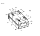
本発明によると、また、所定方向に配列された複数の単電池を備える組電池が提供される。前記単電池の各々は、正負の電極シートがセパレータを介して重ね合わされて捲回された電極体が容器に収容された構成を有する。前記複数の単電池は、前記電極体の軸に対して横方向に配列され、且つ該配列方向に荷重が加えられた状態で拘束されている。それら複数の単電池のうち少なくとも一つ(全部であってもよい。)は、ここに開示されるいずれかのリチウムイオン電池(ここに開示されるいずれかの方法で製造されたリチウムイオン電池であり得る。)である。かかる構成の組電池では、捲回電極体が軸の横方向から締め付けられている(すなわち、該電極体を構成する両電極シートおよびセパレータがそれらの積層方向に圧迫されている)ので、活物質層の端部における物質移動の重要性が特に大きい。したがって、ここに開示されるいずれかのリチウムイオン電池の構成を採用する効果が特によく発揮され得る。 According to the present invention, an assembled battery including a plurality of single cells arranged in a predetermined direction is also provided. Each of the single cells has a configuration in which an electrode body in which positive and negative electrode sheets are overlapped and wound via a separator is accommodated in a container. The plurality of unit cells are arranged in a direction transverse to the axis of the electrode body and are restrained in a state where a load is applied in the arrangement direction. At least one (or all) of the plurality of unit cells may be any of the lithium ion batteries disclosed herein (lithium ion batteries manufactured by any of the methods disclosed herein). It is possible.) In the assembled battery having such a configuration, the wound electrode body is clamped from the lateral direction of the shaft (that is, both the electrode sheets and the separator constituting the electrode body are pressed in the stacking direction thereof), so that the active material The importance of mass transfer at the end of the layer is particularly significant. Therefore, the effect of adopting any of the lithium ion battery configurations disclosed herein can be exhibited particularly well.
ここに開示されるリチウムイオン電池は、上述のように自己放電防止性に優れ、且つ良好な電池特性を示し得ることから、車両に搭載されるリチウムイオン電池として好適である。例えば、上記リチウムイオン電池の複数個を直列に接続した組電池の形態で、自動車等の車両のモータ(電動機)用の電源として好適に利用され得る。したがって本発明によると、ここに開示されるいずれかのリチウムイオン電池(ここに開示されるいずれかの方法により製造されたリチウムイオン電池であり得る)を備えた車両が提供される。かかる車両は、ここに開示されるいずれかの組電池を備えた車両であり得る。 The lithium ion battery disclosed here is suitable as a lithium ion battery mounted on a vehicle because it has excellent self-discharge prevention properties and can exhibit good battery characteristics as described above. For example, it can be suitably used as a power source for a motor (electric motor) of a vehicle such as an automobile, in the form of an assembled battery in which a plurality of the lithium ion batteries are connected in series. Thus, according to the present invention, there is provided a vehicle comprising any of the lithium ion batteries disclosed herein (which may be lithium ion batteries manufactured by any of the methods disclosed herein). Such a vehicle may be a vehicle including any of the assembled batteries disclosed herein.
以下、本発明の好適な実施形態を説明する。なお、本明細書において特に言及している事項以外の事柄であって本発明の実施に必要な事柄は、当該分野における従来技術に基づく当業者の設計事項として把握され得る。本発明は、本明細書に開示されている内容と当該分野における技術常識とに基づいて実施することができる。また、以下の図面において、同じ作用を奏する部材・部位には同じ符号を付して説明し、重複する説明は省略または簡略化することがある。 Hereinafter, preferred embodiments of the present invention will be described. Note that matters other than matters specifically mentioned in the present specification and necessary for the implementation of the present invention can be grasped as design matters of those skilled in the art based on the prior art in this field. The present invention can be carried out based on the contents disclosed in this specification and common technical knowledge in the field. Further, in the following drawings, members / parts having the same action are described with the same reference numerals, and overlapping descriptions may be omitted or simplified.
ここに開示される発明は、長尺シート状の負極集電体の表面に負極活物質層を有する負極シートと、長尺シート状の正極集電体の表面に正極活物質層を有する正極シートとを、長尺シート状のセパレータを介して重ね合わせて捲回してなる電極体を備え、上記負極活物質層の外表面に多孔質無機層を有する構成のリチウムオン電池、該リチウムイオン電池用の負極、該リチウムイオン電池を有する組電池(例えば、上記リチウムイオン電池を少なくとも一個含む複数個の単電池を直列に接続してなる組電池)、ならびにそれらの製造に広く適用され得る。リチウムイオン電池の外形は特に限定されず、例えば直方体状、扁平な角型形状、円筒状等の外形であり得る。 The invention disclosed herein includes a negative electrode sheet having a negative electrode active material layer on the surface of a long sheet-like negative electrode current collector, and a positive electrode sheet having a positive electrode active material layer on the surface of a long sheet-like positive electrode current collector A lithium-on battery comprising a porous inorganic layer on the outer surface of the negative electrode active material layer, and a lithium ion battery for the lithium ion battery The present invention can be widely applied to negative electrodes, assembled batteries having the lithium ion batteries (for example, assembled batteries in which a plurality of unit cells including at least one lithium ion battery are connected in series), and production thereof. The outer shape of the lithium ion battery is not particularly limited, and may be, for example, a rectangular parallelepiped shape, a flat rectangular shape, a cylindrical shape, or the like.
負極集電体としては、導電性の良好な金属からなるシート状部材を好ましく用いることができる。特に、銅(Cu)または銅を主成分とする合金(銅合金)製の負極集電体の使用が好ましい。負極集電体のサイズは特に限定されず、目的とするリチウムイオン電池の形状等に応じて適宜選択し得る。例えば、厚さ5μm〜30μm程度の金属箔を負極集電体として好ましく使用することができる。負極集電体の幅は例えば2cm〜15cm程度とすることができ、長さは例えば5cm〜1000cm程度とすることができる。 As the negative electrode current collector, a sheet-like member made of a metal having good conductivity can be preferably used. In particular, it is preferable to use a negative electrode current collector made of copper (Cu) or an alloy containing copper as a main component (copper alloy). The size of the negative electrode current collector is not particularly limited, and can be appropriately selected according to the shape of the target lithium ion battery. For example, a metal foil having a thickness of about 5 μm to 30 μm can be preferably used as the negative electrode current collector. The width of the negative electrode current collector can be, for example, about 2 cm to 15 cm, and the length can be, for example, about 5 cm to 1000 cm.
ここに開示される技術における負極シートは、かかる負極集電体の表面に、負極活物質を主成分とする層(負極活物質層)を有する。その負極活物質層は、負極集電体の長手方向に沿った少なくとも一方の縁を帯状に残して、典型的には負極集電体の両サイドの表面(両面)に形成されている。上記帯状部分(負極集電体上に負極活物質層が形成されていない部分、すなわち負極活物質層非形成部)は、後述のように、上記負極シートを外部接続用の負極端子に電気的に接続する部位(集電部)として利用され得る。 The negative electrode sheet in the technique disclosed herein has a layer (negative electrode active material layer) containing a negative electrode active material as a main component on the surface of the negative electrode current collector. The negative electrode active material layer is typically formed on the surfaces (both sides) of both sides of the negative electrode current collector, leaving at least one edge along the longitudinal direction of the negative electrode current collector in a strip shape. The band-like portion (the portion where the negative electrode active material layer is not formed on the negative electrode current collector, that is, the portion where the negative electrode active material layer is not formed) is electrically connected to the negative electrode terminal for external connection as described later. It can be used as a part (current collector) connected to.
上記負極活物質層非形成部は、負極集電体の両面の重複する位置(好ましくは、両面のほぼ同じ位置)に設けられていることが好ましい。リチウムイオン電池のエネルギー密度等の観点から、負極集電体の長手方向に沿った一方の縁には両面のほぼ同じ位置に負極活物質層非形成部が設けられ、該集電体の長手方向に沿った他方の縁には両面ともほぼ端まで負極活物質層が形成された形態(すなわち、長手方向に沿った一方の縁にのみ活物質層非形成部が設けられた形態)の負極シートを好ましく採用し得る。 The negative electrode active material layer non-forming portion is preferably provided at a position where both surfaces of the negative electrode current collector overlap (preferably, substantially the same position on both surfaces). From the viewpoint of the energy density of the lithium ion battery, a negative electrode active material layer non-forming portion is provided at one edge along the longitudinal direction of the negative electrode current collector at substantially the same position on both surfaces, and the longitudinal direction of the current collector A negative electrode sheet in a form in which a negative electrode active material layer is formed on the other edge along the both sides almost to the end (that is, a form in which an active material layer non-forming portion is provided only on one edge along the longitudinal direction) Can be preferably employed.
上記負極活物質層非形成部は、この負極シートを用いてなる捲回電極体において、少なくともその捲回の二周以上に亘る長さに連続して形成されていることが好ましい。好ましい一態様では、負極シートの全長に亘って負極活物質層非形成部が形成されている。負極活物質層非形成部の幅は、電極体の形状や集電部の接続構造等に応じて適宜設定し得る。通常は、5mm〜50mm(例えば10mm〜30mm)程度の幅とすることが適当である。 The negative electrode active material layer non-formation part is preferably formed continuously in a wound electrode body using the negative electrode sheet for a length of at least two turns of the wound. In a preferred embodiment, the negative electrode active material layer non-forming portion is formed over the entire length of the negative electrode sheet. The width of the negative electrode active material layer non-forming portion can be appropriately set according to the shape of the electrode body, the connection structure of the current collector portion, and the like. Usually, a width of about 5 mm to 50 mm (for example, 10 mm to 30 mm) is appropriate.
負極活物質としては、Liイオンを可逆的に吸蔵および放出可能な材料が用いられ、一般的なリチウムイオン電池の負極活物質として機能し得ることが知られている種々の負極活物質から適当なものを採用することができる。ここに開示される技術における好適な負極活物質として炭素材料が例示される。少なくとも一部にグラファイト構造(層状構造)を含む粒子状の炭素材料(カーボン粒子)の使用が好ましい。いわゆる黒鉛質のもの(グラファイト)、難黒鉛化炭素質のもの(ハードカーボン)、易黒鉛化炭素質のもの(ソフトカーボン)、これらを組み合わせた構造を有するもののいずれの炭素材料も使用可能である。例えば、天然黒鉛、メソカーボンマイクロビーズ(MCMB)、高配向性グラファイト(HOPG)等を用いることができる。 As the negative electrode active material, a material capable of reversibly occluding and releasing Li ions is used, and various negative electrode active materials known to function as a negative electrode active material of a general lithium ion battery are used. Things can be adopted. A carbon material is illustrated as a suitable negative electrode active material in the technique disclosed here. It is preferable to use a particulate carbon material (carbon particles) containing a graphite structure (layered structure) at least partially. Any carbon material of a so-called graphitic material (graphite), non-graphitizable carbon material (hard carbon), graphitizable carbon material (soft carbon), or a combination of these can be used. . For example, natural graphite, mesocarbon microbeads (MCMB), highly oriented graphite (HOPG), etc. can be used.
上記負極活物質の性状としては、例えば、平均粒径が凡そ5μm〜50μmの粒子状が好ましい。なかでも、平均粒径が凡そ5μm〜15μm(例えば凡そ8μm〜12μm)のカーボン粒子の使用が好ましい。このように比較的小粒径のカーボン粒子は、単位体積当たりの表面積が大きいことから、より急速充放電(例えば高出力放電)に適した負極活物質となり得る。したがって、かかる負極活物質を有するリチウムイオン電池は、例えば車両搭載用のリチウムイオン電池として好適に利用され得る。また、上記のように比較的小粒径のカーボン粒子は、より大きな粒子を用いる場合に比べて充放電に伴う個々のカーボン粒子の体積変動が小さいことから、負極活物質層全体として該体積変動をよりよく緩衝(吸収)し得る。このことは、負極活物質層上に形成された多孔質無機層の耐久性(剥離等の防止)の観点から有利である。 As the properties of the negative electrode active material, for example, particles having an average particle size of about 5 μm to 50 μm are preferable. Among them, it is preferable to use carbon particles having an average particle diameter of about 5 μm to 15 μm (for example, about 8 μm to 12 μm). Thus, carbon particles having a relatively small particle size have a large surface area per unit volume, and thus can be a negative electrode active material suitable for more rapid charge / discharge (for example, high power discharge). Therefore, a lithium ion battery having such a negative electrode active material can be suitably used, for example, as a lithium ion battery for mounting on a vehicle. In addition, as described above, the carbon particle having a relatively small particle size has a smaller volume variation of the individual carbon particles due to charge / discharge compared to the case of using a larger particle. Can be better buffered (absorbed). This is advantageous from the viewpoint of durability (prevention of peeling and the like) of the porous inorganic layer formed on the negative electrode active material layer.
上記負極活物質層は、例えば、負極活物質(好ましくは粒子状、例えばカーボン粒子)を適当な溶媒に分散させた液状組成物(典型的にはペーストまたはスラリー状の組成物)を負極集電体に付与し、該組成物(負極活物質層形成用組成物)を乾燥させることにより好ましく作製され得る。上記溶媒(負極活物質の分散媒)としては、水、有機溶媒およびこれらの混合溶媒のいずれも使用可能である。例えば、負極活物質層形成用組成物の溶媒として水系溶媒(水、または水を主成分とする混合溶媒)を好ましく採用することができる。 The negative electrode active material layer is formed by, for example, collecting a liquid composition (typically a paste or slurry composition) in which a negative electrode active material (preferably in the form of particles, for example, carbon particles) is dispersed in a suitable solvent. It can preferably be prepared by applying to a body and drying the composition (a composition for forming a negative electrode active material layer). As the solvent (dispersion medium of the negative electrode active material), any of water, an organic solvent, and a mixed solvent thereof can be used. For example, an aqueous solvent (water or a mixed solvent containing water as a main component) can be preferably used as the solvent for the composition for forming a negative electrode active material layer.
上記負極活物質層形成用組成物は、負極活物質および上記溶媒のほかに、一般的なリチウムイオン電池用負極の製造において負極活物質層の形成に用いられる液状組成物に配合され得る一種または二種以上の材料を必要に応じて含有することができる。そのような材料の例として、バインダ(結着剤)および/または流動性調整剤として機能し得るポリマーが挙げられる。例えば、ポリフッ化ビニリデン(PVDF)、ポリテトラフルオロエチレン(PTFE)、ポリフッ化ビニリデン−ヘキサフルオロプロピレン共重合体(PVDF−HFP)、スチレンブタジエンゴム(SBR)、カルボキシメチルセルロース(CMC)等のポリマーから適宜選択される一種または二種以上を、上記バインダおよび/または流動性調整剤(典型的には粘度調整剤、例えば増粘剤)として好適に使用することができる。 In addition to the negative electrode active material and the solvent, the negative electrode active material layer forming composition is a kind or a liquid composition used for forming a negative electrode active material layer in the production of a general negative electrode for a lithium ion battery. Two or more kinds of materials can be contained as required. Examples of such materials include polymers that can function as binders and / or fluidity modifiers. For example, as appropriate from polymers such as polyvinylidene fluoride (PVDF), polytetrafluoroethylene (PTFE), polyvinylidene fluoride-hexafluoropropylene copolymer (PVDF-HFP), styrene butadiene rubber (SBR), carboxymethyl cellulose (CMC), etc. One or two or more selected ones can be suitably used as the binder and / or fluidity modifier (typically a viscosity modifier such as a thickener).
特に限定するものではないが、負極活物質層形成用組成物の固形分(不揮発分、すなわち該組成物全体に占める負極活物質層形成成分の質量割合;以下、NVと表記することもある。)は、例えば凡そ40%〜60%程度とすることが適当である。また、固形分(負極活物質層形成成分)に占める負極活物質の質量割合は、例えば凡そ85%以上(典型的には凡そ85%〜99.9%)とすることができ、凡そ90%〜99%とすることが好ましく、凡そ95%〜99%とすることがより好ましい。 Although not particularly limited, the solid content of the negative electrode active material layer forming composition (nonvolatile content, that is, the mass ratio of the negative electrode active material layer forming component in the entire composition; hereinafter, sometimes referred to as NV. ) Is suitably about 40% to 60%, for example. The mass ratio of the negative electrode active material in the solid content (negative electrode active material layer forming component) can be, for example, about 85% or more (typically about 85% to 99.9%), and about 90%. It is preferable to set it to -99%, and it is more preferable to set it to about 95%-99%.
かかる負極活物質層形成用組成物を負極集電体に付与するにあたっては、従来公知の方法と同様の技法を適宜採用することができる。例えば、適当な塗布装置(グラビアコーター、スリットコーター、ダイコーター、コンマコーター等)を使用して所定量の上記負極活物質層形成用組成物を集電体表面に塗布するとよい。このとき、上記負極活物質層非形成部に対応する箇所を残して上記組成物を付与することにより、所定の範囲に負極活物質層を形成することができる。あるいは、いったん形成した負極活物質層の所定範囲を負極集電体から除去することで負極活物質層非形成部を形成してもよい。これらの手法を組み合わせて用いてもよい。 In applying such a composition for forming a negative electrode active material layer to a negative electrode current collector, a technique similar to a conventionally known method can be appropriately employed. For example, a predetermined amount of the composition for forming a negative electrode active material layer may be applied to the surface of the current collector using an appropriate coating device (such as a gravure coater, slit coater, die coater, or comma coater). At this time, the negative electrode active material layer can be formed in a predetermined range by applying the composition leaving a portion corresponding to the negative electrode active material layer non-forming portion. Or you may form a negative electrode active material layer non-formation part by removing the predetermined range of the negative electrode active material layer once formed from the negative electrode collector. You may use combining these methods.
負極活物質層形成用組成物の塗布量(集電体の単位面積当たりの塗布量)は特に限定されず、負極シートおよび電池の形状や目標性能等に応じて適宜異なり得る。好ましい一態様では、箔状集電体(例えば、厚さ5μm〜30μm程度の金属箔(銅箔等)を好ましく用いることができる。)の両面に上記組成物を、NV換算の塗布量(すなわち、乾燥後の質量)が両面合わせて凡そ5〜20mg/cm2程度となるように塗布するとよい。The coating amount of the negative electrode active material layer forming composition (the coating amount per unit area of the current collector) is not particularly limited, and may be appropriately varied depending on the shape, target performance, and the like of the negative electrode sheet and the battery. In a preferred embodiment, the composition is applied to both sides of a foil-like current collector (for example, a metal foil (such as a copper foil) having a thickness of about 5 μm to 30 μm can be preferably used) in an NV conversion amount (that is, The weight after drying is preferably about 5 to 20 mg / cm 2 when the both surfaces are combined.
塗布後、適当な乾燥手段で塗布物を乾燥し、必要に応じてプレスすることにより、負極集電体の表面に負極活物質層を形成することができる。特に限定するものではないが、上記負極活物質層の密度は例えば凡そ1.1〜1.5g/cm3程度であり得る。該負極活物質層の密度が凡そ1.1〜1.3g/cm3程度であってもよい。かかる密度を有する負極活物質層が形成されるように上記プレスの条件を設定するとよい。なお、プレス方法としては、ロールプレス法、平板プレス法等の従来公知の各種プレス方法を適宜採用することができる。After the coating, the coated material is dried by an appropriate drying means, and pressed as necessary, whereby a negative electrode active material layer can be formed on the surface of the negative electrode current collector. Although not particularly limited, the density of the negative electrode active material layer may be, for example, about 1.1 to 1.5 g / cm 3 . The density of the negative electrode active material layer may be about 1.1 to 1.3 g / cm 3 . The press conditions may be set so that a negative electrode active material layer having such a density is formed. In addition, as a press method, conventionally well-known various press methods, such as a roll press method and a flat plate press method, can be employ | adopted suitably.
ここに開示される技術における負極シートでは、上記負極活物質層の外表面に、該活物質層の平面部から上記活物質層非形成部側の端部を回り込んで負極集電体表面に至る多孔質無機層が設けられている。ここで、負極活物質層の「平面部」とは、該活物質層が面状に、好適にはほぼ一様な厚さで広がっている部分をいう。典型的には、負極活物質層と正極活物質とが重ね合わせて配置される部分は、該負極活物質層の平面部に含まれる。好ましい一態様では、上記平面部の全範囲に亘って連続的に多孔質無機層が設けられている。 In the negative electrode sheet in the technology disclosed herein, the edge of the active material layer non-formation part side is turned around from the flat part of the active material layer to the outer surface of the negative electrode active material layer to the negative electrode current collector surface. A porous inorganic layer is provided. Here, the “planar portion” of the negative electrode active material layer refers to a portion where the active material layer spreads in a planar shape, preferably with a substantially uniform thickness. Typically, a portion where the negative electrode active material layer and the positive electrode active material are arranged so as to overlap each other is included in the flat portion of the negative electrode active material layer. In a preferred embodiment, the porous inorganic layer is continuously provided over the entire range of the planar portion.
一方、負極活物質層の「活物質層非形成部側の端部」とは、負極活物質層のうち活物質層非形成部との境界に沿う端部をいい、典型的には負極活物質層の平面部に続く部分となっている。この活物質層非形成部側端部は、例えば、負極活物質層と活物質層非形成部との境界から該負極活物質層の内側に向かう幅2mmの範囲であり得る。この活物質層非形成部側端部は、少なくともその一部が正極活物質層からはみ出すように配置されることが好ましい。 On the other hand, the “end on the active material layer non-formation part side” of the negative electrode active material layer refers to an end along the boundary with the active material layer non-formation part of the negative electrode active material layer. It is the part that follows the flat part of the material layer. This active material layer non-formation part side edge part can be the range of width 2mm which goes to the inner side of this negative electrode active material layer from the boundary of a negative electrode active material layer and an active material layer non-formation part, for example. The end portion on the active material layer non-forming part side is preferably arranged so that at least a part thereof protrudes from the positive electrode active material layer.
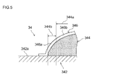
図3〜5に示されるように、ここに開示される負極シート34の典型的な構成例では、多孔質無機層346が、負極活物質層344の平面部344aから負極活物質層非形成部側の端部344bに至り、さらに端部344bを負極活物質層344の厚み沿いに回り込んで負極集電体342の表面に到達するまで連続して設けられている。すなわち、負極活物質層344の端部344bは、絶縁性の多孔質無機層346によってすっかり覆われている。かかる構成によると、負極活物質層344の負極活物質層非形成部側の端部344bと対極(正極シート)との間で微小短絡が発生する事象を高度に防止することができる。なお、図3は、捲回電極体30を径方向(正負極シートおよびセパレータの積層方向)に切断した断面の一部を拡大して示す模式的断面図である。
As shown in FIGS. 3 to 5, in the typical configuration example of the
ここに開示される技術において、多孔質無機層に含まれる細孔(空隙)の平均孔径は、該無機層の形成目的(電池の信頼性向上、より具体的には内部短絡の防止等)が適切に達成され、かつ所望の電池特性が確保されるように設定すればよく、特に限定されない。例えば、平均孔径が凡そ0.01μm〜10μm(より好ましくは凡そ0.1μm〜4μm)の範囲にある多孔質無機層が好ましい。上記平均孔径は、市販の水銀ポロシメータ等を用いて測定することができる。 In the technique disclosed herein, the average pore diameter of pores (voids) contained in the porous inorganic layer is determined by the purpose of forming the inorganic layer (improving battery reliability, more specifically, preventing internal short circuit). What is necessary is just to set so that it may achieve suitably and a desired battery characteristic may be ensured, and it does not specifically limit. For example, a porous inorganic layer having an average pore diameter in the range of about 0.01 μm to 10 μm (more preferably about 0.1 μm to 4 μm) is preferable. The average pore diameter can be measured using a commercially available mercury porosimeter or the like.
ここに開示される負極シートの典型的な態様では、多孔質無機層のうち負極活物質層の活物質層非形成部側端部を覆う部分(第1部分)の気孔率Pa[体積%]が、上記活物質層の幅の中央部を覆う部分(第2部分)の気孔率Pb[体積%]よりも小さい。このことによって、短絡防止性と物質移動性とを高レベルで両立させることができる。すなわち、負極活物質層の上記活物質層非形成部側端部は上述のように異物が溜まりやすい箇所に近接するため、この部分を覆う上記第1部分の気孔率Paを相対的に低くすることにより、該端部における短絡防止性を高めることができる。一方、負極活物質の平面部(負極活物質層の幅中央部は該平面部に含まれる。)では、上記端部に比べて、上記異物に起因する微小短絡が起こりにくい。このことを利用して、上記第2部分の気孔率Pbを相対的に高くすることにより、負極活物質層と外部との物質移動性(電解液浸透性、Liイオン移動性等)を高めることができる。かかる構成によると、負極シート全体として、短絡防止性と電池性能とを高レベルで両立させることができる。 In a typical aspect of the negative electrode sheet disclosed herein, the porosity Pa [volume%] of the portion (first portion) covering the active material layer non-forming portion side end portion of the negative electrode active material layer in the porous inorganic layer. However, it is smaller than the porosity Pb [volume%] of the portion (second portion) covering the central portion of the width of the active material layer. This makes it possible to achieve both a short circuit prevention property and a mass mobility at a high level. That is, since the end of the negative electrode active material layer on the side where the active material layer is not formed is close to the portion where foreign matter is likely to accumulate as described above, the porosity Pa of the first portion covering this portion is relatively lowered. Thereby, the short-circuit prevention property in this edge part can be improved. On the other hand, in the flat part of the negative electrode active material (the central part of the width of the negative electrode active material layer is included in the flat part), a micro short circuit caused by the foreign matter is less likely to occur compared to the end part. Utilizing this fact, the mobility of the negative electrode active material layer and the outside (electrolyte permeability, Li ion mobility, etc.) is enhanced by relatively increasing the porosity Pb of the second part. Can do. According to such a configuration, it is possible to achieve both a short-circuit prevention property and battery performance at a high level as the whole negative electrode sheet.
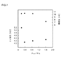
上記気孔率の比Pa/Pbは、典型的には凡そ0.25以上1未満であり、好ましくは凡そ0.3以上0.9以下である。Pa/Pbが小さすぎると、上記第1部分を通じての物質移動性が低くなりすぎ、これにより電池の内部抵抗が上昇しがちとなることがあり得る。 The porosity ratio Pa / Pb is typically about 0.25 to less than 1, and preferably about 0.3 to 0.9. If Pa / Pb is too small, the mass mobility through the first part may be too low, which tends to increase the internal resistance of the battery.
ここに開示される構成により実現され得る他の効果として、電池の製造過程において電極体に電解液を浸透させる際、多孔質無機層の気孔率が該無機層の全体に亘って均等である場合に比べて、該電解液の浸透に要する時間のばらつきを低減し得ることが挙げられる。このことは、電池の生産性向上、品質安定性向上等の観点から好ましい。 As another effect that can be realized by the configuration disclosed herein, when the electrolyte solution is infiltrated into the electrode body in the battery manufacturing process, the porosity of the porous inorganic layer is uniform throughout the inorganic layer. Compared to the above, it is possible to reduce variation in time required for the penetration of the electrolytic solution. This is preferable from the viewpoint of improving battery productivity and quality stability.
特に限定するものではないが、上記気孔率Paは、例えば凡そ70体積%以下(典型的には10〜70体積%)とすることができる。好ましい一態様では、Paを凡そ20〜65体積%(例えば凡そ35〜65体積%)の範囲とする。このことによって、上記異物に起因する微小短絡を高度に防止するともに、その微小短絡防止性を顕著に損なわない範囲で、上記無機層の第1部分の物質移動性(Liイオン移動性、電解液浸透性等)を高めることができる。したがって、負極シート全体として、短絡防止性と電池性能とをより高いレベルで両立させることができる。 Although not particularly limited, the porosity Pa can be, for example, about 70% by volume or less (typically 10 to 70% by volume). In a preferred embodiment, Pa is in the range of about 20 to 65% by volume (for example, about 35 to 65% by volume). As a result, the micro short circuit caused by the foreign matter is highly prevented, and the mass mobility (Li ion mobility, electrolyte solution) of the first portion of the inorganic layer is within a range in which the micro short circuit prevention property is not significantly impaired. Penetrability and the like). Therefore, as a whole negative electrode sheet, it is possible to achieve both short-circuit prevention and battery performance at a higher level.
上記第1部分の気孔率Paが小さすぎると、該第1部分を通じて負極活物質層への上記第1部分の物質移動性が低くなることから、電池過程において電極体に電解液を浸透させる際、該浸透に要する時間が長くなって電池の生産性が低下しがちである。また、電解液の浸透が不十分な状態(例えば、負極活物質層の一部に電解液が浸透していない箇所が残った状態)で初期充電を行うと、電解液が浸透した箇所としていない箇所とで、負極活物質層の表面状態(例えば、SEI(Solid Electrolyte Interface)の生成の有無、その生成量(膜厚)、SEIの組成や性状等)に差異が生じ、このことによって電池性能のばらつきが生じ得る。一方、Paが大きすぎると、負極活物質層の端部における短絡防止性(例えば、後述する膜抵抗の低下として把握され得る。)が低下しがちとなることがある。 When the porosity Pa of the first part is too small, the mass mobility of the first part to the negative electrode active material layer is lowered through the first part. Therefore, when the electrolyte solution penetrates into the electrode body in the battery process The time required for the penetration tends to be long, and the productivity of the battery tends to decrease. Moreover, when the initial charge is performed in a state where the electrolyte solution is not sufficiently penetrated (for example, a portion where the electrolyte solution does not penetrate into a part of the negative electrode active material layer), the location where the electrolyte solution penetrates is not considered. Depending on the location, the surface state of the negative electrode active material layer (for example, whether or not SEI (Solid Electrolyte Interface) is generated, its generation amount (film thickness), SEI composition and properties, etc.) is different, and this results in battery performance. Variations can occur. On the other hand, when Pa is too large, short-circuit prevention at the end of the negative electrode active material layer (for example, it can be grasped as a decrease in film resistance described later) tends to decrease.
また、多孔質無機層の第2部分の気孔率Pbは、第1部分の気孔率Paよりも小さくなる範囲で(すなわち、Pa/Pb<1を満たす範囲で)、適宜設定することができる。例えば、Pbを凡そ25〜90体積%とすることができ、通常は凡そ30〜80体積%(例えば凡そ40〜70体積%)とすることが好ましい。 Further, the porosity Pb of the second portion of the porous inorganic layer can be appropriately set within a range smaller than the porosity Pa of the first portion (that is, within a range satisfying Pa / Pb <1). For example, Pb can be about 25 to 90% by volume, and usually about 30 to 80% by volume (for example, about 40 to 70% by volume) is preferable.
多孔質無機層の気孔率は、該無機層の目付(単位面積当たりの質量)を該無機層の厚みで割ることによって算出することができる。ここで、多孔質無機層の目付は、後述するように、蛍光X線分析、無機層の形成に伴う質量増加分の測定、等の手法により把握することができる。また、多孔質無機層の厚みは、市販の膜圧測定器(ロータリーキャリパー方式、触針式等の、各種方式の測定器であり得る。)を用いて把握することができる。あるいは負極シート断面の電子顕微鏡観察により多孔質無機層の厚みを求めてもよい。 The porosity of the porous inorganic layer can be calculated by dividing the basis weight (mass per unit area) of the inorganic layer by the thickness of the inorganic layer. Here, the basis weight of the porous inorganic layer can be grasped by techniques such as fluorescent X-ray analysis and measurement of mass increase accompanying the formation of the inorganic layer, as will be described later. Moreover, the thickness of the porous inorganic layer can be grasped using a commercially available membrane pressure measuring device (which can be a measuring device of various types such as a rotary caliper method and a stylus type). Or you may obtain | require the thickness of a porous inorganic layer by electron microscope observation of the negative electrode sheet cross section.
なお、通常は、「負極活物質層の幅の中央部における無機層の気孔率Pb」を、負極活物質層の幅のちょうど中央における気孔率で代表させる(すなわち、この部分について測定した気孔率の値をPbとして採用する)ことができる。また、「活物質層非形成部側の端部に形成された無機層の気孔率Pa」は、負極活物質層と活物質層非形成部との境界から内側に向かう幅2mmの範囲のうち概ね中央部(例えば、上記境界から1mm内側の部分)における気孔率で代表させることができる。
Normally, the “porosity Pb of the inorganic layer at the center of the width of the negative electrode active material layer” is represented by the porosity at the exact center of the width of the negative electrode active material layer (that is, the porosity measured for this portion). Can be adopted as Pb). Further, the “porosity Pa of the inorganic layer formed at the end portion on the active material layer non-forming portion side” is within a range of 2 mm in width from the boundary between the negative electrode active material layer and the active material layer non-forming portion to the inside. It can be represented by the porosity in a generally central portion (for example, a
ここに開示される負極シートは、負極活物質層の上記活物質層非形成部側端部に形成された無機層(第1部分)の目付Waと、該活物質層の幅の中央部における無機層(第2部分)の目付Wbとの質量比Wa/Wbが、例えば凡そ0.5〜1.2となる態様で好ましく実施することができる。各部における無機層(例えば、アルミナ粒子を主成分とする無機層)の目付は、例えば、一般的な蛍光X線分析により把握することができる。例えば、使用する無機粒子の材質に合わせて目付量と蛍光X線強度との相関を調べる予備実験を行い、その結果を適用することによって多孔質無機層の目付を求めることができる。あるいは、多孔質無機層の形成前後における質量変化から該無機層の目付を求めてもよい。 The negative electrode sheet disclosed here has a weight per unit area Wa of the inorganic layer (first portion) formed at the end of the negative electrode active material layer on the side where the active material layer is not formed, and a central portion of the width of the active material layer. It can be preferably implemented in an embodiment in which the mass ratio Wa / Wb of the inorganic layer (second portion) to the basis weight Wb is, for example, about 0.5 to 1.2. The basis weight of the inorganic layer (for example, an inorganic layer containing alumina particles as a main component) in each part can be grasped by, for example, general fluorescent X-ray analysis. For example, the basis weight of the porous inorganic layer can be obtained by conducting a preliminary experiment for examining the correlation between the basis weight and the fluorescent X-ray intensity according to the material of the inorganic particles to be used, and applying the result. Or you may obtain | require the fabric weight of this inorganic layer from the mass change before and behind formation of a porous inorganic layer.
負極活物質層を覆う無機層は、該活物質層へのLiイオンの出入りに対する抵抗となる。このため、Wa/Wbが小さすぎると、上記端部の抵抗が局所的に低くなって、該端部への電流集中(充放電における反応ムラ)が起こりやすくなる。かかる電流集中(すなわち電流密度の偏り)は、電池の劣化を促進する要因となり得る。特に、車両の動力源として用いられるリチウムイオン電池のようにハイレート充電を伴う使用形態では、上記電流密度の偏りが大きくなりやすいことから、電解液の分解等の副反応が促進されやすい。このように大きく偏った電流密度で充電を繰り返すと、電池の容量低下が進行しやすい。一方、Wa/Wbが大きすぎると、上記端部においてLiイオンの出入りに対する抵抗が局所的に高くなる。このため上記端部のLiイオン受入性が低下し、該端部においてLiが析出しやすくなる。ハイレート充電を伴う使用形態では特にLiが析出しやすい。かかるLiの析出は、電池の容量を低下させる要因となり得る。Wa/Wbを上記範囲とすることにより、負極活物質の端部を多孔質無機層ですっかり覆って微小短絡の発生を高度に防止しながら、電池の耐久性(例えば、充放電を繰り返しても容量の低下が少ないこと)を高レベルに維持することができる。 The inorganic layer covering the negative electrode active material layer provides resistance to the entry and exit of Li ions into the active material layer. For this reason, if Wa / Wb is too small, the resistance of the end portion is locally reduced, and current concentration (reaction unevenness in charge / discharge) easily occurs at the end portion. Such current concentration (that is, current density bias) can be a factor for promoting deterioration of the battery. In particular, in a usage pattern involving high-rate charging, such as a lithium ion battery used as a power source for vehicles, the current density bias tends to increase, so that side reactions such as decomposition of the electrolytic solution are easily promoted. If charging is repeated at such a greatly biased current density, the battery capacity tends to decrease. On the other hand, if Wa / Wb is too large, the resistance to the entry and exit of Li ions locally increases at the end. For this reason, the Li ion acceptability at the end is lowered, and Li is likely to precipitate at the end. Li is likely to precipitate particularly in a usage pattern involving high-rate charging. Such deposition of Li can be a factor of reducing the capacity of the battery. By setting Wa / Wb in the above range, the end of the negative electrode active material is completely covered with a porous inorganic layer to prevent the occurrence of micro-shorts, and the durability of the battery (for example, repeated charge / discharge) It is possible to maintain a high level of reduction in capacity).
好ましい一態様では、多孔質無機層の第1部分と第2部分との質量比Wa/Wbが凡そ1未満の範囲にある(すなわちWa/Wb<1。典型的には0.5≦Wa/Wb<1)。ここに開示される技術では、多孔質無機層の第1部分が第2部分よりも低気孔率であることから、Wa/Wbが1未満であれば、通常は、第1部分の厚みが第2部分の厚みよりも小さくなる。このように、負極活物質層の幅中央部(典型的には、該幅中央部を含む平面部)に比べて端部の多孔質無機層(第1部分)の厚みが相対的に小さいと、正負の電極シートおよびセパレータがより緊密に捲回された捲回電極体が得られやすい。このことは、電池のエネルギー密度を高める上で有利である。また、多孔質無機層の第1部分の厚みを第2部分に比べて小さくすることは、例えば該無機層の厚みが全範囲に亘って均等である場合に比べて、上記活物質層非形成部側端部から電極体の軸方向内部への(典型的には、幅中央部に向けての)物質移動性を高める上でも有利である。 In a preferred embodiment, the mass ratio Wa / Wb between the first portion and the second portion of the porous inorganic layer is in the range of less than about 1 (ie, Wa / Wb <1; typically 0.5 ≦ Wa / Wb <1). In the technology disclosed herein, the first portion of the porous inorganic layer has a lower porosity than the second portion. Therefore, if Wa / Wb is less than 1, the thickness of the first portion is usually the first. It is smaller than the thickness of the two parts. Thus, when the thickness of the porous inorganic layer (first portion) at the end is relatively smaller than the width central portion of the negative electrode active material layer (typically, the flat portion including the width central portion). It is easy to obtain a wound electrode body in which the positive and negative electrode sheets and the separator are wound more closely. This is advantageous in increasing the energy density of the battery. Further, reducing the thickness of the first portion of the porous inorganic layer compared to the second portion means that the active material layer is not formed as compared with, for example, the case where the thickness of the inorganic layer is uniform over the entire range. It is also advantageous for enhancing the mass mobility from the part side end part to the inside of the electrode body in the axial direction (typically toward the center of the width).
ここに開示される技術では、多孔質無機層の第1部分の気孔率を相対的に低くしているので、該第1部分における微小短絡防止性(後述する膜抵抗により把握され得る。)を所望のレベルに維持しつつ、該第1部分の厚みをより小さくすることができる。ここに開示される技術の好ましい一態様によれば、多孔質無機層がPa/Pb<1(好ましくは0.25≦Pa/Pb≦0.95、例えば0.3≦Pa/Pb≦0.9)を満たすことと、該無機層がWa/Wb<1(好ましくは0.5≦Wa/Wb<1)を満たすこととの相乗効果によって、上記端部を無機層ですっかり覆うことに伴って生じ得る弊害を、より高度に防止または抑制することができる。例えば、微小短絡防止性と他の電池性能とを、より高レベルでバランスさせた高性能な電池が実現され得る。 In the technique disclosed here, the porosity of the first portion of the porous inorganic layer is relatively low, so that the short-circuit prevention property (which can be grasped by the membrane resistance described later) in the first portion. The thickness of the first portion can be further reduced while maintaining the desired level. According to a preferred aspect of the technology disclosed herein, the porous inorganic layer has Pa / Pb <1 (preferably 0.25 ≦ Pa / Pb ≦ 0.95, for example, 0.3 ≦ Pa / Pb ≦ 0. 9) With the synergistic effect of satisfying the above and the inorganic layer satisfying Wa / Wb <1 (preferably 0.5 ≦ Wa / Wb <1), the edge is completely covered with the inorganic layer. The adverse effects that may occur can be prevented or suppressed to a higher degree. For example, a high-performance battery in which the micro short-circuit prevention property and other battery performance are balanced at a higher level can be realized.
好ましいWbの範囲は、多孔質無機層の組成や電池の構成等により異なり得るが、通常は0.3〜3mg/cm2(例えば0.5〜1mg/cm2)程度とすることが適当である。Wbが小さすぎると十分な微小短絡防止効果が得られ難くなる場合がある。Wbが大きすぎると電池の内部抵抗が上昇しやすくなる。The preferred range of Wb can may differ by configuration of the composition and the battery of the porous inorganic layer, generally suitable to be 0.3 to 3 mg / cm 2 (e.g. 0.5 to 1 mg / cm 2) degree is there. If Wb is too small, it may be difficult to obtain a sufficient effect of preventing a short circuit. If Wb is too large, the internal resistance of the battery tends to increase.
なお、通常は、「負極活物質層の幅の中央部における無機層の目付Wb」を、負極活物質層の幅のちょうど中央における目付量で代表させる(すなわち、この目付量の値をWbとして採用する)ことができる。また、「活物質層非形成部側の端部に形成された無機層の目付Wa」は、負極活物質層と活物質層非形成部との境界から内側に向かう幅2mmの範囲のうち概ね中央部(例えば、上記境界から1mm内側の部分)における目付量で代表させることができる。 Normally, “the weight per unit area Wb of the inorganic layer at the center of the width of the negative electrode active material layer” is represented by the basis weight at the exact center of the width of the negative electrode active material layer (that is, the value of the basis weight is defined as Wb). Can be adopted). Further, the “weight Wa of the inorganic layer formed at the end portion on the active material layer non-forming portion side” is roughly within a range of 2 mm in width from the boundary between the negative electrode active material layer and the active material layer non-forming portion to the inside. The weight per unit area can be represented by the weight per unit area (for example, 1 mm inside from the boundary).
好ましい一態様では、負極活物質層と活物質層非形成部との境界からさらに外側まで(すなわち、活物質層非形成部の少なくとも一部を覆って)多孔質無機層が広がっている。この広がりの大きさは、例えば、上記境界から外側に幅3mm以下(例えば1mm〜2mm)の範囲とすることができる。かかる態様によると、微小短絡の発生をより高度に防止することができる。活物質層非形成部上に設けられる多孔質無機層の厚みは特に限定されないが、通常は、0.5μm以上(好ましくは1μm以上)であって負極活物質層の厚み以下とすることが適当である。また、特に限定するものではないが、通常は、負極活物質層の幅の中央部における多孔質無機層の厚みを凡そ0.5μm〜10μm(例えば1μm〜6μm)とすることが適当である。 In a preferred embodiment, the porous inorganic layer extends from the boundary between the negative electrode active material layer and the active material layer non-forming portion to the outside (that is, covering at least part of the active material layer non-forming portion). The size of the spread can be, for example, a range of 3 mm or less (for example, 1 mm to 2 mm) from the boundary to the outside. According to this aspect, the occurrence of a micro short circuit can be prevented to a higher degree. The thickness of the porous inorganic layer provided on the active material layer non-forming part is not particularly limited, but is usually 0.5 μm or more (preferably 1 μm or more) and less than the thickness of the negative electrode active material layer. It is. Although not particularly limited, it is usually appropriate that the thickness of the porous inorganic layer at the central portion of the width of the negative electrode active material layer is about 0.5 μm to 10 μm (for example, 1 μm to 6 μm).
なお、長手方向に沿った一方の縁にのみ活物質層非形成部が設けられた形態の負極シートの場合、上記一方の縁とは反対側の端では、負極活物質層の端面が多孔質無機層で覆われていてもよく、覆われていなくてもよい。ここに開示されるリチウムイオン電池を構成する負極シートとしては、該負極シートの生産性等の観点から、図3に示す例のように、活物質層非形成部342aとは反対側の端面344cには多孔質無機層346が設けられていない(換言すれば、負極活物質層344の厚みに沿う端面が露出している)態様の負極シート34を好ましく採用し得る。かかる態様の負極シートは、例えば、目的とする負極シートの二倍の幅を有する負極集電体に、該集電体の長手方向に沿う両縁を帯状に残して負極活物質層を形成し、さらに該活物質層の上から多孔質無機層を形成した後に幅中央で裁断する(スリットする)ことにより、本発明に係るリチウムイオン電池の負極シートを効率よく製造することができる。
In the case of a negative electrode sheet in which an active material layer non-forming portion is provided only on one edge along the longitudinal direction, the end face of the negative electrode active material layer is porous at the end opposite to the one edge. It may be covered with an inorganic layer or may not be covered. As a negative electrode sheet constituting the lithium ion battery disclosed herein, from the viewpoint of productivity of the negative electrode sheet, an
上記多孔質無機層は、典型的には、非導電性(絶縁性)の無機化合物の粒子(無機粒子)を主成分として含有する。無機粒子の構成材料たる無機化合物は、金属元素または非金属元素の酸化物、炭化物、珪化物、窒化物等であり得る。化学的安定性や原料コスト等の観点から、アルミナ(Al2O3)、シリカ(SiO2)、ジルコニア(ZrO2),マグネシア(MgO)等の酸化物粒子を好ましく使用することができる。また、炭化珪素(SiC)等の珪化物粒子、窒化アルミニウム(AlN)等の窒化物粒子も使用可能である。The porous inorganic layer typically contains non-conductive (insulating) inorganic compound particles (inorganic particles) as a main component. The inorganic compound that is a constituent material of the inorganic particles can be an oxide, carbide, silicide, nitride, or the like of a metal element or a nonmetal element. From the viewpoint of chemical stability and raw material cost, oxide particles such as alumina (Al 2 O 3 ), silica (SiO 2 ), zirconia (ZrO 2 ), magnesia (MgO) can be preferably used. Further, silicide particles such as silicon carbide (SiC) and nitride particles such as aluminum nitride (AlN) can also be used.
例えば、特開平2005−327680号公報に記載された技術における無機酸化物フィラーと同様のα−アルミナ粒子を、本発明の多孔質無機層を構成する無機粒子として好ましく採用することができる。上記α−アルミナ粒子は、特許文献1に記載の技術と同様に、複数の(例えば2〜10個程度の)一次粒子が連結した性状の粒子(連結粒子)であり得る。このような連結粒子は、特開平2005−327680号公報および/または他の公知文献に記載された内容および当該分野における技術常識に基づいて製造することができ、あるいは該当する市販品を入手することができる。
For example, α-alumina particles similar to the inorganic oxide filler in the technique described in JP-A-2005-327680 can be preferably employed as the inorganic particles constituting the porous inorganic layer of the present invention. Similar to the technique described in
無機粒子の平均粒径は、例えば凡そ0.1μm〜15μm程度であり得る。ここでいう平均粒径としては、一般的な市販の粒度計(レーザ回折式粒度分布測定装置等)を用いて測定された体積基準の平均粒径(D50)を採用することができる。該平均粒径が凡そ0.2μm〜1.5μm程度である無機粒子の使用が好ましい。この程度の平均粒径を有するセラミック粒子を用いて形成された多孔質無機層によると、本発明の適用効果がよりよく発揮され得る。また、このような無機層が負極活物質上に設けられた構成の負極は、より良好な電池性能を発揮するリチウムイオン電池の構築に適したものであり得る。The average particle diameter of the inorganic particles can be, for example, about 0.1 μm to 15 μm. The average particle size referred to here, can be employed common commercial granulometer an average particle size of the measured volume basis using a (laser diffraction particle size distribution measuring apparatus or the like) (D 50). It is preferable to use inorganic particles having an average particle size of about 0.2 μm to 1.5 μm. According to the porous inorganic layer formed using ceramic particles having such an average particle size, the application effect of the present invention can be better exhibited. In addition, a negative electrode having a structure in which such an inorganic layer is provided on a negative electrode active material may be suitable for the construction of a lithium ion battery that exhibits better battery performance.
上記多孔質無機層は、無機粒子の他に、該無機粒子を結着させるバインダ(ポリマー成分)を含有することができる。かかるバインダとしては、例えば、負極活物質層形成用組成物に配合され得るバインダとして前述したポリマーから適宜選択される一種または二種以上の材料を、上記バインダとして好適に使用することができる。また、上記で具体的に例示したポリマー以外に好ましく使用し得るバインダとして、アクリロニトリル−ブタジエン共重合体ゴム(NBR)、アクリロニトリル−イソプレン共重合体ゴム(NIR)、アクリロニトリル−ブタジエン−イソプレン共重合体ゴム(NBIR)等の、共重合成分としてアクリロニトリルを含むゴム;アクリル酸、メタクリル酸、アクリル酸エステルまたはメタクリル酸エステル(例えばアルキルエステル)を主な共重合成分とするアクリル系ポリマー;ポリ酢酸ビニル、エチレン−酢酸ビニル共重合体(EVA)等の酢酸ビニル系樹脂;等を例示することができる。 The porous inorganic layer can contain a binder (polymer component) for binding the inorganic particles in addition to the inorganic particles. As such a binder, for example, one or two or more materials appropriately selected from the polymers described above as a binder that can be blended in the negative electrode active material layer forming composition can be suitably used as the binder. In addition to the polymers specifically exemplified above, binders that can be preferably used include acrylonitrile-butadiene copolymer rubber (NBR), acrylonitrile-isoprene copolymer rubber (NIR), and acrylonitrile-butadiene-isoprene copolymer rubber. (NBIR) or other rubber containing acrylonitrile as a copolymerization component; acrylic polymer having acrylic acid, methacrylic acid, acrylic acid ester or methacrylic acid ester (eg alkyl ester) as the main copolymerization component; polyvinyl acetate, ethylene -Vinyl acetate resin such as vinyl acetate copolymer (EVA);
なお、負極活物質層の形成に用いられるバインダと多孔質無機層の形成に用いられるバインダとは、同一であってもよく異なってもよい。ここに開示される発明は、両層に用いられるバインダが互いに異なる種類のバインダである態様で好ましく実施され得る。例えば、負極活物質層および無機層のうちいずれか一方には水溶性(CMC等)のバインダおよび/または水分散性のバインダ(SBR等)を使用し、他方には有機溶媒に溶解するバインダ(PVDF、有機溶媒溶解性のアクリル系ポリマー等)を用いることができる。
上記無機層に含まれる無機粒子とバインダとの質量比(無機粒子:バインダ)は、例えば凡そ80:20〜99.5:0.5とすることができる。上記質量比が凡そ95:5〜99:1であってもよい。Note that the binder used for forming the negative electrode active material layer and the binder used for forming the porous inorganic layer may be the same or different. The invention disclosed herein can be preferably implemented in a mode in which the binders used in both layers are different types of binders. For example, a water-soluble (CMC or the like) binder and / or a water-dispersible binder (SBR or the like) is used for one of the negative electrode active material layer and the inorganic layer, and the other is a binder that dissolves in an organic solvent ( PVDF, organic solvent-soluble acrylic polymer, etc.) can be used.
The mass ratio (inorganic particles: binder) between the inorganic particles and the binder contained in the inorganic layer can be, for example, approximately 80:20 to 99.5: 0.5. The mass ratio may be about 95: 5 to 99: 1.
負極活物質層の表面に多孔質無機層を形成する方法としては、例えば、無機粉末とバインダとを含むコート剤を用意し、該コート剤を負極活物質層の上から付与する方法を好ましく採用することができる。通常は、前記無機粉末とバインダとを適当な溶媒に分散または溶解させた液状コート剤(典型的にはスラリー状、すなわち無機層形成用スラリー)を負極活物質層の表面に塗布し、その塗布物を乾燥させる方法が簡便であり好ましい。上記溶媒(無機粒子等の分散媒)としては、水(例えばイオン交換水)、有機溶媒(例えばN−メチルピロリドン)、水と有機溶媒との混合溶媒、のいずれも使用可能である。特に限定するものではないが、かかる液状コート剤のNV(該コート剤に占める無機層形成成分の割合)は、例えば凡そ30〜80質量%程度とすることができる。 As a method for forming a porous inorganic layer on the surface of the negative electrode active material layer, for example, a method of preparing a coating agent containing inorganic powder and a binder and applying the coating agent from above the negative electrode active material layer is preferably employed. can do. Usually, a liquid coating agent (typically a slurry, ie, an inorganic layer forming slurry) in which the inorganic powder and the binder are dispersed or dissolved in an appropriate solvent is applied to the surface of the negative electrode active material layer, and the coating is applied. The method of drying the product is simple and preferable. As the solvent (dispersion medium such as inorganic particles), any of water (for example, ion-exchanged water), an organic solvent (for example, N-methylpyrrolidone), and a mixed solvent of water and an organic solvent can be used. Although it does not specifically limit, NV (ratio of the inorganic layer forming component to this coating agent) of this liquid coating agent can be about 30-80 mass%, for example.
上記液状コート剤(典型的には無機層形成用スラリー)は、例えば、無機粒子とバインダと溶媒とを所望の割合で混合することにより調製することができる。上記混合を行う装置としては、一般的なプラネタリミキサー、ロールミキサー、攪拌羽根を回転させる方式のミキサー、等を適宜採用し得る。 The liquid coating agent (typically an inorganic layer forming slurry) can be prepared, for example, by mixing inorganic particles, a binder, and a solvent in a desired ratio. As an apparatus for performing the mixing, a general planetary mixer, a roll mixer, a mixer that rotates a stirring blade, and the like can be appropriately employed.
なお、負極活物質層形成用組成物に用いられる溶媒と液状コート剤に用いられる溶媒とは同一であっても異なってもよい。例えば、液状コート剤の溶媒として、負極活物質層形成用組成物の溶媒とは異なる溶媒を好ましく採用し得る。負極活物質層形成用組成物の溶媒が水系溶媒(例えば水)である場合、N−メチルピロリドン(NMP)等の有機溶媒を含む液状コート剤を好ましく用いることができる。このように、水系の負極活物質層形成用組成物(典型的には、水溶性のバインダおよび/または水分散性のバインダを含有する。)を用いて形成された負極活物質層の上に有機溶媒系(溶剤系。典型的には、有機溶媒に溶解するバインダを含有する。)の液状コート剤を付与して無機層を形成することにより、付与された液状コート剤が負極活物質層の状態に影響を及ぼす(例えば膨潤を引き起こす)事象をよりよく回避し得るという効果が得られる。かかる効果は、溶剤系の負極活物質層形成用組成物と水系の液状コート剤との組み合わせによっても実現され得る。 In addition, the solvent used for the negative electrode active material layer forming composition and the solvent used for the liquid coating agent may be the same or different. For example, as the solvent for the liquid coating agent, a solvent different from the solvent for the negative electrode active material layer forming composition can be preferably used. When the solvent for the negative electrode active material layer forming composition is an aqueous solvent (for example, water), a liquid coating agent containing an organic solvent such as N-methylpyrrolidone (NMP) can be preferably used. Thus, on the negative electrode active material layer formed using the aqueous negative electrode active material layer forming composition (typically containing a water-soluble binder and / or a water-dispersible binder). By applying an organic solvent-based (solvent-based, typically containing a binder that dissolves in an organic solvent) liquid coating agent to form an inorganic layer, the applied liquid coating agent becomes a negative electrode active material layer. The effect of better avoiding events that affect the state of (for example, causing swelling) can be obtained. Such an effect can also be realized by a combination of a solvent-based negative electrode active material layer forming composition and an aqueous liquid coating agent.
ここに開示される技術の好ましい一態様では、上記無機層形成用スラリーとして、互いに異なる少なくとも二種類のスラリーを使用する。より具体的には、例えば図4,5に示すように、負極活物質層344のうち少なくとも活物質層非形成部側の端部344bを覆う多孔質無機層346(該無機層の第1部分346a)を形成するための第1スラリーと、活物質層344のうち少なくとも幅中央部を覆う多孔質無機層346(該無機層の第2部分346b)を形成するための第2スラリーと、の少なくとも二種類を用いる。このことによって、第1部分346aと第2部分346bとで気孔率(または、気孔率および目付)の異なる多孔質無機層346を容易に形成することができる。
In a preferred embodiment of the technology disclosed herein, at least two kinds of slurries different from each other are used as the inorganic layer forming slurry. More specifically, for example, as shown in FIGS. 4 and 5, a porous inorganic layer 346 (a first portion of the inorganic layer) covering at least the
例えば、負極活物質層の端部344b(例えば、負極活物質層344と活物質層非形成部342aとの境界から活物質層344の内側に向かう幅2mmの範囲)に第1スラリーを塗布して乾燥させることにより、端部344bをすっかり覆うように(すなわち、端部344bを回り込んで集電体342の表面に至るように)第1部分346aを形成する。図4,5に示すように、負極活物質層344と活物質層非形成部342aとの境界からさらに外側に広がる範囲に多孔質無機層346を形成する場合には、上記第1スラリーを対応する範囲(上記境界から外側に広がる範囲)に塗布するとよい。また、負極活物質層344のうち端部344bを除いた部分(該活物質層の幅中央部を含む。)に第2スラリーを塗布して乾燥させることにより、多孔質無機層346の第2部分346bを形成する。第1部分346aと第2部分346bとが連続するように(すなわち、両部分の間に隙間ができないように)多孔質無機層346を形成することが好ましい。
For example, the first slurry is applied to the
第1,第2スラリーの付与順序は特に限定されない。すなわち、第1スラリーが先でもよく、第2スラリーが先でもよく、両スラリーを同時に塗布してもよい。一方のスラリーを先に付与する場合、他方のスラリーは、先に付与したスラリーを乾燥させた後に付与してもよく、先に付与したスラリーを乾燥させる前に他方のスラリーを付与して両スラリーを一度に乾燥させてもよい。 The application order of the first and second slurries is not particularly limited. That is, the first slurry may be first, the second slurry may be first, and both slurries may be applied simultaneously. When one slurry is applied first, the other slurry may be applied after drying the previously applied slurry, or both slurry may be applied before the other slurry is dried. May be dried at once.
第1スラリーと第2スラリーとの違いは、該スラリーを構成する無機粒子の種類(材質、粒子形状、平均粒径、粒径分布等)、バインダの種類(ポリマー組成、分子量等)、無機粒子とバインダとの質量比、溶媒の種類等;スラリーのNV、粘度、チクソトロピー等;スラリーの調製方法;等のうち、一または二以上の点における違いであり得る。例えば、第1,第2スラリーの調製に使用する各材料(出発原料)および該材料の使用量比が同じであっても、それら材料の調製方法(混合に使用する装置、混合時間、混合温度、混合圧力、材料の添加順序、添加態様等)を異ならせることにより、互いに異なる気孔率の多孔質無機層を形成するのに適した第1,第2スラリーが調製され得る。これは、出発原料が同じであっても、上記調製方法の違いによって、無機粒子の性状(粒子形状、平均粒径、粒径分布等)が変化したり、該無機粒子の溶媒への分散状態に差異が生じたりすることによるものと考えられる。 The difference between the first slurry and the second slurry is that the inorganic particles constituting the slurry (material, particle shape, average particle size, particle size distribution, etc.), binder type (polymer composition, molecular weight, etc.), inorganic particles The difference may be in one or more of the following: the mass ratio between the binder and the binder, the type of solvent, etc .; the NV of the slurry, the viscosity, the thixotropy, etc .; For example, even if each material (starting raw material) used for the preparation of the first and second slurries and the amount ratio of the materials used are the same, the method for preparing these materials (equipment used for mixing, mixing time, mixing temperature) The first and second slurries suitable for forming porous inorganic layers having different porosities can be prepared by varying the mixing pressure, the order of addition of materials, the addition mode, and the like. This is because even if the starting materials are the same, the properties of the inorganic particles (particle shape, average particle size, particle size distribution, etc.) change due to the difference in the preparation method, and the dispersion state of the inorganic particles in the solvent This is thought to be due to differences in
なお、第1部分と第2部分とで気孔率の異なる多孔質無機層を形成する方法としては、上記のように第1部分と第2部分とで使用するスラリーの種類を異ならせる方法を好ましく採用することができるが、該方法に限定されるものではない。例えば、一種類の無機層形成用スラリーを用いて、該スラリーの塗布条件(塗布速度、塗布量等)や乾燥条件(乾燥温度、乾燥速度等)を異ならせる方法、該スラリーを塗布して乾燥させた後に第1部分をプレスして気孔率を下げる方法、等を、単独で、あるいは適宜組み合わせて採用することができる。これらの方法と、使用するスラリーの種類を異ならせる方法とを組み合わせてもよい。 In addition, as a method of forming the porous inorganic layers having different porosities in the first portion and the second portion, a method in which the types of slurry used in the first portion and the second portion are different as described above is preferable. Although it can employ | adopt, it is not limited to this method. For example, by using one kind of inorganic layer forming slurry, a method of different application conditions (application speed, application amount, etc.) and drying conditions (drying temperature, drying speed, etc.) of the slurry, applying the slurry and drying A method of pressing the first portion and lowering the porosity after the formation of the first portion can be employed alone or in appropriate combination. You may combine these methods and the method of varying the kind of slurry to be used.
また、無機粉末とバインダとを含むコート剤を用いて負極活物質層上に多孔質無機層を形成する他の方法としては、例えば、バインダとしての熱可塑性樹脂粒子(例えばポリオレフィン粒子、EVA粒子等)と無機粒子とを含む粉末状のコート剤(コート剤粉末)を負極活物質層上に層状に付与して加熱することにより、上記熱可塑性樹脂粒子を介して無機粒子を融着させることで多孔質無機層を形成する方法が挙げられる。 Further, as another method of forming a porous inorganic layer on the negative electrode active material layer using a coating agent containing an inorganic powder and a binder, for example, thermoplastic resin particles as a binder (for example, polyolefin particles, EVA particles, etc.) ) And inorganic particles are applied to the negative electrode active material layer in a layered manner and heated to fuse the inorganic particles via the thermoplastic resin particles. The method of forming a porous inorganic layer is mentioned.
<第1実施形態>
ここに開示されるリチウムイオン電池は、上述した負極シート(上述した方法により製造された負極シートであり得る。)と、長尺シート状の正極集電体の表面に正極活物質層を有する正極シートとを、長尺シート状のセパレータを介して重ね合わせて捲回してなる電極体を備え、典型的には該電極体が非水電解液とともに適当な外容器に収容された構成を有する。<First Embodiment>
The lithium ion battery disclosed here is a positive electrode having a positive electrode active material layer on the surface of the negative electrode sheet described above (which may be a negative electrode sheet manufactured by the method described above) and a long sheet-like positive electrode current collector. An electrode body is formed by stacking and winding a sheet through a long sheet-like separator, and typically has a configuration in which the electrode body is housed in a suitable outer container together with a non-aqueous electrolyte.
以下、図面を参照しつつ、かかるリチウムイオン電池に関する一実施形態を説明する。図1,2に示されるように、本実施形態に係るリチウムイオン電池10は、偏平な角型形状の金属製(樹脂製またはラミネートフィルム製も好適である。)容器11を備える。この容器11の中に、正極シート32、負極シート34および二枚のセパレータ35を積層し次いで捲回する(本実施形態では扁平形状に捲回する)ことにより構成された捲回電極体30が収容されている。
Hereinafter, an embodiment of the lithium ion battery will be described with reference to the drawings. As shown in FIGS. 1 and 2, the
正極シート32は、長尺シート状の正極集電体322とその表面に形成された正極活物質層324とを備える。正極集電体322としては、アルミニウム、ニッケル、チタン等の金属からなるシート材(典型的には、厚さ5μm〜30μm程度の金属箔、例えばアルミニウム箔)を使用し得る。正極活物質層324は、リチウムイオンを吸蔵および放出可能な正極活物質を主成分とする。その正極活物質としては、一般的なリチウムイオン電池に用いられる層状構造の酸化物系正極活物質、スピネル構造の酸化物系正極活物質等を好ましく用いることができる。例えば、リチウムコバルト系複合酸化物(典型的にはLiCoO2)、リチウムニッケル系複合酸化物(典型的にはLiNiO2)、リチウムマンガン系複合酸化物(LiMn2O4)等を主成分とする正極活物質を用いることができる。The
正極活物質層324は、正極活物質の他に、バインダおよび導電材を含むことができる。バインダとしては、上述した負極活物質層形成用組成物用のバインダと同様のもの等を用いることができる。導電材としては、種々のカーボンブラック(アセチレンブラック、ファーネスブラック、ケッチェンブラック、等)、グラファイト粉末のような炭素粉末、あるいはニッケル粉末等の金属粉末等を用いることができる。特に限定するものではないが、正極活物質100質量部に対する導電材の使用量は、例えば1〜20質量部(好ましくは5〜15質量部)の範囲とすることができる。また、正極活物質100質量部に対するバインダの使用量は、例えば0.5〜10質量部の範囲とすることができる。
The positive electrode
正極活物質層324を形成するにあたり、典型的には、上述したような好適な正極活物質を適当な導電材およびバインダならびに水(例えばイオン交換水)と混合して調製した正極活物質層形成材料(ここでは水混練タイプのペースト状正極用合材)を正極集電体322の両サイドの表面に塗布し、活物質が変性しない程度の適当な温度域(典型的には70〜150℃)で塗布物を乾燥させる。これにより、正極集電体322の両サイドの表面の所望する部位(正極活物質層形成用組成物の塗布範囲に対応する部位)に正極活物質層324を形成することができる(図3)。必要に応じて適当なプレス処理(例えばロールプレス処理)を施すことにより、正極活物質層324の厚みや密度を適宜調整することができる。
In forming the positive electrode
本実施形態では、図3に示すように、正極集電体322の長手方向に沿う一方の縁には、両面のほぼ同じ位置に正極活物質層非形成部322aが設けられている。この活物質層非形成部322aの幅は、例えば10mm〜30mm程度とすることができ、本実施形態では17mmである。正極集電体322の長手方向に沿った他方の縁では、両面とも集電体322の端まで正極活物質層324が形成されている。
In the present embodiment, as shown in FIG. 3, a positive electrode active material layer
負極シート34は、上述のように、長尺シート状の負極集電体342と、その表面に形成された負極活物質層344と、該負極活物質層を覆う多孔質無機層346とを備える(図3〜5)。負極活物質層344は、正極側と同様、上述したような好適な負極活物質層形成用組成物を負極集電体342の両サイドの表面に塗布して適当な温度で乾燥させ、必要に応じて適当な密度調整処理(例えばロールプレス処理)を施すことにより得られる。負極集電体342の長手方向に沿う一方の縁には、帯状の負極活物質層非形成部342aが、両面のほぼ同じ位置に設けられている。この活物質層非形成部342aの幅は、例えば10mm〜30mm程度とすることができ、本実施形態では15mmである。負極集電体342の長手方向に沿った他方の縁では、両面とも集電体342の端まで負極活物質層344が形成されている。
As described above, the
多孔質無機層346は、上述したような好適なコート剤(典型的には液状コート剤)を負極活物質層344の上から塗布し、適当な温度で乾燥させて形成されたものである。本実施形態では、負極活物質層344の平面部344aから端部344bを厚み沿いに回りこんで負極集電体342の表面に至り、さらに集電体342の活物質層非形成部342a上に凡そ2mm広がった範囲に無機層346が形成されている。なお、図4では、本発明の理解を容易にするため、負極シート34の長手方向の一端(図中の左下部分)で無機層346の一部を取り除いて、その下の負極活物質層344が見えるようにしている。
The porous
無機層346は、負極活物質層344と活物質層非形成部342aとの境界から活物質層344の内側に向かう幅2mmの範囲(すなわち端部344b)を覆って設けられ第1スラリー(例えば、後述する実施例に記載のスラリーY3またはY4)を用いて形成された第1部分346aと、負極活物質層344の残りの部分を覆って設けられ第2スラリー(例えば、後述する実施例に記載のスラリーX1)を用いて形成された第2部分346bとからなる。なお、本実施形態では、上記のように、第1部分346aが活物質層非形成部342a上まで広がっている。本実施形態に係る無機層346は、第1部分346aの気孔率Paが第2部分346bの気孔率Pbよりも小さくなり、且つ両部分346a,bの目付がほぼ同じとなるように形成されている。
The
これら正極シート32および負極シート34と重ね合わせて使用されるセパレータ35としては、非水電解液を備えるリチウムイオン電池用のセパレータに利用し得ることが知られている各種の多孔質シートを用いることができる。例えば、ポリエチレン、ポリプロピレン等のポリオレフィン系樹脂から成る多孔質樹脂シート(フィルム)を好適に使用し得る。特に限定するものではないが、好ましい多孔質シート(典型的には多孔質樹脂シート)の性状として、平均孔径が0.0005μm〜30μm(より好ましくは0.001μm〜15μm)程度であり、厚みが5μm〜100μm(より好ましくは10μm〜30μm)程度である多孔質樹脂シートが例示される。該多孔質シートの気孔率は、例えば凡そ20〜90体積%(好ましくは30〜80体積%)程度であり得る。
As the
正負極シート32,34を二枚のセパレータ35と重ね合わせる際には、図3に示すように、両活物質層324,344を重ね合わせるとともに正極シートの活物質層非形成部322aと負極シートの活物質層非形成部342aとが長手方向に沿う一方の端部と他方の端部に別々に配置されるように、正負極シート32,34をややずらして重ね合わせる。本実施形態では、正極シートの活物質層非形成部322a側では、正極活物質層324の端の位置と負極活物質層344の端面344cの位置とをほぼ一致させている。一方、負極シートの活物質層非形成部342a側では、負極活物質層344の端の位置が正極活物質層324の端(本実施態様では、正極シート32の端と一致する。)から少しはみ出している。この負極活物質層344が正極活物質層324からはみ出す幅は、例えば0.1mm〜5mm程度とすることができ、本実施形態では凡そ1mmである。
When the positive and
二枚のセパレータ35は、その長手方向に沿う一方の端部が、負極活物質層344の端から活物質層非形成部342a側に、例えば凡そ2mmの幅ではみ出している。また、長手方向に沿う他方の端部は、正極活物質層324の端から活物質層非形成部322a側に、例えば凡そ12〜17mm程度の幅ではみ出している。セパレータ35のはみ出し幅は、活物質層非形成部322a,342aの幅よりも小さくすることが好ましい。
One end portion of the two
この状態で正負極シート32,34および二枚のセパレータ35を捲回し、次いで得られた捲回体を側面方向から押しつぶして拉げさせることにより、扁平形状の捲回電極体30が得られる。
In this state, the positive and
次いで、得られた捲回電極体30を外部接続用の正極端子14および負極端子16の各々と電気的に接続する。この接続は、正極活物質層非形成部322aおよび負極活物質層非形成部342aのうちセパレータ35からはみ出した部分をそれぞれ捲回電極体30の径方向に寄せ集め、その寄せ集めた部分に正極端子14および負極端子16をそれぞれ接続(例えば溶接)することにより好適に行うことができる。本実施態様では、電極体30の内部に電解液を浸透させやすくするため、捲回電極体30の周方向のうち端子14,16との接続に用いられる一部の箇所で活物質層非形成部322a,342aを径方向に寄せ集めている。それ以外の箇所では捲回電極体30の捲回軸方向の両端において活物質層非形成部322a,342aが外部に開放されている。図3は、この外部に開放された部分における断面を示している。
Next, the obtained
そして、端子14,16が接続された電極体30を容器11に収容し、その内部に適当な非水電解液を配置(注液)して容器11を封止する。このようにして本実施形態に係るリチウムイオン電池10の構築(組み立て)が完成する。なお、非水電解液としては一般的なリチウムイオン電池と同様のものを使用することができる。例えば、エチレンカーボネート(EC)、プロピレンカーボネート(PC)、ジエチルカーボネート(DEC)、ジメチルカーボネート(DMC)、エチルメチルカーボネート(EMC)等のカーボネート類を適宜組み合わせた混合溶媒に、LiPF6等のリチウム塩(支持塩)を凡そ0.1mol/L〜5mol/L(例えば凡そ0.8mol/L〜1.5mol/L)程度の濃度で含有させた非水電解液を好ましく採用することができる。Then, the
かかる構成のリチウムイオン電池10では、図3,5に示すように、負極活物質層344の端部344bが多孔質無機層346によってすっかり覆われている。このことによって、図3に示す隙間Sに金属質の異物が溜まった場合にも、該異物に起因する金属質の析出物と負極シート34との直接接触を多孔質無機層346により阻むことで、微小短絡の発生を高度に防止することができる。また、多孔質無機層346は、気孔率比Pa/Pbが1よりも小さくなるように形成されているので、上記端部をすっかり覆って無機層を設けることに伴う弊害を防止または抑制することができる。
In the
<第2実施形態>
ここに開示されるリチウムイオン電池の他の実施形態を説明する。本実施形態では、図4に示す第1部分346aの気孔率Paが第2部分346bの気孔率Pbよりも小さくなり、且つ、第1部分346aの目付Waが第2部分346bの目付Wbよりも小さくなるように、無機層346が形成されている。このため、第1部分346aの厚みTaが第2部分346bの厚みTbよりも小さくなっている。その他の部分の構成は第1実施形態と同様である。Second Embodiment
Another embodiment of the lithium ion battery disclosed herein will be described. In the present embodiment, the porosity Pa of the
本実施形態に係るリチウムイオン電池10では、多孔質無機層346が、第1部分346aと第2部分346bとの気孔率比Pa/Pbが1よりも小さく、目付質量比Wa/Wbが1よりも小さく、且つ厚み比Ta/Tbが1よりも小さくなるように形成されている。かかる構成を有することにより、微小短絡の発生を高度に防止し得るとともに、負極活物質の端部をすっかり覆って無機層を設けることに伴う弊害をより高度に防止または抑制することができる。
In the
<第3実施形態>
ここに開示される組電池の一実施形態を説明する。図6に示すように、本実施形態に係る組電池60は、第1または第2実施形態に係るリチウムイオン電池10の複数個(典型的には10個以上、好ましくは10〜30個程度、例えば20個)を用いて構築されている。これらのリチウムイオン電池(単電池)10は、それぞれの正極端子14および負極端子16が交互に配置されるように一つづつ反転させつつ、容器11の幅広な面(すなわち、容器11内に収容される捲回電極体30の扁平面に対応する面)が対向する方向に配列されている。当該配列する単電池10間ならびに単電池配列方向(積層方向)の両アウトサイドには、所定形状の冷却板61が、容器11の幅広面に密接した状態で配置されている。この冷却板61は、使用時に各単電池内で発生する熱を効率よく放散させるための放熱部材として機能するものであって、単電池10間に冷却用流体(典型的には空気)を導入可能な形状(例えば、長方形状の冷却板61の一辺から垂直に延びて対向する辺に至る複数の平行な溝が表面に設けられた形状)を有する。熱伝導性の良い金属製もしくは軽量で硬質なポリプロピレンその他の合成樹脂製の冷却板61が好適である。<Third Embodiment>
One embodiment of the assembled battery disclosed herein will be described. As shown in FIG. 6, the assembled
上記配列させた単電池10および冷却板61(以下、これらを総称して「単電池群」ともいう。)の両アウトサイドに配置された冷却板61のさらに外側には、一対のエンドプレート68,69が配置されている。このように単電池10の積層方向に配列された単電池群およびエンドプレート68,69を含む全体(以下「被拘束体」ともいう。)が、両エンドプレート68,69間を架橋するように取り付けられた締め付け用の拘束バンド71によって、該被拘束体の積層方向(すなわち、捲回電極体30の軸に対して横方向)に、規定の拘束圧Pで拘束されている。より詳しくは、拘束バンド71の端部をビス72によりエンドプレート68に締め付け且つ固定することによって、上記積層方向に規定の拘束圧P(例えば、容器11の幅広面が受ける面圧が2×10⁶〜5×10⁶Pa程度)が加わるように拘束されている。そして、隣接する単電池10間において、一方の正極端子14と他方の負極端子16とが接続具67によって電気的に接続されている。このように各単電池10を直列に接続することにより、所望する電圧の組電池60が構築されている。A pair of
かかる構成の組電池では、該組電池を構成する単電池10において捲回電極体を構成する両電極シートおよびセパレータがそれらの積層方向に圧迫されているので、活物質層の端部における物質移動性が電池性能に及ぼす影響が特に大きい。本実施形態に係る組電池60は、ここに開示される技術を適用してなる第1または第2実施形態に係るリチウムイオン電池10を単電池に用いているので、各単電池10において微小短絡防止性と電池性能とを高レベルで両立させることができる。したがって、組電池60全体としても、良好な微小短絡防止性(例えば、容量維持率が高いこと)および電池性能(例えば出力性能)が発揮され得る。
In the assembled battery having such a configuration, since both electrode sheets and the separator constituting the wound electrode body are pressed in the stacking direction in the
以下、本発明に関する試験例につき説明するが、本発明をかかる具体例に示すものに限定することを意図したものではない。 Hereinafter, although the test example regarding this invention is demonstrated, it is not intending to limit this invention to what is shown to this specific example.
[無機層形成用スラリーの作製]
平均粒径0.7μmのアルミナ粒子(連結粒子を使用した。)と、バインダとしてのPVDFと、分散媒としてのNMPとを、これら材料の質量比が95:5:250(すなわち、NV40質量%)となる割合でプラネタリミキサーに投入して、30rpmの運転条件で20分間混練することにより、多孔質無機層形成用のスラリーX1を得た。プラネタリミキサーによる混練時間を5分間、10分間、30分間、60分間および90分間に変更した点以外は上記スラリーX1の作製と同様にして、多孔質無機層形成用のスラリーY1〜Y5(混練時間の短い順に、スラリーY1,Y2,Y3,Y4およびY5という。)を作製した。[Preparation of slurry for inorganic layer formation]
Alumina particles having an average particle size of 0.7 μm (connected particles were used), PVDF as a binder, and NMP as a dispersion medium had a mass ratio of these materials of 95: 5: 250 (that is,
[負極シートの作製]
平均粒径10μmの天然黒鉛(負極活物質)とSBRとCMCとを、これら材料の質量比が98:1:1となるようにイオン交換水と混合して、スラリー状の負極活物質層形成用組成物を調製した。この組成物を、負極集電体用の厚さ10μm、幅160mm、長さ5000mmの長尺状銅箔の両面に塗布し、乾燥させて、負極活物質層を形成した。ここで、負極活物質層形成用組成物の塗布範囲は、両面ともに、銅箔の長手方向に沿った両方の縁を15mmづつ帯状に残す範囲とした。また、負極活物質層形成用組成物の塗布量は、NV換算で、両面合わせて約7μg/cm2となる量とした。[Preparation of negative electrode sheet]
Natural graphite (negative electrode active material) having an average particle size of 10 μm, SBR, and CMC are mixed with ion-exchanged water so that the mass ratio of these materials is 98: 1: 1 to form a slurry-like negative electrode active material layer A composition was prepared. This composition was applied to both sides of a long copper foil having a thickness of 10 μm, a width of 160 mm, and a length of 5000 mm for a negative electrode current collector, and dried to form a negative electrode active material layer. Here, the application range of the composition for forming a negative electrode active material layer was set to a range in which both edges along the longitudinal direction of the copper foil were left in a strip shape of 15 mm on both sides. The amount of the negative electrode active material layer forming composition applied was about 7 μg / cm 2 on both sides in terms of NV.
上記で形成した負極活物質層の上に、ただし該活物質層の長手方向に沿った両方の縁を2mmづつ帯状に残して、一般的なグラビアコーターを用いてスラリーX1を塗布した。スラリーX1の塗布量は、該スラリーの目付量の目標値が2〜3μm/cm2(NV基準)となるように調整した。その塗布物を150℃で乾燥させて、多孔質無機層の第2部分を作製した。次いで、上記で塗り残した負極活物質層の両縁各2mmの部分を覆い、さらに該活物質層の形成幅から両側に各2mmはみ出す範囲に、表1に示す各スラリーを同様にグラビアコーターにより塗布した。このときの塗布量は、各スラリーの目付量の目標値が上記第2部分と同程度となるように調整した。その塗布物を150℃で乾燥させて、多孔質無機層の第1部分を形成した。この第1部分は、第2部分の幅方向両端に連なって形成されている。On the negative electrode active material layer formed as described above, the slurry X1 was applied using a general gravure coater while leaving both edges along the longitudinal direction of the active material layer 2 mm apart. The application amount of the slurry X1 was adjusted so that the target value of the basis weight of the slurry was 2 to 3 μm / cm 2 (NV standard). The coated material was dried at 150 ° C. to produce a second portion of the porous inorganic layer. Next, each of the slurries shown in Table 1 is similarly covered with a gravure coater so as to cover the 2 mm portions on both edges of the negative electrode active material layer left uncoated above and further to protrude 2 mm on both sides from the formation width of the active material layer. Applied. The coating amount at this time was adjusted so that the target value of the basis weight of each slurry was the same as that of the second part. The coated material was dried at 150 ° C. to form the first portion of the porous inorganic layer. The first part is formed continuously with both ends of the second part in the width direction.
その後、負極活物質層および多孔質無機層が設けられた銅箔を、その幅中央に沿って裁断することにより、二枚の長尺状負極シートを作製した。これら負極シートの各々は、図4,5に模式的に示すように、幅80mmの負極集電体(銅箔)342の長手方向に沿った一方の縁に、その全長に亘って両面に幅15mmの帯状の負極活物質層非形成部342aが設けられた構成を有する。負極集電体342の長手方向に沿った他方の縁では、両面ともほぼ端まで負極活物質層344が形成されている。そして、活物質層344の外表面には、その平面部344aを覆う第2部分346bと、端部344bを回り込んで集電体342の表面に至る(本実施形態では、さらに活物質層非形成部342aの一部まで広がって設けられた)第1部分346aと、からなる多孔質無機層346が形成されている。
Thereafter, the copper foil provided with the negative electrode active material layer and the porous inorganic layer was cut along the width center to prepare two long negative electrode sheets. As shown schematically in FIGS. 4 and 5, each of these negative electrode sheets has a width on both sides over the entire length at one edge along the longitudinal direction of a negative electrode current collector (copper foil) 342 having a width of 80 mm. It has a configuration in which a 15 mm strip-shaped negative electrode active material
[リチウムイオン電池の作製]
上記で得られた例1〜5に係る負極シートサンプルを用いて、以下に示す手順で、図1〜5に示す概略構成を有するリチウムイオン電池10を作製した。[Production of lithium-ion batteries]
Using the negative electrode sheet samples according to Examples 1 to 5 obtained above, a
正極シートとしては以下のものを使用した。すなわち、ニッケル酸リチウム(LiNiO2)粉末とアセチレンブラックとCMCとPTFEを、これら材料の質量比が94:1:5であり且つNVが45質量%となるようにイオン交換水と混合して、スラリー状の正極活物質層形成用組成物を調製した。この組成物を、正極集電体用の厚み10μm、長さ5000mmの長尺状アルミニウム箔の両面に塗布し、乾燥させて、正極活物質層を形成した。ここで、正極活物質層形成用組成物の塗布範囲は、両面ともに、アルミニウム箔の長手方向に沿った両方の縁を17mmづつ帯状に残す範囲とした。また、上記塗布範囲における正極活物質層形成用組成物の塗布量は、両面の合計塗布量(NV換算)が10mg/cm2となるように調整した。このようにして正極活物質層が設けられたアルミニウム箔を、その幅中央に沿って裁断することにより、二枚の長尺状正極シートを作製した。この正極シートは、長尺状の正極集電体(アルミニウム箔)の長手方向に沿った一方の縁に、その全長に亘って両面に幅17mmの帯状の正極活物質層非形成部が設けられた構成を有する。正極集電体の長手方向に沿った他方の縁では、両面ともほぼ端まで正極活物質層が形成されている。The following was used as the positive electrode sheet. That is, lithium nickelate (LiNiO 2 ) powder, acetylene black, CMC and PTFE were mixed with ion-exchanged water so that the mass ratio of these materials was 94: 1: 5 and NV was 45% by mass, A slurry-like composition for forming a positive electrode active material layer was prepared. This composition was applied to both sides of a long aluminum foil having a thickness of 10 μm and a length of 5000 mm for a positive electrode current collector, and dried to form a positive electrode active material layer. Here, the application range of the composition for forming a positive electrode active material layer was a range in which both edges along the longitudinal direction of the aluminum foil were left in a strip shape of 17 mm on both sides. In addition, the coating amount of the positive electrode active material layer forming composition in the coating range was adjusted so that the total coating amount on both surfaces (in terms of NV) was 10 mg / cm 2 . The aluminum foil provided with the positive electrode active material layer in this way was cut along the center of the width thereof to produce two elongated positive electrode sheets. This positive electrode sheet is provided with a strip-shaped positive electrode active material layer non-forming portion having a width of 17 mm on both sides over the entire length on one edge along the longitudinal direction of a long positive electrode current collector (aluminum foil). Have a configuration. On the other edge along the longitudinal direction of the positive electrode current collector, the positive electrode active material layer is formed almost to the ends on both sides.
上記で作製した負極シートサンプルと正極シートとを、2枚のセパレータ(ここでは、厚さ30μm、長さ5000mmの多孔質ポリプロピレンシートを用いた。)を介して重ね合わせた。このとき、正極活物質層非形成部と負極活物質層非形成部が反対側に配置され、且つ負極シートの負極活物質層非形成部側が端から1mmの幅で正極シートからはみ出すように(すなわち、負極活物質層非形成部の全体およびこれに隣接する負極活物質層の端から1mmの範囲が正極活物質層からはみ出すように)、両電極シートをずらして重ね合わせた(図3参照)。この積層シートを長尺方向に約30周捲回し、その捲回体を側方から押しつぶして扁平形状の電極体を形成した。 The negative electrode sheet sample prepared above and the positive electrode sheet were superposed via two separators (here, a porous polypropylene sheet having a thickness of 30 μm and a length of 5000 mm was used). At this time, the positive electrode active material layer non-formation part and the negative electrode active material layer non-formation part are arranged on the opposite side, and the negative electrode active material layer non-formation part side of the negative electrode sheet protrudes from the positive electrode sheet with a width of 1 mm from the end ( That is, both the electrode sheets were shifted and overlapped so that the entire area where the negative electrode active material layer was not formed and a range of 1 mm from the end of the negative electrode active material layer adjacent thereto protruded from the positive electrode active material layer (see FIG. 3). ). The laminated sheet was wound about 30 times in the longitudinal direction, and the wound body was crushed from the side to form a flat electrode body.
この電極体の両端においてセパレータからはみ出した正極活物質層非形成部および負極活物質層非形成部に、アルミニウム製の正極端子および銅製の負極端子をそれぞれ溶接した。これを扁平な角型容器に収容し、該容器の注液口から内部に非水電解液を供給した後、上記注液口を封止した。非水電解液としては、ECとDMCとEMCとを1:1:1の体積比で含む混合溶媒に1mol/Lの濃度で支持塩(ここではLiPF6)を溶解させた組成の非水電解液を、各電池につき50mL使用した。非水電解液の供給(注入)後、3時間静置して電解液を浸透させた。次いで、25℃の温度条件下にて、端子間電圧が0.0Vから4.10Vに上昇するまで5A(1Cに相当する。)の定電流で充電し、続いて合計充電時間が2時間となるまで定電圧で充電した。かかる定電流定電圧(CC−CV)充電後の電池を40℃に24時間保持した(初期充電処理)。このようにして、各負極シートサンプルに対応した例1〜5に係るリチウムイオン電池を得た。The positive electrode terminal made of aluminum and the negative electrode terminal made of copper were welded to the positive electrode active material layer non-formed part and negative electrode active material layer non-formed part protruding from the separator at both ends of the electrode body, respectively. This was accommodated in a flat rectangular container, and after supplying the nonaqueous electrolyte from the liquid injection port of the container, the liquid injection port was sealed. As the non-aqueous electrolyte, non-aqueous electrolysis having a composition in which a supporting salt (here, LiPF 6 ) is dissolved at a concentration of 1 mol / L in a mixed solvent containing EC, DMC, and EMC at a volume ratio of 1: 1: 1. 50 mL of the liquid was used for each battery. After the supply (injection) of the non-aqueous electrolyte, the electrolyte was permeated by allowing to stand for 3 hours. Next, under a temperature condition of 25 ° C., the battery was charged with a constant current of 5 A (corresponding to 1 C) until the voltage between the terminals increased from 0.0 V to 4.10 V, and then the total charging time was 2 hours. The battery was charged at a constant voltage until The battery after charging with such constant current and constant voltage (CC-CV) was held at 40 ° C. for 24 hours (initial charging process). Thus, the lithium ion battery which concerns on Examples 1-5 corresponding to each negative electrode sheet sample was obtained.
[気孔率]
各負極シートサンプルに係る多孔質無機層の端部(ここでは、負極活物質層と活物質層非形成部との境界から1mm内側の部分とした。)および幅中央部(ここでは、負極活物質層の幅のちょうど中央とした。)の気孔率を求めた。[Porosity]
An end of the porous inorganic layer (here, a
すなわち、ロータリーキャリパー計(明産株式会社製、型式「RC−1」)を用いて、多孔質無機層の形成前後における負極シートの膜厚プロファイルを計測した。これにより負極活物質層の端部を覆う多孔質無機層(第1部分)および幅中央部を覆う多孔質無機層(第2部分)の厚みを求めた。また、蛍光X線チャートにおけるα−アルミナ由来のピーク強度と、α−アルミナの目付量との校正直線を用意した。この校正直線を各負極シートサンプルの蛍光X線測定結果に適用することにより、多孔質無機層の第1部分および第2部分の目付を求めた(蛍光X線分析法)。そして、多孔質無機層の厚みを目付で割ることにより両部分の気孔率Pa,Pbを算出し、さらに気孔率比Pa/Pbを求めた。 That is, the film thickness profile of the negative electrode sheet before and after the formation of the porous inorganic layer was measured using a rotary caliper meter (manufactured by Meisho Co., Ltd., model “RC-1”). Thus, the thicknesses of the porous inorganic layer (first portion) covering the end portion of the negative electrode active material layer and the porous inorganic layer (second portion) covering the width center portion were determined. In addition, a calibration straight line between the peak intensity derived from α-alumina and the basis weight of α-alumina in the fluorescent X-ray chart was prepared. By applying this calibration straight line to the fluorescent X-ray measurement result of each negative electrode sheet sample, the basis weight of the first portion and the second portion of the porous inorganic layer was determined (fluorescent X-ray analysis method). Then, the porosity Pa and Pb of both portions were calculated by dividing the thickness of the porous inorganic layer by the basis weight, and the porosity ratio Pa / Pb was further obtained.
本実施形態では、スラリー調製時の混練時間が長くなるにつれて、該スラリーから形成された多孔質無機層の気孔率が小さくなった。すなわち、スラリーY1(混練時間5分)>Y2(10分)>X1(20分)>Y3(30分)>Y4(60分)>Y5(90分)の順に、各スラリーから形成された多孔質無機層の気孔率が低くなった。これは、α−アルミナ粒子として連結粒子(複数の一次粒子が連結した異形粒子の形態)を用いたので、混練時間の経過とともに、該混練に伴うシェアによって上記連結の一部が外れたためと考えられる。すなわち、上記連結の一部が外れると、α−アルミナ粒子のサイズが小さくなること、および、該粒子の外形が球形に近づくことにより、α−アルミナ粒子の充填性が向上する。この充填性の向上により気孔率が低下したものと推察される。なお、例1〜例5に係る負極シートサンプルにおいて、スラリーX1から形成された第2部分の気孔率Pbはいずれも50.0〜50.5体積%の範囲にあり、気孔率の再現性に優れることが確認された。 In this embodiment, the porosity of the porous inorganic layer formed from this slurry became small as the kneading time at the time of slurry preparation became long. That is, the slurry formed from each slurry in the order of slurry Y1 (kneading time 5 minutes)> Y2 (10 minutes)> X1 (20 minutes)> Y3 (30 minutes)> Y4 (60 minutes)> Y5 (90 minutes). The porosity of the porous inorganic layer was lowered. This is thought to be due to the fact that connected particles (in the form of deformed particles in which a plurality of primary particles are connected) were used as α-alumina particles, and as a result of the kneading time, part of the connection was lost due to the share accompanying the kneading. It is done. That is, when a part of the connection is removed, the α-alumina particles are reduced in size, and the outer shape of the particles approaches a spherical shape, thereby improving the filling properties of the α-alumina particles. It is presumed that the porosity has decreased due to the improvement of the filling property. In addition, in the negative electrode sheet samples according to Examples 1 to 5, the porosity Pb of the second portion formed from the slurry X1 is in the range of 50.0 to 50.5% by volume, and the porosity is reproducible. It was confirmed to be excellent.
[端部の膜抵抗測定]
各負極シートサンプルの第1部分(すなわち、負極活物質の端部に形成された多孔質無機層)の上から、幅10mm、長さ70mm、厚み15μmの銅箔を150Nの圧力で押し付けた。この状態で、一般的な四端子抵抗測定法により、負極シートを構成する集電体と上記銅箔との間の抵抗値を測定した。この値を、上記第1部分と銅箔との接触面積当たりに抵抗値に換算して、各例に係る多孔質無機層の端部における膜抵抗[Ω/cm2]を求めた。[Measurement of end film resistance]
A copper foil having a width of 10 mm, a length of 70 mm and a thickness of 15 μm was pressed at a pressure of 150 N from the first part of each negative electrode sheet sample (that is, the porous inorganic layer formed at the end of the negative electrode active material). In this state, the resistance value between the current collector constituting the negative electrode sheet and the copper foil was measured by a general four-terminal resistance measurement method. This value was converted into a resistance value per contact area between the first portion and the copper foil, and the film resistance [Ω / cm 2 ] at the end of the porous inorganic layer according to each example was determined.
[内部抵抗値]
各例に係るリチウムイオン電池を、25℃の温度条件下にて、端子間電圧が3.0Vから3.72Vに上昇するまで1C(ここでは5A)の定電流で充電し、次いで定電圧で、定電流充電と定電圧充電との合計時間が2時間に到達するまで充電を行った。かかる定電流定電圧(CC−CV)充電後の電池を、25℃において、60A(12Cに相当する。)の定電流で10秒間放電させた。このときの電圧変化量から、25℃におけるIV抵抗値(mΩ)を算出した。[Internal resistance value]
The lithium ion battery according to each example was charged with a constant current of 1 C (here 5 A) until the voltage between terminals increased from 3.0 V to 3.72 V under a temperature condition of 25 ° C., and then at a constant voltage The charging was performed until the total time of constant current charging and constant voltage charging reached 2 hours. The battery after charging with such constant current and constant voltage (CC-CV) was discharged at 25 ° C. with a constant current of 60 A (corresponding to 12 C) for 10 seconds. From the voltage change at this time, the IV resistance value (mΩ) at 25 ° C. was calculated.
例1〜4に係る負極シートサンプルまたは電池に関し、多孔質無機層の第1,第2部分の形成に使用したスラリーの種類、両部分の気孔率比、第1部分の膜抵抗、および電池のIV抵抗の値を表1に示す。また、気孔率比とIV抵抗および膜抵抗との関係を図7に示す。 Regarding the negative electrode sheet sample or battery according to Examples 1 to 4, the type of slurry used to form the first and second parts of the porous inorganic layer, the porosity ratio of both parts, the membrane resistance of the first part, and the battery The values of IV resistance are shown in Table 1. FIG. 7 shows the relationship between the porosity ratio, the IV resistance, and the membrane resistance.
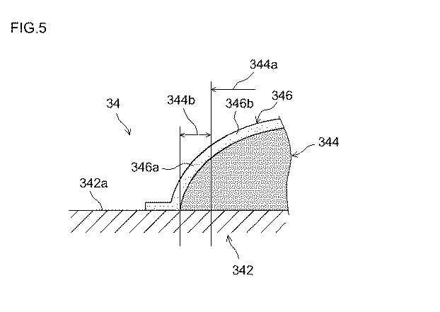
これらの図表に示されるように、気孔率比が0.25以上1未満の範囲にある例2,3では、十分に高い膜抵抗(具体的には10Ω/cm2)を有する多孔質無機層で負極活物質層の端部がすっかり覆われた構成でありながら、より膜抵抗の低い構成(例4)に比べて、電池の内部抵抗を同等以下に抑えることができた。すなわち、内部抵抗の上昇を抑えつつ、端部における微小短絡がよりよく防止された構成の電池を実現することができた。As shown in these charts, in Examples 2 and 3 in which the porosity ratio is in the range of 0.25 or more and less than 1, a porous inorganic layer having a sufficiently high membrane resistance (specifically, 10 Ω / cm 2 ). Thus, although the end portion of the negative electrode active material layer was completely covered, the internal resistance of the battery could be suppressed to the same level or lower as compared with the configuration having a lower membrane resistance (Example 4). That is, it was possible to realize a battery having a configuration in which a minute short circuit at the end portion was better prevented while suppressing an increase in internal resistance.
例1〜5に係る負極シートサンプルに関し、多孔質無機層の第1部分の形成に使用したスラリーの種類、該第1部分の気孔率Paおよび膜抵抗の値を表2に示す。また、第1部分の気孔率Paと膜抵抗との関係を図8に示す。 Table 2 shows the types of the slurry used for forming the first portion of the porous inorganic layer, the porosity Pa of the first portion, and the membrane resistance for the negative electrode sheet samples according to Examples 1 to 5. FIG. 8 shows the relationship between the porosity Pa of the first portion and the membrane resistance.
これらの図表に示されるように、気孔率Paを70体積%以下(より具体的には10〜65体積%)の範囲に抑えた例1〜3,5に係る多孔質絶縁層の第1部分は、いずれも十分に高い膜抵抗(具体的には10Ω/cm2)を示した。したがって、これらの例に係る負極シートによれば、例えば第1部分の気孔率Paが80体積%を超える例4に比べて、明らかに優れた短絡防止性を示すリチウムイオン電池が構築され得ることがわかる。As shown in these charts, the first portion of the porous insulating layer according to Examples 1 to 3 and 5 in which the porosity Pa is suppressed to a range of 70% by volume or less (more specifically, 10 to 65% by volume). All exhibited sufficiently high film resistance (specifically, 10 Ω / cm 2 ). Therefore, according to the negative electrode sheet according to these examples, it is possible to construct a lithium ion battery that clearly shows a short circuit prevention property as compared with Example 4 in which the porosity Pa of the first portion exceeds 80% by volume, for example. I understand.
[参考例]
なお、多孔質無機層の第1部分の目付を第2部分の目付よりも小さくすることの効果を確認するため、以下の実験を行った。本参考例では、上記スラリーX1を用いて多孔質無機層の全体(すなわち、第1部分および第2部分の両方)を形成した。スラリーX1の塗布量は、負極活物質層の平面部における目付量の目標値が0.65〜0.75μm/cm2となるように調整した。この調整は、上記裁断の前における負極活物質層の形成幅のうち一方の端からの距離が1/4,2/4および3/4となる位置について行った。また、上記裁断前における負極活物質層の長手方向に沿った両端部については、スラリーの目付量の目標値が上記平面部よりも多くなるようにグラビアコーターを調整し、あるいは上記平面部と同等の目付量でスラリーを塗布して多孔質無機層を形成した後に負極活物質層の長手方向に沿った両端から幅中央に向かって2mmまでの範囲につき上記無機層を紙やすりで削ることにより目付量を減らした。その他の点については例1〜5と同様にして、第1部分の目付Wa(ここでは、負極活物質層と活物質層非形成部との境界から1mm内側の部分につき測定した。)と、第2部分の目付Wb(ここでは、負極活物質層の幅のちょうど中央とした。)との質量比Wa/Wbが異なる9種の負極シートサンプルを作製した。これらの負極シートサンプルを用いた点以外は上記と同様にして、各負極シートサンプルに対応した計9種のリチウムイオン電池を得た。[Reference example]
In order to confirm the effect of making the basis weight of the first portion of the porous inorganic layer smaller than the basis weight of the second portion, the following experiment was performed. In this reference example, the entire porous inorganic layer (that is, both the first portion and the second portion) was formed using the slurry X1. The coating amount of the slurry X1 was adjusted such that the target value of the basis weight in the flat portion of the negative electrode active material layer was 0.65 to 0.75 μm / cm 2 . This adjustment was performed at positions where the distance from one end of the formation width of the negative electrode active material layer before the cutting was 1/4, 2/4, and 3/4. In addition, for both ends along the longitudinal direction of the negative electrode active material layer before cutting, the gravure coater is adjusted so that the target value of the basis weight of the slurry is larger than that of the plane portion, or equivalent to the plane portion. After forming the porous inorganic layer by applying the slurry in a weight per unit area of the negative electrode active material layer, the inorganic layer is scraped with a sandpaper in a range of 2 mm from both ends along the longitudinal direction toward the center of the width. Reduced the amount. The other points were the same as in Examples 1 to 5, and the basis weight Wa of the first part (here, measured for a
[容量維持性評価]
上記で作製した9種のリチウムイオン電池を、25℃において4.1Vから3.0Vまで5Aの定電流で放電させ、続いて合計放電時間が2時間となるまで定電圧で放電させて、かかるCC−CV放電における放電容量(初期容量)を測定した。次いで、各電池に対し、3.0Vから4.1Vまで5Aの定電流にて充電する操作と、4.1Vから3.0Vまで5Aの定電流にて放電させる操作とを交互に1000サイクル繰り返した。かかる充放電サイクル後の電池を4.1Vから3.0Vまで5Aの定電流で放電させ、続いて合計放電時間が2時間となるまで定電圧で放電させて、このときの放電容量(サイクル後容量)を測定した。そして、次式:[1−{(サイクル後容量)/(初期容量)}]×100;により、上記充放電サイクルによる容量減少率(%)を求めた。その結果を表3に示す。[Capacity maintenance evaluation]
The nine types of lithium ion batteries produced above were discharged at a constant current of 5 A from 4.1 V to 3.0 V at 25 ° C., and then discharged at a constant voltage until the total discharge time was 2 hours. The discharge capacity (initial capacity) in CC-CV discharge was measured. Next, the operation of charging each battery with a constant current of 5 A from 3.0 V to 4.1 V and the operation of discharging with a constant current of 5 A from 4.1 V to 3.0 V are alternately repeated 1000 cycles. It was. The battery after the charge / discharge cycle was discharged at a constant current of 5 A from 4.1 V to 3.0 V, and then discharged at a constant voltage until the total discharge time was 2 hours. Capacity). And the capacity reduction rate (%) by the said charging / discharging cycle was calculated | required by following Formula: [1-{(capacity after cycling) / (initial capacity)}] * 100; The results are shown in Table 3.
この表から明らかなように、Wa/Wbが凡そ0.5〜1.2の範囲にある負極シートサンプルを用いて構築されたリチウムイオン電池は、容量減少率が8%前後という高い容量維持性を示すものであった。これらの電池によると、Wa/Wbが0.5を下回るかあるいは1.2を上回る電池に比べて、より高い容量維持性が得られることが確認された。上記の実験結果と、Wa/Wbを1よりも小さくすることによる上述の効果(例えば、捲回電極体をより緊密に捲回し得ること、電解液その他の物質移動性を高め得ること)とから、Wa/Wbを0.5以上1未満の範囲とすれば、短絡防止性に優れるとともに、より高性能な(例えば、容量維持性、エネルギー密度、出力性能等のうち少なくとも一つが改善された)電池が実現され得ることがわかる。 As is apparent from this table, the lithium ion battery constructed using the negative electrode sheet sample having a Wa / Wb in the range of about 0.5 to 1.2 has a high capacity maintaining property with a capacity reduction rate of about 8%. Was shown. According to these batteries, it was confirmed that higher capacity retention was obtained as compared with batteries having Wa / Wb below 0.5 or above 1.2. From the above experimental results and the above-described effects by making Wa / Wb smaller than 1 (for example, the wound electrode body can be wound more closely, and the electrolyte and other mass mobility can be improved). When Wa / Wb is in the range of 0.5 or more and less than 1, it has excellent short circuit prevention and higher performance (for example, at least one of capacity maintenance, energy density, output performance, etc. has been improved). It can be seen that a battery can be realized.
以上、本発明の具体例を詳細に説明したが、これらは例示にすぎず、請求の範囲を限定するものではない。請求の範囲に記載の技術には、以上に例示した具体例を様々に変形、変更したものが含まれる。 As mentioned above, although the specific example of this invention was demonstrated in detail, these are only illustrations and do not limit a claim. The technology described in the claims includes various modifications and changes of the specific examples illustrated above.
本発明に係るリチウムイオン電池は、上記のとおり、微小短絡を高度に防止し得ることから信頼性が高く、且つ電池性能に優れたものとなり得る。例えば、5C以上、さらには10C以上のハイレート放電に対しても、内部抵抗を抑えつつ短絡防止性を高めることができる。かかる特長を活かして、本発明に係るリチウムイオン電池は、特に自動車等の車両に搭載されるモーター(電動機)用電源の構成要素として好適に利用され得る。したがって、本発明は、図9に模式的に示すように、ここに開示されるいずれかのリチウムイオン電池10(当該リチウムイオン電池10を複数個直列に接続して形成される組電池の形態であり得る。)を電源として備える車両(典型的には自動車、特にハイブリッド自動車、電気自動車、燃料電池自動車のような電動機を備える自動車)1を提供する。
As described above, the lithium ion battery according to the present invention can highly prevent a micro short circuit, and thus can be highly reliable and have excellent battery performance. For example, even for high rate discharge of 5C or higher, or even 10C or higher, short circuit prevention can be improved while suppressing internal resistance. Taking advantage of this feature, the lithium ion battery according to the present invention can be suitably used as a component of a power source for a motor (electric motor) mounted on a vehicle such as an automobile. Therefore, as schematically shown in FIG. 9, the present invention is in the form of any one of the
Claims (8)
ここで、前記負極活物質層は、前記負極集電体の長手方向に沿った少なくとも一方の縁を帯状に残して設けられており、
前記負極シートは、前記正極シートの長手方向に沿った一方の端部から前記帯状部分がはみ出し、かつ前記負極活物質層のうち前記帯状部分側の端部が前記正極活物質層からはみ出すようにして該正極シートと重ね合わされており、
前記負極活物質層の外表面には、該活物質層の平面部から前記帯状部分側の端部を回り込んで前記負極集電体表面に至る多孔質無機層が形成されており、
ここで、前記負極活物質層の帯状部分側端部における前記多孔質無機層の気孔率Pa[体積%]が、該活物質層の幅中央部における該無機層の気孔率Pb[体積%]よりも低い、リチウムイオン電池。A negative electrode sheet having a negative electrode active material layer on the surface of a long sheet-shaped negative electrode current collector, and a positive electrode sheet having a positive electrode active material layer on the surface of a long sheet-shaped positive electrode current collector, A lithium-ion battery including an electrode body that is rolled and wound through a separator,
Here, the negative electrode active material layer is provided leaving at least one edge in a strip shape along the longitudinal direction of the negative electrode current collector,
The negative electrode sheet, to protrude the ends of the strip-like portion side in the longitudinal direction while the strip portions from an end portion of the along the is protruded, and the negative active material layer of the positive electrode sheet from the positive electrode active material layer Is superimposed on the positive electrode sheet,
On the outer surface of the negative electrode active material layer, a porous inorganic layer is formed that wraps around the end of the band-shaped portion side from the flat portion of the active material layer and reaches the surface of the negative electrode current collector,
Here, the porosity Pa [volume%] of the porous inorganic layer at the end of the negative electrode active material layer on the side of the band-shaped portion is the porosity Pb [volume%] of the inorganic layer at the width center of the active material layer. Lower than lithium-ion battery.
前記単電池の各々は、正負の電極シートがセパレータを介して重ね合わされて捲回された電極体が容器に収容された構成を有し、
前記複数の単電池は、前記電極体の軸に対して横方向に配列され、且つ該配列方向に荷重が加えられた状態で拘束されており、
前記単電池のうち少なくとも一つは請求項1から4のいずれか一項に記載の電池である、組電池。An assembled battery comprising a plurality of cells arranged in a predetermined direction,
Each of the unit cells has a configuration in which an electrode body in which positive and negative electrode sheets are overlapped and wound via a separator is accommodated in a container,
The plurality of single cells are arranged in a direction transverse to the axis of the electrode body and are restrained in a state where a load is applied in the arrangement direction,
An assembled battery, wherein at least one of the single cells is a battery according to any one of claims 1 to 4.
負極集電体の表面に、該集電体の長手方向に沿った少なくとも一方の縁を帯状に残して負極活物質層を形成する工程;
前記負極活物質層が形成された負極集電体に、無機粒子とバインダとを含む無機層形成用スラリーを塗布して、前記負極活物質層の平面部から前記帯状部分側の端部を経て前記負極集電体表面に至る多孔質無機層を形成する工程、ここで、前記多孔質無機層は、前記負極活物質層の帯状部分側端部における該無機層の気孔率Pa[体積%]が、該活物質層の幅中央部における該無機層の気孔率Pb[体積%]よりも低くなるように形成される;
前記負極集電体の表面に前記負極活物質層および前記多孔質無機層を形成してなる負極シートを、前記セパレータを介して且つ前記正極シートの長手方向に沿った一方の端部から前記帯状部分がはみ出し、かつ前記負極活物質層のうち前記帯状部分側の端部が前記正極活物質層からはみ出すようにして該正極シートと重ね合わせ、それら重ね合わされた正極シート、負極シートおよびセパレータを捲回して電極体を構成する工程;および、
前記電極体を非水電解質とともに容器に収容してリチウムイオン電池を構築する工程;
を包含する、リチウムイオン電池製造方法。A method of manufacturing a lithium ion battery comprising an electrode body formed by winding a positive and negative electrode sheet having an active material layer formed on the surface of a long sheet-shaped current collector and a long sheet-shaped separator. :
Forming a negative electrode active material layer on the surface of the negative electrode current collector, leaving at least one edge in a strip shape along the longitudinal direction of the current collector;
An inorganic layer forming slurry containing inorganic particles and a binder is applied to the negative electrode current collector on which the negative electrode active material layer is formed, and the flat part of the negative electrode active material layer passes through the end on the band-shaped part side. A step of forming a porous inorganic layer reaching the surface of the negative electrode current collector, wherein the porous inorganic layer has a porosity Pa [volume%] of the inorganic layer at an end of the negative electrode active material layer on the side of the belt-like portion Is formed so as to be lower than the porosity Pb [volume%] of the inorganic layer in the center of the width of the active material layer;
The negative electrode sheet formed by forming the negative electrode active material layer and the porous inorganic layer on the surface of the negative electrode current collector is formed in the strip shape from one end portion along the longitudinal direction of the positive electrode sheet through the separator. portion is protruded, and superimposed with the positive electrode sheet end of said strip portion side in the Suyo protrudes from the positive electrode active material layer of the anode active material layer, they superposed positive electrode sheet, negative electrode sheet and separator Winding an electrode to form an electrode body; and
Storing the electrode body together with a non-aqueous electrolyte in a container to construct a lithium ion battery;
A method for producing a lithium ion battery.
Applications Claiming Priority (1)
| Application Number | Priority Date | Filing Date | Title |
|---|---|---|---|
| PCT/JP2009/057398 WO2010116533A1 (en) | 2009-04-10 | 2009-04-10 | Lithium ion battery and utilization thereof |
Publications (2)
| Publication Number | Publication Date |
|---|---|
| JPWO2010116533A1 JPWO2010116533A1 (en) | 2012-10-18 |
| JP5201426B2 true JP5201426B2 (en) | 2013-06-05 |
Family
ID=42935841
Family Applications (1)
| Application Number | Title | Priority Date | Filing Date |
|---|---|---|---|
| JP2010504357A Active JP5201426B2 (en) | 2009-04-10 | 2009-04-10 | Lithium ion battery and its use |
Country Status (5)
| Country | Link |
|---|---|
| US (1) | US8658305B2 (en) |
| JP (1) | JP5201426B2 (en) |
| KR (1) | KR101309925B1 (en) |
| CN (1) | CN102388498B (en) |
| WO (1) | WO2010116533A1 (en) |
Families Citing this family (23)
| Publication number | Priority date | Publication date | Assignee | Title |
|---|---|---|---|---|
| JP5071747B2 (en) * | 2011-01-13 | 2012-11-14 | 横河電機株式会社 | Secondary battery inspection device, secondary battery inspection method, secondary battery manufacturing method |
| CN102683735B (en) | 2011-03-16 | 2017-03-01 | 株式会社杰士汤浅国际 | Charge storage element |
| DE112011105872B4 (en) * | 2011-11-24 | 2021-09-09 | Toyota Jidosha Kabushiki Kaisha | Method for manufacturing a non-aqueous electrolyte secondary battery |
| JP5765574B2 (en) * | 2011-12-20 | 2015-08-19 | トヨタ自動車株式会社 | Secondary battery, method for producing the same, and method for producing negative electrode sheet used in the battery |
| US9531002B2 (en) * | 2012-03-28 | 2016-12-27 | Sharp Laboratories Of America, Inc. | Transition metal cyanometallate cathode battery with metal plating anode |
| JP6037713B2 (en) * | 2012-08-09 | 2016-12-07 | 三洋電機株式会社 | Nonaqueous electrolyte secondary battery |
| JP6114515B2 (en) | 2012-08-09 | 2017-04-12 | 三洋電機株式会社 | Non-aqueous electrolyte secondary battery and manufacturing method thereof |
| CN105074967B (en) * | 2013-03-15 | 2018-07-10 | 应用材料公司 | For manufacturing the multi-layer cell electrode design compared with thick electrode |
| JP6061145B2 (en) * | 2013-08-02 | 2017-01-18 | トヨタ自動車株式会社 | Secondary battery |
| JP6180895B2 (en) * | 2013-11-15 | 2017-08-16 | 国立大学法人信州大学 | Secondary battery electrode, method for manufacturing secondary battery electrode, and secondary battery |
| WO2016152055A1 (en) * | 2015-03-25 | 2016-09-29 | Sharp Kabushiki Kaisha | Transition metal cyanometallate cathode battery with metal plating anode |
| JP6176500B2 (en) * | 2015-04-21 | 2017-08-09 | トヨタ自動車株式会社 | Secondary battery, method for producing the same, and method for producing negative electrode sheet used in the battery |
| JP6674657B2 (en) * | 2016-03-04 | 2020-04-01 | 株式会社Gsユアサ | Storage element |
| WO2019017331A1 (en) * | 2017-07-18 | 2019-01-24 | 株式会社Gsユアサ | Electrode, power storage element and method for producing electrode |
| JP7013781B2 (en) * | 2017-10-12 | 2022-02-01 | 株式会社Gsユアサ | Electrodes, electrode manufacturing methods and power storage elements |
| JP7264289B2 (en) * | 2017-10-12 | 2023-04-25 | 株式会社Gsユアサ | ELECTRODE, METHOD FOR MANUFACTURING ELECTRODE, AND STORAGE ELEMENT |
| US12080843B2 (en) * | 2017-11-16 | 2024-09-03 | Apple Inc. | Battery cell with multiple separator layers that include adhesive and ceramic material |
| JP2019153434A (en) * | 2018-03-01 | 2019-09-12 | 株式会社東芝 | Laminate and secondary battery |
| WO2019244401A1 (en) * | 2018-06-19 | 2019-12-26 | 日立オートモティブシステムズ株式会社 | Lithium ion secondary battery and method for producing same |
| JP7394327B2 (en) * | 2019-03-27 | 2023-12-08 | パナソニックIpマネジメント株式会社 | secondary battery |
| CN112417725B (en) * | 2020-11-20 | 2024-07-12 | 湖南领湃达志科技股份有限公司 | Design method of porosity of negative plate |
| CN112820853A (en) * | 2020-12-30 | 2021-05-18 | 珠海冠宇电池股份有限公司 | Pole piece and battery |
| CN115458879B (en) * | 2022-09-28 | 2024-03-22 | 惠州锂威新能源科技有限公司 | Battery cell and battery cell manufacturing method |
Citations (4)
| Publication number | Priority date | Publication date | Assignee | Title |
|---|---|---|---|---|
| JP2006228544A (en) * | 2005-02-17 | 2006-08-31 | Matsushita Electric Ind Co Ltd | Lithium ion secondary battery |
| JP2008103110A (en) * | 2006-10-17 | 2008-05-01 | Nippon Leiz Co Ltd | Light guide plate and flat lighting device |
| JP2009038016A (en) * | 2007-07-09 | 2009-02-19 | Panasonic Corp | Electrode plate for nonaqueous electrolyte secondary battery and nonaqueous electrolyte secondary battery using the same |
| JP2010061819A (en) * | 2008-09-01 | 2010-03-18 | Panasonic Corp | Nonaqueous secondary battery |
Family Cites Families (6)
| Publication number | Priority date | Publication date | Assignee | Title |
|---|---|---|---|---|
| JPH11102730A (en) | 1997-09-29 | 1999-04-13 | Hitachi Ltd | Lithium secondary battery |
| JP4042413B2 (en) | 2002-01-11 | 2008-02-06 | 株式会社デンソー | battery |
| JP4454340B2 (en) | 2004-02-23 | 2010-04-21 | パナソニック株式会社 | Lithium ion secondary battery |
| CN100394632C (en) * | 2004-03-30 | 2008-06-11 | 松下电器产业株式会社 | Nonaqueous electrolyte secondary battery |
| JP2008103310A (en) * | 2006-09-19 | 2008-05-01 | Matsushita Electric Ind Co Ltd | Manufacturing method of electrode for secondary battery and secondary battery |
| WO2010067410A1 (en) | 2008-12-08 | 2010-06-17 | トヨタ自動車株式会社 | Lithium ion battery and method for manufacturing the same |
-
2009
- 2009-04-10 CN CN200980158641.7A patent/CN102388498B/en active Active
- 2009-04-10 WO PCT/JP2009/057398 patent/WO2010116533A1/en active Application Filing
- 2009-04-10 US US12/988,537 patent/US8658305B2/en active Active
- 2009-04-10 KR KR1020107028268A patent/KR101309925B1/en active IP Right Grant
- 2009-04-10 JP JP2010504357A patent/JP5201426B2/en active Active
Patent Citations (4)
| Publication number | Priority date | Publication date | Assignee | Title |
|---|---|---|---|---|
| JP2006228544A (en) * | 2005-02-17 | 2006-08-31 | Matsushita Electric Ind Co Ltd | Lithium ion secondary battery |
| JP2008103110A (en) * | 2006-10-17 | 2008-05-01 | Nippon Leiz Co Ltd | Light guide plate and flat lighting device |
| JP2009038016A (en) * | 2007-07-09 | 2009-02-19 | Panasonic Corp | Electrode plate for nonaqueous electrolyte secondary battery and nonaqueous electrolyte secondary battery using the same |
| JP2010061819A (en) * | 2008-09-01 | 2010-03-18 | Panasonic Corp | Nonaqueous secondary battery |
Also Published As
| Publication number | Publication date |
|---|---|
| KR20110018367A (en) | 2011-02-23 |
| JPWO2010116533A1 (en) | 2012-10-18 |
| WO2010116533A1 (en) | 2010-10-14 |
| CN102388498B (en) | 2014-04-23 |
| US20120021264A1 (en) | 2012-01-26 |
| US8658305B2 (en) | 2014-02-25 |
| KR101309925B1 (en) | 2013-09-17 |
| CN102388498A (en) | 2012-03-21 |
Similar Documents
| Publication | Publication Date | Title |
|---|---|---|
| JP5201426B2 (en) | Lithium ion battery and its use | |
| JP4766348B2 (en) | Lithium secondary battery and manufacturing method thereof | |
| JP5316905B2 (en) | Lithium secondary battery | |
| JP5365842B2 (en) | Lithium ion battery | |
| CN105453315B (en) | Secondary cell | |
| JP6587105B2 (en) | Secondary battery | |
| CN103872385B (en) | Rechargeable nonaqueous electrolytic battery | |
| JP4900695B2 (en) | Negative electrode for lithium secondary battery and lithium secondary battery | |
| US9997768B2 (en) | Lithium ion secondary battery and method for manufacturing lithium ion secondary battery | |
| JP6176500B2 (en) | Secondary battery, method for producing the same, and method for producing negative electrode sheet used in the battery | |
| JPWO2013094004A1 (en) | Lithium secondary battery | |
| JP2021086681A (en) | Nonaqueous electrolyte secondary battery | |
| JP2010102868A (en) | Lithium secondary battery | |
| JP5757329B2 (en) | Manufacturing method of secondary battery | |
| JP5999433B2 (en) | Nonaqueous electrolyte secondary battery and manufacturing method thereof | |
| JP5765574B2 (en) | Secondary battery, method for producing the same, and method for producing negative electrode sheet used in the battery | |
| JP6008188B2 (en) | Non-aqueous electrolyte secondary battery | |
| JP5168535B2 (en) | Lithium secondary battery and manufacturing method thereof | |
| EP2937920A1 (en) | Nonaqueous electrolyte secondary battery | |
| JP5692605B2 (en) | Non-aqueous electrolyte secondary battery | |
| WO2010067410A1 (en) | Lithium ion battery and method for manufacturing the same | |
| JP2014229554A (en) | Secondary battery and method for manufacturing the same | |
| JP6994152B2 (en) | Non-aqueous electrolyte secondary battery | |
| EP4030498B1 (en) | Graphite-based negative electrode active material | |
| JP7197537B2 (en) | lithium ion secondary battery |
Legal Events
| Date | Code | Title | Description |
|---|---|---|---|
| A131 | Notification of reasons for refusal |
Free format text: JAPANESE INTERMEDIATE CODE: A131 Effective date: 20120913 |
|
| A521 | Request for written amendment filed |
Free format text: JAPANESE INTERMEDIATE CODE: A523 Effective date: 20121024 |
|
| TRDD | Decision of grant or rejection written | ||
| A01 | Written decision to grant a patent or to grant a registration (utility model) |
Free format text: JAPANESE INTERMEDIATE CODE: A01 Effective date: 20130117 |
|
| A61 | First payment of annual fees (during grant procedure) |
Free format text: JAPANESE INTERMEDIATE CODE: A61 Effective date: 20130130 |
|
| R151 | Written notification of patent or utility model registration |
Ref document number: 5201426 Country of ref document: JP Free format text: JAPANESE INTERMEDIATE CODE: R151 |
|
| FPAY | Renewal fee payment (event date is renewal date of database) |
Free format text: PAYMENT UNTIL: 20160222 Year of fee payment: 3 |