JP5200654B2 - Manufacturing method of slinger with encoder and rolling bearing unit with encoder - Google Patents
Manufacturing method of slinger with encoder and rolling bearing unit with encoder Download PDFInfo
- Publication number
- JP5200654B2 JP5200654B2 JP2008124247A JP2008124247A JP5200654B2 JP 5200654 B2 JP5200654 B2 JP 5200654B2 JP 2008124247 A JP2008124247 A JP 2008124247A JP 2008124247 A JP2008124247 A JP 2008124247A JP 5200654 B2 JP5200654 B2 JP 5200654B2
- Authority
- JP
- Japan
- Prior art keywords
- slinger
- encoder
- adhesive
- fixed
- manufacturing
- Prior art date
- Legal status (The legal status is an assumption and is not a legal conclusion. Google has not performed a legal analysis and makes no representation as to the accuracy of the status listed.)
- Expired - Fee Related
Links
Images


Classifications
-
- F—MECHANICAL ENGINEERING; LIGHTING; HEATING; WEAPONS; BLASTING
- F16—ENGINEERING ELEMENTS AND UNITS; GENERAL MEASURES FOR PRODUCING AND MAINTAINING EFFECTIVE FUNCTIONING OF MACHINES OR INSTALLATIONS; THERMAL INSULATION IN GENERAL
- F16C—SHAFTS; FLEXIBLE SHAFTS; ELEMENTS OR CRANKSHAFT MECHANISMS; ROTARY BODIES OTHER THAN GEARING ELEMENTS; BEARINGS
- F16C33/00—Parts of bearings; Special methods for making bearings or parts thereof
- F16C33/72—Sealings
- F16C33/76—Sealings of ball or roller bearings
- F16C33/78—Sealings of ball or roller bearings with a diaphragm, disc, or ring, with or without resilient members
- F16C33/7869—Sealings of ball or roller bearings with a diaphragm, disc, or ring, with or without resilient members mounted with a cylindrical portion to the inner surface of the outer race and having a radial portion extending inward
- F16C33/7879—Sealings of ball or roller bearings with a diaphragm, disc, or ring, with or without resilient members mounted with a cylindrical portion to the inner surface of the outer race and having a radial portion extending inward with a further sealing ring
- F16C33/7883—Sealings of ball or roller bearings with a diaphragm, disc, or ring, with or without resilient members mounted with a cylindrical portion to the inner surface of the outer race and having a radial portion extending inward with a further sealing ring mounted to the inner race and of generally L-shape, the two sealing rings defining a sealing with box-shaped cross-section
-
- F—MECHANICAL ENGINEERING; LIGHTING; HEATING; WEAPONS; BLASTING
- F16—ENGINEERING ELEMENTS AND UNITS; GENERAL MEASURES FOR PRODUCING AND MAINTAINING EFFECTIVE FUNCTIONING OF MACHINES OR INSTALLATIONS; THERMAL INSULATION IN GENERAL
- F16C—SHAFTS; FLEXIBLE SHAFTS; ELEMENTS OR CRANKSHAFT MECHANISMS; ROTARY BODIES OTHER THAN GEARING ELEMENTS; BEARINGS
- F16C19/00—Bearings with rolling contact, for exclusively rotary movement
- F16C19/02—Bearings with rolling contact, for exclusively rotary movement with bearing balls essentially of the same size in one or more circular rows
- F16C19/14—Bearings with rolling contact, for exclusively rotary movement with bearing balls essentially of the same size in one or more circular rows for both radial and axial load
- F16C19/18—Bearings with rolling contact, for exclusively rotary movement with bearing balls essentially of the same size in one or more circular rows for both radial and axial load with two or more rows of balls
- F16C19/181—Bearings with rolling contact, for exclusively rotary movement with bearing balls essentially of the same size in one or more circular rows for both radial and axial load with two or more rows of balls with angular contact
- F16C19/183—Bearings with rolling contact, for exclusively rotary movement with bearing balls essentially of the same size in one or more circular rows for both radial and axial load with two or more rows of balls with angular contact with two rows at opposite angles
- F16C19/184—Bearings with rolling contact, for exclusively rotary movement with bearing balls essentially of the same size in one or more circular rows for both radial and axial load with two or more rows of balls with angular contact with two rows at opposite angles in O-arrangement
- F16C19/186—Bearings with rolling contact, for exclusively rotary movement with bearing balls essentially of the same size in one or more circular rows for both radial and axial load with two or more rows of balls with angular contact with two rows at opposite angles in O-arrangement with three raceways provided integrally on parts other than race rings, e.g. third generation hubs
-
- F—MECHANICAL ENGINEERING; LIGHTING; HEATING; WEAPONS; BLASTING
- F16—ENGINEERING ELEMENTS AND UNITS; GENERAL MEASURES FOR PRODUCING AND MAINTAINING EFFECTIVE FUNCTIONING OF MACHINES OR INSTALLATIONS; THERMAL INSULATION IN GENERAL
- F16C—SHAFTS; FLEXIBLE SHAFTS; ELEMENTS OR CRANKSHAFT MECHANISMS; ROTARY BODIES OTHER THAN GEARING ELEMENTS; BEARINGS
- F16C2326/00—Articles relating to transporting
- F16C2326/01—Parts of vehicles in general
- F16C2326/02—Wheel hubs or castors
Description
本発明は、例えば自動車等の車輪を懸加装置に対して回転自在に支持する為の車輪支持用転がり軸受ユニットを構成する、回転側軌道輪であるハブの端部に組み付けられる、回転検出機能を有する永久磁石製エンコーダと、シール装置を構成するスリンガ及びシールリップとが一体となった、エンコーダ付スリンガ、及び、この様なエンコーダ付スリンガを備えた転がり軸受ユニットの製造方法の改良に関する。 The present invention, for example, a rotation detection function that is assembled to the end of a hub that is a rotation-side bearing ring that constitutes a wheel bearing rolling bearing unit for rotatably supporting a wheel of an automobile or the like with respect to a suspension device. The present invention relates to a slinger with an encoder in which a slinger and a seal lip constituting a sealing device are integrated, and an improvement in a method for manufacturing a rolling bearing unit having such a slinger with an encoder .
アンチロックブレーキシステム(ABS)やトラクションコントロールシステム(TCS)を制御する為には、車輪の回転速度を求める必要がある。この為従来から、懸架装置に対して車輪を回転自在に支持する為の車輪支持用転がり軸受ユニット(ハブユニット)を構成する回転側軌道輪(ハブ)に、磁気特性を円周方向に関して交互に(一般的には等間隔に)変化させたエンコーダを固定する事が広く行われている。又、前記車輪支持用転がり軸受ユニットには、シールリングとスリンガとを組み合わせたシール装置(組み合わせシールリング)を組み込んで、複数個の転動体を設置した内部空間に、外部空間に存在する異物が進入したり、この内部空間内に存在するグリースが漏洩する事を防止する事が行われている。そして、前記エンコーダとスリンガとを結合して一体化する事も、例えば、特許文献1〜4に記載される等により、従来から広く知られている。 In order to control the anti-lock brake system (ABS) and the traction control system (TCS), it is necessary to determine the rotational speed of the wheels. For this reason, magnetic characteristics are alternately applied to the rotating raceway (hub) constituting the wheel bearing rolling bearing unit (hub unit) for rotatably supporting the wheel with respect to the suspension device in the circumferential direction. It is widely practiced to fix a changed encoder (generally at regular intervals). Further, the wheel bearing rolling bearing unit incorporates a seal device (combined seal ring) in which a seal ring and a slinger are combined, so that foreign matters existing in the external space are present in the internal space where a plurality of rolling elements are installed. It is possible to prevent the grease that enters or leaks in this internal space. And combining the encoder and the slinger and integrating them has been widely known, for example, as described in Patent Documents 1 to 4.
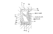
車輪支持用転がり軸受ユニットとエンコーダ付スリンガとの1例に就いて、図1、3により説明する。車輪支持用転がり軸受ユニット1は、固定側軌道輪である外輪2の内径側に、回転側軌道輪であるハブ3を、それぞれが転動体である複数個の玉4、4により、回転自在に支持している。尚、重量の嵩む自動車等の車輪支持用転がり軸受ユニットの場合には、転動体として、玉に代えて円すいころを使用する場合もある。このハブ3は、ハブ本体5と内輪6とを組み合わせて成る。前記車輪支持用転がり軸受ユニット1の使用時、前記外輪2は固定フランジ7により懸架装置に固定し、前記ハブ3の回転フランジ8に、ロータ等の制動用回転体と車輪とを固定する。このハブ3の外周面と前記外輪2の内周面との間に存在して前記各玉4、4を設置した内部空間9の両端開口のうち、前記回転フランジ8側の開口はシールリング10により、反対側開口は組み合わせシールリング11により、それぞれ塞いでいる。そして、前記内部空間9内への異物進入と、この内部空間9内に存在するグリースの漏洩とを防止している。
One example of the wheel bearing rolling bearing unit and the encoder-equipped slinger will be described with reference to FIGS. The wheel supporting rolling bearing unit 1 is configured such that a hub 3 that is a rotating raceway is provided on an inner diameter side of an
ABSやTCSを制御する為、前記ハブ3の回転速度を表す信号を得る為に従来から、前記組み合わせシールリング11にエンコーダ12(図3参照)を組み込んでいる。このうちの組み合わせシールリング11は、スリンガ13とシールリング14とを組み合わせて成る。このうちのスリンガ13は、ステンレス鋼板等の金属板を曲げ形成する事により、断面L字形で全体を円環状としたもので、内径側円筒部15と外向円輪部16とから成る。又、前記シールリング14は、芯金17とシール材18とを備える。このうちの芯金17は、ステンレス鋼板等の金属板を曲げ形成する事により、断面L字形で全体を円環状としたもので、外径側円筒部19と内向円輪部20とから成る。更に、前記シール材18は、ゴムの如きエラストマー製で、3本のシールリップ21a、21b、21cを有する。前記組み合わせシールリング11は、前記スリンガ13の内径側円筒部15を前記ハブ3(を構成する内輪6)の端部に外嵌固定し、前記芯金17の外径側円筒部19を前記外輪2の端部に内嵌固定した状態で、前記内部空間9の開口端部に組み付ける。又、この状態で、前記各シールリップ21a、21b、21cの先端縁を、前記スリンガ13の表面に、それぞれ全周に亙り摺接させて、前記内部空間9の開口端部を塞ぐ。
In order to control the ABS and TCS, an encoder 12 (see FIG. 3) has been incorporated in the combined
前記エンコーダ12は、前記スリンガ13の外向円輪部16のうちで前記内部空間9と反対側の側面に、全周に亙って、前記内径側円筒部15と同心に接合固定されている。前記エンコーダ12は永久磁石製で、軸方向に着磁されている。着磁方向は、円周方向に関して、交互に且つ等間隔で変化させている。従って、被検出面である、前記エンコーダ12の軸方向片側面には、S極とN極とが、円周方向に関して、交互に且つ等間隔で配置されている。この様なエンコーダ12を使用して、前記ハブ3の回転速度を測定する場合には、図3に示す様に、回転しない外輪2或いは懸架装置に支持固定されたセンサ22の検出部を、微小隙間を介して対向させる。前記ハブ3と共に前記エンコーダ12が回転すると、前記センサ22の出力信号が変化する。この出力信号が変化する周波数は、前記ハブ3の回転速度に比例するので、この出力信号を制御器に送れば、このハブ3に固定した、前記車輪の回転速度を求められる。
The
図3に示した、例えば特許文献1に記載された従来構造の第1例の場合、スリンガ13の側にはシールリップを設けておらず、前記内部空間9の開口端部のシール性は、前記シールリング14側に設けたシール材18のシールリップ21a、21b、21cのみで保持している。尚、一般的には、前記スリンガ13の外向円輪部16に接着剤を塗布した状態で、この外向円輪部16にエンコーダ素材を押し付け、プレス成形する事で、前記スリンガ13に前記エンコーダ12を接合する。又、前記エンコーダ素材として一般的には、フェライト等の磁性粉を含有したニトリルゴムを使用し、ロールでシート状に成形する事で、この磁性粉を機械的に配向している。
In the case of the first example of the conventional structure shown in FIG. 3 shown in FIG. 3, for example, no sealing lip is provided on the
これに対して、例えば特許文献3に記載された従来構造の第2例の場合、図1、2に記載した様に、シールリング14a側にシール材18aを設ける事に加えて、スリンガ13a側にもシール材18bを設ける事により、シールリップ21a〜21dの数を増やし、シール性の向上を図っている。但し、従来の場合には、図1、2に示した構造を実現する為に、前記スリンガ13aに対してシール材18bとエンコーダ12aとを、同種の接着剤により接着固定している。この為、これらシール材18bとエンコーダ12aとは、同種の接着剤により接着固定可能な材料である事が必要である。このうちのシール材18bは、十分な弾性を有するシールリップを設ける必要上、現状では、ゴム材料製でなければならない。この為、前記エンコーダ12aの材質に関しても、加硫接着が可能なゴム磁石とする必要がある(ゴム磁石以外の製造は、実際上困難乃至は不可能である)。
On the other hand, in the case of the second example of the conventional structure described in Patent Document 3, for example, as shown in FIGS. 1 and 2, in addition to providing the
この為従来は、図1、2に示した様な構造で、エンコーダ12aを、性能確保の面からゴム磁石に比べて有利な、プラスチック磁石製とする事はできなかった。即ち、固形状態であるプラスチック磁石は、未加硫ゴムの様な反応性がない。この為、プラスチック磁石を、半硬化状態の接着剤が塗布されたスリンガ13aと組み合わせた状態で、シール材18bを成形する為の金型内にセットし、このシール材18bをこのスリンガ13aに対して加硫接着する際の圧力と温度との履歴を与えても、このスリンガ13aとの接着強度を、実用レベルまで高める事はできなかった。この為従来は、図1、2に示した様に、スリンガ13aにエンコーダ12aとシール材18bとを接合した構造では、このエンコーダ12aを、強度、耐久性、着磁強度、ピッチ精度等の面から、ゴム磁石に比べて優れた性能を得易い、プラスチック磁石製とする事ができなかった。
For this reason, conventionally, the
本発明は、上述の様な事情に鑑みて、スリンガにエンコーダとシール材とを接合した構造で、このエンコーダを、ゴム磁石に比べて優れた性能を得易いプラスチック磁石製にできる、エンコーダ付スリンガ及びエンコーダ付転がり軸受ユニットの製造方法を実現すべく発明したものである。 In view of the circumstances as described above, the present invention has a structure in which an encoder and a sealing material are joined to a slinger, and the encoder can be made of a plastic magnet that easily obtains performance superior to that of a rubber magnet. And an invention for realizing a method of manufacturing a rolling bearing unit with an encoder .
本発明の製造方法の対象となるエンコーダ付スリンガは、エンコーダ付転がり軸受ユニットを構成する。又、このエンコーダ付転がり軸受ユニットは、固定側軌道輪及び回転側軌道輪と、複数個の転動体と、シール装置と、エンコーダとを備える。これら固定側軌道輪及び回転側軌道輪は、互いに同心に配置されている。又、前記各転動体は、これら両軌道輪の互いに対向する面に設けられた軌道面同士の間に、保持器に保持された状態で転動自在に配置されている。又、前記シール装置は、前記各転動体を設けた内部空間の端部開口を塞ぐ。更に、前記エンコーダは、前記回転側軌道輪の一部に固定された状態で前記シール装置を構成する磁性金属板製のスリンガの一部に全周に亙ってこのスリンガと同心に支持されたもので、プラスチック磁石製であって被検出面にS極とN極とを交互に配置している。 The slinger with encoder which is the object of the manufacturing method of the present invention constitutes a rolling bearing unit with encoder. The encoder-equipped rolling bearing unit includes a fixed-side raceway and a rotary-side raceway, a plurality of rolling elements, a seal device, and an encoder. The fixed side raceway and the rotation side raceway are arranged concentrically with each other. Each of the rolling elements is arranged so as to be able to roll while being held by a cage, between the raceway surfaces provided on the mutually opposing surfaces of these raceways. The sealing device closes an end opening of an internal space in which the rolling elements are provided. Furthermore, the encoder is supported concentrically with a part of the slinger made of a magnetic metal plate constituting the seal device in a state of being fixed to a part of the rotating side raceway, over the entire circumference. It is made of a plastic magnet, and S poles and N poles are alternately arranged on the detection surface.
特に、本発明のうち、請求項1に記載したエンコーダ付スリンガの製造方法は、前記スリンガのうちで前記エンコーダを設置すべき部分に接着剤を(例えばこのスリンガをこの接着剤が溶融した溶液中に浸漬する等により)塗布して、この接着剤を半硬化状態としてから、このスリンガを前記エンコーダを射出成形する為の金型のキャビティ内にセットする。そして、熱可塑性樹脂中に磁性粉末を混入したプラスチック磁石材料を、磁場を加えつつ溶融状態で前記キャビティ内に送り込んで、前記エンコーダと前記スリンガとを接合固定する。その後、このスリンガに別の接着剤を(例えばこのスリンガをこの別の接着剤が溶融した溶液中に浸漬する等により)塗布して、この別の接着剤を半硬化状態としてから、ゴム製で未加硫のシールリップと前記エンコーダを接合固定したスリンガとを組み合わせる。次いで、これらシールリップとスリンガとを、例えば金型内で加硫接着し、このスリンガの一部にこのシールリップの基部を接合固定する。
一方、請求項6に記載したエンコーダ付転がり軸受ユニットの製造方法は、上記スリンガと上記エンコーダと上記シールリップとを、上述した様なエンコーダ付スリンガの製造方法により接合固定する。
Particularly, in the present invention, the method of manufacturing the slinger with an encoder according to claim 1 is characterized in that an adhesive is applied to a portion of the slinger where the encoder is to be installed (for example, the slinger is in a solution in which the adhesive is melted). The slinger is set in a mold cavity for injection molding of the encoder. Then, a plastic magnet material in which magnetic powder is mixed in a thermoplastic resin is fed into the cavity in a molten state while applying a magnetic field, and the encoder and the slinger are bonded and fixed. Thereafter, another adhesive is applied to the slinger (for example, by immersing the slinger in a solution in which the other adhesive is melted), and the other adhesive is made into a semi-cured state. An unvulcanized seal lip is combined with a slinger to which the encoder is joined and fixed. Next, the seal lip and the slinger are bonded by vulcanization in a mold, for example, and the base of the seal lip is bonded and fixed to a part of the slinger.
On the other hand, in the manufacturing method of the rolling bearing unit with an encoder according to
この様な請求項1、6に記載した発明を実施する場合に好ましくは、請求項2に記載した発明の様に、前記エンコーダの射出成形をする為の金型のキャビティ内に、溶融状態の熱可塑性樹脂を送り込むゲートを、このキャビティの外周部に設けられたリングゲートとする。そして、射出成形後にこのリングゲートに対応する部分に形成されたバリを除去した後、前記エンコーダを着磁して、被検出面にS極とN極とを交互に配置する。尚、本来は、エンコーダ或いはプラスチック磁石となるのは、着磁後であるが、本明細書及び特許請求の範囲では、着磁前の状態でも、エンコーダ及びプラスチック磁石と称する。 In the case of carrying out the invention described in the first and sixth aspects, it is preferable that, as in the invention described in the second aspect, a molten state is formed in a cavity of a mold for injection molding of the encoder. The gate into which the thermoplastic resin is fed is a ring gate provided on the outer periphery of the cavity. Then, after removing the burrs formed on the portion corresponding to the ring gate after the injection molding, the encoder is magnetized, and S poles and N poles are alternately arranged on the detection surface. The encoder or the plastic magnet is originally after magnetization, but in the present specification and claims, the encoder and the plastic magnet are also referred to as encoder and plastic magnet.
又、請求項3に記載したエンコーダ付スリンガの製造方法の場合には、前記スリンガに接着剤を塗布してから、このスリンガとゴム製で未加硫のシールリップとを組み合わせる。その後、これらスリンガとシールリップとを加硫接着して、このスリンガの一部にこのシールリップの基部を接合固定する。次いで、熱可塑性樹脂中に磁性粉末を混入したプラスチック磁石材料を射出成形する事により別途造った前記エンコーダを前記スリンガに、別の接着剤により接着固定する。
この様な別の接着剤として好ましくは、請求項4に記載した発明の様に、常温での接着が可能な、室温硬化型接着剤を使用する。
In the method of manufacturing the slinger with encoder described in claim 3, after applying an adhesive to the slinger, the slinger is combined with a rubber-made unvulcanized seal lip. Thereafter, the slinger and the seal lip are vulcanized and bonded, and the base of the seal lip is joined and fixed to a part of the slinger. Next, the encoder made separately by injection molding a plastic magnet material in which magnetic powder is mixed in a thermoplastic resin is bonded and fixed to the slinger with another adhesive.
As such another adhesive, a room temperature curable adhesive capable of bonding at room temperature is preferably used as in the invention described in claim 4.
更に、上述した様な請求項3〜4に記載した発明を実施する場合に好ましくは、請求項5に記載した発明の様に、前記エンコーダの射出成形をする為の金型のキャビティ内に、溶融状態の熱可塑性樹脂を送り込むゲートを、このキャビティの内周部をゲートとしたディスクゲートと、このキャビティの外周部をゲートとしたリングゲートとのうちの一方とする。そして、射出成形後にこのゲートに対応する部分に形成されたバリを除去した後、スリンガに接着固定する以前に、前記エンコーダを着磁して、被検出面にS極とN極とを交互に配置する。
Further, when carrying out the invention described in claims 3 to 4 as described above, preferably, in the cavity of the mold for injection molding of the encoder, as in the invention described in
上述の様に構成する本発明のエンコーダ付スリンガ及びエンコーダ付転がり軸受ユニットの製造方法によれば、スリンガにエンコーダとシール材とを接合した構造で、このエンコーダを、ゴム磁石に比べて優れた性能を得易いプラスチック磁石製にできる。そして、前記スリンガに対する、前記エンコーダ及びシール材の接着強度に関する信頼性の確保を十分に図れる。 According to the manufacturing method of the slinger with encoder and the rolling bearing unit with encoder of the present invention configured as described above, the encoder has a structure in which the encoder and the seal material are joined to the slinger, and the encoder has superior performance compared to the rubber magnet. Can be made of plastic magnet. Further, it is possible to sufficiently ensure the reliability regarding the adhesive strength of the encoder and the sealing material to the slinger.
[実施の形態の第1例]
請求項1、2、6に対応する実施の形態の第1例に就いて、図1、2を参照しつつ説明する。尚、図1、2に示したエンコーダ付転がり軸受ユニットの構造に就いては、前述した通りであるから、重複する説明を省略若しくは簡略にし、以下、本発明のエンコーダ付スリンガの製造方法、及び、先に説明しなかった部分を中心に説明する。
プラスチック磁石であるエンコーダ12aと、シールリップ21c、21dを備えたゴム製のシール材18bとをスリンガ13aに接着固定して、シール材を備えたエンコーダ付スリンガを造る為に、先ず、スリンガ13aのうちで、前記エンコーダ12aを接着固定する接合面である、外向円輪部16の片側面(図1、2の右側面)に、エアーブラスト加工を施して、この片側面を、表面粗さがRaで1.3〜1.6である粗面とする。
[First example of embodiment]
A first example of the embodiment corresponding to
In order to produce a slinger with an encoder provided with a sealing material by adhering and fixing an
次いで、前記スリンガ13aを洗浄した後、フェノール樹脂を主成分とする接着剤の溶剤希釈液を、前記接合面にスプレーし、風乾後、一定温度で加熱して、この接着剤を半硬化状態とする。次いで、前記スリンガ13aを、前記エンコーダ12aを射出成形する為の金型のキャビティ内にセットした状態で、このキャビティ内に、合成樹脂中に磁性粉を混入した、プラスチック磁石材料を、加圧した状態で送り込み、プラスチック磁石である、前記エンコーダ12aを射出成形する。この際、アキシアル方向に磁場を加えて(磁場射出成形を行って)、このエンコーダ12aを構成する、前記プラスチック材料中の磁性粉を配向して(それぞれの長さ方向とアキシアル方向とを一致させて)、着磁後の磁気強度を高められる様にする。射出成形されたエンコーダ12aと前記スリンガ13aの外向円輪部16とを、成形時の熱によって接着固定する。接着強度をより高くする為には、更に加熱して、前記接着剤の硬化を進めても良い。
Next, after washing the
この様にして、前記スリンガ13aに前記エンコーダ12aを接合固定したならば、次に、このスリンガ13aを、(このエンコーダ12aごと)フェノール樹脂を主成分とするが、先の接着剤とは別種の接着剤の溶剤希釈液中に浸漬し、この希釈液から引き上げてから一定温度で加熱して、前記スリンガ13aの表面に付着した接着剤を半硬化状態とする。次いで、このスリンガ13aを、前記シール材18bを成形する為の金型のキャビティ内にセットし、圧縮成形又は射出成形により、このシール材18bを構成する為の未加硫ゴムを加硫して前記スリンガ13aに接着し、このシール材18bとする。
尚、このスリンガ13aに対し、前記エンコーダ12aを接着する為の接着剤と、前記シール材18bを接着する接着剤とは、これら両部材12a、18bの材質(プラスチック磁石材料であるかゴム材料であるか)によって適宜選定する。何れにしても、溶剤希釈と半硬化状態の実現とが可能で、樹脂成形或いは加硫によって接着が進行する性能を有するものを使用する。又、耐環境性を向上させる為に、接着剤を2層以上とする事もできる。
In this way, if the
The adhesive for adhering the
最後に、このスリンガ13aに接着固定された前記エンコーダ12aと図示しない着磁ヨークとを対向させて、このエンコーダ12aを軸方向に着磁し、このエンコーダ12aの被検出面である軸方向片側面に、S極とN極とを、円周方向に関して交互に、且つ、等間隔で配置する。尚、この着磁作業は、前記シール材18bを前記スリンガ13aに接着する前に行っても良い。その場合には、このシール材18bがない為、着磁ヨークとして、前記エンコーダ12aの被検出面を全周に亙り同時に着磁する(一発着磁を行う)円環状のものの他、このエンコーダ12aを回転させながら、順次着磁を行う回転着磁式のものも使用可能になる。
Finally, the
[実施の形態の第2例]
請求項1、3〜6に対応する実施の形態の第2例に就いて、図4、5を参照しつつ説明する。本例の場合には、スリンガ13bを構成する外向円輪部16の外周縁部に、図4に示す様に内径側円筒部15と軸方向反対側に折れ曲がった、或いは図5に示す様に折り返された、外径側折れ曲がり部23、23aを形成している。そして、この外径側折れ曲がり部23、23aを、前記スリンガ13bとエンコーダ12bとを接着固定する際に、これらスリンガ13bとエンコーダ12bとの中心を一致させる為の案内としての役目を持たせる様にしている。
[Second Example of Embodiment]
A second example of the embodiment corresponding to claims 1 and 3 to 6 will be described with reference to FIGS. In the case of this example, the outer peripheral edge portion of the
この様な構造は、次の様な工程で造る。
(1) 前記スリンガ13bを洗浄した後、フェノール樹脂を主成分とする接着剤の溶剤希釈液中にこのスリンガ13bを浸漬し、この希釈液から引き上げた後に一定温度で加熱して、前記接着剤を半硬化状態とする。
尚、前記スリンガ13bへの接着剤の塗布は、スプレーにより必要個所(シール材18cを接合する部分)のみに行っても良いが、コスト的には、希釈液中への浸漬による全面塗布が好ましい。
(2) 前記スリンガ13bを、シール材18cを成形する為の金型のキャビティ内にセットし、圧縮成形又は射出成形により、未加硫ゴムを前記スリンガ13bに加硫接着して、前記シール材18cを成形する。
(3) このシール材18cを成形するのとは別に、プラスチック磁石材料を、別の金型により磁場射出成形する。この別の金型は、内周部をゲートとしたディスクゲート、又は、外周部をゲートとしたリングゲートの少なくともどちらか一方のゲートを有する。射出成形後、得られたエンコーダ12bの内周縁又は外周縁に、このゲートに対応して生じたバリを除去する。
(4) 得られたエンコーダ12bを図示しない着磁ヨークの着磁面に突き合わせて軸方向に着磁し、このエンコーダ12bの被検出面に、S極とN極とを、円周方向に関して交互に、且つ、等間隔で配置する。
(5) 前記スリンガ13bの外向円輪部16の軸方向片側面(図4、5の右側面)に接着剤を塗布した後、前記外径側折れ曲がり部23、23aを案内として、前記エンコーダ12bと前記スリンガ13bとを同心に重ね合わせてから、これら両部材12b、13bを、接着剤により接着固定する。この接着剤の硬化方法は、使用する接着剤によって適宜選定されるが、接着剤として、常温で硬化が進むものが、芯ずれを防止して良質のエンコーダ付スリンガを得る面からは好ましい。
Such a structure is manufactured by the following process.
(1) After washing the
The adhesive may be applied to the
(2) The
(3) Separately from molding the sealing
(4) The obtained
(5) After applying an adhesive to one axial side surface (the right side surface in FIGS. 4 and 5) of the
[実施の形態の第3例]
請求項1、3〜6に対応する実施の形態の第3例に就いて、図6を参照しつつ説明する。本例の場合には、スリンガ13aの外向円輪部16の外周縁部に、単一のシールリップ21dを備えたシール材18dを接合固定している。
この様な構造は、次の様な工程で造る。
(1) 前記スリンガ13aを洗浄後、フェノール樹脂を主成分とする接着剤の溶剤希釈液中に浸漬し、この希釈液から引き上げた後に一定温度で加熱して、接着剤を半硬化状態とする。
(2) 前記スリンガ13aを、前記シール材18dを成形する為の金型のキャビティ内にセットし、圧縮成形又は射出成形により、未加硫ゴムを前記スリンガ13aに加硫接着して、前記シール材18dを成形する。
(3) このシール材18dを成形するのとは別に、プラスチック磁石材料を、別の金型により磁場射出成形する。この別の金型は、内周部をゲートとしたディスクゲート、又は、外周部をゲートとしたリングゲートを有する。射出成形後、得られたエンコーダ12bの内周縁又は外周縁に、ゲートに対応して生じたバリを除去する。
(4) 得られたエンコーダ12bを図示しない着磁ヨークの着磁面に突き合わせて軸方向に着磁し、このエンコーダ12bの被検出面に、S極とN極とを、円周方向に関して交互に、且つ、等間隔で配置する。
(5) 前記スリンガ13aの外向円輪部16の軸方向片側面(図6右側面)に接着剤を塗布した後、前記エンコーダ12bと前記スリンガ13aとを、治具を使って中心を一致させながら同心に重ね合わせ、これら両部材12b、13aを、接着剤により接着固定する。この接着剤の硬化方法は、使用する接着剤によって適宜選定されるが、接着剤として、常温で硬化が進むものが、芯ずれを防止して良質のエンコーダ付スリンガを得る面からは好ましい。
[Third example of embodiment]
A third example of the embodiment corresponding to claims 1 and 3 to 6 will be described with reference to FIG. In the case of this example, a sealing
Such a structure is manufactured by the following process.
(1) After washing the
(2) The
(3) Separately from molding the sealing
(4) The obtained
(5) After applying adhesive on one axial side surface (right side surface in FIG. 6) of the
以上に述べた実施の形態の各例を含め、本発明のエンコーダ付スリンガ及びエンコーダ付転がり軸受ユニットの製造方法を実施する場合に、エンコーダを構成するプラスチック磁石の材料は、特に限定しない。但し、このプラスチック磁石の成形、接着、別体成形後のスリンガへの接着を考慮すると、磁性粉を70〜92重量%程度含有し、熱可塑性樹脂をバインダとした磁石コンパウンドを使用する事が好ましい。このうちの磁性粉としては、ストロンチウムフェライトやバリウムフェライト等のフェライト、ネオジウム−鉄−ボロン、サマリウム−コバルト、サマリウム−鉄−窒素等の希土類磁性粉を用いる事ができ、更にフェライトの磁気特性を向上させる為に、ランタン等の希土類元素を混入させたものを使用する事もできる。 Including the examples of the embodiments described above, when the manufacturing method of the slinger with encoder and the rolling bearing unit with encoder of the present invention is carried out, the material of the plastic magnet constituting the encoder is not particularly limited. However, in consideration of molding and adhesion of this plastic magnet and adhesion to slinger after separate molding, it is preferable to use a magnet compound containing about 70 to 92% by weight of magnetic powder and using a thermoplastic resin as a binder. . As magnetic powder, ferrite such as strontium ferrite and barium ferrite, rare earth magnetic powder such as neodymium-iron-boron, samarium-cobalt, samarium-iron-nitrogen can be used, and the magnetic properties of ferrite are further improved. In order to achieve this, a material mixed with a rare earth element such as lanthanum can be used.
尚、磁性粉の含有量が70重量%未満の場合は、磁気特性が劣ると共に、細かいピッチで円周方向に多極磁化させる事が困難になり、好ましくない。これに対して、磁性粉の含有量が92重量%を越える場合は、バインダ量が少なくなり過ぎて、磁石全体の強度が低くなると同時に、成形が困難になり、実用性が低下する。 In addition, when the content of the magnetic powder is less than 70% by weight, the magnetic properties are inferior, and it becomes difficult to perform multipolar magnetization in the circumferential direction at a fine pitch, which is not preferable. On the other hand, when the content of the magnetic powder exceeds 92% by weight, the amount of the binder becomes too small, the strength of the whole magnet is lowered, and at the same time, molding becomes difficult and practicality is lowered.
又、前記エンコーダを構成するプラスチック磁石のバインダとして使用する熱可塑性樹脂は、射出成形可能なものが好適であり、具体的には、ポリアミド6、ポリアミド66、ポリアミド12、ポリアミド612、ポリアミド610、ポリアミド11、ポリフェニレンサルファイド(PPS)、変性ポリアミド6T、ポリアミド9T、分子構造中にソフトセグメントを有する変性ポリアミド12、分子構造中にソフトセグメントを有するポリアミド612、分子構造中にソフトセグメントを有する変性ポリエステル樹脂、分子構造中にソフトセグメントを有する変性ポリスチレン等を用いる事ができる。尚、磁石部に、融雪剤として使用される塩化カルシウムが水と一緒に付着する可能性があるので、吸水性が少ないポリアミド12、ポリアミド612、ポリアミド610、ポリアミド11、ポリフェニレンサルファイド(PPS)、変性ポリアミド6T、ポリアミド9T、変性ポリアミド12、変性ポリエステル、変性ポリスチレンを樹脂バインダとする方が、より好ましい。
The thermoplastic resin used as the binder of the plastic magnet constituting the encoder is preferably an injection-moldable one. Specifically,
更に、転がり軸受ユニットの使用環境で想定される急激な温度変化(熱衝撃)による亀裂発生を防止するバインダとしては、添加する事で、曲げ撓み性、耐亀裂性が向上する、変性ポリアミド12、変性ポリアミド612、変性ポリエステル、変性ポリスチレン、或いは変性ポリアミド12とポリアミド12との混合物、変性ポリアミド12とポリアミド612との混合物、変性ポリアミド612とポリアミド612との混合物、変性ポリエステル樹脂とポリエステル樹脂との混合物、変性ポリスチレンとポリスチレンとの混合物としたものが最も好適である。又、耐熱衝撃性バインダとしては、上述したソフトセグメントを有しない樹脂と、変性ポリアミド12等と同様の役割をする、その他の耐衝撃性向上材との組み合わせであっても良い。
Furthermore, as a binder for preventing the occurrence of cracks due to a sudden temperature change (thermal shock) assumed in the usage environment of the rolling bearing unit, the modified
その他の耐衝撃性向上材としては、各種の加硫ゴム超微粒子を用いる事ができる。具体的には、スチレンブタジエンゴム、アクリルゴム、アクリロニトリルブタジエンゴム、カルボキシル変性アクリロニトリルブタジエンゴム、シリコンゴム、クロロプレンゴム、水素添加ニトリルゴム、カルボキシル変性水素添加ニトリルゴム、カルボキシル変性スチレンブタジエンゴムの中から選ばれる少なくとも一種類で、平均粒子径で30〜300nmの範囲に入る微細な微粒子が、好ましく使用できる。平均粒子径が30nm未満の場合は、製造上コストが嵩むだけでなく、微細過ぎて劣化し易く、好ましくない。これに対して、平均粒子径が300nmを越える場合は、分散性が抵下する共に、耐衝撃性の改善を均一に行う事が難しく、やはり好ましくない。 Various other vulcanized rubber ultrafine particles can be used as other impact resistance improving materials. Specifically, it is selected from styrene butadiene rubber, acrylic rubber, acrylonitrile butadiene rubber, carboxyl modified acrylonitrile butadiene rubber, silicon rubber, chloroprene rubber, hydrogenated nitrile rubber, carboxyl modified hydrogenated nitrile rubber, and carboxyl modified styrene butadiene rubber. At least one kind of fine fine particles falling in the range of 30 to 300 nm in average particle diameter can be preferably used. When the average particle diameter is less than 30 nm, not only the production cost increases, but it is too fine to easily deteriorate, which is not preferable. On the other hand, when the average particle diameter exceeds 300 nm, the dispersibility deteriorates and it is difficult to uniformly improve the impact resistance.
上述した加硫ゴム超微粒子の中で、ペレット製造及び実際の磁石部成形時の劣化を考慮すると、アクリロニトリルブタジエンゴム(ニトリルゴム)、カルボキシル変性アクリロニトリルブタジエンゴム、アクリルゴム、シリコンゴム、水素添加ニトリルゴム、カルボキシル変性水素添加ニトリルゴムが好適である。特にその中でも、分子構造中に、カルボキシル基やエステル基等の有機官能基を有するものが、樹脂バインダとの相互作用が比較的強い為に、更に好適で、具体的にはカルボキシル変性アクリロニトリルブタジエンゴム、アクリルゴム、カルボキシル変性水素添加ニトリルゴムが、好ましく使用できる。これらの加硫ゴム超微粒子は、熱や酸素での劣化を防止して、4,4’−(α,α−ジメチルベンジル)ジフェニルアミン等のジフェニルアミン系老化防止剤、2−メルカプトベンズイミダゾール等の二次老化防止剤等を含有させたものとしても良い。 Among the vulcanized rubber ultrafine particles mentioned above, considering the deterioration during pellet production and actual magnet part molding, acrylonitrile butadiene rubber (nitrile rubber), carboxyl-modified acrylonitrile butadiene rubber, acrylic rubber, silicone rubber, hydrogenated nitrile rubber Carboxyl-modified hydrogenated nitrile rubber is preferred. Among them, those having an organic functional group such as a carboxyl group or an ester group in the molecular structure are more preferable because of their relatively strong interaction with the resin binder, specifically, carboxyl-modified acrylonitrile butadiene rubber. Acrylic rubber and carboxyl-modified hydrogenated nitrile rubber can be preferably used. These vulcanized rubber ultrafine particles prevent deterioration due to heat or oxygen, and diphenylamine-based anti-aging agents such as 4,4 ′-(α, α-dimethylbenzyl) diphenylamine, and 2-mercaptobenzimidazole and the like. It is good also as what contained the sub-aging inhibitor.
更に、耐衝撃性向上材として混入させるものとしては、その他に、エチレンプロピレン非共役ジエンゴム(EPDM)、無水マレイン酸変性エチレンプロピレン非共役ジエンゴム(EPDM)、エチレン/アクリレート共重合体、アイオノマー、グリシジルメタクリレートを分子構造中に3〜20%含有するエチレン系共重合体等も、使用可能である。これらの化合物はペレット状であり、磁性体粉、熱可塑性樹脂等と混合して押出機でペレット化する際に、流動化し、バインダ中にミクロ分散される。 In addition, other materials to be incorporated as impact resistance improvers include ethylene propylene non-conjugated diene rubber (EPDM), maleic anhydride-modified ethylene propylene non-conjugated diene rubber (EPDM), ethylene / acrylate copolymer, ionomer, glycidyl methacrylate. An ethylene copolymer containing 3 to 20% in the molecular structure can also be used. These compounds are in the form of pellets, which are fluidized and microdispersed in the binder when mixed with magnetic powder, thermoplastic resin, etc. and pelletized with an extruder.
又、前記変性樹脂或いは加硫ゴム超微粒子等から成る耐衝撃性向上材の添加量は、熱可塑性樹脂と併せたバインダ全量中で、5〜60重量%、より好ましくは10〜40重量%とする。添加量が5重量%未満の場合は、少な過ぎて耐衝撃性の改善効果が少なく、好ましくない。これに対して、添加量が60重量%を越える場合は、耐衝撃性は向上するものの、樹脂成分が少なくなる事で引張強度等が低下する為、実用性が低くなる。 Further, the impact resistance improving material comprising the modified resin or vulcanized rubber ultrafine particles is added in an amount of 5 to 60% by weight, more preferably 10 to 40% by weight in the total amount of the binder combined with the thermoplastic resin. To do. When the amount added is less than 5% by weight, the amount is too small, and the effect of improving the impact resistance is small. On the other hand, when the addition amount exceeds 60% by weight, although the impact resistance is improved, the tensile strength and the like are reduced due to the decrease in the resin component, so the practicality is lowered.
更に、バインダである熱可塑性樹脂及び耐衝撃性向上材(変性樹脂或いは加硫ゴム超微粒子等)の熱による劣化を防止する為に、元々材料に添加されているものの他に、酸化防止効果の高いアミン系酸化防止剤を添加する事は、熱による劣化が防止できる為、好ましい。この場合に使用するアミン系酸化防止剤としては、4,4’−(α,α−ジメチルベンジル)ジフェニルアミン、4,4’−ジオクチルジフェニルアミン等のジフェニルアミン系化合物、N,N’−ジフェニル−p−フェニレンジアミン、N−イソプロピル−N’−フェニル−p−フェニレンジアミン、N,N’−ジ−2−ナフチル−p−フェニレンジアミン、N,N’−ビス(1−メチルヘプチル)−p−フェニレンジアミン、N,N’−ビス(1,4−ジメチルペンチル)−p−フェニレンジアミン、N−(1,3−ジメチルブチル)−N’−フェニル−p−フェニレンジアミン等のp−フェニレンジアミン系化合物が好適である。 Furthermore, in order to prevent deterioration of the binder thermoplastic resin and impact resistance improving material (modified resin or vulcanized rubber ultrafine particles, etc.) due to heat, in addition to those originally added to the material, it has an antioxidant effect. It is preferable to add a high amine-based antioxidant because deterioration due to heat can be prevented. As the amine antioxidant used in this case, diphenylamine compounds such as 4,4 ′-(α, α-dimethylbenzyl) diphenylamine and 4,4′-dioctyldiphenylamine, N, N′-diphenyl-p- Phenylenediamine, N-isopropyl-N′-phenyl-p-phenylenediamine, N, N′-di-2-naphthyl-p-phenylenediamine, N, N′-bis (1-methylheptyl) -p-phenylenediamine P-phenylenediamine compounds such as N, N′-bis (1,4-dimethylpentyl) -p-phenylenediamine and N- (1,3-dimethylbutyl) -N′-phenyl-p-phenylenediamine. Is preferred.
前記アミン系酸化防止剤の添加量は、熱可塑性樹脂と耐衝撃性向上材から成るバインダ重量と酸化防止剤重量を加えた合算重量に対して、0.5〜2.0重量%程度が好ましい。アミン系酸化防止剤の添加量が0.5重量%未満の場合は、酸化防止の改善効果が十分でなく、好ましくない。これに対して、酸化防止剤の添加量が2.0重量%を越える場合は、酸化防止の効果がそれ以上向上しなくなると共に、その分、磁性体粉やバインダの量が減る為、磁気特性や機械的強度の低下に結び付いて好ましくない。しかも、場合によっては、成形品の表面にブルーム等を引き起こし、これがシール装置との接着に悪影響を及ぼす可能性がある為、好ましくない。バインダとして通常のソフトセグメントを有しない熱可塑性樹脂のみでは、23℃での曲げ撓み量(t=3.0mm、ASTM D790;スパン間距離50mm)が1〜2mmの範囲であるのに対し、耐衝撃性向上材を含有させる事で、同条件での撓み量が2〜15mm程度になる。この様に優れた撓み性を持たせる事により、耐亀裂性を向上させて、高温⇔低温が繰り返される等、厳しい使用環境下でも、エンコーダに亀裂等の破損が発生しにくくできる。 The addition amount of the amine-based antioxidant is preferably about 0.5 to 2.0% by weight with respect to the combined weight of the binder weight and the antioxidant weight made of the thermoplastic resin and the impact resistance improving material. . When the added amount of the amine antioxidant is less than 0.5% by weight, the effect of improving the antioxidant is not sufficient, which is not preferable. On the other hand, when the addition amount of the antioxidant exceeds 2.0% by weight, the antioxidant effect is not improved any more, and the amount of magnetic powder and binder is reduced correspondingly, so that the magnetic properties are reduced. It is not preferable because it leads to a decrease in mechanical strength. In addition, in some cases, bloom or the like is caused on the surface of the molded product, which may adversely affect the adhesion with the sealing device, which is not preferable. With only a thermoplastic resin having no ordinary soft segment as a binder, the bending deflection at 23 ° C. (t = 3.0 mm, ASTM D790; span distance 50 mm) is in the range of 1 to 2 mm. By including an impact improvement material, the amount of deflection under the same conditions becomes about 2 to 15 mm. By having such excellent flexibility, crack resistance can be improved, and it is difficult for the encoder to be cracked or damaged even under severe use environments such as repeated high and low temperatures.
又、磁性粉としては、コスト、耐酸化性を考慮すると、フェライト系が最も好適である。磁気特性を優先して希土類系を使用した場合、フェライト系に比べて、耐酸化性が低くなる。従って、長期間に亙って安定した磁気特性を維持させる為に、外部に露出したエンコーダの表面に、表面処理層を設けても良い。この場合に使用する表面処理層として具体的には、電気メッキ或いは無電解ニッケルメッキ、エポキシ樹脂塗膜、シリコン樹脂塗膜、フッ素樹脂塗膜等を使用できる。 As the magnetic powder, ferrite is most preferable in consideration of cost and oxidation resistance. When rare earths are used with priority on magnetic properties, the oxidation resistance is lower than that of ferrites. Therefore, in order to maintain stable magnetic characteristics over a long period of time, a surface treatment layer may be provided on the surface of the encoder exposed to the outside. Specifically, as the surface treatment layer used in this case, electroplating or electroless nickel plating, epoxy resin coating, silicon resin coating, fluorine resin coating, or the like can be used.
何れにしても、磁性粉は、目標とする磁気特性、使用環境、コストで使い分ける。磁気特性がBHmaxで1.4〜2.2MGOe程度であれば、ストロンチウムフェライト等のフェライト系磁性粉で十分に対応できる。又、更に回転速度検出の精度を向上させる為に、BHmaxを2.2〜5MGOe程度とする場合は、ストロンチウムフェライト等のフェライト系磁性粉と希土類系磁性粉とのハイブリッド化、或いは希土類系磁性粉のみでの配合とする事が好ましい。 In any case, the magnetic powder is properly used depending on the target magnetic characteristics, usage environment, and cost. If the magnetic properties are about 1.4 to 2.2 MGOe in terms of BHmax, a ferrite-based magnetic powder such as strontium ferrite can be sufficiently used. Further, in order to further improve the accuracy of rotational speed detection, when BHmax is set to about 2.2 to 5 MGOe, a hybrid of ferrite magnetic powder such as strontium ferrite and rare earth magnetic powder, or rare earth magnetic powder It is preferable to use only a blend.
又、組み合わせシールリングを構成する、スリンガ、或いはシールリングを構成する芯金の材質としては、フェライト系ステンレス(SUS430等)、マルテンサイト系ステンレス(SUS410等)等の磁性ステンレスを使用できる。更に、より高い耐食性が必要な場合は、Mo等を添加して耐食性を向上させた、SUS434、SUS444等の高耐食性磁性フェライト系ステンレス等の磁性金属材料が好適である。又、プラスチック磁石と接着剤との間では、ゴム材料の場合に生じる、加硫接着の様な活発な反応が起こらない事から、接着強度や塩水等の薬品に対する接着耐久性が低くなる傾向がある。従って、前記プラスチック磁石と接着剤との間の接着の信頼性を高める為に、少なくともこのプラスチック磁石の接合面に、接着剤との接合力を向上させる為の微細な凹凸を設ける事が好ましい。この場合に、この微細な凹凸を設ける方法としては、ショットブラスト処理やプレス成形時の金型表面の凹凸の転写による方法等の機械的なものの他、一度表面処理した表面を酸等によって化学エッチングしても良い。何れにしても、前記プラスチック磁石の接合面に微細な凹凸を設けると、アンカー効果に基づいて、このプラスチック磁石と前記スリンガとの結合力が向上する。尚、スリンガに未加硫ゴムを加硫接着する事でシールリップ部を形成してから、別体で成形したプラスチック磁石を接着固定する場合には、このプラスチック磁石のうちで前記スリンガとの接着面となる部分の表面に、ゴム製のシール材を加硫接着する為のフェノール樹脂等の接着剤硬化層が残存していても構わない。但し、この場合には、この残存している接着剤硬化層と、プラスチック磁石との、両方に接着力を有する接着剤を選定使用する。 Further, as a material of the slinger or the metal core constituting the seal ring constituting the combined seal ring, magnetic stainless steel such as ferritic stainless steel (SUS430, etc.), martensitic stainless steel (SUS410, etc.) can be used. Furthermore, when higher corrosion resistance is required, a magnetic metal material such as SUS434, SUS444, or other high corrosion resistance magnetic ferritic stainless steel that has been improved by adding Mo or the like is suitable. In addition, since there is no active reaction such as vulcanization bonding that occurs in the case of rubber materials between the plastic magnet and the adhesive, there is a tendency that the bonding strength and the bonding durability against chemicals such as salt water are lowered. is there. Therefore, in order to increase the reliability of the adhesion between the plastic magnet and the adhesive, it is preferable to provide at least the uneven surface for improving the bonding force with the adhesive on the bonding surface of the plastic magnet. In this case, as a method of providing this fine unevenness, mechanical etching such as shot blasting or transfer of unevenness on the mold surface during press molding, as well as chemical etching of the surface once surface-treated with acid etc. You may do it. In any case, when a fine unevenness is provided on the joint surface of the plastic magnet, the bonding force between the plastic magnet and the slinger is improved based on the anchor effect. In addition, after forming a seal lip part by vulcanizing and bonding unvulcanized rubber to a slinger, when bonding and fixing a plastic magnet molded separately, the adhesion to the slinger among the plastic magnets A cured adhesive layer such as a phenolic resin for vulcanizing and bonding a rubber seal material may remain on the surface of the surface portion. However, in this case, an adhesive having an adhesive force is selected and used for both the remaining adhesive cured layer and the plastic magnet.
又、スリンガ及び芯金にそれぞれの基端部を接合するシール材は、これらスリンガ又は芯金に加硫接着される為、材質としては、ニトリルゴムをベースとした配合が適切である。使用環境によって、更に耐熱性が必要な場合は、水素添加ニトリルゴム、アクリルゴム、フッ素ゴム、シリコンゴム等に材料を変更する事が好ましい。ゴムの加硫接着温度は、ゴムの種類、配合と、組み合わせるエンコーダを構成するプラスチック磁石材料の融点等とを考慮に入れて、適宜決定する。この点を考慮すれば、使用するプラスチック磁石材料は、200℃程度の高融点を有する材料を選定する事が好ましい。具体的には、このプラスチック磁石のバインダの主成分となる熱可塑性樹脂は、ポリアミド612、ポリアミド610、変性ポリアミド612、ポリフェニレンサルファイド(PPS)、変性ポリアミド6T、ポリアミド9T等が、採用可能である。尚、シールリップを構成するシール材の成形は、未加硫ゴムを用いて、射出成形或いは圧縮成形により行う。 Moreover, since the sealing material which joins each base end part to a slinger and a metal core is vulcanized-bonded to these slinger or a metal core, the mixing | blending based on a nitrile rubber is suitable as a material. If further heat resistance is required depending on the use environment, it is preferable to change the material to hydrogenated nitrile rubber, acrylic rubber, fluorine rubber, silicon rubber or the like. The vulcanization bonding temperature of rubber is appropriately determined in consideration of the type and composition of rubber and the melting point of the plastic magnet material constituting the encoder to be combined. Considering this point, it is preferable to select a material having a high melting point of about 200 ° C. as the plastic magnet material to be used. Specifically, polyamide 612, polyamide 610, modified polyamide 612, polyphenylene sulfide (PPS), modified polyamide 6T, polyamide 9T, and the like can be used as the thermoplastic resin as the main component of the binder of the plastic magnet. The sealing material constituting the seal lip is molded by injection molding or compression molding using unvulcanized rubber.
又、エンコーダであるプラスチック磁石の成形法としては、機械的強度が低下するウェルド部が発生しない、ディスクゲート方式、或いはそれと類似のリングゲート方式の磁場射出成形で成形するのが、良好な磁気特性を得る面から、最も好適である。このうちのディスクゲート方式は、プラスチック磁石を造るべきキャビティの内周部をゲートとし、スリンガをコアにしたインサート成形、或いは、プラスチック磁石のみを別体で成形する。リングゲート方式は、プラスチック磁石を造るべきキャビティの外周部をゲートとし、同様にスリンガをコアにしたインサート成形、或いはプラスチック磁石のみを別体で成形する。何れにしても、プラスチック磁石は、成形後、ゲート、ランナー部を脱離してから、ゲート部の残存部分を切削除去する。 In addition, as a molding method for plastic magnets, which are encoders, good magnetic properties can be obtained by using the magnetic field injection molding of the disk gate type or similar ring gate type, which does not generate welds that reduce mechanical strength. From the aspect of obtaining Of these, the disk gate method uses insert molding with a slinger as a core, or a plastic magnet alone as a separate body, with the inner peripheral portion of the cavity where the plastic magnet is to be made as a gate. In the ring gate method, the outer peripheral portion of a cavity in which a plastic magnet is to be made is a gate, and similarly, insert molding with a slinger as a core, or only a plastic magnet is molded separately. In any case, after the plastic magnet is molded, the gate and the runner portion are detached, and then the remaining portion of the gate portion is removed by cutting.
何れにしても、スリンガをコアにしたインサート成形によるプラスチック磁石の接着接合は、予めこのスリンガ表面に半硬化状態で焼き付けた接着剤層を設けたものをインサート成形する事によって、成形時の溶融樹脂からの熱で接合される。更に成形後に2次加熱すれば、接着剤が完全に硬化し、接合強度がより向上する。 In any case, the adhesive bonding of plastic magnets by insert molding with a slinger as the core is performed by insert molding a pre-baked adhesive layer on the slinger surface in a semi-cured state. Bonded with heat from. Furthermore, if the secondary heating is performed after the molding, the adhesive is completely cured and the bonding strength is further improved.
成形接着用として使用可能な接着剤としては、溶剤での希釈が可能で、2段階に近い硬化反応が進む、フェノール樹脂系接着剤、エポキシ樹脂系接着剤等が、耐熱性、耐薬品性、ハンドリング性を考慮して好ましい。このうちのフェノール掛脂系接着剤としては、ゴムの加硫接着剤として用いられているものが好適であり、組成としては特に限定しないが、ノボラック型フェノール樹脂やレゾール型フェノール樹脂と、ヘキサメチレンテトラミン等の硬化剤を、メタノールやメチルエチルケトン等に溶解させたものが使用できる。又、接着性を向上させる為に、これらにノボラック型エポキシ樹脂を混合したものも、好ましく使用できる。 Adhesives that can be used for molding adhesives can be diluted with a solvent, and the curing reaction proceeds in almost two stages, such as phenol resin adhesives and epoxy resin adhesives, which have heat resistance, chemical resistance, It is preferable in consideration of handling properties. Of these, those used as rubber vulcanizing adhesives are suitable as phenolic grease-based adhesives, and the composition is not particularly limited, but novolac-type phenolic resins and resol-type phenolic resins, and hexamethylene A solution obtained by dissolving a curing agent such as tetramine in methanol or methyl ethyl ketone can be used. Moreover, in order to improve adhesiveness, what mixed the novolak-type epoxy resin with these can also be used preferably.
一方、エポキシ樹脂系接着剤としては、原液としては一液型エポキシ系接着剤で、溶剤への希釈が可能なものが、好ましく使用できる。この一液型エポキシ系接着剤は、溶剤を蒸発させた後、適当な温度、時間により、スリンガ表面で、インサート成形時の高温・高圧の溶融掛脂によって流失されない程度の半硬化状態となり、インサート成形時の樹脂からの熱、及び2次加熱によって、完全に硬化状態となる。
又、成形接着で用いる一液型エポキシ系接着剤は、少なくともエポキシ樹脂と硬化剤とから成り、硬化剤は常温では殆ど硬化反応が進まず、例えば80〜120℃程度で半硬化状態となり、120〜180℃の高温の熱を加える事によって完全に熱硬化反応が進むものを使用する。この様な接着剤には、反応性希釈剤として使用される、その他のエポキシ化合物、熱硬化速度を向上させる硬化促進剤、耐熱性や耐硬化歪み性を向上させる効果がある無機充填材、応力が加わった場合に変形する可撓性を向上させる架橋ゴム微粒子等を添加しても良い。
On the other hand, as the epoxy resin adhesive, a one-pack type epoxy adhesive that can be diluted into a solvent can be preferably used as a stock solution. This one-pack type epoxy adhesive, after evaporating the solvent, becomes a semi-cured state on the surface of the slinger at an appropriate temperature and time so as not to be washed away by high temperature and high pressure melted grease during insert molding. The resin is completely cured by heat from the resin during molding and secondary heating.
In addition, the one-pack type epoxy adhesive used for molding adhesion is composed of at least an epoxy resin and a curing agent, and the curing agent hardly undergoes a curing reaction at room temperature, for example, becomes a semi-cured state at about 80 to 120 ° C. Use the one where the thermosetting reaction proceeds completely by applying high-temperature heat of ˜180 ° C. Such adhesives include other epoxy compounds used as reactive diluents, curing accelerators that improve the thermosetting speed, inorganic fillers that have the effect of improving heat resistance and resistance to distortion, stress Cross-linked rubber fine particles or the like that improve the flexibility of deformation when added may be added.
又、別体で成形された、プラスチック磁石であるエンコーダと、シールリップを備えたシール材を予め接合したスリンガとは、これらエンコーダとスリンガとの中心を一致させた状態で、接着剤によって接合する。具体的には、精度が高いスリンガの内径部(内周部)を動かない様に治具に固定した状着で、別の治具に内径部(内周部)が動かない様に固定されたエンコーダとを、接着剤で貼り合わせる。貼り合わせる際に中心が一致する様に、一方の治具に凸部を、他方の治具に凹部を、それぞれ設け、治具が重なった状態で、前記スリンガと前記エンコーダとの中心が互いに一致する様にする。接着剤は、貼り合わせるスリンガとエンコーダとのうちの少なくとも一方に、事前に塗布しておく。接着剤による接合作業は、上記1対の治具により前記スリンガと前記エンコーダとの中心を一致させた状態で、これらスリンガとエンコーダとが動かなくなる迄行う。この際、接着剤の硬化反応を進ませる為に加熱等を行うと、特に線膨張係数が金属に比べて大きい、プラスチック磁石であるエンコーダが、治具内で動き、中心がずれる可能性がある。この為、硬化反応が室温で進行する接着剤を使用する事が好ましい。 Also, the encoder, which is a plastic magnet formed separately, and the slinger previously joined with a sealing material provided with a seal lip are joined by an adhesive with the centers of the encoder and the slinger aligned. . Specifically, the inner diameter (inner circumference) of the slinger with high accuracy is fixed to a jig so that it does not move, and the inner diameter (inner circumference) is fixed to another jig so that it does not move. The encoder is attached with an adhesive. The center of the slinger and the encoder coincide with each other in a state in which a convex portion is provided on one jig and a concave portion is provided on the other jig so that the centers coincide when bonding is performed. To do. The adhesive is applied in advance to at least one of the slinger and encoder to be bonded. The bonding operation with the adhesive is performed until the slinger and the encoder do not move in a state where the centers of the slinger and the encoder are matched by the pair of jigs. At this time, if heating or the like is performed in order to advance the curing reaction of the adhesive, the encoder, which is a plastic magnet having a larger linear expansion coefficient than that of a metal, may move in the jig and shift its center. . For this reason, it is preferable to use an adhesive whose curing reaction proceeds at room temperature.
この様な室温で硬化可能な接着剤としては、湿気硬化型接着剤、二液混合型接着剤、光硬化型接着剤等がある。このうちの湿気硬化型接着剤としては、一液型ポリウレタン系接着剤、一液型変性シリコーン系接着剤、シアノアクリレート系瞬間接着剤等がある。主剤と硬化剤とから成る二液混合型接着剤としては、二液型エポキシ系接着剤、二液型変性シリコーン系接着剤、二液型ポリウレタン系接着剤、二液型アクリル系接着剤等がある。光硬化型接着剤としては、光硬化型アクリル樹脂系接着剤等がある。これらのうち、本発明の用途での十分な信頼性を持ち、耐熱性、接着強さ、耐薬品性等が総て一定レベル以上である接着剤としては、二液型エポキシ系接着剤が最も好適である。前記以外に、60〜80℃の比較的低温での硬化が可能なタイプの一液型エポキシ系接着剤も、接着時の線膨張係数差(金属製のスリンガと、プラスチック磁石製磁石部)による芯ずれを最小限に抑えられると共に、接着力、耐薬品性が高いので、使用可能である。
尚、別体で成形されたエンコーダと、ゴム製のシール材を予め接合したスリンガとの接着接合は、前述した様な、治具を用いて中心がずれない様にする方法の他に、前述の図4に示した実施の形態の第2例の如く、スリンガのうちでエンコーダを設置する面側に、外径側折れ曲がり部を設けて行う事もできる。
Examples of such an adhesive that can be cured at room temperature include a moisture curable adhesive, a two-component mixed adhesive, and a photocurable adhesive. Among these, examples of the moisture curable adhesive include a one-component polyurethane adhesive, a one-component modified silicone adhesive, and a cyanoacrylate instantaneous adhesive. Two-component mixed adhesives consisting of a main agent and a curing agent include two-component epoxy adhesives, two-component modified silicone adhesives, two-component polyurethane adhesives, two-component acrylic adhesives, etc. is there. Examples of the photocurable adhesive include a photocurable acrylic resin adhesive. Of these, the two-component epoxy adhesive is the most suitable as an adhesive having sufficient reliability in the application of the present invention and having heat resistance, adhesive strength, chemical resistance, etc. all at a certain level or higher. Is preferred. In addition to the above, a one-pack type epoxy adhesive that can be cured at a relatively low temperature of 60 to 80 ° C. also depends on a difference in linear expansion coefficient (metal slinger and plastic magnet magnet part) at the time of adhesion. It can be used because it can minimize misalignment and has high adhesion and chemical resistance.
The adhesive bonding between the encoder formed separately and the slinger pre-bonded with the rubber sealing material is not limited to the above-described method of preventing the center from being shifted using a jig. As in the second example of the embodiment shown in FIG. 4, the outer diameter side bent portion can be provided on the surface side of the slinger where the encoder is installed.
本発明の硬化を確認する為に行った実験に就いて説明する。下記の表1に示した条件でエンコーダを造り、その性能を測定した。

Srフェライト : 磁場配向用異方性Srフェライト、FERO TOP FM-201 (戸田工業社製)
PA12 : PA12パウダーP3012U(ヒンダードフェノール系酸化防止剤含有、宇部興産社製)
PA612 : PA612 ダイアミドDX9305(酸化防止剤含有、ダイセル・デグサ社製)
変性PA12 : UBEPAE1210U(ヒンダードフェノール系酸化防止剤含有、宇部興産社製)
シランカップリング剤 : γ−アミノプロピルトリエトキシシラン、A−1100(日本ユニカー社製)
アミン系酸化防止剤 : N,N’−ジフェニル−p−フェニレンジアミン、ノクラックDP(大内新興化学工業社製)
Sr ferrite: Anisotropy Sr ferrite for magnetic field orientation, Fero TOP FM-201 (manufactured by Toda Kogyo Co., Ltd.)
PA12: PA12 powder P3012U (containing hindered phenolic antioxidant, manufactured by Ube Industries)
PA612: PA612 Diamide DX9305 (containing antioxidant, manufactured by Daicel Degussa)
Modified PA12: UBEPAE1210U (containing hindered phenol antioxidant, manufactured by Ube Industries, Ltd.)
Silane coupling agent: γ-aminopropyltriethoxysilane, A-1100 (manufactured by Nihon Unicar)
Amine-based antioxidants: N, N′-diphenyl-p-phenylenediamine, Nocrack DP (manufactured by Ouchi Shinsei Chemical Co., Ltd.)
上述の様な材料を、実施例1に関しては、前述の図4に示した実施の形態の第2例の構造及び方法でエンコーダ付スリンガとした。尚、磁場射出成形時、金型での冷却時に反転脱磁を行い、磁石を減磁した。その後、脱磁機を用いて表面磁束密度を2mT以下に脱磁した後、ゲート部を切削加工で除去した。
又、室温硬化型二液型エポキシ系接着剤(日本ロックタイト社製のロックタイトE−30CL)を、スリンガ13bの磁石接合面に塗布してから、予め多極着磁したエンコーダ12bを、このスリンガ13bを構成する外向円輪部16の外周縁部に形成した外径側折れ曲がり部23を案内として、中心を一致させた状態で接着(接着剤が硬化するまで放置)した。尚、硬化を促進する為に、50℃の恒温槽中に1時間放置した。
Regarding the material as described above, with respect to Example 1, a slinger with an encoder was formed by the structure and method of the second example of the embodiment shown in FIG. In addition, at the time of magnetic field injection molding, reversal demagnetization was performed during cooling in the mold, and the magnet was demagnetized. Then, after demagnetizing the surface magnetic flux density to 2 mT or less using a demagnetizer, the gate portion was removed by cutting.
In addition, a room temperature curable two-component epoxy adhesive (Loctite E-30CL manufactured by Nippon Loctite Co., Ltd.) is applied to the magnet joint surface of the
又、実施例2に関しては、前述の図2に示した実施の形態の第1例の構造及び方法でエンコーダ付スリンガとした。尚、スリンガ13aはSUS430製とし、エンコーダ12aの接合面には、フェノール樹脂系接着剤硬化層を介在させた。
前記スリンガ13aと前記エンコーダ12aとを接着する為の接着剤として、フェノール樹脂系接着剤(東洋化学研究所社製のメタロクN−15)を使用した。半硬化温度は120℃とし、接着の為の放置時間は30分とした。又、150℃、1時間で二次硬化させた。
この結果、何れの実施例に就いても、十分な強度を確保できた。
Further, with respect to Example 2, a slinger with an encoder was formed by the structure and method of the first example of the embodiment shown in FIG. The
As an adhesive for adhering the
As a result, sufficient strength could be secured in any of the examples.
本発明は、図示の様な、内輪回転型の転がり軸受ユニットに組み込むエンコーダ付スリンガに限らず、外輪回転型の転がり軸受ユニットに組み込むエンコーダ付スリンガの製造にも適用できる。外輪回転型の転がり軸受ユニットに組み込むスリンガは、外径側円筒部と、この外径側円筒部の軸方向端部から径方向内方に折れ曲がった内向円輪部とから成る。 The present invention is not limited to the slinger with an encoder incorporated in the inner ring rotation type rolling bearing unit as shown in the figure, but can also be applied to the manufacture of the slinger with encoder incorporated in the outer ring rotation type rolling bearing unit. The slinger incorporated into the outer ring rotating type rolling bearing unit is composed of an outer diameter side cylindrical portion and an inward ring portion bent radially inward from the axial end portion of the outer diameter side cylindrical portion.
1 車輪支持用転がり軸受ユニット
2 外輪
3 ハブ
4 玉
5 ハブ本体
6 内輪
7 固定フランジ
8 回転フランジ
9 内部空間
10 シールリング
11 組み合わせシールリング
12、12a、12b エンコーダ
13、13a、13b スリンガ
14、14a シールリング
15 内径側円筒部
16 外向円輪部
17 芯金
18、18a、18b、18c、18d シール材
19 外径側円筒部
20 内向円輪部
21a、21b、21c、21d シールリップ
22 センサ
23、23a 外径側折れ曲がり部
DESCRIPTION OF SYMBOLS 1 Rolling bearing unit for
Claims (6)
Priority Applications (1)
| Application Number | Priority Date | Filing Date | Title |
|---|---|---|---|
| JP2008124247A JP5200654B2 (en) | 2008-05-12 | 2008-05-12 | Manufacturing method of slinger with encoder and rolling bearing unit with encoder |
Applications Claiming Priority (1)
| Application Number | Priority Date | Filing Date | Title |
|---|---|---|---|
| JP2008124247A JP5200654B2 (en) | 2008-05-12 | 2008-05-12 | Manufacturing method of slinger with encoder and rolling bearing unit with encoder |
Publications (3)
| Publication Number | Publication Date |
|---|---|
| JP2009271028A JP2009271028A (en) | 2009-11-19 |
| JP2009271028A5 JP2009271028A5 (en) | 2011-01-20 |
| JP5200654B2 true JP5200654B2 (en) | 2013-06-05 |
Family
ID=41437705
Family Applications (1)
| Application Number | Title | Priority Date | Filing Date |
|---|---|---|---|
| JP2008124247A Expired - Fee Related JP5200654B2 (en) | 2008-05-12 | 2008-05-12 | Manufacturing method of slinger with encoder and rolling bearing unit with encoder |
Country Status (1)
| Country | Link |
|---|---|
| JP (1) | JP5200654B2 (en) |
Families Citing this family (3)
| Publication number | Priority date | Publication date | Assignee | Title |
|---|---|---|---|---|
| CN102483094A (en) | 2010-02-23 | 2012-05-30 | 日本精工株式会社 | Ball bearing equipped with encoder for detecting rotational speed of wheel of two-wheeled motor vehicle, and device for detecting rotational speed of wheel of two-wheeled motor vehicle, the device using the ball bearing |
| JP2015108573A (en) * | 2013-12-05 | 2015-06-11 | 中西金属工業株式会社 | Ring shape insert molding |
| CN106151522B (en) * | 2015-03-27 | 2020-07-24 | 舍弗勒技术股份两合公司 | Electric drive shaft mounting structure |
Family Cites Families (4)
| Publication number | Priority date | Publication date | Assignee | Title |
|---|---|---|---|---|
| JP4218275B2 (en) * | 2002-07-29 | 2009-02-04 | 株式会社ジェイテクト | Manufacturing method of rolling bearing for axle |
| JP2004190736A (en) * | 2002-12-10 | 2004-07-08 | Ntn Corp | Bearing device for wheel |
| JP4463518B2 (en) * | 2003-09-22 | 2010-05-19 | 株式会社ジェイテクト | Sealing device |
| JP4586559B2 (en) * | 2005-02-14 | 2010-11-24 | 日本精工株式会社 | Hub unit bearing |
-
2008
- 2008-05-12 JP JP2008124247A patent/JP5200654B2/en not_active Expired - Fee Related
Also Published As
| Publication number | Publication date |
|---|---|
| JP2009271028A (en) | 2009-11-19 |
Similar Documents
| Publication | Publication Date | Title |
|---|---|---|
| EP1881300B1 (en) | Magnetic encoder and rolling bearing unit comprising magnetic encoder | |
| WO2005071362A1 (en) | Magnetic encoder and bearing | |
| JP4189696B2 (en) | Manufacturing method of magnetic encoder | |
| JP4993017B2 (en) | Magnetic encoder and rolling bearing unit including the magnetic encoder | |
| WO2011135957A1 (en) | Rolling bearing | |
| JP4893648B2 (en) | Rolling bearing unit with combination seal ring | |
| JP5200654B2 (en) | Manufacturing method of slinger with encoder and rolling bearing unit with encoder | |
| JP5082646B2 (en) | Manufacturing method of seal ring with encoder and manufacturing method of rolling bearing provided with seal ring with encoder | |
| JP4682919B2 (en) | Manufacturing method of rolling bearing | |
| JP2008309717A (en) | Magnetic encoder and rolling bearing unit equipped with the magnetic encoder | |
| JP4432764B2 (en) | Manufacturing method of magnetic encoder and manufacturing method of rolling bearing unit for supporting wheel | |
| JP2009198420A (en) | Magnetic encoder, and rolling bearing unit equipped with magnetic encoder | |
| JP5958171B2 (en) | Magnetic encoder and rolling bearing unit including the magnetic encoder | |
| JP4968374B2 (en) | Magnetic encoder and rolling bearing unit including the magnetic encoder | |
| JP2007101443A (en) | Rolling bearing unit with magnetic encoder, and manufacturing method therefor | |
| JP2006133018A (en) | Magnetic encoder | |
| JP2006170308A (en) | Rolling bearing unit for wheel | |
| JP4178412B2 (en) | Magnetic encoder, method of manufacturing the same, and rolling bearing unit | |
| JP2006017654A (en) | Encoder, its manufacturing method, and rolling bearing unit | |
| JP5152273B2 (en) | Magnetic encoder and rolling bearing provided with the magnetic encoder | |
| JP4946172B2 (en) | Magnetic encoder and rolling bearing unit including the magnetic encoder | |
| JP2022068532A (en) | Magnetic encoder and rolling bearing unit therewith | |
| JP2008304354A (en) | Magnetic encoder and rolling bearing unit with the same | |
| JP4899500B2 (en) | Magnetic encoder and rolling bearing unit including the magnetic encoder | |
| JP2014098680A (en) | Magnetic encoder and rolling bearing unit including magnetic encoder |
Legal Events
| Date | Code | Title | Description |
|---|---|---|---|
| A621 | Written request for application examination |
Free format text: JAPANESE INTERMEDIATE CODE: A621 Effective date: 20101116 |
|
| A521 | Written amendment |
Free format text: JAPANESE INTERMEDIATE CODE: A523 Effective date: 20101122 |
|
| A521 | Written amendment |
Free format text: JAPANESE INTERMEDIATE CODE: A523 Effective date: 20101129 |
|
| TRDD | Decision of grant or rejection written | ||
| A01 | Written decision to grant a patent or to grant a registration (utility model) |
Free format text: JAPANESE INTERMEDIATE CODE: A01 Effective date: 20130115 |
|
| A61 | First payment of annual fees (during grant procedure) |
Free format text: JAPANESE INTERMEDIATE CODE: A61 Effective date: 20130128 |
|
| R150 | Certificate of patent or registration of utility model |
Free format text: JAPANESE INTERMEDIATE CODE: R150 |
|
| FPAY | Renewal fee payment (event date is renewal date of database) |
Free format text: PAYMENT UNTIL: 20160222 Year of fee payment: 3 |
|
| LAPS | Cancellation because of no payment of annual fees |