JP4946172B2 - Magnetic encoder and rolling bearing unit including the magnetic encoder - Google Patents
Magnetic encoder and rolling bearing unit including the magnetic encoder Download PDFInfo
- Publication number
- JP4946172B2 JP4946172B2 JP2006136644A JP2006136644A JP4946172B2 JP 4946172 B2 JP4946172 B2 JP 4946172B2 JP 2006136644 A JP2006136644 A JP 2006136644A JP 2006136644 A JP2006136644 A JP 2006136644A JP 4946172 B2 JP4946172 B2 JP 4946172B2
- Authority
- JP
- Japan
- Prior art keywords
- magnetic
- magnetic encoder
- phenylenediamine
- rolling bearing
- bearing unit
- Prior art date
- Legal status (The legal status is an assumption and is not a legal conclusion. Google has not performed a legal analysis and makes no representation as to the accuracy of the status listed.)
- Expired - Fee Related
Links
Images


Classifications
-
- F—MECHANICAL ENGINEERING; LIGHTING; HEATING; WEAPONS; BLASTING
- F16—ENGINEERING ELEMENTS AND UNITS; GENERAL MEASURES FOR PRODUCING AND MAINTAINING EFFECTIVE FUNCTIONING OF MACHINES OR INSTALLATIONS; THERMAL INSULATION IN GENERAL
- F16C—SHAFTS; FLEXIBLE SHAFTS; ELEMENTS OR CRANKSHAFT MECHANISMS; ROTARY BODIES OTHER THAN GEARING ELEMENTS; BEARINGS
- F16C41/00—Other accessories, e.g. devices integrated in the bearing not relating to the bearing function as such
- F16C41/007—Encoders, e.g. parts with a plurality of alternating magnetic poles
-
- F—MECHANICAL ENGINEERING; LIGHTING; HEATING; WEAPONS; BLASTING
- F16—ENGINEERING ELEMENTS AND UNITS; GENERAL MEASURES FOR PRODUCING AND MAINTAINING EFFECTIVE FUNCTIONING OF MACHINES OR INSTALLATIONS; THERMAL INSULATION IN GENERAL
- F16C—SHAFTS; FLEXIBLE SHAFTS; ELEMENTS OR CRANKSHAFT MECHANISMS; ROTARY BODIES OTHER THAN GEARING ELEMENTS; BEARINGS
- F16C33/00—Parts of bearings; Special methods for making bearings or parts thereof
- F16C33/72—Sealings
- F16C33/76—Sealings of ball or roller bearings
- F16C33/78—Sealings of ball or roller bearings with a diaphragm, disc, or ring, with or without resilient members
- F16C33/7869—Sealings of ball or roller bearings with a diaphragm, disc, or ring, with or without resilient members mounted with a cylindrical portion to the inner surface of the outer race and having a radial portion extending inward
- F16C33/7879—Sealings of ball or roller bearings with a diaphragm, disc, or ring, with or without resilient members mounted with a cylindrical portion to the inner surface of the outer race and having a radial portion extending inward with a further sealing ring
-
- G—PHYSICS
- G01—MEASURING; TESTING
- G01P—MEASURING LINEAR OR ANGULAR SPEED, ACCELERATION, DECELERATION, OR SHOCK; INDICATING PRESENCE, ABSENCE, OR DIRECTION, OF MOVEMENT
- G01P3/00—Measuring linear or angular speed; Measuring differences of linear or angular speeds
- G01P3/42—Devices characterised by the use of electric or magnetic means
- G01P3/44—Devices characterised by the use of electric or magnetic means for measuring angular speed
- G01P3/48—Devices characterised by the use of electric or magnetic means for measuring angular speed by measuring frequency of generated current or voltage
- G01P3/481—Devices characterised by the use of electric or magnetic means for measuring angular speed by measuring frequency of generated current or voltage of pulse signals
- G01P3/487—Devices characterised by the use of electric or magnetic means for measuring angular speed by measuring frequency of generated current or voltage of pulse signals delivered by rotating magnets
-
- F—MECHANICAL ENGINEERING; LIGHTING; HEATING; WEAPONS; BLASTING
- F16—ENGINEERING ELEMENTS AND UNITS; GENERAL MEASURES FOR PRODUCING AND MAINTAINING EFFECTIVE FUNCTIONING OF MACHINES OR INSTALLATIONS; THERMAL INSULATION IN GENERAL
- F16C—SHAFTS; FLEXIBLE SHAFTS; ELEMENTS OR CRANKSHAFT MECHANISMS; ROTARY BODIES OTHER THAN GEARING ELEMENTS; BEARINGS
- F16C19/00—Bearings with rolling contact, for exclusively rotary movement
- F16C19/02—Bearings with rolling contact, for exclusively rotary movement with bearing balls essentially of the same size in one or more circular rows
- F16C19/14—Bearings with rolling contact, for exclusively rotary movement with bearing balls essentially of the same size in one or more circular rows for both radial and axial load
- F16C19/18—Bearings with rolling contact, for exclusively rotary movement with bearing balls essentially of the same size in one or more circular rows for both radial and axial load with two or more rows of balls
- F16C19/181—Bearings with rolling contact, for exclusively rotary movement with bearing balls essentially of the same size in one or more circular rows for both radial and axial load with two or more rows of balls with angular contact
- F16C19/183—Bearings with rolling contact, for exclusively rotary movement with bearing balls essentially of the same size in one or more circular rows for both radial and axial load with two or more rows of balls with angular contact with two rows at opposite angles
- F16C19/184—Bearings with rolling contact, for exclusively rotary movement with bearing balls essentially of the same size in one or more circular rows for both radial and axial load with two or more rows of balls with angular contact with two rows at opposite angles in O-arrangement
- F16C19/186—Bearings with rolling contact, for exclusively rotary movement with bearing balls essentially of the same size in one or more circular rows for both radial and axial load with two or more rows of balls with angular contact with two rows at opposite angles in O-arrangement with three raceways provided integrally on parts other than race rings, e.g. third generation hubs
-
- F—MECHANICAL ENGINEERING; LIGHTING; HEATING; WEAPONS; BLASTING
- F16—ENGINEERING ELEMENTS AND UNITS; GENERAL MEASURES FOR PRODUCING AND MAINTAINING EFFECTIVE FUNCTIONING OF MACHINES OR INSTALLATIONS; THERMAL INSULATION IN GENERAL
- F16C—SHAFTS; FLEXIBLE SHAFTS; ELEMENTS OR CRANKSHAFT MECHANISMS; ROTARY BODIES OTHER THAN GEARING ELEMENTS; BEARINGS
- F16C2326/00—Articles relating to transporting
- F16C2326/01—Parts of vehicles in general
- F16C2326/02—Wheel hubs or castors
Description
本発明は、回転体の回転数を検出するために用いられる磁気エンコーダ、及び前記磁気エンコーダを備える転がり軸受ユニットに関する。 The present invention relates to a magnetic encoder used for detecting the number of rotations of a rotating body, and a rolling bearing unit including the magnetic encoder.
従来、自動車のスキッドを防止するためのアンチスキッド用、または有効に駆動力を路面に伝えるためのトラクションコントロール用等に用いられる回転数検出装置として、磁性によりパルス発生をなす磁気エンコーダと、この磁気エンコーダの磁性パルスを感知する感知センサとから構成されるものが多く用いられている。この回転数検出装置では、軸受を密封するシール装置に磁気エンコーダを併設して配置し、密封手段と回転数検出手段とを一体化して回転数検出装置付きシールを構成しているものが一般的である(例えば、特許文献1参照)。 Conventionally, as a rotational speed detection device used for anti-skid for preventing skid of an automobile or for traction control for effectively transmitting driving force to the road surface, a magnetic encoder that generates pulses by magnetism, and this magnetic Many of them are composed of a sensor for detecting magnetic pulses of an encoder. In this rotation speed detection device, a seal device for sealing a bearing is generally provided with a magnetic encoder, and the sealing means and the rotation speed detection device are integrated to form a seal with the rotation speed detection device. (For example, see Patent Document 1).
回転数検出装置付きシールの一例を図11に示すが、外輪101aに取り付けられたシール部材102と、内輪101bに嵌合されたスリンガ103と、スリンガ103の外側面に取り付けられて磁気パルスを発生する磁気エンコーダ104と、磁気エンコーダ104に近接して配置されて磁気パルスを検出するセンサ105とから構成されている。このシール付回転数検出装置が取り付けられた軸受ユニットでは、シール部材102とスリンガ103とにより、埃、水等の異物が軸受内部に侵入することを防止し、軸受内部に充填された潤滑剤が軸受外部に漏洩することを防止している。また、磁気エンコーダ104は、内輪101bが1回転する間に、極数に対応した数の磁気パルスを発生させ、この磁気パルスをセンサ105により検出することで内輪101bの回転数を検出している。
An example of a seal with a rotational speed detection device is shown in FIG. 11, and a
また、磁気エンコーダ104は、ゴムや樹脂等の弾性素材に磁性体粉を混入させた弾性磁性材料からなる磁石部が、型内で接着剤が塗布されたスリンガ103のフランジ部103aにプレス造形することで接合されている。弾性磁性材料として、フェライトを含有したニトリルゴムが一般に用いられており、ロールで練られることで、機械的に磁性体粉が配向された状態になっている。
In the
近年、車輪の回転数をより正確に検出するために、磁気エンコーダ104の円周方向の極数を増す(多極化)傾向にある。しかしながら、従来の機械配向法によるフェライト含有ゴム磁石からなる磁気エンコーダ104では、一極当たりの磁束密度が小さくなりすぎ、回転数を精度よく検出するためには、センサ105と磁気エンコーダ104との隙間(即ち、エアギャップ)を小さくする必要がある。また、磁気エンコーダ104は、自動車の高性能化に伴い、自動車の足回りに使用されるため、120℃程度の高温環境や−40℃程度の低温環境に曝されたり、泥水、融雪剤、グリースや油等の油脂類が表面に付着することが想定される。
In recent years, the number of poles in the circumferential direction of the
上記の対策として、エアギャップ量を増大させるには、磁石部の磁気特性を向上させる必要があるが、磁気特性の高い磁性材料として一般的な希土類系磁性粉は高価であることに加え、耐酸化性もフェライト系磁性粉に比べて低いため、上記のような環境で使用すると酸化劣化して磁気特性が大幅に低下する可能性がある。また、フェライト磁性粉とプラスチックからなるプラスチック磁石を用いることにより、ゴム磁石よりも多量に磁性粉を充填でき、磁気特性の向上を図ることができるが、磁石部が脆くなるとともに、伸びやたわみが小さくなる。このため、金属製のスリンガ103をコアにして、フェライト磁石を高充填したプラスチック磁石をインサート成形で機械的に接合、更に接着剤で化学的にも接合した構成とした場合、自動車等で想定される高温環境・低温環境に繰り返し曝されると、磁石部の変形がスリンガ103の変形(寸法変化)に追従できず、最悪の場合、接合部分の弱い部分を起点として磁石部に亀裂等が発生するおそれがある。
In order to increase the air gap amount as a countermeasure, it is necessary to improve the magnetic characteristics of the magnet portion. However, in addition to the fact that rare earth magnetic powders are generally expensive as magnetic materials having high magnetic characteristics, Since the chemical conversion property is also lower than that of ferrite magnetic powder, when used in the above environment, there is a possibility that the magnetic properties will be greatly lowered due to oxidative degradation. Also, by using a plastic magnet made of ferrite magnetic powder and plastic, magnetic powder can be filled in a larger amount than rubber magnets, and the magnetic characteristics can be improved. However, the magnet part becomes brittle, and elongation and deflection are Get smaller. For this reason, when a
本発明は、上記課題を解決するためになされたものであり、耐熱性及び耐水性に優れ、更に急激な温度変化等の過酷な使用条件においても磁石部に亀裂が発生することが無く、磁気特性が高く、高精度な回転数検出を可能にした信頼性の高い磁気エンコーダ、並びに前記磁気エンコーダを備え高性能で信頼性の高い転がり軸受ユニットを提供することを目的とする。 The present invention has been made in order to solve the above-mentioned problems, and is excellent in heat resistance and water resistance. Furthermore, even under severe use conditions such as a rapid temperature change, the magnet portion does not crack, and the magnetic It is an object of the present invention to provide a highly reliable magnetic encoder that has high characteristics and enables highly accurate rotation speed detection, and a high-performance and highly reliable rolling bearing unit that includes the magnetic encoder.
上記の目的を達成するために、本発明者は、磁性体粉を多量に含有でき磁気特性に優れるプラスチック磁石材料に着目し、弾性特性の改善を目的としてバインダ材料を種々検討した結果、特定の変性熱可塑性ポリウレタンを含有するバインダを用いることが有効であることを見出し、本発明を完成するに至った。 In order to achieve the above object, the present inventor has paid attention to a plastic magnet material that can contain a large amount of magnetic powder and has excellent magnetic properties, and as a result of various investigations on binder materials for the purpose of improving elastic properties, It has been found that it is effective to use a binder containing a modified thermoplastic polyurethane, and the present invention has been completed.
即ち、本発明は、以下の磁気エンコーダ及び転がり軸受ユニットを提供する。
(1)磁性体粉と該磁性体粉のバインダとを含む磁性材料を円環状に形成し、円周方向に多極に着磁してなる磁石部を備える磁気エンコーダにおいて、
前記バインダが、分子構造中にハードセグメントと、ポリ炭酸エステル、ポリカプロラクトン、ポリアジペートエステルから選ばれる何れかのソフトセグメントとを有する変性熱可塑性ポリウレタン樹脂、及び4,4´−(α、α−ジメチルベンジル)ジフェニルアミン、N,N´−ジフェニル−p−フェニレンジアミン、N−イソプロピル−N´−フェニル−p−フェニレンジアミン、N,N´−ジ−2−ナフチル−p−フェニレンジアミン、N,N´−ビス(1−メチルヘプチル)−p−フェニレンジアミン、N,N´−ビス(1,4−ジメチルペンチル)−p−フェニレンジアミン、N−(1,3−ジメチルブチル)−N´−フェニル−p−フェニレンジアミンから選ばれるアミン系酸化防止剤を含有し、かつ、該アミン系酸化防止剤の含有量がバインダとの合計量に対し0.5〜2.0質量%であることを特徴とする磁気エンコーダ。
(2)予め接着剤を半固体状で焼き付けたスリンガをコアとし、磁性材料をインサート成形してなることを特徴とする上記(1)記載の磁気エンコーダ。
(3)固定輪と、回転輪と、前記固定輪及び前記回転輪との間で周方向に転動自在に配設された複数の転動体とを備える転がり軸受ユニットにおいて、上記(1)または(2)記載の磁気エンコーダが、前記回転輪に固定されていることを特徴とする転がり軸受ユニット。
That is, the present invention provides the following magnetic encoder and rolling bearing unit.
(1) In a magnetic encoder comprising a magnet portion formed in an annular shape and magnetically magnetized in multiple directions in the circumferential direction, comprising a magnetic material containing magnetic powder and a binder of the magnetic powder.
The binder includes a modified thermoplastic polyurethane resin having a hard segment and any soft segment selected from a polycarbonate, polycaprolactone, and polyadipate ester in a molecular structure, and 4,4 ′-(α, α− Dimethylbenzyl) diphenylamine, N, N′-diphenyl-p-phenylenediamine, N-isopropyl-N′-phenyl-p-phenylenediamine, N, N′-di-2-naphthyl-p-phenylenediamine, N, N '-Bis (1-methylheptyl) -p-phenylenediamine, N, N'-bis (1,4-dimethylpentyl) -p-phenylenediamine, N- (1,3-dimethylbutyl) -N'-phenyl containing an amine-based antioxidant selected from -p- phenylenediamine, and the inclusion of the amine-based antioxidant Magnetic encoder, characterized in that but 0.5 to 2.0% by weight relative to the total weight of the binder.
(2) The magnetic encoder according to (1) above , wherein a slinger obtained by baking an adhesive in a semi-solid state in advance as a core and a magnetic material is insert-molded .
(3) In a rolling bearing unit comprising a fixed wheel, a rotating wheel, and a plurality of rolling elements arranged to be freely rollable in the circumferential direction between the fixed wheel and the rotating wheel, (2) A rolling bearing unit in which the magnetic encoder according to (2) is fixed to the rotating wheel .
本発明の磁気エンコーダは、磁石部が、磁性体粉を多量に含有して磁気特性に優れるとともに、曲げたわみ量が増すため高温や低温に曝された場合、更には高温と低温に繰り返し曝された場合でも、弾性特性が良好に維持され、回転の検出精度が高く、信頼性も高いものとなる。また、この磁気エンコーダを備える転がり軸受ユニットもまた、高性能で信頼性の高いものとなる。 In the magnetic encoder of the present invention, the magnet portion contains a large amount of magnetic powder and has excellent magnetic properties, and the amount of bending deflection increases, so that it is repeatedly exposed to high and low temperatures when exposed to high and low temperatures. Even in such a case, the elastic characteristics are maintained well, the rotation detection accuracy is high, and the reliability is high. In addition, the rolling bearing unit including the magnetic encoder also has high performance and high reliability.
以下、本発明に関して図面を参照して詳細に説明する。 Hereinafter, the present invention will be described in detail with reference to the drawings.
本発明の磁気エンコーダは、磁性体粉と、後述する特定のバインダとを含む磁性材料を円環状に形成した磁石部と、磁性材料からなるスリンガとを一体に接合して構成される。 The magnetic encoder of the present invention is formed by integrally joining a magnet portion in which a magnetic material containing magnetic powder and a specific binder described later is formed in an annular shape, and a slinger made of the magnetic material.
スリンガの材質としては、磁石材料の磁気特性を低下させず、尚且つ使用環境から、一定レベル以上の耐食性を有するフェライト系ステンレス(SUS430等)、マルテンサイト系ステンレス(SUS410等)等の磁性材料が最も好ましい。尚、樹脂製のセンターキャップと組み合わせて使用するエンコーダ(シールとの組み合わせなし;図5参照)では耐食性をそれほど要求されないため、コストを考慮して冷延鋼板‘SPCC)等も使用できる。また、磁性材料との接着性を高めるために、スリンガの少なくとも磁性材料接着面は、化学エッチング処理を伴う粗面化処理、ショットブラストによる粗面化処理、スリンガをプレス成形して得る際に凸部を有する金型を用いて凹部を転写させる凹面化処理されていることが好ましい。 As a material of the slinger, a magnetic material such as ferritic stainless steel (SUS430, etc.) and martensitic stainless steel (SUS410, etc.) that does not deteriorate the magnetic properties of the magnet material and has a certain level or more of corrosion resistance depending on the usage environment. Most preferred. In addition, since an encoder used in combination with a resin center cap (without combination with a seal; see FIG. 5) does not require so much corrosion resistance, a cold-rolled steel plate 'SPCC' or the like can be used in consideration of cost. In addition, in order to improve the adhesion to the magnetic material, at least the magnetic material adhesion surface of the slinger is roughened when it is obtained by roughening with chemical etching, roughening with shot blasting, or pressing the slinger. It is preferable that the concave surface is formed by transferring the concave portion using a mold having a portion.
一方、磁性材料を形成する磁性体粉としては、磁気特性や耐候性を考慮して、ストロンチウムフェライト、バリウムフェライト等のフェライト系磁性体粉、サマリウム−鉄−窒素、サマリウム−コバルト、ネオジウム−鉄−ボロン等の希土類磁性体粉を好適に用いることができる。これら磁性体粉はそれぞれ単独で、あるいは複数種を組み合わせて使用することができる。尚、主たる使用環境が高温(例えば150℃程度)である場合、高い磁気特性(BHmaxで2.0MGOe超)が必要な場合には希土類磁性体粉を使用し、低い磁気特性(BHmaxで1.6〜2.0MGOe)でよい場合には、コストを考慮して、フェライト系磁性体粉を主成分とする配合が好ましい。また、温度と湿度とを考慮する場合は、水分による劣化の少ないフェライト系磁性体粉を用いるのが効果的であるが、高い磁気特性が要求される場合には希土類系磁性体粉を用いる必要があり、その場合吸水による劣化を防ぐためにリン酸系処理剤による耐錆処理を施したり、磁石部に防湿コーティングを施す等の対策を講じることが好ましい。 On the other hand, as the magnetic powder forming the magnetic material, ferrite magnetic powder such as strontium ferrite and barium ferrite, samarium-iron-nitrogen, samarium-cobalt, neodymium-iron-- Rare earth magnetic powders such as boron can be suitably used. These magnetic powders can be used alone or in combination of two or more. When the main usage environment is high temperature (for example, about 150 ° C.), rare earth magnetic powder is used when high magnetic characteristics (BHmax exceeds 2.0 MGOe) is required, and low magnetic characteristics (BHmax 1. In the case where 6 to 2.0 MGOe) may be used, a blend containing ferrite-based magnetic powder as a main component is preferable in consideration of cost. In addition, when considering temperature and humidity, it is effective to use ferrite-based magnetic powder that is less susceptible to moisture degradation, but rare earth-based magnetic powder must be used when high magnetic properties are required. In this case, in order to prevent deterioration due to water absorption, it is preferable to take measures such as applying a rust resistance treatment with a phosphoric acid-based treatment agent or applying a moisture-proof coating to the magnet portion.
また、磁性体粉は、分散性向上及びバインダとの相互作用を向上させるために、磁性材料にアミノ基やエポキシ基等の有機官能基を有するシランカップリング剤を混入することが好ましい。 The magnetic powder preferably contains a silane coupling agent having an organic functional group such as an amino group or an epoxy group in the magnetic material in order to improve the dispersibility and the interaction with the binder.
バインダは、分子構造中にハードセグメントと、ポリ炭酸エステル、ポリカプロラクトン、ポリアジペートエステルから選ばれる何れかのソフトセグメントとを有する変性熱可塑性ポリウレタン樹脂を含有する。このような変性熱可塑性ポリウレタン樹脂を含むことで、温度変化等に由来して発生する亀裂を防止することができる。中でも、水分等による加水分解に対する耐性が高いことから、ポリ炭酸エステルをソフトセグメントとすることが特に好ましい。 The binder contains a modified thermoplastic polyurethane resin having a hard segment and any soft segment selected from polycarbonate, polycaprolactone, and polyadipate ester in the molecular structure. By including such a modified thermoplastic polyurethane resin, it is possible to prevent cracks that are generated due to a temperature change or the like. Among them, since the resistance to hydrolysis by moisture or the like is high, it is particularly preferred that the polycarbonate as a soft segment.
ポリ炭酸エステルとしては、ポリテトラメチレンカーボネート、ポリヘキサメチレンカーボネート、ポリシクロヘキサンジメチレンカーボネート等が挙げられる。また、エステル交換反応等により構造中にポリテトラメチレングリコールやポリエチレングリコール等を共重合体成分として加えてもよい。 Examples of the polycarbonate include polytetramethylene carbonate, polyhexamethylene carbonate, and polycyclohexanedimethylene carbonate. Further, polytetramethylene glycol, polyethylene glycol or the like may be added to the structure as a copolymer component by transesterification or the like.
ハードセグメントとしては、ジイソシアネート及び短鎖グリコールからなるポリマー鎖が含有される。ジイソシアネートとして4,4´−ジフェニルメタンジイソシアネート、ヘキサメチレンジイソシアネート等が挙げられ、、短鎖グリコールとしてエチレングリコール、1,4−ブタンジオール、ビスフェノールA等が挙げられる。 The hard segment contains a polymer chain composed of diisocyanate and short-chain glycol. Examples of the diisocyanate include 4,4′-diphenylmethane diisocyanate and hexamethylene diisocyanate, and examples of the short-chain glycol include ethylene glycol, 1,4-butanediol, and bisphenol A.
変性熱可塑性ポリウレタン樹脂の硬さ(JISA)は60〜97が好ましく、より好ましくは70〜92である。硬さ(JISA)が60未満の変性熱可塑性ポリウレタン樹脂では、柔軟性は向上するものの耐熱性や引張強度等が低下することが想定され、好ましくない。一方、硬さ(JISA)が97超の変性熱可塑性ポリウレタン樹脂では、柔軟性の改善効果が低く、亀裂発生防止に効果を発現するレベルまで曲げたわみ量を向上させることが難しくなる。 The hardness (JISA) of the modified thermoplastic polyurethane resin is preferably 60 to 97, more preferably 70 to 92. A modified thermoplastic polyurethane resin having a hardness (JISA) of less than 60 is not preferable because the flexibility is improved but the heat resistance, tensile strength, and the like are expected to decrease. On the other hand, in the modified thermoplastic polyurethane resin having a hardness (JISA) exceeding 97, the effect of improving the flexibility is low, and it is difficult to improve the amount of bending deflection to a level that exhibits the effect of preventing the occurrence of cracks.
また、変性熱可塑性ポリウレタン樹脂の軟化温度(軟化点、JIS K7206)は、100〜200℃が好ましく、より好ましくは120〜200℃である。軟化温度が100℃未満の変性熱可塑性ポリウレタン樹脂では、温度が上昇したときに変形する可能性が高く、実用性が低い。一方、軟化温度が200℃超の変性熱可塑性ポリウレタン樹脂では、成形性が低下するとともに、上記の硬さとするのが難しく、実用性が低い。 In addition, the softening temperature (softening point, JIS K7206) of the modified thermoplastic polyurethane resin is preferably 100 to 200 ° C, more preferably 120 to 200 ° C. A modified thermoplastic polyurethane resin having a softening temperature of less than 100 ° C. has a high possibility of being deformed when the temperature rises, and its practicality is low. On the other hand, with a modified thermoplastic polyurethane resin having a softening temperature exceeding 200 ° C., the moldability is lowered and it is difficult to obtain the above hardness, and the practicality is low.
尚、バインダには、引張強度や耐熱性等とのバランスを保つために、分子構造中にソフトセグメントを持たない熱可塑性ポリウレタン樹脂を混合してもよい。 The binder may be mixed with a thermoplastic polyurethane resin having no soft segment in the molecular structure in order to maintain a balance with tensile strength, heat resistance, and the like.
また、バインダの熱や酸素による劣化を防止するために、酸化防止剤を別途添加する。酸化防止剤には、酸化防止効果の高いアミン系酸化防止剤を用いる。具体的には、4,4´−(α、α−ジメチルベンジル)ジフェニルアミン、N,N´−ジフェニル−p−フェニレンジアミン、N−イソプロピル−N´−フェニル−p−フェニレンジアミン、N,N´−ジ−2−ナフチル−p−フェニレンジアミン、N,N´−ビス(1−メチルヘプチル)−p−フェニレンジアミン、N,N´−ビス(1,4−ジメチルペンチル)−p−フェニレンジアミン、N−(1,3−ジメチルブチル)−N´−フェニル−p−フェニレンジアミン等のp−フェニレンジアミンから選ばれる何れかを用いる。これらアミン系酸化防止剤の添加量は、バインダとの合計量に対して0.5〜2.0質量%である。添加量が0.5質量%未満では酸化防止の改善効果が十分でなく、好ましくない。一方、添加量が2.0質量%を超えると、酸化防止の改善効果が飽和するとともに、相対的に磁性体粉やバインダの量が減るため磁気特性や機械的強度の低下を招き、更には磁石部表面にブルーム等が起こり、スリンガとの接着に悪影響を及ぼす場合があり、好ましくない。 Further, an antioxidant is added separately in order to prevent the binder from being deteriorated by heat or oxygen. As the antioxidant, an amine-based antioxidant having a high antioxidant effect is used. Specifically, 4,4 ′-(α, α-dimethylbenzyl) diphenylamine, N, N′-diphenyl-p-phenylenediamine, N-isopropyl-N′-phenyl-p-phenylenediamine, N, N ′. -Di-2-naphthyl-p-phenylenediamine, N, N'-bis (1-methylheptyl) -p-phenylenediamine, N, N'-bis (1,4-dimethylpentyl) -p-phenylenediamine, Any one selected from p-phenylenediamine such as N- (1,3-dimethylbutyl) -N′-phenyl-p-phenylenediamine is used . The addition amount of these amine-based antioxidants is 0.5 to 2.0% by mass with respect to the total amount with the binder. If the addition amount is less than 0.5% by mass, the effect of improving the antioxidant is not sufficient, which is not preferable. On the other hand, if the addition amount exceeds 2.0% by mass, the effect of improving the oxidation resistance is saturated, and the amount of magnetic powder and binder is relatively reduced, leading to a decrease in magnetic properties and mechanical strength. Bloom or the like occurs on the surface of the magnet part, which may adversely affect the adhesion with the slinger, which is not preferable.
磁性材料における磁性体粉及びバインダの配合量は、磁性体粉としてフェライトのみを用いた場合は、磁気エンコーダとして実用的な磁気特性である最大エネルギー積BHmax13〜19kJ/m3(1.63〜2.38MGOe)を実現し、かつ、亀裂の発生を防止するための曲げたわみ量2〜15mmを実現するために、フェライトを全体の88〜92質量%、変性熱可塑性ポリウレタン樹脂を全体の1〜12質量%、ソフトセグメントを持たない熱可塑性ポリウレタン樹脂を全体の0〜11質量%とすればよい。また、フェライトと希土類系磁性体粉との併用または希土類系磁性体粉単独とする場合は、これら磁性対粉を全体の70〜92質量%、変性熱可塑性ポリウレタン樹脂を全体の1〜30質量%、ソフトセグメントを持たない熱可塑性ポリウレタン樹脂を全体の0〜29質量%とすることで、最大エネルギー積BHmax13〜19kJ/m3以上(1.63〜2.38MGOe)で、曲げたわみ量2〜15mmを実現することができる。
When only ferrite is used as the magnetic powder, the blending amount of the magnetic powder and binder in the magnetic material is the maximum
磁気エンコーダの製造は、先ず、予め接着剤を半固体状態で焼き付けたスリンガをコアにして、上記磁性材料をインサート成形する。このとき、ディスクゲート方式の射出成形機を用いることが好ましい。溶融した磁性材料はディスク状に広がってから、内径厚み部にあたる部分の金型に流入することで、中に含有する燐片状の磁性体粉が面に対して平行に配向する。特に、内径厚み部近傍の、回転センサが検出する内径部と外径部との間の部分はより配向性が高く、厚さ方向に配向されたアキシアル異方性に非常に近くなっている。また、成形時、金型に厚さ方向に磁場をかけるようにすると(磁場成形)、異方性はより完全に近いものとなる。これに対し、磁場成形を行ってもサイドゲートとした場合、徐々に固形化に向かって溶融した磁性材料の粘度が上がって行く過程で、ウェルド部での配向を完全に異方化するのは困難であり、それによって、磁場特性が低下するとともに、機械的強度が低下するウェルド部に長期間の使用によって、亀裂等が発生する可能性があり好ましくない。 In the manufacture of the magnetic encoder, first, the magnetic material is insert-molded using a slinger pre-baked with an adhesive in a semi-solid state as a core. At this time, it is preferable to use a disk gate type injection molding machine. The molten magnetic material spreads in a disk shape, and then flows into the mold corresponding to the inner diameter thick portion, so that the flake-like magnetic powder contained therein is oriented parallel to the surface. In particular, the portion between the inner diameter portion and the outer diameter portion detected by the rotation sensor in the vicinity of the inner diameter thick portion has higher orientation and is very close to the axial anisotropy oriented in the thickness direction. In addition, when a magnetic field is applied to the mold in the thickness direction during molding (magnetic field molding), the anisotropy becomes closer to perfection. On the other hand, when the side gate is used even if magnetic field shaping is performed, the orientation of the weld part is completely anisotropic in the process of gradually increasing the viscosity of the molten magnetic material toward solidification. It is difficult to cause a crack or the like to occur in the welded portion where the magnetic field characteristics are lowered and the mechanical strength is lowered due to long-term use.
また、スリンガに焼き付ける接着剤としては、溶剤での稀釈が可能で、2段階に近い硬化反応が進むフェノール樹脂系接着剤、エポキシ樹脂系接着剤等が好ましい。これらの接着剤は、耐熱性、耐薬品性、ハンドリング性等にも優れるという利点を有する。 As the adhesive to be baked on the slinger, a phenol resin-based adhesive, an epoxy resin-based adhesive, or the like that can be diluted with a solvent and progresses a curing reaction close to two stages is preferable. These adhesives have the advantage of being excellent in heat resistance, chemical resistance, handling properties and the like.
フェノール樹脂系接着剤は、ゴムの加硫接着剤として用いられているものが好適であり、組成としては特に限定されないが、ノボラック型フェノール樹脂やレゾール型フェノール樹脂と、ヘキサメチレンテトラミン等の硬化剤を、メタノールやメチルエチルケトン等の溶解させたものが使用できる。また接着性を向上させるために、これらにノボラック型エポキシ樹脂を混合したものであってもよい。 The phenol resin-based adhesive is preferably used as a rubber vulcanized adhesive, and the composition is not particularly limited, but a novolac-type phenol resin or resol-type phenol resin, and a curing agent such as hexamethylenetetramine. Can be used in which methanol or methyl ethyl ketone is dissolved. Moreover, in order to improve adhesiveness, you may mix these with a novolak-type epoxy resin.
エポキシ樹脂系接着剤としては、原液としては一液型エポキシ系接着剤で、溶剤への希釈が可能なものが好適である。この一液型エポキシ系接着剤は、溶剤を蒸発させた後、適当な温度・時間でスリンガ表面に、インサート成形時の高温高圧の溶融プラスチック磁石材料によって流失されない程度の半硬化状態となり、インサート成形時の溶融磁性材料からの熱、及び2次加熱によって完全に硬化状態となるものである。 As the epoxy resin adhesive, a one-pack type epoxy adhesive that can be diluted into a solvent is suitable as a stock solution. This one-pack type epoxy adhesive, after evaporating the solvent, becomes a semi-cured state on the slinger surface at an appropriate temperature and time so as not to be washed away by the high temperature and high pressure molten plastic magnet material at the time of insert molding. The cured magnetic material is completely cured by the heat from the molten magnetic material and the secondary heating.
一液型エポキシ系接着剤は、少なくともエポキシ樹脂と硬化剤とからなり、硬化剤は室温近辺ではほとんど硬化反応が進まず、例えば80〜120℃程度で半硬化状態となり、120〜180℃の高温の熱を加えることによって完全に熱硬化反応が進むものである。この接着剤には、反応性希釈剤として使用されるその他のエポキシ化合物、熱硬化速度を向上させる硬化促進剤、耐熱性や耐硬化歪み性を向上させる効果がある無機充填材、応力がかかった時に変形する可撓性を向上させる架橋ゴム微粒子等を更に添加してもよい。 The one-pack type epoxy adhesive is composed of at least an epoxy resin and a curing agent, and the curing agent hardly undergoes a curing reaction near room temperature, for example, becomes a semi-cured state at about 80 to 120 ° C., and a high temperature of 120 to 180 ° C. The heat curing reaction proceeds completely by applying the heat. This adhesive was stressed by other epoxy compounds used as reactive diluents, curing accelerators that improve the thermal cure rate, inorganic fillers that have the effect of improving heat resistance and strain resistance, and stress Cross-linked rubber fine particles or the like that improve flexibility that sometimes deforms may be further added.
前記エポキシ樹脂としては、分子中に含まれるエポキシ基の数が2個以上のものが、充分な耐熱性を発揮し得る架橋構造を形成することができる等の点から好ましい。また、4個以下、さらに3個以下のものが低粘度の樹脂組成物を得ることができる等の点から好ましい。分子中に含まれるエポキシ基の数が少なすぎると、硬化物の耐熱性が低くなる、強度が弱くなる等の傾向が生じ易くなり、多すぎると、樹脂組成物の粘度が高くなる、硬化収縮が大きくなる等の傾向が生じ易くなる。 As the epoxy resin, those having two or more epoxy groups in the molecule are preferable from the viewpoint that a crosslinked structure capable of exhibiting sufficient heat resistance can be formed. Also, 4 or less, and further 3 or less are preferable from the viewpoint that a low-viscosity resin composition can be obtained. If the number of epoxy groups contained in the molecule is too small, the heat resistance of the cured product tends to be low and the strength tends to be weak, and if too large, the viscosity of the resin composition increases, and the curing shrinkage. Tends to occur.
また、前記エポキシ樹脂の数平均分子量は、200〜5500、さらには200〜1000が物性のバランスの面から好ましい。数平均分子量が少なすぎると、硬化物の強度が弱くなる、耐湿性が小さくなる等の傾向が生じ易くなり、大きすぎると、樹脂組成物の粘度が高くなり、作業性調整のために反応性希釈剤の使用が多くなる等の傾向が生じ易くなる。 The number average molecular weight of the epoxy resin is preferably 200 to 5500, and more preferably 200 to 1000 from the viewpoint of the balance of physical properties. If the number average molecular weight is too small, the cured product tends to be weak and the moisture resistance tends to decrease.If the number average molecular weight is too large, the viscosity of the resin composition increases, which is reactive to adjust workability. Tendencies such as increased use of diluents tend to occur.
更に、エポキシ当量が100〜2800、特に100〜500のエポキシ樹脂が、硬化剤の配合量が適正範囲になる等の点から好ましい。エポキシ当量が小さすぎると、硬化剤の配合量が多くなりすぎ、硬化物の物性悪くなる等の傾向が生じ易くなり、大きすぎると、硬化剤の配合量が少なくなると共にエポキシ樹脂自体の分子量が大きくなって樹脂組成物の粘度が高くなる等の傾向が生じ易くなる。 Furthermore, an epoxy resin having an epoxy equivalent of 100 to 2800, particularly 100 to 500 is preferable from the viewpoint that the blending amount of the curing agent is within an appropriate range. If the epoxy equivalent is too small, the amount of the curing agent will increase too much, and the cured product will tend to have poor physical properties, and if it is too large, the amount of the curing agent will decrease and the molecular weight of the epoxy resin itself will decrease. A tendency to increase and the viscosity of the resin composition to increase tends to occur.
このようなエポキシ樹脂の具体例としては、例えばビスフェノールA型エポキシ樹脂、ビスフェノールF型エポキシ樹脂、ビスフェノールAD型エポキシ樹脂、ナフタレン型エポキシ樹脂、ビフェニル型エポキシ樹脂、グリシジルアミン型エポキシ樹脂、脂環式エポキシ樹脂、ジシクロペンタジエン型エポキシ樹脂、フェノールノボラック型エポキシ樹脂、ポリエステル変性エポキシ樹脂、シリコーン変性エポキシ樹脂のような他のポリマーとの共重合体等が挙げられる。これらのうちでは、ビスフェノールA型エポキシ樹脂、ビスフェノールF型エポキシ樹脂、ビスフェノールAD型エポキシ樹脂、ナフタレン型エポキシ樹脂、フェノールノボラック型エポキシ樹脂等が、比較的低粘度で、硬化物の耐熱性と耐湿性に優れるので好ましい。 Specific examples of such an epoxy resin include, for example, bisphenol A type epoxy resin, bisphenol F type epoxy resin, bisphenol AD type epoxy resin, naphthalene type epoxy resin, biphenyl type epoxy resin, glycidylamine type epoxy resin, and alicyclic epoxy. Examples thereof include a resin, a dicyclopentadiene type epoxy resin, a phenol novolac type epoxy resin, a polyester-modified epoxy resin, and a copolymer with another polymer such as a silicone-modified epoxy resin. Among these, bisphenol A type epoxy resin, bisphenol F type epoxy resin, bisphenol AD type epoxy resin, naphthalene type epoxy resin, phenol novolac type epoxy resin, etc. have a relatively low viscosity and the heat resistance and moisture resistance of the cured product. It is preferable because it is excellent.
前記硬化剤としては、アミン系硬化剤、ポリアミド系硬化剤、酸無水物系硬化剤、潜在性硬化剤等を用いることができる。 As the curing agent, an amine curing agent, a polyamide curing agent, an acid anhydride curing agent, a latent curing agent, or the like can be used.
アミン系硬化剤は、アミン化合物であり、硬化反応によりエステル結合を生成しないため、酸無水物系硬化剤を用いた場合に比べて、優れた耐湿性を有するようになり好ましい。アミン化合物としては、脂肪族アミン、脂環族アミン、芳香族アミンのどれでもよいが、芳香族アミンが配合物の室温での貯蔵安定性が高いと共に、硬化物の耐熱性が高いので最も好ましい。芳香族アミンの具体例としては、3,3’−ジエチル−4,4’−ジアミノジフェニルメタン、3,5−ジエチル−2,6−トルエンジアミン、3,5−ジエチル−2,4−トルエンジアミン、3,5−ジエチル−2,6−トルエンジアミンと3,5−ジエチル−2,4−トルエンジアミンとの混合物等が挙げられる。 The amine-based curing agent is an amine compound and does not generate an ester bond by a curing reaction. Therefore, the amine-based curing agent is preferable because it has excellent moisture resistance as compared with the case where an acid anhydride-based curing agent is used. As the amine compound, any of an aliphatic amine, an alicyclic amine, and an aromatic amine may be used, but the aromatic amine is most preferable because the storage stability of the blend at room temperature is high and the cured product has high heat resistance. . Specific examples of the aromatic amine include 3,3′-diethyl-4,4′-diaminodiphenylmethane, 3,5-diethyl-2,6-toluenediamine, 3,5-diethyl-2,4-toluenediamine, Examples thereof include a mixture of 3,5-diethyl-2,6-toluenediamine and 3,5-diethyl-2,4-toluenediamine.
ポリアミド系硬化剤は、ポリアミドアミンとも呼ばれ、分子中に複数の活性なアミノ基を持ち、同様にアミド基を一個以上持つ化合物である。ポリエチレンポリアミンから合成されるポリアミド系硬化剤は、二次的な加熱によりイミダジリン環を生じ、エポキシ樹脂との相溶性や機械的性質が向上するので好ましい。ポリアミド系硬化剤は、少量のエポキシ樹脂を予め反応させたアダクト型のものでもよく、アダクト型にすることで、エポキシ樹脂との相溶性に優れ、硬化乾燥性や耐水・耐薬品性が向上し好ましい。このポリアミド系硬化剤を用いることで、エポキシ樹脂との架橋により特に可撓性に富んだ強靭な硬化樹脂となるので、本発明の磁気エンコーダに求められる耐ヒートショック性に優れるようになり、好適である。 The polyamide-based curing agent is also called a polyamidoamine, and is a compound having a plurality of active amino groups in the molecule and similarly having one or more amide groups. A polyamide-based curing agent synthesized from polyethylene polyamine is preferable because it produces an imidazirine ring by secondary heating and improves compatibility with the epoxy resin and mechanical properties. The polyamide curing agent may be an adduct type in which a small amount of epoxy resin has been reacted in advance, and by using the adduct type, the compatibility with the epoxy resin is excellent, and the curing drying property and water / chemical resistance are improved. preferable. By using this polyamide-based curing agent, it becomes a tough cured resin that is particularly flexible due to cross-linking with the epoxy resin, so that it becomes excellent in heat shock resistance required for the magnetic encoder of the present invention. It is.
酸無水物系硬化剤で硬化した硬化物は、耐熱性が高く、高温での機械的・電気的性質が優れているが、やや脆い傾向があるが、第三級アミン等の硬化促進剤と組み合わせることで改善が可能である。酸無水物系硬化剤の具体例としては、無水フタル酸、メチルテトラヒドロ無水フタル酸、エンドメチレンテトラヒドロ無水フタル酸、メチレンエンドメチレンテトラヒドロ無水フタル酸、メチルヘキサヒドロ無水フタル酸、無水トリメリット酸等が挙げられる。 A cured product cured with an acid anhydride curing agent has high heat resistance and excellent mechanical and electrical properties at high temperatures, but tends to be somewhat brittle, but with a curing accelerator such as a tertiary amine It can be improved by combining. Specific examples of the acid anhydride curing agent include phthalic anhydride, methyltetrahydrophthalic anhydride, endomethylenetetrahydrophthalic anhydride, methyleneendomethylenetetrahydrophthalic anhydride, methylhexahydrophthalic anhydride, trimellitic anhydride, etc. Can be mentioned.
潜在性硬化剤は、エポキシ樹脂との混合系において、常温での貯蔵安定性に優れ、一定温度以上の条件下にて速やかに硬化するものであり、実際の形態としては、エポキシ樹脂の硬化剤になり得る酸性または塩基性化合物の中性塩又は錯体で加熱時に活性化するもの、マイクロカプセル中に硬化剤が封入され圧力により破壊するもの、結晶性で高融点かつ室温でエポキシ樹脂と相溶性がない物質で加熱溶解するもの等がある。潜在性硬化剤の具体例としては、高融点の化合物である1,3−ビス(ヒドラジノカルボエチル)−5−イソプロピルヒダントイン、エイコサン二酸ジヒドラジド、アジピン酸ジヒドラジド、ジシアンジアミド、7,11−オクタデカジエン−1,18−ジカルボヒドラジド等が挙げられる。これらの中でも、7,11−オクタデカジエン−1,18−ジカルボヒドラジドは、エポキシ樹脂との架橋により特に可撓性に富んだ強靭な硬化樹脂となるので、本発明の磁気エンコーダに求められる耐ヒートショック性に優れるようになり、好適である。 The latent curing agent has excellent storage stability at room temperature in a mixed system with an epoxy resin, and cures rapidly under conditions of a certain temperature or more. As an actual form, a curing agent for an epoxy resin Neutral salts or complexes of acidic or basic compounds that can be activated, heated when heated, encapsulated with a curing agent in a microcapsule, destroyed by pressure, crystalline, high melting point, compatible with epoxy resins at room temperature There is a substance that does not have heat and dissolves by heating. Specific examples of the latent curing agent include 1,3-bis (hydrazinocarboethyl) -5-isopropylhydantoin, eicosandioic acid dihydrazide, adipic acid dihydrazide, dicyandiamide, and 7,11-octadeca, which are high melting point compounds. Examples include diene-1,18-dicarbohydrazide. Among these, 7,11-octadecadien-1,18-dicarbohydrazide becomes a tough cured resin rich in flexibility by crosslinking with an epoxy resin, and thus is required for the magnetic encoder of the present invention. It is excellent in heat shock resistance, which is preferable.
前記反応性希釈剤としては、t−ブチルフェニルグリシジルエーテル、2−エチルヘキシルグリシジルエーテル、アリルグリシジルエーテル、フェニルグリシジルエーテル等を用いることができ、添加することで、硬化物に適度な可撓性も付与され好適である。但し、これらの反応性希釈剤は、多量に使用すると、硬化物の耐湿性や耐熱性を低下させるので、主体となるエポキシ樹脂に対して30質量%以下とすることが好ましく、より好ましくは20質量%以下とする。 As the reactive diluent, t-butylphenyl glycidyl ether, 2-ethylhexyl glycidyl ether, allyl glycidyl ether, phenyl glycidyl ether, or the like can be used. It is preferable. However, when these reactive diluents are used in a large amount, the moisture resistance and heat resistance of the cured product are lowered. Therefore, the amount is preferably 30% by mass or less, more preferably 20%, based on the main epoxy resin. Less than mass%.
前記硬化促進剤としては、常温では硬化促進剤として作用せず充分な保存安定性を有し、100℃以上の高温になったときに速やかに硬化反応を進行させるものが好ましく、例えば、分子内の1−アルコキシエタノールとカルボン酸の反応により生じるエステル結合を一個以上有する化合物等がある。この化合物は、例えば一般式(I):
R2[COO−CH(OR1)−CH3]n (I)
(式中、R2は炭素数2〜10個で、窒素原子、酸素原子等の1種以上が含まれていてもよいn価の炭化水素基、R1は炭素数1〜6個で、窒素原子、酸素原子等の1種以上が含まれていてもよい1価の炭化水素基、nは1〜6の整数)で表される化合物である。その具体例としては、下記式(A)
The curing accelerator is preferably one that does not act as a curing accelerator at room temperature, has sufficient storage stability, and rapidly proceeds with a curing reaction when the temperature reaches 100 ° C. or higher. There are compounds having one or more ester bonds produced by the reaction of 1-alkoxyethanol and carboxylic acid. This compound is for example represented by the general formula (I):
R 2 [COO-CH (OR 1) -CH 3] n (I)
(In the formula, R 2 has 2 to 10 carbon atoms and may contain one or more of nitrogen atom, oxygen atom and the like, n-valent hydrocarbon group, R 1 has 1 to 6 carbon atoms, A monovalent hydrocarbon group which may contain one or more of nitrogen atom, oxygen atom and the like, and n is an integer of 1 to 6. Specific examples thereof include the following formula (A):

で表される化合物、R2が2価のフェニル基でR1がプロピル基の化合物、R2が3価のフェニル基でR1がプロピル基の化合物、R2が4価のフェニル基でR1がプロピル基の化合物等が挙げられる。これらは単独で用いてもよく、2種以上を組み合わせて用いてもよい。これらのうちでは式(A)で表される化合物が硬化反応性と貯蔵安定性のバランスの点から、最も好ましい。 R 2 is a divalent phenyl group and R 1 is a propyl group, R 2 is a trivalent phenyl group and R 1 is a propyl group, R 2 is a tetravalent phenyl group and R Examples thereof include compounds in which 1 is a propyl group. These may be used alone or in combination of two or more. Of these, the compound represented by the formula (A) is most preferable from the viewpoint of the balance between curing reactivity and storage stability.
上記以外にも、2−メチルイミダゾール、2−エチル−4−メチルイミダゾール、2−ウンデシルイミダゾール、2−フェニルイミダゾール等のイミダゾール化合物を硬化促進剤として用いても良い。 In addition to the above, imidazole compounds such as 2-methylimidazole, 2-ethyl-4-methylimidazole, 2-undecylimidazole, and 2-phenylimidazole may be used as the curing accelerator.
また、硬化促進剤として、エポキシ基と反応し、開環反応を引き起こすような活性水素を有する化合物として、アジピン酸等のカルボン酸類を使用してもよい。アジピン酸を使用することで、エポキシ樹脂のエポキシ基及び硬化剤のアミノ基と反応し、得られた硬化物は、アジピン酸の添加量が増えるに従って可撓性を有するようになる。可撓性を発現させるためには、アジピン酸の添加量は、接着剤全量に対して、10〜40質量%、より好ましくは20〜30質量%である。添加量が10質量%未満の場合は、充分な可撓性が発現しない。それに対して、添加量が40質量%を越えると、その分エポキシ樹脂の接着剤中での全体量が減り、接着力、機械的強度が低下し、好ましくない。 Moreover, you may use carboxylic acids, such as adipic acid, as a compound which has an active hydrogen which reacts with an epoxy group and causes a ring-opening reaction as a hardening accelerator. By using adipic acid, it reacts with the epoxy group of the epoxy resin and the amino group of the curing agent, and the resulting cured product becomes flexible as the amount of adipic acid added increases. In order to develop flexibility, the amount of adipic acid added is 10 to 40% by mass, more preferably 20 to 30% by mass, based on the total amount of the adhesive. When the addition amount is less than 10% by mass, sufficient flexibility is not exhibited. On the other hand, when the addition amount exceeds 40% by mass, the total amount of the epoxy resin in the adhesive is reduced, and the adhesive force and mechanical strength are lowered, which is not preferable.
更に、硬化促進剤として、エポキシ基の開環反応を促進する触媒として働く、ジメチルベンジルアミン等の3級アミン、テトラブチルアンモニウムブロマイド等の4級アンモニウム塩、3−(3’,4’−ジクロロフェニル)−1,1−ジメチル尿素等のアルキル尿素等を添加してもよい。 Further, as a curing accelerator, a tertiary amine such as dimethylbenzylamine, a quaternary ammonium salt such as tetrabutylammonium bromide, which acts as a catalyst for promoting a ring-opening reaction of an epoxy group, 3- (3 ′, 4′-dichlorophenyl) ) Alkyl urea such as 1,1-dimethylurea may be added.
上記説明したアミン類等も含めて、この開環反応で生成したOH基は、スリンガの表面の水酸基と水素結合を形成したり、バインダ材料であるポリアミドのアミド結合等に作用し、強固な接着状態を保つことができる。 The OH group generated by this ring-opening reaction, including the amines described above, forms a hydrogen bond with the hydroxyl group on the surface of the slinger, acts on the amide bond of the polyamide, which is the binder material, and so on. Can keep the state.
前記無機充填材としては、従来から使用されているものであれば特に限定なく使用することができる。具体例としては、例えば溶融シリカ粉末、石英ガラス粉末、結晶ガラス粉末、ガラス繊維、アルミナ粉末、タルク、アルミニウム粉末、酸化チタン等が挙げられる。 The inorganic filler can be used without particular limitation as long as it is conventionally used. Specific examples include fused silica powder, quartz glass powder, crystalline glass powder, glass fiber, alumina powder, talc, aluminum powder, titanium oxide and the like.
前記架橋ゴム微粒子としては、エポキシ基と反応しうる官能基を有するものが好ましく、具体的には分子鎖中にカルボキシル基を有する加硫されたアクリロニトリルブタジエンゴムが最も好ましい。粒子径はより細かいものが好ましく、平均粒子径で30〜200nm程度の超微粒子のものが、分散性と安定した可撓性を発現させるために最も好ましい。 As the crosslinked rubber fine particles, those having a functional group capable of reacting with an epoxy group are preferred, and specifically, vulcanized acrylonitrile butadiene rubber having a carboxyl group in the molecular chain is most preferred. A finer particle diameter is preferable, and an ultrafine particle having an average particle diameter of about 30 to 200 nm is most preferable in order to exhibit dispersibility and stable flexibility.
上記の一液型エポキシ接着剤は、常温ではほとんど硬化反応が進まず、例えば80〜120℃程度で半硬化状態となり、120〜180℃の高温の熱を加えることによって完全に熱硬化反応が進むものである。より好ましくは、150〜180℃で比較的短時間で硬化反応が進むものが好ましく、180℃程度の高周波加熱での接着が可能なものが最も好ましい。 The above one-component epoxy adhesive hardly undergoes a curing reaction at room temperature, for example, becomes a semi-cured state at about 80 to 120 ° C., and completes the thermosetting reaction by applying high-temperature heat of 120 to 180 ° C. It is a waste. More preferably, the curing reaction proceeds at a temperature of 150 to 180 ° C. in a relatively short time, and the one that can be bonded by high-frequency heating at about 180 ° C. is most preferable.
以上説明したフェノール樹脂系接着剤、エポキシ樹脂系接着剤の熱硬化後の硬化物は、物性として、曲げ弾性率あるいはヤング率が0.02〜5GPa、より好ましくは0.03〜4GPaの範囲、あるいは硬度(デュロメーターDスケール;HDD)が40〜90、より好ましくは60〜85の範囲内に入るものである。曲げ弾性率あるいはヤング率が0.02GPa未満、あるいは、硬度(HDD)が40未満の場合は、接着剤自体が柔らかすぎて、自動車等の走行時の振動によって変形しやすく、それによって、磁石部が動き易くなる。その結果、回転数の検出精度が低下するおそれがあり、好ましくない。それに対して、曲げ弾性率あるいはヤング率が5GPaを越える、あるいは硬度(HDD)が90を越える場合は、接着剤が剛体すぎて、磁石部とスリンガとの線膨張係数の差を吸収するように変形するのは難しく、最悪の場合、磁石部に亀裂等が発生することが予想され好ましくない。また、接着剤は、自動車での使用を前提とすると、耐ヒートショック性が求められ、硬化物の状態で可撓性(応力がかかったときに変形する)を有するものがより好ましい。 The cured product after the thermosetting of the phenol resin-based adhesive and the epoxy resin-based adhesive described above has a physical property of flexural modulus or Young's modulus of 0.02-5 GPa, more preferably 0.03-4 GPa, Alternatively, the hardness (durometer D scale; HDD) falls within the range of 40 to 90, more preferably 60 to 85. If the flexural modulus or Young's modulus is less than 0.02 GPa or the hardness (HDD) is less than 40, the adhesive itself is too soft and easily deforms due to vibrations during running of an automobile, etc. Becomes easy to move. As a result, the rotational speed detection accuracy may decrease, which is not preferable. On the other hand, when the flexural modulus or Young's modulus exceeds 5 GPa or the hardness (HDD) exceeds 90, the adhesive is too rigid to absorb the difference in linear expansion coefficient between the magnet portion and the slinger. It is difficult to deform, and in the worst case, a crack or the like is expected to occur in the magnet portion, which is not preferable. Further, the adhesive is required to have heat shock resistance on the premise of use in an automobile, and more preferably has flexibility (deforms when stress is applied) in a cured state.
上記の如く金型中に磁性材料を充填した後、金型中での冷却時に着磁方向と逆方向の磁界で脱磁を行う。次に、ゲート部を除去してから、接着剤を完全に硬化させた後、オイルコンデンサ式等の脱磁機を用いて、2mT以下、より好ましくは1mT以下の磁束密度まで更に脱磁する。 After the mold is filled with a magnetic material as described above, demagnetization is performed with a magnetic field in the direction opposite to the magnetization direction during cooling in the mold. Next, after removing the gate portion, the adhesive is completely cured, and further demagnetized to a magnetic flux density of 2 mT or less, more preferably 1 mT or less, using an oil capacitor type demagnetizer.
次いで、ゲートカットを行い、接着剤を完全に硬化させるために、恒温槽等で一定温度、一定時間加熱する。場合によっては、高周波加熱等の高温での短時間加熱を行うこともできる。 Next, gate cutting is performed, and heating is performed at a constant temperature for a certain time in a thermostatic bath or the like in order to completely cure the adhesive. In some cases, heating can be performed at a high temperature for a short time, such as high-frequency heating.
その後、着磁ヨークと重ね合わせて円周方向に多極着磁(図3参照)して磁気エンコーダが得られる。極数は70〜130極程度、好ましくは90〜120極である。極数が70極未満の場合は、極数が少なすぎて回転数を精度良く検出することが難しくなる。それに対して、極数が130極を越える場合は、各ピッチが小さくなりすぎて、単一ピッチ誤差を小さく抑えることが難しく、実用性が低い。 Thereafter, the magnetic encoder is obtained by superimposing the magnetized yoke and multipolarly magnetizing (see FIG. 3) in the circumferential direction. The number of poles is about 70 to 130, preferably 90 to 120. If the number of poles is less than 70, the number of poles is too small and it is difficult to accurately detect the rotational speed. On the other hand, when the number of poles exceeds 130, each pitch becomes too small, and it is difficult to suppress a single pitch error, and practicality is low.
尚、上記では、磁気エンコーダを、スリンガをコアとして磁性材料をインサート成形して作製する形態を示したが、スリンガと磁石部とをそれぞれ別体で作製し、スリンガと磁石部とを接着剤で接合してよい。 In the above description, the magnetic encoder is formed by insert molding the magnetic material using the slinger as a core. However, the slinger and the magnet are separately manufactured, and the slinger and the magnet are bonded with an adhesive. May be joined.
次に、上記の如く構成される磁気エンコーダを備える転がり軸受ユニットの実施形態を説明する。 Next, an embodiment of a rolling bearing unit including the magnetic encoder configured as described above will be described.
(第1実施形態)
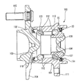
図1は磁気エンコーダが組み付けられた転がり軸受の一例を示す断面図であり、図2は磁気エンコーダ周辺の拡大図である。図示される転がり軸受10は、固定輪である外輪11と、回転輪(回転体)である内輪12と、外輪11及び内輪12により画成された環状隙間に転動自在に配置され且つ保持器14により円周方向に等間隔に保持された複数の転動体である玉13と、環状隙間の開口端部に配設された密封装置15と、内輪12の回転数を検出するための磁気エンコーダ20とを備えている。
(First embodiment)
FIG. 1 is a cross-sectional view showing an example of a rolling bearing with a magnetic encoder assembled therein, and FIG. 2 is an enlarged view around the magnetic encoder. The illustrated rolling
密封装置15は、外輪11の内周面に固定されたシール部材16と、シール部材16よりも開口端部外側に配置され、且つ内輪12の外周面に固定されたスリンガ17とを備えている。密封装置15は、シール部材16とスリンガ17との摺接によって、環状隙間の開口端部を塞ぎ、埃等の異物が軸受内部に侵入することを防止すると共に、軸受内部に充填された潤滑剤が軸受外部に漏洩することを防止している。尚、シール部材16は、断面略L字形の円環状に形成された芯金18により、同じく断面略L字形の円環状に形成されたゴムシール19を補強して構成されており、ゴムシール19の先端部を分岐して複数のシールリップ19a,19b,19cとし、スリンガ17の表面に摺接させている。
The sealing
一方、磁気エンコーダ20は、スリンガ17と、このスリンガ17の外側面(磁石接合面)に取り付けられ、上記磁性材料からなる磁極形成リング21とを有して構成されており、磁極形成リング21はスリンガ17を固定部材として内輪12に固定されている。
On the other hand, the
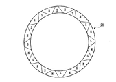
スリンガ17は、フェライト系ステンレス(SUS430等)、マルテンサイト系ステンレス(SUS410等)等の薄板からなり、内輪12に外嵌される円筒部17aと、円筒部17aの軸方向端部に湾曲部17bを介して連設され、半径方向外方に広がるように形成された鍔状のフランジ部17cを有する。磁極形成リング21は、図3に示すように、多極磁石であり、その周方向には、交互にN極とS極が形成されている。磁極形成リング21の極数は、70〜130極程度、好ましくは、90〜120極である。そして、この磁極形成リング27には磁気センサ(図示せず)が対面配置される。
The
(第2実施形態)
図4は、独立懸架式のサスペンションにおいて、従動輪を支持するための車輪支持用転がり軸受ユニット100への適用例を示す一部断面図である。
(Second Embodiment)
FIG. 4 is a partial cross-sectional view showing an application example to a wheel bearing rolling
転がり軸受ユニット100の内輪107は、ハブ103の内端部に形成した小径段部106に外嵌され、ハブ103の内端部を径方向外方にかしめ広げることにより形成したかしめ部109により、ハブ103に結合固定されている。そして、このハブ103と内輪107は回転輪(回転体)102を構成している。また、車輪は、このハブ103の外端部で、固定輪である外輪101の外端部から突出した部分に形成した取付フランジ104に円周方向に所定間隔で植設されたスタッド105によって、結合固定自在としている。これに対して外輪101は、その外周面に形成した結合フランジ111により、懸架装置を構成する、図示しないナックル等に結合固定自在としている。外輪101とハブ103及び内輪107との間には、保持器113によって案内された複数の転動体である玉112が周方向に転動自在に配置されている。
An
更に、外輪101の両端部内周面と、ハブ103の中間部外周面及び内輪106の内端部外周面との間には、それぞれ密封装置15,115が設けられる。これら各密封装置15,115は、外輪101の内周面とハブ103及び内輪106の外周面との間で、各玉112を設けた空間と外部空間とを遮断している。そして、この密封装置15を構成するスリンガ17の外側面に磁極形成リング21が取り付けられ、図1の形態と同様に、磁気エンコーダ20を構成している。なお、磁気エンコーダ20の軸方向外方には磁気センサ114が対向配置されており、磁束密度の変化を検出して車輪の回転速度を検出ことができる。
Further, sealing
(第3実施形態)
図5は同じく独立懸架式のサスペンションにおいて従動輪を支持するための車輪支持用転がり軸受ユニット100への適用例を示す一部断面図であり、図6は磁気エンコーダ周辺の拡大図である。尚、図4に示した車輪支持用転がり軸受ユニット100と同部材には同一の符号を付し、説明を省略する。
(Third embodiment)
FIG. 5 is a partial cross-sectional view showing an application example to the wheel-supporting
図示される車輪支持用転がり軸受ユニット100では、図4に示した車輪支持用転がり軸受ユニット100から密封装置15を取外し、その代わりにセンサキャップ115で全体を密封した構成となっている。センサキャップ115は、外輪101で囲まれた開口部を覆うように装着される樹脂製の蓋部材であり、センサ114はこのセンサキャップ115に固定されている。
The wheel supporting
(第4実施形態)
図7は、磁気エンコーダ20とセンサ114とがラジアル方向に対向した構成である。本実施形態の磁気エンコーダ20では、内輪107の内端部外周面に固定部材である円環状のスリンガ17が外嵌固定されており、内輪107から軸方向に延びるスリンガ17の内周面には、磁石部である磁極形成リング21が取り付けられている。また、外輪101の外周面には、静止部材であるカバー部材115が固定されており、カバー部材115に形成された開口部にはセンサ114が磁極形成リング21とラジアル方向に対向するようにして取り付けられている。
(Fourth embodiment)
FIG. 7 shows a configuration in which the
このような構成によれば、上記したようなアキシアル方向に対向する磁気エンコーダに比べて、同一スペースに対して被検出面の径を大きくできるので、ピッチ数が同一の場合、各ピッチ幅を大きくでき、製作しやすい。 According to such a configuration, the diameter of the detected surface can be increased with respect to the same space as compared with the magnetic encoder facing in the axial direction as described above. Therefore, when the number of pitches is the same, each pitch width is increased. It is easy to manufacture.
また、図示の例では、磁気エンコーダ20は軸端に配置されているが、磁気エンコーダ20は列間に配置することもできる。列間に配置する場合は、耐熱性を考慮して使用材料を適宜選定する。また、軸橋に配置する場合も、耐水性を考慮して使用材料を適宜選定する。更に、図の例では、センサ114が磁気エンコーダ20の内方に配置されているが、外方に配置してもよい。
In the illustrated example, the
本発明は、上述した実施形態に限定されるものでなく、適宜、変形、改良、等が可能である。例えば、図8に示すように、磁極形成リング21をV字状に着磁したラジアル対向タイプとすることができる。尚、V字状の磁極において、左右の傾き(α、β)は必ずしも同一でなくてもよく、V字をなす磁極の境界も直線に限らず曲線や、波線状でもよい。また、着磁方法も一極または複数極毎に着磁を繰り返す単極着磁、または一度で全ての磁極を着磁する多極着磁の何れもよい。
The present invention is not limited to the above-described embodiments, and modifications, improvements, and the like can be made as appropriate. For example, as shown in FIG. 8, the magnetic
また、磁極の形状は、図9に示すように、台形状でもよい。更には、上記した第4実施態様において、図11に示すような台形状に着磁した磁石部とすることもできる。 Further, the shape of the magnetic pole may be trapezoidal as shown in FIG. Furthermore, in the above-described fourth embodiment, a magnet portion magnetized in a trapezoidal shape as shown in FIG. 11 may be used.
以下に実施例及び比較例を挙げて本発明を更に明確にする。
(実施例1〜2、比較例1)
表1に示す如く、磁性体粉及びバインダを混練して磁性材料を調製した。また、SUS430製で、厚さ0.6mmの薄板を内径66mm、外径76mmの円環状に成形し、更に磁石接合面をショットブラストにより算術平均高さRa1.1〜1.3μmに粗面化してスリンガを作製し、その表面に、ノボラック型フェノール樹脂を主成分とする固形分30%のフェノール樹脂系接着剤(東洋化学研究所製「メタロックN−15」)をメチルエチルケトンで3倍に希釈して塗布し、室温で30分乾燥した後、120℃で30分乾燥器中に放置して半硬化状態とした。そして、スリンガをコアとして、磁性材料を内周部分をディスクゲートとするインサート成形した。成形後にゲートカットを行い、更に150℃で1時間2次加熱し、接着剤を完全硬化させた。得られた磁気エンコーダは、内径66mm、外径76mm、厚さ0.9mmであった。
The present invention will be further clarified by the following examples and comparative examples.
(Examples 1-2, Comparative Example 1)
As shown in Table 1, a magnetic material and a binder were kneaded to prepare a magnetic material. In addition, a SUS430-made thin plate with a thickness of 0.6 mm is formed into an annular shape with an inner diameter of 66 mm and an outer diameter of 76 mm, and the magnet joint surface is roughened to an arithmetic average height Ra of 1.1 to 1.3 μm by shot blasting. The slinger was prepared, and on its surface, a 30% solid phenol resin adhesive (“Metaloc N-15” manufactured by Toyo Chemical Laboratories) consisting mainly of novolak-type phenol resin was diluted three times with methyl ethyl ketone. After being coated at room temperature for 30 minutes, it was left in a dryer at 120 ° C. for 30 minutes to obtain a semi-cured state. Then, insert molding was performed with the slinger as the core and the magnetic material as the inner peripheral portion of the disk gate. The gate was cut after molding, and further heated at 150 ° C. for 1 hour to completely cure the adhesive. The obtained magnetic encoder had an inner diameter of 66 mm, an outer diameter of 76 mm, and a thickness of 0.9 mm.
作製した磁気エンコーダを各10個、熱衝撃試験機に入れ、120℃で30分保持及び−40℃で30分保持を一サイクルとする熱負荷を与え、50サイクル毎に磁石部を観察して亀裂の発生の有無を確認した。結果を表1に示す。 Put the 10 magnetic encoders into a thermal shock tester, apply a thermal load that holds 30 minutes at 120 ° C and 30 minutes at -40 ° C, and observe the magnet part every 50 cycles. The presence or absence of cracks was confirmed. The results are shown in Table 1.
表1から、変性熱可塑性ポリウレタン樹脂を配合したバインダを用いることで、材料自体の曲げたわみ量が大きくなり、耐亀裂性が向上し、それにより耐熱衝撃性が格段に良くなることがわかる。 From Table 1, it can be seen that the use of a binder containing the modified thermoplastic polyurethane resin increases the amount of bending deflection of the material itself, thereby improving the crack resistance, thereby significantly improving the thermal shock resistance.
10 転がり軸受ユニット
11 外輪
12 内輪
13 玉
14 保持器
15 密封装置
16 シール部材
17 スリンガ
20 磁気エンコーダ
DESCRIPTION OF
Claims (3)
前記バインダが、分子構造中にハードセグメントと、ポリ炭酸エステル、ポリカプロラクトン、ポリアジペートエステルから選ばれる何れかのソフトセグメントとを有する変性熱可塑性ポリウレタン樹脂、及び4,4´−(α、α−ジメチルベンジル)ジフェニルアミン、N,N´−ジフェニル−p−フェニレンジアミン、N−イソプロピル−N´−フェニル−p−フェニレンジアミン、N,N´−ジ−2−ナフチル−p−フェニレンジアミン、N,N´−ビス(1−メチルヘプチル)−p−フェニレンジアミン、N,N´−ビス(1,4−ジメチルペンチル)−p−フェニレンジアミン、N−(1,3−ジメチルブチル)−N´−フェニル−p−フェニレンジアミンから選ばれるアミン系酸化防止剤を含有し、かつ、該アミン系酸化防止剤の含有量がバインダとの合計量に対し0.5〜2.0質量%であることを特徴とする磁気エンコーダ。 In a magnetic encoder comprising a magnet portion formed in an annular shape with a magnetic material containing magnetic powder and a binder of the magnetic powder, and magnetized in multiple directions in the circumferential direction,
The binder includes a modified thermoplastic polyurethane resin having a hard segment and any soft segment selected from a polycarbonate, polycaprolactone, and polyadipate ester in a molecular structure, and 4,4 ′-(α, α− Dimethylbenzyl) diphenylamine, N, N′-diphenyl-p-phenylenediamine, N-isopropyl-N′-phenyl-p-phenylenediamine, N, N′-di-2-naphthyl-p-phenylenediamine, N, N '-Bis (1-methylheptyl) -p-phenylenediamine, N, N'-bis (1,4-dimethylpentyl) -p-phenylenediamine, N- (1,3-dimethylbutyl) -N'-phenyl containing an amine-based antioxidant selected from -p- phenylenediamine, and the inclusion of the amine-based antioxidant Magnetic encoder, characterized in that but 0.5 to 2.0% by weight relative to the total weight of the binder.
請求項1または2記載の磁気エンコーダが、前記回転輪に固定されていることを特徴とする転がり軸受ユニット。 In a rolling bearing unit comprising a fixed wheel, a rotating wheel, and a plurality of rolling elements disposed so as to be freely rollable in the circumferential direction between the fixed wheel and the rotating wheel.
3. A rolling bearing unit , wherein the magnetic encoder according to claim 1 is fixed to the rotating wheel .
Priority Applications (1)
| Application Number | Priority Date | Filing Date | Title |
|---|---|---|---|
| JP2006136644A JP4946172B2 (en) | 2006-05-16 | 2006-05-16 | Magnetic encoder and rolling bearing unit including the magnetic encoder |
Applications Claiming Priority (1)
| Application Number | Priority Date | Filing Date | Title |
|---|---|---|---|
| JP2006136644A JP4946172B2 (en) | 2006-05-16 | 2006-05-16 | Magnetic encoder and rolling bearing unit including the magnetic encoder |
Publications (3)
| Publication Number | Publication Date |
|---|---|
| JP2007309686A JP2007309686A (en) | 2007-11-29 |
| JP2007309686A5 JP2007309686A5 (en) | 2009-01-22 |
| JP4946172B2 true JP4946172B2 (en) | 2012-06-06 |
Family
ID=38842687
Family Applications (1)
| Application Number | Title | Priority Date | Filing Date |
|---|---|---|---|
| JP2006136644A Expired - Fee Related JP4946172B2 (en) | 2006-05-16 | 2006-05-16 | Magnetic encoder and rolling bearing unit including the magnetic encoder |
Country Status (1)
| Country | Link |
|---|---|
| JP (1) | JP4946172B2 (en) |
Families Citing this family (2)
| Publication number | Priority date | Publication date | Assignee | Title |
|---|---|---|---|---|
| DE102008033616A1 (en) * | 2008-07-17 | 2010-01-21 | Schaeffler Kg | Bearing and motor with a magnet |
| JP6439974B2 (en) * | 2015-03-31 | 2018-12-19 | 住友電気工業株式会社 | Bond magnet and method of manufacturing bond magnet |
Family Cites Families (4)
| Publication number | Priority date | Publication date | Assignee | Title |
|---|---|---|---|---|
| JP2004172381A (en) * | 2002-11-20 | 2004-06-17 | Nichia Chem Ind Ltd | Rare earth system magnetic powder and method for manufacturing the same |
| US20040183702A1 (en) * | 2003-01-23 | 2004-09-23 | Daniel Nachtigal | Magnetizable thermoplastic elastomers |
| JP2005057023A (en) * | 2003-08-04 | 2005-03-03 | Tdk Corp | Rare earth flexible sheet magnet and its manufacturing method |
| EP3495782B1 (en) * | 2004-01-22 | 2023-06-14 | Nsk Ltd. | Magnetic encoder and bearing |
-
2006
- 2006-05-16 JP JP2006136644A patent/JP4946172B2/en not_active Expired - Fee Related
Also Published As
| Publication number | Publication date |
|---|---|
| JP2007309686A (en) | 2007-11-29 |
Similar Documents
| Publication | Publication Date | Title |
|---|---|---|
| JP4993017B2 (en) | Magnetic encoder and rolling bearing unit including the magnetic encoder | |
| US7592798B2 (en) | Magnetic encoder and bearing | |
| JP4189696B2 (en) | Manufacturing method of magnetic encoder | |
| WO2006121052A1 (en) | Magnetic encoder and rolling bearing unit comprising magnetic encoder | |
| JP2008309717A (en) | Magnetic encoder and rolling bearing unit equipped with the magnetic encoder | |
| JP2009198420A (en) | Magnetic encoder, and rolling bearing unit equipped with magnetic encoder | |
| JP4968374B2 (en) | Magnetic encoder and rolling bearing unit including the magnetic encoder | |
| JP4946172B2 (en) | Magnetic encoder and rolling bearing unit including the magnetic encoder | |
| JP2006077804A (en) | Rolling bearing unit and its cage manufacturing method | |
| JP4432764B2 (en) | Manufacturing method of magnetic encoder and manufacturing method of rolling bearing unit for supporting wheel | |
| JP2005321307A (en) | Magnetic encoder, and rolling bearing unit equipped with the same | |
| JP5152273B2 (en) | Magnetic encoder and rolling bearing provided with the magnetic encoder | |
| JP4899500B2 (en) | Magnetic encoder and rolling bearing unit including the magnetic encoder | |
| JP2006170308A (en) | Rolling bearing unit for wheel | |
| JP4178412B2 (en) | Magnetic encoder, method of manufacturing the same, and rolling bearing unit | |
| JP4946257B2 (en) | Magnetic encoder and rolling bearing unit including the magnetic encoder | |
| JP2006017654A (en) | Encoder, its manufacturing method, and rolling bearing unit | |
| JP5958171B2 (en) | Magnetic encoder and rolling bearing unit including the magnetic encoder | |
| JP4706271B2 (en) | Magnetic encoder and rolling bearing unit | |
| JP4639936B2 (en) | Magnetic encoder and rolling bearing unit including the magnetic encoder | |
| JP2008304354A (en) | Magnetic encoder and rolling bearing unit with the same | |
| JP2022068532A (en) | Magnetic encoder and rolling bearing unit therewith | |
| JP2014098680A (en) | Magnetic encoder and rolling bearing unit including magnetic encoder |
Legal Events
| Date | Code | Title | Description |
|---|---|---|---|
| RD04 | Notification of resignation of power of attorney |
Free format text: JAPANESE INTERMEDIATE CODE: A7424 Effective date: 20071128 |
|
| A521 | Written amendment |
Free format text: JAPANESE INTERMEDIATE CODE: A523 Effective date: 20081201 |
|
| A621 | Written request for application examination |
Free format text: JAPANESE INTERMEDIATE CODE: A621 Effective date: 20081201 |
|
| A977 | Report on retrieval |
Free format text: JAPANESE INTERMEDIATE CODE: A971007 Effective date: 20101119 |
|
| A131 | Notification of reasons for refusal |
Free format text: JAPANESE INTERMEDIATE CODE: A131 Effective date: 20101124 |
|
| A521 | Written amendment |
Free format text: JAPANESE INTERMEDIATE CODE: A523 Effective date: 20110113 |
|
| A131 | Notification of reasons for refusal |
Free format text: JAPANESE INTERMEDIATE CODE: A131 Effective date: 20111206 |
|
| A521 | Written amendment |
Free format text: JAPANESE INTERMEDIATE CODE: A523 Effective date: 20120110 |
|
| TRDD | Decision of grant or rejection written | ||
| A01 | Written decision to grant a patent or to grant a registration (utility model) |
Free format text: JAPANESE INTERMEDIATE CODE: A01 Effective date: 20120207 |
|
| A01 | Written decision to grant a patent or to grant a registration (utility model) |
Free format text: JAPANESE INTERMEDIATE CODE: A01 |
|
| A61 | First payment of annual fees (during grant procedure) |
Free format text: JAPANESE INTERMEDIATE CODE: A61 Effective date: 20120220 |
|
| FPAY | Renewal fee payment (event date is renewal date of database) |
Free format text: PAYMENT UNTIL: 20150316 Year of fee payment: 3 |
|
| R150 | Certificate of patent or registration of utility model |
Free format text: JAPANESE INTERMEDIATE CODE: R150 |
|
| LAPS | Cancellation because of no payment of annual fees |