JP5198153B2 - Money handling system - Google Patents
Money handling system Download PDFInfo
- Publication number
- JP5198153B2 JP5198153B2 JP2008144839A JP2008144839A JP5198153B2 JP 5198153 B2 JP5198153 B2 JP 5198153B2 JP 2008144839 A JP2008144839 A JP 2008144839A JP 2008144839 A JP2008144839 A JP 2008144839A JP 5198153 B2 JP5198153 B2 JP 5198153B2
- Authority
- JP
- Japan
- Prior art keywords
- money
- money handling
- operation information
- user
- main body
- Prior art date
- Legal status (The legal status is an assumption and is not a legal conclusion. Google has not performed a legal analysis and makes no representation as to the accuracy of the status listed.)
- Active
Links
Images


Description
本発明は、互いに通信可能に構成された貨幣処理本体機と貨幣処理端末機とを備えた貨幣処理システムに関する。 The present invention relates to a money handling system including a money handling main body and a money handling terminal configured to communicate with each other.
実用新案登録2599232号公報には、現金管理装置が開示されている。当該現金管理装置では、金種ごとに収納庫が設けられ、また、収納庫毎に重量測定手段が設けられている。当該重量測定手段によって、金種ごとの重量が測定され、当該重量から金種ごとの棒金の本数が計算される。計算された棒金の本数は、測定日時と共に記憶され、表示される。重量の測定、棒金の本数の計算及び記憶は、現金管理装置が操作される度に(データ変更がある度に)行われる。 Japanese Utility Model Registration No. 2599232 discloses a cash management apparatus. In the cash management apparatus, a storage is provided for each denomination, and a weight measuring unit is provided for each storage. The weight for each denomination is measured by the weight measuring means, and the number of bars for each denomination is calculated from the weight. The calculated number of bars is stored and displayed together with the measurement date and time. The measurement of the weight, the calculation of the number of bars, and the storage are performed every time the cash management apparatus is operated (each time there is a data change).
このような装置は、入金の際に出納機内の現金が多くなって入らなくなった時に、利用されている。そして、その出納機内の現金が少なくなった時に、このような装置から逆に現金が取り出され、出納機に補充されている。 Such a device is used when the cash in the teller machine becomes too large to deposit when depositing. And when the cash in the teller machine decreases, cash is taken out from such a device and replenished to the teller machine.
このような装置を用いる場合、行員は、入出金を操作する時に、入金金額ないし出金金額を台帳などに記入する。 When such a device is used, the bank clerk enters the deposit amount or withdrawal amount in a ledger or the like when operating the deposit and withdrawal.
しかしながら、台帳に記入された入出金額と実際の入出金額とが異なっていると、問題が生じる。装置側では、実際の入出金額しか測定できないため、台帳に記入された入出金額が正しいかどうか精査できない。更に、このような装置は、誰が入出金の操作を行ったのかについて、管理を行っていない(行員であれば、誰でも収納庫を開閉することができる)。従って、例えば、行員が入出金額をごまかして不正を行うということが理論上可能である。 However, a problem arises if the deposit / withdrawal amount entered in the ledger is different from the actual deposit / withdrawal amount. Since only the actual deposit / withdrawal amount can be measured on the device side, it cannot be examined whether the deposit / withdrawal amount entered in the ledger is correct. Further, such an apparatus does not manage who has performed the deposit / withdrawal operation (anyone can open and close the storage if it is a clerk). Therefore, for example, it is theoretically possible for a bank clerk to cheat the deposit / withdrawal amount.
また、このような装置では、出納機と貨幣管理装置との在高の管理が連動されていないため、それらを総合的に管理することが困難である。 Moreover, in such an apparatus, since the management of the amount of money of a teller machine and a money management apparatus is not interlocked, it is difficult to manage them comprehensively.
一方、複数の自動取引装置の現金残高を集計することができる現金管理システムが、特許第2726550号公報に記載されている。このシステムでは、複数の自動取引装置の在高を総合的に管理することができる。 On the other hand, Japanese Patent No. 2726550 discloses a cash management system that can total the cash balances of a plurality of automatic transaction apparatuses. This system can comprehensively manage the stocks of a plurality of automatic transaction apparatuses.
しかしながら、この特許に記載されたシステムは、行員の入出金操作について新しい技術を提供するものではいない。
前記した通り、従来技術においては、誰が入出金の操作を行ったのかについて管理を行うことが困難であり、行員が入出金額をごまかして不正を行うということが理論上可能である。 As described above, in the prior art, it is difficult to manage who performed the deposit / withdrawal operation, and it is theoretically possible for the bank employee to cheat the deposit / withdrawal amount.
本発明は、このような課題を解決するためになされたもので、誰が入出金の操作を行ったのかについて容易に管理することができ、行員による誤操作及び不正を完全に防止することができるような貨幣処理システムを提供することを目的とする。 The present invention has been made to solve such a problem, and can easily manage who has made a deposit / withdrawal operation, and can completely prevent an erroneous operation and fraud by a bank employee. It aims at providing a simple money handling system.
本発明は、互いに通信可能に構成された貨幣処理本体機と貨幣処理端末機とを備えた貨幣処理システムであって、前記貨幣処理端末機は、使用者情報を取得する使用者情報取得手段と、前記使用者情報取得手段が取得した使用者情報と、前記貨幣処理本体機において許可者として設定された使用者の使用者情報と、の照合結果を得る使用者識別手段と、操作情報を取得する操作情報取得手段と、前記操作情報取得手段が取得した操作情報と、前記貨幣処理本体機において許可操作として設定された操作の操作情報と、の照合結果を得る操作識別手段と、前記使用者識別手段において得られた照合結果、及び、前記操作識別手段において得られた照合結果に基づいて、前記貨幣処理端末機を使用可能状態と使用不可能状態との間で切り換える制御手段と、を有していることを特徴とする貨幣処理システムである。 The present invention is a money handling system including a money handling main body and a money handling terminal configured to communicate with each other, wherein the money handling terminal includes user information obtaining means for obtaining user information, and , User identification means for obtaining a collation result between the user information acquired by the user information acquisition means and the user information of the user set as an authorized person in the money handling main body, and operation information is acquired. Operation information acquisition means, operation information acquired by the operation information acquisition means, and operation identification means for obtaining a comparison result between operation information set as a permitted operation in the money handling main body, and the user Based on the collation result obtained by the identification unit and the collation result obtained by the operation identification unit, the money processing terminal is switched between the usable state and the unusable state. A money handling system characterized in that it comprises a means.
本発明によれば、貨幣処理端末機を使用可能状態にするための条件として、使用者情報の照合のみならず、操作情報の照合をも採用していることにより、使用者の誤操作を効果的に防止することができる一方、操作記録を管理することも極めて容易である。 According to the present invention, as a condition for making the money handling terminal usable, not only user information collation but also operation information collation is adopted, so that the user's erroneous operation is effective. On the other hand, it is very easy to manage operation records.
好ましくは、前記操作情報は、入出金操作毎に設定される操作情報である。すなわち、1回の入出金操作に対応して、1個の操作情報が設定されることが好ましい。 Preferably, the operation information is operation information set for each deposit / withdrawal operation. That is, it is preferable that one piece of operation information is set corresponding to one deposit / withdrawal operation.
具体的には、例えば、前記操作情報は、入出金操作毎に設定される操作番号である。操作番号は、それ自体から操作内容が判読できないような、暗号の如き番号であることが好ましい。この場合、貨幣処理端末機の側には、操作情報取得手段として、例えばそのような操作番号を入力する入力装置が用意される。 Specifically, for example, the operation information is an operation number set for each deposit / withdrawal operation. It is preferable that the operation number is an encryption number that cannot be read from the operation content itself. In this case, for example, an input device for inputting such an operation number is prepared on the money processing terminal side as operation information acquisition means.
そして、好ましくは、前記貨幣処理本体機は、通信機能を利用して、前記操作情報取得手段において得られた操作情報(例えば操作番号)に対応する入出金データを前記貨幣処理端末機に転送する機能を有している。この場合、操作内容である入出金データについて、使用者(操作者)が手入力等する必要がない。従って、使用者(操作者)の誤操作が生じる可能性が、顕著に低減される。 Preferably, the money handling main body uses the communication function to transfer the deposit / withdrawal data corresponding to the operation information (for example, the operation number) obtained in the operation information acquisition means to the money handling terminal. It has a function. In this case, the user (operator) does not need to manually input the deposit / withdrawal data as the operation content. Therefore, the possibility of erroneous operation by the user (operator) is significantly reduced.
また、例えば、前記貨幣処理本体機が、許可者に対して操作情報を提供する機能を有する。より具体的には、例えば、前記貨幣処理本体機が、許可者に対して操作情報を提供するために、操作情報が表示されたレシートを発行するレシート発行装置を有する。この場合、使用者(操作者)が、そのレシートに表示された操作情報を暗記するか、あるいは、そのレシートを貨幣処理端末機まで持参して、当該操作情報を所定の操作情報取得装置に取得させる。 Further, for example, the money handling main body has a function of providing operation information to the permitter. More specifically, for example, the money handling main body has a receipt issuing device for issuing a receipt on which operation information is displayed in order to provide operation information to an authorized person. In this case, the user (operator) memorizes the operation information displayed on the receipt or brings the receipt to the money processing terminal and acquires the operation information to a predetermined operation information acquisition device. Let
その他、前記貨幣処理本体機は、通信機能を利用して前記貨幣処理端末機の在高データを確認及び/または精査するための在高データ遠隔確認部を有していることが好ましい。 In addition, it is preferable that the money handling main body has a balance data remote confirmation unit for confirming and / or examining the balance data of the money handling terminal using a communication function.
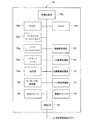
図1は、本発明の一実施の形態を示すシステム概略図である。図1に示す貨幣処理システム300は、互いに通信可能に構成された出納機100と貨幣管理装置200(現金バスとも呼ばれる)とを備えている。出納機100が、貨幣処理本体機として機能し、貨幣管理装置200が、貨幣処理端末機として機能するようになっている。出納機100及び貨幣管理装置200は、それぞれ、上位の貨幣処理装置及び下位の貨幣処理装置、として理解されてもよい。すなわち、例えば、両者が同一仕様の貨幣処理装置によって構成されていてもよい。また、1台の出納機100に対して、複数台の貨幣管理装置200が通信可能に設けられてもよい。
FIG. 1 is a system schematic diagram showing an embodiment of the present invention. A
図2は、出納機100の外観を示す斜視図である。図3は、出納機100の機能ブロック図である。
FIG. 2 is a perspective view showing the appearance of the
図2に示すように、出納機100は、束紙幣を処理する束紙幣処理部P1及びバラ紙幣を処理するバラ紙幣処理部P2からなる紙幣処理装置11と、バラ硬貨を処理するバラ硬貨処理装置12と、包装硬貨を処理する包装硬貨処理装置13と、を備えている。図2中、21は束紙幣を出金する束紙幣出金口、22はバラ紙幣を出金するバラ紙幣出金口、23は包装硬貨を出金する包装硬貨出金口、24はバラ硬貨を出金するバラ硬貨出金口、である。
As shown in FIG. 2, the
また、この出納機100は、現金以外の有価証券類を投入する現金外ボックス14、出納機100全体を制御する制御部15、制御部15に各種の指示を与えるキーボード式操作部16、制御部15による指示に従って印字処理を行う外部プリンタ18、を備えている。外部プリンタ18が、レシート発行装置として機能するようになっている。本実施の形態では、許可者に対して操作情報を提供するために、操作情報に対応する4桁の数字が表示されたレシートが発行されるようになっている。
Further, the
制御部15は、その一部として、営業員及び管理者とのインターフェースとしての表示部15aと、営業員及び管理者が所持するIDカードの内容を読み取るIDカードリーダ15bと、を備えている。本実施の形態においてはIDカードリーダが用いられているが、これに限られず、公知の顔認証端末や、指に流れる静脈を認証するもの等、使用者本人を認証するものであれば何を用いても構わない。
The
また、図3に示すように、この制御部15は、各種プログラム及びデータを格納したROM15d、プログラムのロード領域やプログラム実行時における作業領域となるRAM15e、フレキシブルディスクに対してデータを読み書きするフレキシブルディスクドライブ15f、各種プログラム及びデータを記憶したハードディスクドライブ15g、ROM15dやハードディスクドライブ15g内に格納されたプログラムを実行等して出納機100全体を制御する制御本体部15c、を備えている。
As shown in FIG. 3, the
また、図3に示すように、出納機100は、貨幣管理装置200との間でデータ通信を行う通信インターフェース(通信IF)19を備えている。これにより、出納機100(貨幣処理本体機)と貨幣管理装置200(貨幣処理端末機)とは、互いに通信可能となっている。
As shown in FIG. 3, the
図4は、貨幣管理装置200の外観を示す斜視図である。図4に示すように、貨幣管理装置200は、1万円紙幣を収納保管する第1紙幣収納ドロア211と、その他の金種の紙幣を収納保管する第2紙幣収納ドロア212と、100円と10円と1円の硬貨を収納保管する第1硬貨収納ドロア213と、500円と50円と5円の硬貨を収納保管する第2硬貨収納ドロア214と、現金以外の有価証券類も投入することができる予備収納ドロア215と、を有している。
FIG. 4 is a perspective view showing the external appearance of the
また、この貨幣管理装置200は、貨幣管理装置200の全体を制御する制御装置225(制御手段)と、制御装置225に各種の指示を与えるキーボード式操作部226と、使用者(営業員及び管理者)とのインターフェースとしての表示部227と、収納庫に貨幣を入出する操作を行う使用者が所持するIDカードの内容を読み取るIDカードリーダ228と、を備えている。
In addition, the
IDカードの内容、すなわち、IDカードに記憶されたID情報が、使用者情報の一態様であり、IDカードリーダ228が、使用者情報取得手段の一態様である。図4の例では、接触式のIDカードリーダ228が採用されているが、非接触式のカードリーダが採用されてもよい。また、IDカードリーダの他に、出納機100と同様、顔認証や静脈認証等を利用するための機器が採用されてもよい。
The content of the ID card, that is, the ID information stored in the ID card is an aspect of the user information, and the
図5は、貨幣管理装置200の第2紙幣収納ドロア212の斜視図である。図5に示すように、第2紙幣収納ドロア212には、3種類の金種の紙幣の束が、規則正しく収納保管される。図5の例では、第2紙幣収納ドロア212の内部に、4つの紙幣保管容器221〜224が配置されており、各容器毎に、収納保管される紙幣の金種が決められている。
FIG. 5 is a perspective view of the second
図6は、貨幣管理装置200の第2硬貨収納ドロア214の斜視図である。図6に示すように、第2硬貨収納ドロア214には、3種類の金種の棒金状態の硬貨が、規則正しく収納保管される。図6の例では、第2硬貨収納ドロア214の内部に、3つの硬貨保管容器241〜243が配置されており、各容器毎に、収納保管される硬貨の金種が決められている。
FIG. 6 is a perspective view of the second
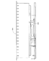
図7は、図6の硬貨保管容器241の側面概略図である。図7に示すように、硬貨保管容器241の底面には、硬貨保管容器241内に収納保管される硬貨の重量を測定するための測定手段として、ロードセル261が設けられている。ロードセルの構成の詳細については十分に知られていると思われるので、ここでの説明は省略する。他の硬貨保管容器242、243、並びに、紙幣保管容器221〜224についても、同様にロードセルが設けられている。このような構成によって、各金種毎に、収納保管されている貨幣の重量が測定されるようになっている。
FIG. 7 is a schematic side view of the
その他、図8は、予備収納庫(予備ドロア)215の斜視図である。図8に示すように、予備収納庫215には、硬貨予備収納部251及び紙幣予備収納部252の他に、現金以外の有価証券類を投入することができる空スペース253が設けられている。
In addition, FIG. 8 is a perspective view of the preliminary storage (preliminary drawer) 215. As shown in FIG. 8, the
続いて、図9は、貨幣管理装置200の制御装置225の機能ブロック図である。制御装置225は、各種プログラム及びデータを格納したROM225d、プログラムのロード領域やプログラム実行時における作業領域となるRAM225e、各種プログラム及びデータを記憶したハードディスクドライブ225g、ROM225dやハードディスクドライブ225g内に格納されたプログラムを実行等して貨幣管理装置200全体を制御する演算制御部225c、を備えている。
Next, FIG. 9 is a functional block diagram of the
演算制御部225c(演算手段)は、各金種毎に対応して設けられたロードセル(重量測定手段)に接続されており、ロードセルの出力値に基づいて、収納保管された貨幣の重量に対応する貨幣の金額を算出できるようになっている。そして、ハードディスクドライブ225gが、演算制御部225c(記憶手段)によって算出された貨幣の金額を記憶するようになっている。
The
本実施の形態では、ここで、IDカードリーダ228が読み取るID情報(使用者情報)も、算出された貨幣の金額(入出操作後の収納保管金額)と対応させた態様で、ハードディスクドライブ225gに記憶されるようになっている。
In the present embodiment, the ID information (user information) read by the
本実施の形態では、更に、キーボード式操作部226(入力手段)において、収納庫に対して入出される貨幣の金額が入力されるようになっており、演算制御部225cが、精査手段として、ロードセルの出力値から算出された金額と、キーボード式操作部226で入力された金額と、を精査できるようになっている。
In the present embodiment, furthermore, the amount of money entered and exited from the storage is input at the keyboard type operation unit 226 (input unit), and the
また、図9に示すように、貨幣管理装置200は、出納機100との間でデータ通信を行う通信インターフェース(通信IF)229を備えている。これにより、貨幣管理装置200(貨幣処理端末機)と出納機100(貨幣処理本体機)とは、互いに通信可能となっている。
As shown in FIG. 9, the
また、本実施の形態の制御装置225は、ロック制御手段として、各ドロア211〜215に設けられた開閉電磁ロック211m〜215mに接続されていて、各ドロア211〜215を、貨幣の入出が可能な開状態と貨幣の入出が不可能なロック状態との間で切替えることができるようになっている。
Further, the
この切替制御の条件として、本実施の形態では、使用者照合が採用されている。具体的には、例えば、予め許可者として設定された使用者のID情報(使用者情報)が、ハードディスクドライブ225gに記憶されていて、IDカードリーダ228(使用者情報取得手段)が読み取ったID情報が、使用者識別手段としての演算制御部225cによって、許可者のID情報に対して照合されるようになっている。照合の結果がYESである、すなわち、IDカードリーダ228が読み取ったID情報が、予め許可者として設定された使用者のID情報に合致する場合にのみ、制御装置225は、開閉電磁ロック211m〜215mを制御して、貨幣の入出が可能な開状態とすることができる。
As a condition for this switching control, user verification is employed in the present embodiment. Specifically, for example, ID information (user information) of a user set in advance as an authorized person is stored in the
別の切替制御の条件として、本実施の形態では、使用者照合に加えて、操作情報の照合も採用され得る。操作情報とは、例えば入出金操作毎に設定される操作情報であり、通常は入出金の金種及び金額のデータであるが、入出操作の手順に関するデータを含むこともあり得る。操作情報の照合の具体的態様としては、例えば、予め許可操作として設定された操作の操作情報が、出納機100から通信機能を利用して例えばRAM225eに転送記憶され、一方、使用者によって、操作情報に対応する4桁の操作番号が、キーボード式操作部226(操作情報取得手段)で入力され得る。そして、入力された4桁の操作番号の情報が、操作識別手段としての演算制御部225cによって、転送記憶された操作情報に対して照合され得る。この場合、照合の結果がYESである、すなわち、入力された4桁の操作番号が、転送記憶された許可操作の操作情報に合致する場合にのみ、制御装置225は、開閉電磁ロック211m〜215mを制御して、貨幣の入出が可能な開状態とすることができる。この態様においては、好適なことに、入出操作の具体的内容に即して、開閉電磁ロック211m〜215mを個別に制御することが可能である。具体的には、入出対象である金種を収納するドロアのみを、開状態に切り替えることができる。更には、複数のドロアが同時には開状態にならないように、各ドロアを順に開状態に切り換えるという制御態様を採用することも可能である。
As another switching control condition, in this embodiment, in addition to user verification, verification of operation information may be employed. The operation information is, for example, operation information set for each deposit / withdrawal operation, and is usually data of deposit / withdrawal denomination and amount, but may also include data regarding the procedure of deposit / withdrawal operation. As a specific mode of collation of operation information, for example, operation information of an operation set in advance as a permitted operation is transferred and stored in the
その他、本実施の形態では、貨幣管理装置200(貨幣処理端末機)と出納機100(貨幣処理本体機)とが互いに通信可能であることを利用して、更に以下のような構成が採用されている。 In addition, in this Embodiment, the following structures are further employ | adopted using the money management apparatus 200 (money processing terminal machine) and the teller machine 100 (money processing main body machine) mutually communicating. ing.
出納機100(貨幣処理本体機)の制御部15は、通信機能を利用して貨幣管理装置200(貨幣処理端末機)の在高データを確認及び/または精査するための在高データ遠隔確認部として機能できるように構成されている。具体的には、出納機100(貨幣処理本体機)の制御部15が、通信インターフェース(通信IF)19及び通信インターフェース(通信IF)229を介して、精査手段である演算制御部225cを制御できるようになっている。
The
また、出納機100(貨幣処理本体機)の制御部15は、通信インターフェース(通信IF)19及び通信インターフェース(通信IF)229を介して、開閉電磁ロック211m〜215mをも制御できるようになっている。
The
具体的には、通信インターフェース(通信IF)229が、開閉電磁ロック211m〜215m(ロック装置)を制御して開状態とするためのロック解除信号を受信するロック解除信号受信部として機能するようになっており、これに対応して、出納機100(貨幣処理本体機)の制御部15が、所定の条件下で、ロック解除信号を通信インターフェース(通信IF)19を介して通信インターフェース(通信IF)229に対して送信するように構成されている。
Specifically, the communication interface (communication IF) 229 functions as an unlock signal receiving unit that receives an unlock signal for controlling the open / close
このように、開閉電磁ロック211m〜215mの制御が出納機100の側で行われる場合には、出納機100の側で制御の具体的条件を設定ないし調整することができるため、各ドロアの開閉操作の管理、ひいては貨幣の入出操作の管理を、より集中的に行うことが可能となる。
In this way, when the control of the open / close
この場合、開閉電磁ロック211m〜215mは、それが開状態とされてから各ドロアの開閉操作が行われた後、自動的にロック状態となるように構成されることが好ましい。あるいは、開閉電磁ロック211m〜215mは、それが開状態とされてから所定時間が経過した後、自動的にロック状態となるように構成されることが好ましい。
In this case, it is preferable that the open / close
更に好ましくは、通信インターフェース(通信IF)229が、開閉電磁ロック211m〜215m(ロック装置)を制御してロック状態とするためのロック信号を受信するロック信号受信部として機能するようになっており、これに対応して、出納機100(貨幣処理本体機)の制御部15が、所定の条件下で、ロック信号を通信インターフェース(通信IF)19を介して通信インターフェース(通信IF)229に対して送信するように構成され得る。
More preferably, the communication interface (communication IF) 229 functions as a lock signal receiving unit that receives a lock signal for controlling the open / close
この場合、貨幣管理装置200は、各ドロア211〜215の開状態から閉状態への変化を検知する閉動作検知装置211c〜215cを更に備えて、当該閉動作検知装置による検知信号が出納機100に送信され、出納機100が当該検知信号を受信した際に前記ロック信号を送信するようになっていることが好ましい。この場合、各ドロアのロック制御の管理を、出納機100側でより集中的に行うことが可能となる。
In this case, the
あるいは、開閉電磁ロック211m〜215mは、開状態とされてから所定時間が経過しても依然として開状態である場合に、自動的にロック状態となるように構成されていることが好ましい。また、貨幣管理装置200は、各ドロア211〜215の閉状態から開状態への変化を検知する開動作検知装置211o〜215oを更に備えることが好ましい。
Alternatively, it is preferable that the open / close
その他、各ドロア211〜215の開状態が所定時間以上継続している際に報知信号を出力する報知装置(アラーム装置)280が更に設けられている。
In addition, a notification device (alarm device) 280 that outputs a notification signal when the
また、図9における鍵検知部290とは、貨幣管理装置200の電源off時にドロアの開閉が行われる際に、そのことを検知するセンサ装置である。これは、少なくとも当該技術分野においては新しい技術であるが、本発明の概念とは直接には関連しないので、ここでの説明は省略する。
A
次に、以上に説明した貨幣処理システムの動作例について、フローチャートを参照しながら説明する。 Next, an operation example of the money handling system described above will be described with reference to a flowchart.
図10は、出納機100の側での入出操作準備プロセスの一例のフローチャートである。まず、IDカードリーダ15bによって、出納機100の操作者のID情報が読み取られる(STEP11)。当該ID情報に基づいて、その操作者が、出納機100の操作許可者であるか否かが識別される(STEP12)。
FIG. 10 is a flowchart of an example of an entry / exit operation preparation process on the
操作許可者であれば、出納機100の操作メニューが表示部15aに表示される(STEP13)。その表示を見ながら、操作者(操作許可者)は、キーボード式操作部16を用いて操作内容を入力する(STEP14)。ここで、本例では、セキュリティの一層の向上のために、暗証番号入力を求める(STEP15)。
If the user is an authorized person, the operation menu of the
暗証番号の照合の後、操作者(操作許可者)は、キーボード式操作部16を用いて、入出操作の詳細を入力する(STEP16)。具体的には、入出対象の金種や金額(束数あるいは本数でもよい)のデータが入力される。その後、操作者による入力完了キーの操作によって、入力完了が検知される(STEP17)。出納機100は、入力された入出操作の詳細に対して、操作情報としての操作番号(連動番号と呼ぶこともある)を特定(発行)し、当該操作番号と実際の入出操作の詳細な内容との対応付けをハードディスク15gに記憶する(STEP18)。また、レシート発行装置18から、当該操作番号が表示されたレシートを発行する(STEP19)。
After collating the passwords, the operator (operation authorized person) inputs details of the entry / exit operation using the keyboard type operation unit 16 (STEP 16). Specifically, data of the denomination and amount of money (the number of bundles or the number of bundles) may be entered. Thereafter, the input completion is detected by the operation of the input completion key by the operator (STEP 17). The
図11は、現金管理装置200における入出操作準備プロセスの一例のフローチャートである。まず、IDカードリーダ228によって、現金管理装置200の操作者のID情報が読み取られる(STEP21)。当該ID情報に基づいて、その操作者が、現金管理装置200の操作許可者であるか否かが識別される(STEP22)。
FIG. 11 is a flowchart of an example of an entry / exit operation preparation process in the
操作許可者であれば、現金管理装置200の操作メニューが表示部227に表示される(STEP23)。その表示を見ながら、操作者(操作許可者)は、キーボード式操作部226を用いて操作内容を入力する(STEP24)。
If it is an operation authorized person, the operation menu of the
まず、出納機100との連動処理が選択される場合について先に説明する。
First, the case where the interlocking process with the
連動処理が選択されると、本例では、セキュリティの一層の向上のために、暗証番号入力を求める(STEP25)。 When the interlocking process is selected, in this example, in order to further improve security, a password input is requested (STEP 25).
暗証番号の照合の後、操作者(操作許可者)は、キーボード式操作部226を用いて、出納機100にて発行された操作番号(連動番号)を入力する(STEP26)。これにより、現金管理装置200は、通信機能を利用して、出納機100のハードディスク15gに記憶された対応付け情報に基づいて、当該操作番号に対応する入出操作の詳細情報(処理キューと呼ばれる:入出操作対象である金種ないし金額のデータの他、ドロアの開閉手順のデータが含まれ得る)をピックアップし(STEP27)、その一部の情報(全部でもよい)を操作者の確認のために表示する(STEP28)。確認の後、操作者による入力完了キーの操作によって、入出準備完了が検知される(STEP29)。
After collation of the personal identification number, the operator (operation authorized person) uses the keyboard
次に、出納機100との非連動処理が選択される場合について説明する。この場合のプロセスは、従来の現金管理装置のプロセスと略同様である。
Next, the case where the non-interlocking process with the
非連動処理が選択されると、本例では、セキュリティの一層の向上のために、暗証番号入力を求める(STEP125)。 When the non-interlocking process is selected, in this example, in order to further improve the security, a password input is requested (STEP 125).
暗証番号の照合の後、操作者(操作許可者)は、キーボード式操作部226を用いて、入出操作の詳細を入力する(STEP126)。具体的には、入出対象の金種や金額(束数あるいは本数でもよい)のデータが入力される。その後、操作者による入力完了キーの操作によって、入力完了が検知される(STEP127)。 After collation of the passwords, the operator (operation authorized person) inputs details of the entry / exit operation using the keyboard type operation unit 226 (STEP 126). Specifically, data of the denomination and amount of money (the number of bundles or the number of bundles) may be entered. Thereafter, the input completion is detected by the operation of the input completion key by the operator (STEP 127).
続いて、図12は、現金管理装置200におけるドロア開閉プロセスの一例のフローチャートである。ここでは、入出操作の詳細情報(処理キュー)に基づいて、開状態にされるドロアの順序が決定されているものとする。
Next, FIG. 12 is a flowchart of an example of a drawer opening / closing process in the
まず、最初に開状態になるドロアに対応する電磁開閉ロックのロックが解除される(STEP31)。ロック解除制御は、現金管理装置200内の制御部225によって行われてもよいし、通信機能を介して出納機100の制御部15によって行われてもよい。
First, the lock of the electromagnetic open / close lock corresponding to the drawer that is initially opened is released (STEP 31). The unlock control may be performed by the
ロックが解除されたドロアは、操作者によって開放され、貨幣の入出操作が行われる。ここで、ロックが解除されてから所定時間が経過してもドロアが開放されない場合には、報知装置280がアラームをならすようになっている(STEP32)。また、ドロアが開けられてから所定時間が経過しても閉じられない場合にも、報知装置280がアラームをならすようになっている(STEP33)。
The unlocked drawer is opened by the operator, and a money insertion / exit operation is performed. Here, if the drawer is not released even after a predetermined time has passed since the lock was released, the
貨幣の入出操作が順調に終了して、操作者がドロアを閉じると、当該ドロアに対応する電磁開閉ロックがロック状態にされる(STEP34)。このロック制御も、現金管理装置200内の制御部225によって行われてもよいし、通信機能を介して出納機100の制御部15によって行われてもよい。
When the money entry / exit operation ends smoothly and the operator closes the drawer, the electromagnetic open / close lock corresponding to the drawer is locked (STEP 34). This lock control may also be performed by the
そして、他のドロア(金種)に対する入出処理が残って入れば、次に開状態になるドロアに対して処理が繰り返され、他のドロア(金種)に対する入出処理が無ければ、入出処理は終了して精査プロセスに行く。 If the entry / exit processing for the other drawer (denomination) remains and enters, the process is repeated for the next drawer to be opened. If there is no entry / exit processing for the other drawer (denomination), the entry / exit processing is performed. Finish and go to the scrutiny process.
図13は、現金管理装置200における精査プロセスの一例のフローチャートである。
FIG. 13 is a flowchart of an example of a scrutiny process in the
この精査プロセスは、出納機100との連動処理においては操作番号の入力を介して得られた入出操作の詳細情報に基づいて、非連動処理においてはキーボード式操作部226での入力を介して得られた入出操作の詳細情報に基づいて、実際に入出された貨幣の金額がそれら情報に合致しているか否かを判別するプロセスである。実際に入出された貨幣の金額については、ロードセルを用いた貨幣重量の測定結果から算出される(STEP41)。
This scrutiny process is obtained based on the detailed information of the input / output operation obtained through the input of the operation number in the interlocking process with the
精査の結果、金額が合致する場合には、その取引内容(操作内容と操作者との双方の情報を含む)がハードディスク225gに記憶される(STEP42)。必要な場合には、不図示のプリンタから、処理結果が印字されてもよい(STEP43)。
If the amounts match as a result of the scrutiny, the transaction content (including information on both the operation content and the operator) is stored in the
精査の結果、金額が合致しない場合には、合致しない金種(の全て)に対して、図12に示したドロア開閉プロセスが再実行される(STEP44)。 If the amount does not match as a result of the scrutiny, the drawer opening / closing process shown in FIG. 12 is re-executed for all of the types that do not match (STEP 44).
以上に説明したように、本実施の形態によれば、現金管理装置200を使用可能(入出操作可能)状態にするための条件として、使用者のID情報の照合のみならず、操作情報の照合をも採用していることにより、使用者の誤操作を効果的に防止することができる一方、操作記録を管理することも極めて容易である。
As described above, according to the present embodiment, not only verification of the user ID information but also verification of the operation information as a condition for making the
特に、操作情報として、入出金操作毎に設定(発行)される4桁(3桁以上が好ましい)の操作番号(連動番号)を採用しているため、取り扱いが容易である一方で、当該操作番号から操作内容が知られる畏れもない。 In particular, the operation information employs a 4-digit operation number (preferably 3 digits or more) set (issued) for each deposit / withdrawal operation. There is no doubt that the operation content is known from the number.
また、操作番号に対応する入出金データが出納機100から現金管理装置200に転送されることにより、入出金データ自体を使用者が手入力等する必要がなく、従って、使用者による誤操作が効果的に防止される。
In addition, since the deposit / withdrawal data corresponding to the operation number is transferred from the
また、本実施の形態によれば、貨幣の入出操作の度に精査プロセスを実施することによって、入出操作に誤りがないか入出操作毎に精査することができる。これにより、使用者の誤操作を効果的に防止することができる一方、操作記録(入出記録)を入出操作毎に管理することも極めて容易である。更に、本実施の形態によれば、入出操作に対応付けて使用者情報をも容易に管理することができる。 In addition, according to the present embodiment, it is possible to examine each input / output operation for an error in the input / output operation by performing a scrutinization process for each money input / output operation. Thereby, the user's erroneous operation can be effectively prevented, while it is also very easy to manage the operation record (entry / exit record) for each entry / exit operation. Furthermore, according to the present embodiment, user information can be easily managed in association with the entry / exit operation.
また、本実施の形態によれば、出納機100の側でロック解除信号及び/またはロック信号の送信条件を設定ないし調整することができる。この場合、貨幣の入出操作の管理を集約的に行うことが可能である。これは特に、複数台の現金管理装置200を含むシステムにおいて有効である。
Further, according to the present embodiment, the unlocking signal and / or the transmission condition of the lock signal can be set or adjusted on the
なお、前述の説明では、使用者のID情報の照合と操作情報の照合とが現金管理装置200の側で行われているが、データが実際に照合される場所は特に限定されない。すなわち、これらの照合は、現金管理装置200の側で行われてもよいし、出納機100の側で行われてもよいし、それらに接続された他のハードウェアを利用して行われてもよい。また、照合のための各データの転送のタイミングについても、公知の種々の態様から適宜に選択されて採用される。
In the above description, the collation of the user ID information and the collation of the operation information are performed on the
その他、精査プロセスのために用いられる収納貨幣量の測定手段としては、ロードセルのような重量センサの他、収納保管された貨幣の空間占有状態を測定するセンサが用いられてもよい。収納保管された貨幣は、その量に応じて、保管容器の内部における占有体積が当然に異なるため、貨幣の空間占有状態(例えば保管容器のどの部位まで貨幣によって占有されているか、あるいは、保管されている束紙幣の束数ないし包装硬貨の本数(どれだけ入っているか))を検出することによって、保管容器内に収納されている収納貨幣の量を得ることができる。そのようなセンサとしては、例えばLEDからなるラインセンサが用いられる。 In addition to the weight sensor such as a load cell, a sensor for measuring the space occupation state of stored and stored money may be used as the means for measuring the stored money amount used for the scrutiny process. Depending on the amount of the stored money, the occupied volume in the storage container naturally varies, so that the space occupied state of the money (for example, up to which part of the storage container is occupied or stored by money) By detecting the number of bundled banknotes or the number of wrapping coins (how many are contained), the amount of stored coins stored in the storage container can be obtained. As such a sensor, for example, a line sensor composed of LEDs is used.
100 出納機
200 現金管理装置
211 第1紙幣収納ドロア
212 第2硬貨収納ドロア
213 第1紙幣収納ドロア
214 第2硬貨収納ドロア
215 予備収納庫
211m〜215m 開閉電磁ロック
221〜224 紙幣保管容器
241〜243 硬貨保管容器
261 ロードセル
100
Claims (6)
前記貨幣処理本体機は、使用者に対して、入金または出金の操作毎に操作情報を発行するようになっており、
前記貨幣処理端末機は、
使用者情報を取得する使用者情報取得手段と、
前記使用者情報取得手段が取得した使用者情報と、許可者として設定された使用者の使用者情報と、の照合結果を得る使用者識別手段と、
前記貨幣処理本体機によって使用者に対して入金または出金の操作毎に発行された操作情報を取得する操作情報取得手段と、
前記操作情報取得手段が取得した操作情報と、予め前記貨幣処理本体機において入金または出金の操作毎に設定された操作情報と、の照合結果を得る操作識別手段と、
前記使用者識別手段において得られた照合結果、及び、前記操作識別手段において得られた照合結果に基づいて、前記貨幣処理端末機を使用可能状態と使用不可能状態との間で切り換える制御手段と、
を有していることを特徴とする貨幣処理システム。 A money processing main body that stores money and withdraws or deposits money; and a money processing terminal that is communicably connected to the money processing main body and stores and stores money separately from the money processing main body, A money handling system comprising:
The money handling main body is configured to issue operation information to the user for each deposit or withdrawal operation.
The money handling terminal is:
User information acquisition means for acquiring user information;
User identification means for obtaining a collation result between user information acquired by the user information acquisition means and user information of a user set as an authorized person;
Operation information acquisition means for acquiring operation information issued for each operation of depositing or withdrawing to the user by the money handling main body ;
Operation identification means for obtaining a collation result between the operation information acquired by the operation information acquisition means and operation information set in advance for each operation of depositing or withdrawing in the money handling main body machine,
Control means for switching the money handling terminal between the usable state and the unusable state based on the collation result obtained by the user identifying means and the collation result obtained by the operation identifying means; ,
A money handling system characterized by comprising:
前記操作情報取得手段は、前記操作番号を入力する入力装置である
ことを特徴とする請求項1に記載の貨幣処理システム。 The operation information is an operation number set for each deposit / withdrawal operation,
The money handling system according to claim 1 , wherein the operation information acquisition unit is an input device that inputs the operation number.
ことを特徴とする請求項2に記載の貨幣処理システム。 The money handling main body has a function of transferring deposit / withdrawal data corresponding to the operation information obtained in the operation information acquisition means to the money handling terminal using a communication function. The money handling system according to claim 2 .
ことを特徴とする請求項1乃至3のいずれかに記載の貨幣処理システム。 The money handling system according to any one of claims 1 to 3 , wherein the money handling main body has a function of providing operation information to a permitter.
ことを特徴とする請求項4に記載の貨幣処理システム。 5. The money according to claim 4 , wherein the money handling machine has a receipt issuing device for issuing a receipt on which operation information is displayed in order to provide operation information to an authorized person. Processing system.
ことを特徴とする請求項1乃至4のいずれかに記載の貨幣処理システム。 2. The money handling main unit includes a money status remote confirmation unit for confirming and / or examining the money status data of the money handling terminal using a communication function. The money handling system according to any one of 1 to 4 .
Priority Applications (1)
| Application Number | Priority Date | Filing Date | Title |
|---|---|---|---|
| JP2008144839A JP5198153B2 (en) | 2008-06-02 | 2008-06-02 | Money handling system |
Applications Claiming Priority (1)
| Application Number | Priority Date | Filing Date | Title |
|---|---|---|---|
| JP2008144839A JP5198153B2 (en) | 2008-06-02 | 2008-06-02 | Money handling system |
Related Child Applications (1)
| Application Number | Title | Priority Date | Filing Date |
|---|---|---|---|
| JP2013020782A Division JP5558597B2 (en) | 2013-02-05 | 2013-02-05 | Money handling system |
Publications (3)
| Publication Number | Publication Date |
|---|---|
| JP2009294709A JP2009294709A (en) | 2009-12-17 |
| JP2009294709A5 JP2009294709A5 (en) | 2012-07-26 |
| JP5198153B2 true JP5198153B2 (en) | 2013-05-15 |
Family
ID=41542886
Family Applications (1)
| Application Number | Title | Priority Date | Filing Date |
|---|---|---|---|
| JP2008144839A Active JP5198153B2 (en) | 2008-06-02 | 2008-06-02 | Money handling system |
Country Status (1)
| Country | Link |
|---|---|
| JP (1) | JP5198153B2 (en) |
Families Citing this family (2)
| Publication number | Priority date | Publication date | Assignee | Title |
|---|---|---|---|---|
| JP5492688B2 (en) * | 2010-07-14 | 2014-05-14 | ローレルバンクマシン株式会社 | Money handling system |
| JP6291905B2 (en) * | 2014-02-27 | 2018-03-14 | 富士電機株式会社 | Money processing equipment |
Family Cites Families (5)
| Publication number | Priority date | Publication date | Assignee | Title |
|---|---|---|---|---|
| JPS62205467A (en) * | 1986-03-05 | 1987-09-10 | Fujitsu Ltd | Maintenance system for automatic machine by id card |
| JP2726550B2 (en) * | 1990-05-28 | 1998-03-11 | 株式会社東芝 | Cash management system |
| JPH10255165A (en) * | 1997-03-14 | 1998-09-25 | Oki Electric Ind Co Ltd | System for registering data in automated equipment |
| JP4089775B2 (en) * | 2002-03-01 | 2008-05-28 | グローリー株式会社 | Teller machine processing system |
| JP4872343B2 (en) * | 2005-12-28 | 2012-02-08 | 沖電気工業株式会社 | Medium issuing device and medium issuing system |
-
2008
- 2008-06-02 JP JP2008144839A patent/JP5198153B2/en active Active
Also Published As
| Publication number | Publication date |
|---|---|
| JP2009294709A (en) | 2009-12-17 |
Similar Documents
| Publication | Publication Date | Title |
|---|---|---|
| JP5430898B2 (en) | Money management device | |
| JP5203146B2 (en) | Money management system and money management method | |
| JP5290631B2 (en) | Money management device | |
| JP5260197B2 (en) | Money management device | |
| JP5717542B2 (en) | Money management system | |
| JP5198153B2 (en) | Money handling system | |
| JP4897104B2 (en) | Money management device | |
| JP5405052B2 (en) | Money handling system | |
| JP5866417B2 (en) | Money management device | |
| JP4970614B2 (en) | Money management device | |
| JP4865074B2 (en) | Money management device | |
| JP5242310B2 (en) | Money management device | |
| JP6074493B2 (en) | Money handling system | |
| JP6101338B2 (en) | Money management device | |
| JP5869033B2 (en) | Money handling system | |
| JP5558597B2 (en) | Money handling system | |
| JP5260611B2 (en) | Money management device | |
| JP5593422B2 (en) | Money management device | |
| JP5778994B2 (en) | Money management apparatus and money management system | |
| JP5340678B2 (en) | Money management device | |
| JP5335336B2 (en) | Money management device | |
| JP6324135B2 (en) | Money management device | |
| JP5591974B2 (en) | Money management device | |
| JP5497124B2 (en) | Money management system and money management method | |
| JP2010072742A (en) | Device for managing currency |
Legal Events
| Date | Code | Title | Description |
|---|---|---|---|
| A621 | Written request for application examination |
Free format text: JAPANESE INTERMEDIATE CODE: A621 Effective date: 20110516 |
|
| A521 | Written amendment |
Free format text: JAPANESE INTERMEDIATE CODE: A523 Effective date: 20120612 |
|
| A871 | Explanation of circumstances concerning accelerated examination |
Free format text: JAPANESE INTERMEDIATE CODE: A871 Effective date: 20120612 |
|
| A975 | Report on accelerated examination |
Free format text: JAPANESE INTERMEDIATE CODE: A971005 Effective date: 20120628 |
|
| A131 | Notification of reasons for refusal |
Free format text: JAPANESE INTERMEDIATE CODE: A131 Effective date: 20120807 |
|
| A521 | Written amendment |
Free format text: JAPANESE INTERMEDIATE CODE: A523 Effective date: 20120926 |
|
| A131 | Notification of reasons for refusal |
Free format text: JAPANESE INTERMEDIATE CODE: A131 Effective date: 20121106 |
|
| A521 | Written amendment |
Free format text: JAPANESE INTERMEDIATE CODE: A523 Effective date: 20121218 |
|
| TRDD | Decision of grant or rejection written | ||
| A01 | Written decision to grant a patent or to grant a registration (utility model) |
Free format text: JAPANESE INTERMEDIATE CODE: A01 Effective date: 20130111 |
|
| A61 | First payment of annual fees (during grant procedure) |
Free format text: JAPANESE INTERMEDIATE CODE: A61 Effective date: 20130206 |
|
| FPAY | Renewal fee payment (event date is renewal date of database) |
Free format text: PAYMENT UNTIL: 20160215 Year of fee payment: 3 |
|
| R150 | Certificate of patent or registration of utility model |
Ref document number: 5198153 Country of ref document: JP Free format text: JAPANESE INTERMEDIATE CODE: R150 Free format text: JAPANESE INTERMEDIATE CODE: R150 |
|
| R157 | Certificate of patent or utility model (correction) |
Free format text: JAPANESE INTERMEDIATE CODE: R157 |