JP5197166B2 - Image forming apparatus - Google Patents
Image forming apparatus Download PDFInfo
- Publication number
- JP5197166B2 JP5197166B2 JP2008149048A JP2008149048A JP5197166B2 JP 5197166 B2 JP5197166 B2 JP 5197166B2 JP 2008149048 A JP2008149048 A JP 2008149048A JP 2008149048 A JP2008149048 A JP 2008149048A JP 5197166 B2 JP5197166 B2 JP 5197166B2
- Authority
- JP
- Japan
- Prior art keywords
- sheet
- image forming
- image
- curl
- conveyance path
- Prior art date
- Legal status (The legal status is an assumption and is not a legal conclusion. Google has not performed a legal analysis and makes no representation as to the accuracy of the status listed.)
- Expired - Fee Related
Links
Images


Classifications
-
- G—PHYSICS
- G03—PHOTOGRAPHY; CINEMATOGRAPHY; ANALOGOUS TECHNIQUES USING WAVES OTHER THAN OPTICAL WAVES; ELECTROGRAPHY; HOLOGRAPHY
- G03G—ELECTROGRAPHY; ELECTROPHOTOGRAPHY; MAGNETOGRAPHY
- G03G15/00—Apparatus for electrographic processes using a charge pattern
- G03G15/22—Apparatus for electrographic processes using a charge pattern involving the combination of more than one step according to groups G03G13/02 - G03G13/20
- G03G15/23—Apparatus for electrographic processes using a charge pattern involving the combination of more than one step according to groups G03G13/02 - G03G13/20 specially adapted for copying both sides of an original or for copying on both sides of a recording or image-receiving material
- G03G15/231—Arrangements for copying on both sides of a recording or image-receiving material
- G03G15/232—Arrangements for copying on both sides of a recording or image-receiving material using a single reusable electrographic recording member
- G03G15/234—Arrangements for copying on both sides of a recording or image-receiving material using a single reusable electrographic recording member by inverting and refeeding the image receiving material with an image on one face to the recording member to transfer a second image on its second face, e.g. by using a duplex tray; Details of duplex trays or inverters
- G03G15/235—Arrangements for copying on both sides of a recording or image-receiving material using a single reusable electrographic recording member by inverting and refeeding the image receiving material with an image on one face to the recording member to transfer a second image on its second face, e.g. by using a duplex tray; Details of duplex trays or inverters the image receiving member being preconditioned before transferring the second image, e.g. decurled, or the second image being formed with different operating parameters, e.g. a different fixing temperature
-
- G—PHYSICS
- G03—PHOTOGRAPHY; CINEMATOGRAPHY; ANALOGOUS TECHNIQUES USING WAVES OTHER THAN OPTICAL WAVES; ELECTROGRAPHY; HOLOGRAPHY
- G03G—ELECTROGRAPHY; ELECTROPHOTOGRAPHY; MAGNETOGRAPHY
- G03G15/00—Apparatus for electrographic processes using a charge pattern
- G03G15/65—Apparatus which relate to the handling of copy material
- G03G15/6555—Handling of sheet copy material taking place in a specific part of the copy material feeding path
- G03G15/6573—Feeding path after the fixing point and up to the discharge tray or the finisher, e.g. special treatment of copy material to compensate for effects from the fixing
- G03G15/6576—Decurling of sheet material
-
- G—PHYSICS
- G03—PHOTOGRAPHY; CINEMATOGRAPHY; ANALOGOUS TECHNIQUES USING WAVES OTHER THAN OPTICAL WAVES; ELECTROGRAPHY; HOLOGRAPHY
- G03G—ELECTROGRAPHY; ELECTROPHOTOGRAPHY; MAGNETOGRAPHY
- G03G2215/00—Apparatus for electrophotographic processes
- G03G2215/00362—Apparatus for electrophotographic processes relating to the copy medium handling
- G03G2215/00535—Stable handling of copy medium
- G03G2215/00662—Decurling device
Landscapes
- Physics & Mathematics (AREA)
- General Physics & Mathematics (AREA)
- Separation, Sorting, Adjustment, Or Bending Of Sheets To Be Conveyed (AREA)
- Counters In Electrophotography And Two-Sided Copying (AREA)
- Conveyance By Endless Belt Conveyors (AREA)
- Control Or Security For Electrophotography (AREA)
Description
本発明は、電子写真方式によって可視画像を形成する複写機、プリンタ、記録画像表示装置、ファクシミリなどの電子写真画像形成装置(以下、画像形成装置という)に関する。 The present invention relates to an electrophotographic image forming apparatus (hereinafter referred to as an image forming apparatus) such as a copying machine, a printer, a recorded image display apparatus, and a facsimile machine that forms a visible image by an electrophotographic system.
コピー、プリンタ機能を有する複合機や、ファクシミリなどにおいては、電子写真方式の画像形成装置が広く利用されている。 An electrophotographic image forming apparatus is widely used in a multifunction machine having a copy and printer function, a facsimile, and the like.
電子写真方式を利用した画像形成装置にあっては、感光体上あるいは転写体上に担持されている可視像を普通紙等のシートに転写して記録画像を得るようにしている。このため、感光体あるいは転写体から可視像を転写されたシートは、定着器に搬送されて可視像の定着を受けた後に画像形成装置の外に排出される。 In an image forming apparatus using an electrophotographic system, a visible image carried on a photosensitive member or a transfer member is transferred to a sheet such as plain paper to obtain a recorded image. For this reason, the sheet on which the visible image has been transferred from the photosensitive member or the transfer member is conveyed to the fixing device and is fixed to the visible image, and then discharged out of the image forming apparatus.
ここで、シートの裏面側にも画像形成を行う場合は、図4に示すように、表面に転写、定着されたシートを反転パス110に引き込んだ後、スイッチバックさせて、両面搬送パス111に導いて画像形成部に再給送するようにしている。また、シートの同一面上に複数回画像形成を行う場合は表面に転写、定着されたシートを反転させずに、そのまま多重搬送パス112に引き込み画像形成部に再給送するようにしている。なお、シートを両面搬送パスもしくは多重搬送パスに導くための搬送路は一般的に湾曲しており、さらに本体サイズを抑えるためには出来る限り大きな曲率で湾曲している方が有利である。
Here, when image formation is performed also on the back side of the sheet, as shown in FIG. 4, after the sheet transferred and fixed on the front surface is drawn into the
ところが、定着器を通過する際に加えられる熱や圧力によりシートにはカールが生じてしまう場合があり、カールしているシートは搬送中にジャムや角折れの原因となる。また、カールしたシートは、カールがない状態の最初の画像形成時のシートの姿勢と異なった姿勢で転写部へ送り込まれてしまうため、転写部での電界の影響でトナー像を乱すことにより画像不良を起こし、また、飛散トナー等を発生させてしまうことがある。 However, the sheet may be curled due to heat or pressure applied when passing through the fixing device, and the curled sheet may cause jamming or corner breakage during conveyance. In addition, the curled sheet is sent to the transfer unit in a posture different from the posture of the first image forming state without curling. Therefore, the toner image is disturbed due to the influence of the electric field in the transfer portion. It may cause defects and generate scattered toner and the like.
そこで、特許文献1に示す画像形成装置では、図4に示すように、定着器101でカールが生ずる。これを除去するために、定着器101の直後にカール補正器102を設けている。このカール補正器102はシートにカールをつけるようにすることで、定着器101で生じたカールを除去する。そして、カールが除去された状態でシートを両面搬送パス111もしくは多重搬送パス112に送り込むようにしている。
Therefore, in the image forming apparatus shown in
この画像形成装置では、定着器101の直後の排出パス、両面搬送パス、及び、多重搬送パスの分岐前にカール補正器102が配置されている。このため、裏面への転写・定着時と同一面上への転写・定着時とにかかわらず、シートのカール補正器102への進入時点での同一方向にカール形成が行われる。
In this image forming apparatus, a
図4のカール補正器102は、シートに下カール(搬送方向両端が中央部よりも下向きのカール)を形成する。この場合、同一面に複数回の画像形成を多重画像形成の場合には、カール補正器102にて下カールが形成されたシートは、再度画像転写部に搬送されたときに下カールが形成された状態となる。
The
一方、表裏両面に画像形成を行う両面画像形成の場合はシートの表裏が反転される。このため、シートが画像転写部へ再度送られる際に、1回目の画像形成面の裏面への画像形成時と同一面への画像形成時ではカール方向は逆向きとなる。例えば、シート表面への画像形成で下カールが形成されたシートの裏面に画像形成を行う場合は、シートが表裏反転されるために再度画像転写部に搬送されたシートは上カール(搬送方向両端が中央部よりも上向きのカール)が形成された状態で進入することになる。 On the other hand, in the case of double-sided image formation in which image formation is performed on both sides, the front and back sides of the sheet are reversed. For this reason, when the sheet is fed again to the image transfer unit, the curl direction is reversed when the image is formed on the same surface as the first image formation on the back surface of the image formation surface. For example, when image formation is performed on the back side of a sheet on which the lower curl is formed in the image formation on the sheet surface, the sheet conveyed to the image transfer unit again because the sheet is reversed, the upper curl (both ends in the conveyance direction) Is entered in a state in which a curl upward from the center portion is formed.
ここで、画像転写部へシートが進入する際に、シート端部がトナー像が形成された像担持体に近づく方向にカールが形成されていると(図4の構成にあっては、シートに上カールが形成されている場合)、転写不良が起こるおそれがある。これは、トナー像転写ニップ部に進入する前にシートの先端が像担持体である中間転写体に接触して搬送性が悪化するからである。例えば、中間転写体がシートの搬送パスの本体上方に配置されている構成では、シートが2次転写ニップ部に送られる際に、シートに上カールが形成されていると転写不良が起こる。 Here, when the sheet enters the image transfer portion, if the end of the sheet is curled in a direction approaching the image carrier on which the toner image is formed (in the configuration of FIG. If the upper curl is formed), transfer failure may occur. This is because the leading edge of the sheet comes into contact with the intermediate transfer member, which is an image carrier, before entering the toner image transfer nip portion, and the transportability is deteriorated. For example, in the configuration in which the intermediate transfer member is disposed above the main body of the sheet conveyance path, when the sheet is sent to the secondary transfer nip portion, if the upper curl is formed on the sheet, transfer failure occurs.
特許文献1に記載の画像形成装置において、シートの1回目の画像形成面の裏面に画像を形成する時にシートが2次転写ニップ部に送られる際に下カールとなるようにカール補正器を設定した場合を考える。この場合、シートの1回目の画像形成面の同一面に画像を形成するときには、シートが2次転写ニップ部に送られる際に上カールとなるために、転写不良が起こるおそれがある。
In the image forming apparatus described in
上述したように、従来の画像形成装置では、シートの同一面へ多重に画像を形成するモードと、両面に画像を形成するモードの両方のモードを有する場合に、シートに生ずるカールにより、ジャム、角折れ、画像不良が発生するおそれがあった。 As described above, in a conventional image forming apparatus, when there are both a mode for forming multiple images on the same side of the sheet and a mode for forming images on both sides, a jam, There is a risk of corner breakage and image defects.
本発明は上記点に鑑みてなされたものであり、その目的は、シートの同一面へ多重に画像を形成するモードと、両面に画像を形成するモードの両方のモードを有する場合に、それらの両モードで、シートのジャム、角折れ、画像不良の発生を防止し得る画像形成装置を提供するものである。 The present invention has been made in view of the above points, and an object of the present invention is to provide a mode in which both a mode for forming multiple images on the same surface of a sheet and a mode for forming images on both sides are provided. It is an object of the present invention to provide an image forming apparatus capable of preventing occurrence of sheet jamming, corner bending, and image defect in both modes.
上記課題を解決するための本発明における代表的な構成は、シートの同一面上に画像を複数回形成する多重画像形成モードと、シートの表裏両面に画像を形成する両面画像形成モードとを有する画像形成装置であって、画像を担持する像担持体と、前記像担持体よりもシート搬送方向の下流に配置され、前記シートに画像を定着させる定着手段と、前記両面画像形成モードが選択されている場合に、前記定着手段によって前記シートの端部が前記像担持体から離間する方向にカールしたときに、前記シートの表裏が反転された状態で前記シートの端部が前記像担持体から離間する方向にカールするように補正するカール補正手段と、前記多重画像形成モードが選択されている場合に前記シートを搬送するための多重画像形成用搬送パスと、前記両面画像形成モードが選択されている場合に前記シートを搬送するための両面画像形成用搬送パスと、を具備し、前記カール補正手段は、前記両面画像形成用搬送パスと前記多重画像形成用搬送パスとの共通部分以外の部分の前記両面画像形成用搬送パスに設けられていることを特徴とする。 A typical configuration in the present invention for solving the above problems has a multiple image forming mode in which an image is formed a plurality of times on the same surface of a sheet, and a double-sided image forming mode in which images are formed on both the front and back sides of the sheet. An image forming apparatus , wherein an image carrier that carries an image, a fixing unit that is disposed downstream of the image carrier in a sheet conveyance direction and fixes an image on the sheet, and the double-sided image formation mode are selected. If it is, when the end portion of the sheet is curled in a direction away from said image bearing member by said fixing means, an end portion of the sheet from the image carrier in a state where the front and back are reversed in the sheet and Carl correcting means for correcting to curl in a direction away, the conveying path for multiple image formation for conveying the sheet when the multiple image forming mode is selected, prior to Anda conveyance path for double-sided image formation for conveying the sheet when the double-sided image forming mode is selected, the curl correction means, transport the multiple image forming and the duplex image forming transport path The double-sided image forming conveyance path is provided in a portion other than the common portion with the path .
本発明の画像形成装置によれば、シートの同一面上に複数回の画像形成が可能であり、且つ表裏両面に画像形成を行える画像形成装置において、両方の画像形成モードでシートのジャム、角折れ、及び、画像不良の発生を防ぐことができる。 According to the image forming apparatus of the present invention, in an image forming apparatus capable of forming an image a plurality of times on the same surface of the sheet and forming images on both the front and back surfaces, the jam and corner of the sheet in both image forming modes. Occurrence of folding and image defects can be prevented.
以下、図面を参照しつつ、本発明の実施形態について詳細に説明する。 Hereinafter, embodiments of the present invention will be described in detail with reference to the drawings.
〔第1実施形態〕
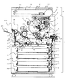
図1は本発明の第1の実施形態である画像形成装置の概略構成図である。この画像形成装置は、電子写真フルカラー画像形成装置であり、上部にデジタルカラー画像リーダ部R、下部にデジタルカラー画像プリンタ部Pを有する。
[First Embodiment]
FIG. 1 is a schematic configuration diagram of an image forming apparatus according to a first embodiment of the present invention. This image forming apparatus is an electrophotographic full-color image forming apparatus, and has a digital color image reader unit R in the upper part and a digital color image printer part P in the lower part.
[画像形成装置の全体構成]
デジタルカラー画像リーダ部Rにおいて、31は原稿台ガラス、32は原稿台ガラス31に対して開閉可能な原稿圧着板である。原稿台ガラス31上にカラー原稿Oを画像面下向きで所定の載置基準に従って載置し、その上に原稿圧着板32を被せることでカラー原稿Oをセットする。
[Overall configuration of image forming apparatus]
In the digital color image reader unit R, 31 is a document platen glass, and 32 is a document crimping plate that can be opened and closed with respect to the
原稿圧着板32を原稿自動送り装置にして、原稿台ガラス31上にシート状原稿を自動的に送る構成にすることもできる。この場合には、両面原稿の自動送り装置とすることもできる。33は原稿台ガラス31の下面に沿って移動駆動される移動光学系である。この移動光学系33により原稿台ガラス31上のカラー原稿Oの下向き画像面が光学的に走査される。その原稿走査光が光電変換素子(固体撮像素子)であるCCD34に結像されてRGB(レッド・グリーン・ブルー)の三原色で色分解読取りされる。読取られたRGBの各信号が画像処理部(図示しない)に入力される。
The
デジタルカラー画像プリンタ部Pは、1ドラムのロータリ現像構成及び中間転写構成を有する電子写真画像形成機構である。このデジタルカラー画像プリンタ部Pの動作概略は次の通りである。 The digital color image printer unit P is an electrophotographic image forming mechanism having a one-drum rotary development configuration and an intermediate transfer configuration. The outline of the operation of the digital color image printer unit P is as follows.
像担持体としての電子写真感光体ドラム(以下、感光ドラムという)1上に、画像信号を、レーザースキャナ3にて、露光画像として形成する。
An image signal is formed as an exposure image by a
感光ドラム1上に形成された露光画像上に、複数の現像器からなるロータリ現像装置4により1色毎にトナー像が順次形成される。ロータリ現像装置4は、現像ロータリ41の内部に所望の色の現像剤を収容しており、トナーカートリッジ部(図示しない)から現像剤としてのトナーを必要時随時補給するための補給パイプ400を備えている。
On the exposed image formed on the
感光ドラム1上の各色のトナー像を更に中間転写ベルト(以下、ベルトという)5上に1色毎に1次転写することを繰り返して、ベルト5上に未定着の必要色のトナー像を合成形成する。その後、このトナー像を一括でシートS上に2次転写し、次いで定着してフルカラー画像形成物を出力するものである。
By repeating primary transfer of each color toner image on the
以下に、更に詳しく説明する。感光ドラム1は矢印の反時計方向に所定の速度で回転駆動され、その表面が帯電器2により所定の極性・電位に一様に帯電される。その帯電処理面がレーザースキャナ3によりレーザー走査露光される。
This will be described in more detail below. The
レーザースキャナ3は、レーザー出力部、ポリゴンミラー、結像レンズ、折り返しミラー等を有し、画像処理部(図示しない)から入力される画像情報信号に対応して変調されたレーザー光(光信号)を出力して、回転する感光ドラム1の帯電処理面を走査露光する。これにより、感光ドラム1の面に走査露光パターンに対応した静電潜像が形成される。尚、画像情報信号は、デジタルカラー画像リーダ部Rから読み込まれた画像情報以外にも、パソコンなどの外部機器より電送される画像情報より合成、形成されたものでも構わない。
The
その静電潜像がロータリ現像装置4によりトナー像として現像される。ロータリ現像装置4は、現像ロータリ41に各々の色現像剤(トナー)を収容させた複数の現像器401を装着したものである。現像ロータリ41が所定の制御タイミングで所定の角度だけ図示矢印方向に回転されることによって、各々の現像器401が感光ドラム1と対向する現像位置に切り換えられて配置される。現像位置において、感光ドラム1と、現像器401側の現像スリーブとの距離(SD距離)が或る決められた範囲内に保たれる。
The electrostatic latent image is developed as a toner image by the
ベルト5は可撓性を有する誘電材製のエンドレスベルトであり、複数のローラ5a〜5g間に懸回張設されている。ベルト5の外面はローラ5b,5c間において感光ドラム1に接触している。その接触部が1次転写ニップ部T1である。1次転写ニップ部T1において、ベルト5の感光ドラム1側と反対側に1次転写ローラ6が配設されており、ベルト5の内面に接している。1次転写ローラ6には、所定の制御タイミングでトナーと逆極性の1次転写電圧が印加される。ベルト5は、例えばローラ5aを駆動ローラとして、感光ドラム1の回転速度とほぼ同じ速度で矢印の時計方向に回転駆動される。
The
まず、感光ドラム1に対して、1色目のトナー像が、上述した帯電・露光・現像の画像形成工程により形成される。そして、そのトナー像が1次転写ニップ部T1においてベルト5上に転写される。ベルト5に転写されないで感光ドラム1の面に残った1次転写残トナーはドラムクリーニング装置7により感光ドラム面から除去される。ドラムクリーニング装置7により清掃された感光ドラム1は繰り返して画像形成に供される。同様の画像形成工程が2色目〜N色目について随時繰り返えされる。これによりベルト5上に、各現像色のトナー像の順次重畳転写により未定着のトナー画像が合成されて形成される。
First, a toner image of the first color is formed on the
一方、所定の制御タイミングで給送カセット81〜84、或いはマルチ手差しトレイ85の複数の給送部のうち、予め選択された給送部の給送ローラ11が駆動される。これにより、その給送部に収容されたシート状の紙などのシートSが1枚分離されて送り出されて搬送パス13からレジストローラ14へ送られる。レジストローラ14は、シートSの斜行補正と、ベルト5からシートSへのトナー像の2次転写のタイミングを制御するもので、給送部側から給送されたシートSの先端を受け止めて一旦停止させる。
On the other hand, the feeding
2次転写ローラ15は、ベルト5の複数のローラ5a〜5gの内のローラ5gを対向ローラとしてローラ5gに対してベルト5を挟んで圧接した第1状態と、ベルト5の外面から離間した第2状態とに加圧制御機構(図示せず)により切り換えられ脱着制御される。2次転写ローラ15は常時はベルト5の外面から離間した第2状態に切り換えられて保持されている。尚、第1状態に切り換えられることで、ベルト5の外面との間に2次転写ニップ部T2が形成される。2次転写ローラ15は所定の制御タイミングで第1状態に切り変えられる。また、レジストローラ14の位置で一旦停止されているシートSは所定の制御タイミングでレジストローラ14から再給送され、第1状態に切り変えられた2次転写ローラ15とベルト5との間の2次転写ニップ部T2に導入される。この際、シートSが上向きのカールの場合、シート先端がニップ部入り口に引っかかる、或いは入り難い及び、搬送され難いことなどが原因の転写不良が生じる。
The
そして、シートSはこの2次転写ニップ部T2を挟持搬送されていく。その間、2次転写ローラ15には所定の2次転写電圧が印加されて、ベルト5上の複数色からなるトナー像がシートS上に静電的に一括転写され、シートS上には未定着のトナー像が形成(転写)される。
Then, the sheet S is nipped and conveyed through the secondary transfer nip portion T2. In the meantime, a predetermined secondary transfer voltage is applied to the
シートSに転写されないでベルト5の面に残った2次転写残トナーはベルトクリーニング装置16によりベルト面から除去される。ベルトクリーニング装置16により清掃されたベルト5は繰り返して画像形成に供される。ベルトクリーニング装置16は、常時はベルト5の外面から離間した状態に保持され、2次転写ニップ部T2にてベルト5からシートSに対するトナー像の2次転写がなされるときに、所定の制御タイミングにてベルト5の外面に接触した状態に切り換えられる。
The secondary transfer residual toner not transferred to the sheet S and remaining on the surface of the
2次転写ニップ部T2を出たシートSはベルト5の面から分離して、搬送ベルトユニット17によって定着手段である定着器18へ搬送され、未定着トナー像は熱及び圧力によりシートS上に融着されて定着画像となる。定着器18はシートSに下向きのカールを形成する。定着器18を出たシートSは搬送パス19を通って排出トレイ20上に排出される。
The sheet S exiting the secondary transfer nip T2 is separated from the surface of the
21,35,37,38,40,25は、再度、シートSに画像を転写、定着させる際のシート搬送パスである。このシート搬送パスは、両面画像形成モードや多重画像形成モードが選択された場合に、定着器18を出た、片面画像形成済みのシート又は1回目画像形成済みのシートを表裏反転させて、もしくは表裏反転させないで、2次転写ニップ部T2へ再搬送する。
21, 35, 37, 38, 40, and 25 are sheet conveyance paths for transferring and fixing the image on the sheet S again. This sheet conveyance path is obtained by inverting the front and back of the sheet on which the single-sided image has been formed or the sheet on which the first image has been formed, which has exited from the fixing
[カール補正手段]
シート搬送パス40にはカール補正手段としてのカール補正器23が設けられている。このカール補正器23は、搬送されるシートにカールを形成するものであり、駆動回転可能な支持ローラ23a,23bに支持されたベルト23cに付勢ローラ23dが回転可能に当接している。シートはベルト23cと付勢ローラ23dの間を搬送される際に、ベルト23c側に凹むように搬送されてカールが形成される。
[Curl correction means]
The
このカール補正器23が配設されているシート搬送パス40は、後述するように多重画像形成モードが選択されているときはシート搬送経路とならず、両面画像形成モードが選択されている場合にシート搬送経路となる。このため、カール補正器23は両面画像形成モードが選択されている場合に定着器18によってシートに生じたカールを補正するカール補正手段となる。
The
[多重画像形成モード]
以下多重画像形成モードについて詳細に説明する。多重画像形成モードは、シートSの片方の面に画像が複数回形成される。定着器18を出たシートSは、シート搬送方向を切り替える切替部材26にて、図中下方の搬送パス21へ導かれ、図中右下方の搬送パス35に搬送される。搬送パス35の図中右方には、切替部材36が配設されている。切替部材36が図1の下方に回動した場合は、シートSは搬送パス37に搬送される。また、切替部材36が図中上方に回動した場合は、シートSは搬送パス38に搬送される。
[Multiple image forming mode]
Hereinafter, the multiple image forming mode will be described in detail. In the multiple image forming mode, an image is formed on one side of the sheet S a plurality of times. The sheet S exiting the fixing
多重画像形成モードにおいては、切替部材36が図中下方に回動することで、シートSは搬送パス37に搬送され、主走査方向(奥・手前方向)のシート位置を横レジ検知センサ24にて検出され、搬送パス25へと送られる。すなわち、シートSは搬送パス21,35,37,25を通過することになり、これらの搬送パスにより多重画像形成用搬送パスが構成される。
In the multiple image forming mode, the switching
多重画像形成モードでは、シートSは搬送パス40に配設されたカール補正手段としてのカール補正器23を通過せず、1回目画像形成後に再度、2次転写ニップ部T2に送られるまでの間に一度もカール補正されない。そのため、シートSは定着器18により形成された下カールの状態で2次転写ニップ部T2に再度送られるため、転写不良が起こらない。
In the multiple image forming mode, the sheet S does not pass through the curl corrector 23 as the curl correcting unit disposed in the
また、横レジ検知センサ24にて検知されたシート端部の位置情報は、1回目の画像の主走査方向の書き込み位置の補正用に用いられる。このため、多重搬送パス中にシートSの主走査方向の位置に変動が生じても、1回目の画像とほぼ同じ主操作位置に画像を形成することが可能となる。
Further, the position information of the sheet edge detected by the lateral
その後、シートSは再度定着器を通過し、搬送パス19を経由し、排出ローラ200にて、排出トレイ20上に排出される。
Thereafter, the sheet S passes through the fixing device again, and is discharged onto the
[両面画像形成モード]
続いて、両面画像形成モードについて詳細に説明する。定着器18を出たシートSは、切替部材26にて、図中下方の搬送パス21へ導かれ、図中右下方の搬送パス35に搬送される。搬送パス35の図中右方に配設された切替部材36が図中上方に回動することで、シートSは搬送パス38に搬送される。シートSの後端を反転センサ39が検知すると、所定時間後に反転ローラ22は搬送を止めて逆回転し、シートSを逆方向に搬送する。反転ローラ22の逆回転時に切替部材27を作動させることにより、シートSは図中右方の搬送パス40に搬送され、さらに搬送パス25に搬送される。すなわち、搬送パス21,35,38,40,25は両面画像形成用搬送パスを構成する。搬送パス21,35,25は多重画像形成用搬送パスと共通する共通部分であり、搬送パス38,40は多重画像形成用搬送パスと共通する部分以外の部分である。また搬送パス38は反転用搬送パスを構成する。
[Double-sided image formation mode]
Next, the double-sided image formation mode will be described in detail. The sheet S exiting the fixing
シートSは、反転ローラ22の逆回転後の搬送と切替部材36の動作により搬送パス40に搬送される際に、表裏が逆転する。このため、定着器18で形成された下カールは向きが逆になる。しかし搬送パス40に設けられたカール補正器23により、定着器18にて形成されたカールとは逆向きのカールを形成することにより、2次転写ニップ部T2に再度送られる際に下向きのカールとなるため、転写不良が起こらない。
When the sheet S is conveyed to the
また、横レジ検知センサ24で検知されたシート端部の位置情報は裏面の画像の主走査方向の書き込み位置の補正用に用いられる。このため、両面搬送パス中にシートの主走査方向の位置に変動が生じても1面目の画像とほぼ同じ主操作位置に画像を形成することが可能となる。
Further, the position information of the sheet edge detected by the lateral
その後、シートSは再度定着器を通過し、搬送パス19を経由し、排出ローラ200にて、排出トレイ20上に排出される。
Thereafter, the sheet S passes through the fixing device again, and is discharged onto the
また、カール補正器29は、シートSを反転し表裏逆向きに排出する際に使用する搬送パス中に構成される。そして、反転ローラ22が反転動作を開始して切替部材27を作動させず図中上方へ反転搬送した後、切替部材28にて排出ローラ側にシート搬送向きが切り替えられ、カール補正器29によ下向きのカールを形成しり排出トレイ20に排出する。
The
ここで、下向きのカールを形成し排出するのは、トレイ上のシートSの積載状態を良好に保つためである。 Here, the downward curl is formed and discharged in order to maintain a good stacking state of the sheets S on the tray.
以上のように、本実施形態では両面画像形成モードが選択されたときにのみシートが通過する搬送パスにカール補正器23が配置されている。このため、搬送されるシートは多重画像形成モードのときはカール補正されず、両面画像形成モードのときのみカール補正される。これにより、多重画像形成モード及び両面画像形性モードのどちらの場合においても、定着器18及びカール補正器23によりシートSに形成されるカールによる2次転写ニップ部T2における転写不良は起こらない。
As described above, in this embodiment, the curl corrector 23 is arranged in the conveyance path through which the sheet passes only when the double-sided image forming mode is selected. For this reason, the conveyed sheet is not curled when it is in the multiple image forming mode, and is curled only when it is in the double-sided image forming mode. As a result, in both the multiple image forming mode and the double-sided image formability mode, no transfer failure occurs in the secondary transfer nip T2 due to the curl formed on the sheet S by the fixing
なお、本実施形態の画像形成装置において、搬送パス35、搬送パス37及び搬送パス38は、両面画像形成時のシートS反転後の搬送経路搬送経路である搬送パス40の図中下方に配設しているが、図中上方に配設することもできる。
In the image forming apparatus according to the present embodiment, the
〔第2実施形態〕
図2は本発明の第2の実施形態の画像形成装置の概略構成を示す図である。この実施形態の画像形成装置ではシートSの反転用の引き込みパスの延長上に、多重画像形成時のシート搬送経路を配設している。第1の実施形態の画像形成装置例に対して、搬送パス21から搬送パス25までの間の構成が異なっている。
[Second Embodiment]
FIG. 2 is a diagram showing a schematic configuration of an image forming apparatus according to the second embodiment of the present invention. In the image forming apparatus of this embodiment, on the extension of the pull-in path for reversing the sheet S, a sheet conveyance path for forming multiple images is provided. The configuration from the
なお、図1と同等の部分には同一の符号を付し、重複する説明を省略する。この実施形態での画像形成は、第1の実施形態で述べた画像形成と同じである。また、多重画像形成モード、及び、両面画像形成モードにおいて、シートSが横レジ検知センサ24に搬送された後の動作は、第1の実施形態で述べた動作と同じである。
In addition, the same code | symbol is attached | subjected to the part equivalent to FIG. 1, and the overlapping description is abbreviate | omitted. Image formation in this embodiment is the same as the image formation described in the first embodiment. Further, in the multiple image forming mode and the double-sided image forming mode, the operation after the sheet S is conveyed to the lateral
21,42,43,44,25は、1回目画像形成済のシートSに再度画像を転写、定着させる際のシートの搬送パスである。この搬送パスは、両面画像形成モードや多重画像形成モードが選択された場合に定着器18を出た片面画像形成済みのシート又は1回目画像形成済みのシートを表裏反転させて、もしくは表裏反転させないで、2次転写ニップ部T2へ再搬送する。
21, 42, 43, 44, and 25 are sheet conveyance paths when the image is transferred and fixed again on the first image-formed sheet S. In this conveyance path, when the double-sided image forming mode or the multiple image forming mode is selected, the single-sided image-formed sheet or the first-time image-formed sheet that has exited the fixing
次に本実施形態における多重画像形成モードについて詳細に説明する。定着器18を出たシートSは、切替部材26にて、図中下方の搬送パス21へ導かれ、図中下方の搬送パス42に送られる。ここで搬送パス42の下流側である搬送パス43は、搬送パス25に連続して形成されている。また、両面画像形成時にシートSが搬送される搬送パス44の下流側も搬送パス25に連続して形成されている。即ち、搬送パス43と搬送パス44のいずれもが搬送パス25に連続するように構成されている。搬送パス42に搬送されたシートSは、そのまま搬送パス43に搬送され、主走査方向(奥・手前方向)のシート位置を横レジ検知センサ24にて検出され、搬送パス25へと送られる。このため、搬送パス21,42,43,25は多重画像形成用搬送パスを構成する。
Next, the multiple image forming mode in this embodiment will be described in detail. The sheet S exiting the fixing
多重画像形成モードでは、シートSは搬送パス44に設けられたカール補正器23を通過せず、1回目画像形成後に再度、2次転写ニップ部T2に送られるまでの間に一度もカール補正されない。そのため、シートSは定着器18により形成された下向きのカールが維持された状態で2次転写ニップ部T2に再度送られるため、転写不良が起こらない。
In the multiple image forming mode, the sheet S does not pass through the curl corrector 23 provided in the
続いて、両面画像形成モードについて詳細に説明する。定着器18を出たシートSは、切替部材26にて、図中下方の搬送パス21へ導かれ、搬送パス42に搬送される。シートSの後端を反転センサ39が検知すると、所定時間後に反転ローラ22は搬送を止めて逆回転し、シートSを逆方向に搬送する。反転ローラ22の逆回転時に切替部材27を作動させることにより、シートSは図中右方の搬送パス44に搬送され、さらに搬送パス25に搬送される。シートSの先端が搬送パス44と搬送パス25の合流部に到達するときには、シートSの後端は搬送パス43もしくは搬送パス42に後退しているため、これらが干渉することはない。
Next, the double-sided image formation mode will be described in detail. The sheet S exiting the fixing
搬送パス44に配置されたカール補正器23は、シートSが再度、2次転写ニップ部T2に送られる際、下向きのカールになる様向きが設定されている。さらにシートSは主走査方向(奥・手前方向)のシート位置を横レジ検知センサ24にて検出され、搬送パス25へと送られる。すなわち、搬送パス21,42,44,25は両面画像形成用搬送パスを構成する。そして、このうち搬送パス21,42,25は多重画像形成用搬送パスと共通する共通部分であり、搬送パス44は、多重画像形成用搬送パスとの共通部分以外の部分になる。
The curl corrector 23 arranged in the
以上に述べたように、多重画像形成モード及び両面画像形性モードのどちらの場合においても、定着器18及びカール補正器23によりシートSに形成されるカールによる2次転写ニップ部T2における転写不良は起こらない。
As described above, in both the multiple image forming mode and the double-sided image formability mode, transfer failure in the secondary transfer nip portion T2 due to the curl formed on the sheet S by the fixing
本実施形態の画像形成装置において、搬送パス42、搬送パス43は、両面画像形成時のシートS反転後の搬送経路搬送経路である搬送パス44の図中下方に配設しているが、図中上方に配設してもよい。
In the image forming apparatus according to the present embodiment, the
〔第3実施形態〕
図3は本発明の第3の実施形態の画像形成装置の概略構成を示す図である。この実施形態の画像形成装置は、多重搬送パスと両面搬送パスの分岐部の上流側に、カール補正器を設けている。
[Third Embodiment]
FIG. 3 is a diagram showing a schematic configuration of an image forming apparatus according to the third embodiment of the present invention. In the image forming apparatus of this embodiment, a curl corrector is provided on the upstream side of the branching portion between the multiple conveyance path and the double-side conveyance path.
すなわち、第1の実施形態の画像形成装置例に対して、切替部材26から搬送パス25までの間の構成が異なる。なお、図1と同等の部分には同一の符号を付し、重複する説明を省略する。本実施形態の画像形成は、第1の実施形態の画像形成と同じである。また、多重画像形成モード、及び、両面画像形成モードにおいて、シートSが横レジ検知センサ24に搬送された後の動作は、第1の実施形態で述べた動作と同じである。
That is, the configuration from the switching
21,35,37,38,40,25は、1回目画像形成済のシートSに再度画像を転写、定着させる際のシートの搬送パスである。この搬送パスは、両面画像形成モードや多重画像形成モードが選択された場合に、定着器18を出た片面画像形成済みのシート又は1回目画像形成済みのシートを表裏反転させて、もしくは表裏反転させないで、2次転写ニップ部T2へ再搬送する。
21, 35, 37, 38, 40, and 25 are sheet conveyance paths for transferring and fixing the image again on the first image-formed sheet S. This transport path is used when the double-sided image forming mode or the multiple image forming mode is selected, and the single-sided image-formed sheet or the first-time image-formed sheet that has exited the fixing
搬送パス21にはカール補正器45が設けられている。カール補正器45は、両面画像形成モードにおいて、シートSの表裏が反転して2次転写ニップ部に再度送られる場合、シートSに下カールが形成された状態で2次転写ニップ部T2に送られるように設定されている。また、カール補正器45は圧解除機構(図示せず)を備えており、圧解除時にはカール補正器45をシートSが通過しても、カール形成が行われない。そして、前記圧解除機構の動作は、画像形成モードに応じて自動的に切り替えられるようになっている。
The
以下、本実施形態の画像形成装置の多重画像形成モードについて詳細に説明する。定着器18を出たシートSは、切替部材26にて、図中下方の搬送パス21へ導かれ、反転ローラ22において反転することなく図中右下方の搬送パス35に搬送される。搬送パス21にはカール補正器45が設けられているが、多重画像形成モードにおいては、カール補正器45は圧解除機構(図示せず)により圧解除される。これにより、シートSはカール補正器45によりカールを形成されない。
Hereinafter, the multiple image forming mode of the image forming apparatus of this embodiment will be described in detail. The sheet S exiting the fixing
搬送パス35の図中右方には、切替部材36が設けられている。切替部材36が図中下方に回動した場合は、シートSは搬送パス37に搬送される。また、切替部材36が図中上方に回動した場合は、シートSは搬送パス38に搬送される。多重画像形成モードにおいては、切替部材36が図中下方に回動することで、シートSは搬送パス37に搬送され、主走査方向(奥・手前方向)のシート位置を横レジ検知センサ24にて検出され、搬送パス25へと送られる。すなわち、搬送パス21,35,37,25は多重画像形成用搬送パスを構成する。
A switching
多重画像形成モードでは、カール補正器45によるカール形成をされないために、1回目画像形成後に再度、2次転写ニップ部T2に送られるまでの間に一度もカール補正されない。そのため、シートSは定着器18により形成された下向きのカールが維持された状態で2次転写ニップ部T2に再度送られるため、転写不良が起こらない。
In the multiple image forming mode, no curl is formed by the
続いて、両面画像形成モードについて詳細に説明する。定着器18を出たシートSは、切替部材26にて、図中下方の搬送パス21へ導かれ、反転ローラ22において反転することなく図中右下方の搬送パス35に搬送される。両面画像形成モードにおいては、シートSは搬送パス21に設けられたカール補正器45によりカールを形成される。
Next, the double-sided image formation mode will be described in detail. The sheet S exiting the fixing
搬送パス35の図中右方に設けた切替部材36が図中上方に回動することで、シートSは搬送パス38に搬送される。シートSの後端を反転センサ39が検知すると、所定時間後に反転ローラ22は搬送を止めて逆回転し、シートSを逆方向に搬送する。反転ローラ22の逆回転時に切替部材27を作動させることにより、シートSは図中右方の搬送パス40に搬送され、さらに搬送パス25に搬送される。すなわち、搬送パス21,35,38,40,25は両面画像形成用搬送パスを構成する。そして、搬送パス21,35,25は多重画像形成用搬送パスと共通する共通部分である。
The switching
シートSは、反転ローラ22の逆回転後の搬送と切替部材36の動作により搬送パス40に搬送される際に表裏が逆転する。両面画像形成モードにおいては、シートSはカール補正器45にて2次転写ニップ部T2に再度送られる際に下向きとなるカールが形成されているため、転写不良が起こらない。
When the sheet S is conveyed to the
以上に述べたように、多重画像形成モード及び両面画像形性モードのどちらの場合においても、定着器18及びカール補正器45によりシートSに形成されるカールによる2次転写ニップ部T2における転写不良は起こらない。
As described above, in both of the multiple image forming mode and the double-sided image formability mode, transfer failure in the secondary transfer nip portion T2 due to the curl formed on the sheet S by the fixing
本実施形態の画像形成装置において、搬送パス35、搬送パス37、搬送パス38は、搬送パス40の図中下方に配設しているが、図中上方に配設してもよい。さらに、カール補正器45は、多重画像形成用搬送パスと両面画像形成用搬送パスとの共通部分の搬送パス21上に設けているが、他の共通部分の搬送パス25上に設けてもよい。
In the image forming apparatus of the present embodiment, the
1 …感光ドラム
2 …帯電器
3 …レーザースキャナ
4 …ロータリ現像装置
5 …ベルト
18 …定着器
21,35,37,38,40,25 …シート搬送パス
23 …カール補正器
23a,23b …支持ローラ
23c …ベルト
23d …付勢ローラ
DESCRIPTION OF
18… Fixer
21, 35, 37, 38, 40, 25 ... sheet transport path
23… Curl corrector
23a, 23b ... support rollers
23c ... belt
23d ... Energizing roller
Claims (3)
画像を担持する像担持体と、
前記像担持体よりもシート搬送方向の下流に配置され、前記シートに画像を定着させる定着手段と、
前記両面画像形成モードが選択されている場合に、前記定着手段によって前記シートの端部が前記像担持体から離間する方向にカールしたときに、前記シートの表裏が反転された状態で前記シートの端部が前記像担持体から離間する方向にカールするように補正するカール補正手段と、
前記多重画像形成モードが選択されている場合に前記シートを搬送するための多重画像形成用搬送パスと、
前記両面画像形成モードが選択されている場合に前記シートを搬送するための両面画像形成用搬送パスと、
を具備し、
前記カール補正手段は、前記両面画像形成用搬送パスと前記多重画像形成用搬送パスとの共通部分以外の部分の前記両面画像形成用搬送パスに設けられていることを特徴とする画像形成装置。 An image forming apparatus having a multiple image forming mode in which an image is formed a plurality of times on the same surface of a sheet, and a double-sided image forming mode in which images are formed on both front and back surfaces of the sheet,
An image carrier for carrying an image;
A fixing unit disposed downstream of the image carrier in the sheet conveyance direction and fixing an image on the sheet;
When the double-sided image forming mode is selected , when the edge of the sheet is curled in a direction away from the image carrier by the fixing unit, the front and back of the sheet are reversed. Curl correcting means for correcting the end to curl in a direction away from the image carrier;
A multiple image forming transport path for transporting the sheet when the multiple image forming mode is selected;
A conveyance path for duplex image formation for conveying the sheet when the duplex image formation mode is selected;
Equipped with,
2. The image forming apparatus according to claim 1, wherein the curl correcting unit is provided in the double-sided image forming transport path in a portion other than a common part of the double-sided image forming transport path and the multiple image forming transport path .
前記カール補正手段は、前記シートが前記反転用搬送パスを出力した後の前記両面画像形成用搬送パスに設けられていることを特徴とする請求項1に記載の画像形成装置。 The double-sided image forming conveyance path has a reversal conveyance path for reversing the front and back of the sheet,
The image forming apparatus according to claim 1 , wherein the curl correcting unit is provided in the double-sided image forming conveyance path after the sheet outputs the reversal conveyance path.
前記カール補正手段は、前記両面画像形成用搬送パスに設けられていることを特徴とする請求項1又は請求項2に記載の画像形成装置。 The multiple image forming transport path and the double-sided image forming transport path branch at an upstream branch position in the sheet transport direction and merge at a downstream merge position in the sheet transport direction,
It said curl correcting means is image forming apparatus according to claim 1 or claim 2, characterized in that provided in the double-sided image forming transport path.
Priority Applications (2)
| Application Number | Priority Date | Filing Date | Title |
|---|---|---|---|
| JP2008149048A JP5197166B2 (en) | 2008-06-06 | 2008-06-06 | Image forming apparatus |
| US12/478,868 US20090304429A1 (en) | 2008-06-06 | 2009-06-05 | Image forming apparatus |
Applications Claiming Priority (1)
| Application Number | Priority Date | Filing Date | Title |
|---|---|---|---|
| JP2008149048A JP5197166B2 (en) | 2008-06-06 | 2008-06-06 | Image forming apparatus |
Publications (3)
| Publication Number | Publication Date |
|---|---|
| JP2009292608A JP2009292608A (en) | 2009-12-17 |
| JP2009292608A5 JP2009292608A5 (en) | 2011-07-14 |
| JP5197166B2 true JP5197166B2 (en) | 2013-05-15 |
Family
ID=41400450
Family Applications (1)
| Application Number | Title | Priority Date | Filing Date |
|---|---|---|---|
| JP2008149048A Expired - Fee Related JP5197166B2 (en) | 2008-06-06 | 2008-06-06 | Image forming apparatus |
Country Status (2)
| Country | Link |
|---|---|
| US (1) | US20090304429A1 (en) |
| JP (1) | JP5197166B2 (en) |
Families Citing this family (5)
| Publication number | Priority date | Publication date | Assignee | Title |
|---|---|---|---|---|
| JP2011011488A (en) * | 2009-07-03 | 2011-01-20 | Fujifilm Corp | Image forming system |
| JP2012194361A (en) * | 2011-03-16 | 2012-10-11 | Fuji Xerox Co Ltd | Information processor, image forming device, and program |
| JP6458510B2 (en) * | 2014-02-27 | 2019-01-30 | 京セラドキュメントソリューションズ株式会社 | Conveying apparatus and image forming apparatus |
| JP6548970B2 (en) * | 2015-06-19 | 2019-07-24 | キヤノンファインテックニスカ株式会社 | Transfer device |
| JP6742747B2 (en) * | 2016-02-16 | 2020-08-19 | キヤノン株式会社 | Image forming device |
Family Cites Families (10)
| Publication number | Priority date | Publication date | Assignee | Title |
|---|---|---|---|---|
| JPS61295965A (en) * | 1985-06-21 | 1986-12-26 | Canon Inc | Curl controller for sheet work |
| JPS6327372A (en) * | 1986-07-16 | 1988-02-05 | Canon Inc | Image former |
| US5357327A (en) * | 1992-04-06 | 1994-10-18 | Xerox Corporation | Sheet decurling system including cross-curl |
| US5201514A (en) * | 1992-04-06 | 1993-04-13 | Xerox Corporation | Apparatus for decurling a sheet |
| US5572308A (en) * | 1994-03-24 | 1996-11-05 | Canon Kabushiki Kaisha | Image forming apparatus with curl forming means |
| US5852764A (en) * | 1996-05-14 | 1998-12-22 | Sharp Kabushiki Kaisha | Sheet post-processing apparatus |
| JP3802621B2 (en) * | 1996-09-11 | 2006-07-26 | 株式会社東芝 | Image forming apparatus |
| JP3597001B2 (en) * | 1996-12-26 | 2004-12-02 | コニカミノルタホールディングス株式会社 | Curl straightening mechanism and electronic image forming apparatus |
| JP3768785B2 (en) * | 2000-07-19 | 2006-04-19 | キヤノン株式会社 | Image forming apparatus and storage medium |
| JP2003165662A (en) * | 2001-11-30 | 2003-06-10 | Canon Inc | Curling device, and image-forming device |
-
2008
- 2008-06-06 JP JP2008149048A patent/JP5197166B2/en not_active Expired - Fee Related
-
2009
- 2009-06-05 US US12/478,868 patent/US20090304429A1/en not_active Abandoned
Also Published As
| Publication number | Publication date |
|---|---|
| US20090304429A1 (en) | 2009-12-10 |
| JP2009292608A (en) | 2009-12-17 |
Similar Documents
| Publication | Publication Date | Title |
|---|---|---|
| JP5605698B2 (en) | Sheet material conveying apparatus, image reading apparatus, and image forming apparatus | |
| JP6540734B2 (en) | Image reading apparatus and image forming system | |
| JP6217692B2 (en) | Image forming apparatus | |
| JP5371409B2 (en) | Image forming apparatus | |
| JP5197166B2 (en) | Image forming apparatus | |
| JP5504911B2 (en) | Sheet conveying apparatus, image reading apparatus, and image forming apparatus | |
| JP2009288452A (en) | Image forming apparatus | |
| US7471912B2 (en) | Image forming apparatus including intermediate transfer member and method of controlling the same | |
| JP5168068B2 (en) | Reversed duplex unit and image forming apparatus | |
| JP2009035351A (en) | Image forming device | |
| JP3846136B2 (en) | Sheet transport device | |
| JP2012144348A (en) | Sheet feeding device and image forming apparatus | |
| JP7171167B2 (en) | IMAGE FORMING APPARATUS AND PAPER CONVEYANCE CONTROL METHOD | |
| JP4387246B2 (en) | Color image forming apparatus | |
| JP2012254846A (en) | Manuscript conveyance device, image reading device, and image forming device | |
| JP5332154B2 (en) | Image forming apparatus | |
| JP5327606B2 (en) | Document reading device, document conveying / reading device, and copying machine | |
| JP6647828B2 (en) | Paper transport device and image reading device | |
| JPH08225219A (en) | Image forming device | |
| JP2009007084A (en) | Sheet carrying passage structure and image forming device having this sheet carrying passage structure | |
| JP2004029060A (en) | Image forming apparatus having bent conveyance path | |
| JP5197163B2 (en) | Sheet conveying apparatus and image forming apparatus | |
| JP6688586B2 (en) | Image forming device | |
| JP6579437B2 (en) | Document conveying apparatus and image forming apparatus | |
| JP2004026395A (en) | Sheet feeding device and image forming device |
Legal Events
| Date | Code | Title | Description |
|---|---|---|---|
| A521 | Written amendment |
Free format text: JAPANESE INTERMEDIATE CODE: A523 Effective date: 20110530 |
|
| A621 | Written request for application examination |
Free format text: JAPANESE INTERMEDIATE CODE: A621 Effective date: 20110530 |
|
| A977 | Report on retrieval |
Free format text: JAPANESE INTERMEDIATE CODE: A971007 Effective date: 20120904 |
|
| A131 | Notification of reasons for refusal |
Free format text: JAPANESE INTERMEDIATE CODE: A131 Effective date: 20120911 |
|
| A521 | Written amendment |
Free format text: JAPANESE INTERMEDIATE CODE: A523 Effective date: 20121109 |
|
| TRDD | Decision of grant or rejection written | ||
| A01 | Written decision to grant a patent or to grant a registration (utility model) |
Free format text: JAPANESE INTERMEDIATE CODE: A01 Effective date: 20130108 |
|
| A61 | First payment of annual fees (during grant procedure) |
Free format text: JAPANESE INTERMEDIATE CODE: A61 Effective date: 20130205 |
|
| FPAY | Renewal fee payment (event date is renewal date of database) |
Free format text: PAYMENT UNTIL: 20160215 Year of fee payment: 3 |
|
| FPAY | Renewal fee payment (event date is renewal date of database) |
Free format text: PAYMENT UNTIL: 20160215 Year of fee payment: 3 |
|
| LAPS | Cancellation because of no payment of annual fees |