JP5197085B2 - Especially lighting equipment for vehicles - Google Patents
Especially lighting equipment for vehicles Download PDFInfo
- Publication number
- JP5197085B2 JP5197085B2 JP2008079550A JP2008079550A JP5197085B2 JP 5197085 B2 JP5197085 B2 JP 5197085B2 JP 2008079550 A JP2008079550 A JP 2008079550A JP 2008079550 A JP2008079550 A JP 2008079550A JP 5197085 B2 JP5197085 B2 JP 5197085B2
- Authority
- JP
- Japan
- Prior art keywords
- light
- photorefractive
- transparent element
- lighting device
- light guide
- Prior art date
- Legal status (The legal status is an assumption and is not a legal conclusion. Google has not performed a legal analysis and makes no representation as to the accuracy of the status listed.)
- Expired - Fee Related
Links
Images


Classifications
-
- G—PHYSICS
- G02—OPTICS
- G02B—OPTICAL ELEMENTS, SYSTEMS OR APPARATUS
- G02B6/00—Light guides; Structural details of arrangements comprising light guides and other optical elements, e.g. couplings
- G02B6/0001—Light guides; Structural details of arrangements comprising light guides and other optical elements, e.g. couplings specially adapted for lighting devices or systems
- G02B6/0005—Light guides; Structural details of arrangements comprising light guides and other optical elements, e.g. couplings specially adapted for lighting devices or systems the light guides being of the fibre type
- G02B6/0008—Light guides; Structural details of arrangements comprising light guides and other optical elements, e.g. couplings specially adapted for lighting devices or systems the light guides being of the fibre type the light being emitted at the end of the fibre
-
- B—PERFORMING OPERATIONS; TRANSPORTING
- B60—VEHICLES IN GENERAL
- B60Q—ARRANGEMENT OF SIGNALLING OR LIGHTING DEVICES, THE MOUNTING OR SUPPORTING THEREOF OR CIRCUITS THEREFOR, FOR VEHICLES IN GENERAL
- B60Q3/00—Arrangement of lighting devices for vehicle interiors; Lighting devices specially adapted for vehicle interiors
- B60Q3/10—Arrangement of lighting devices for vehicle interiors; Lighting devices specially adapted for vehicle interiors for dashboards
- B60Q3/14—Arrangement of lighting devices for vehicle interiors; Lighting devices specially adapted for vehicle interiors for dashboards lighting through the surface to be illuminated
-
- B—PERFORMING OPERATIONS; TRANSPORTING
- B60—VEHICLES IN GENERAL
- B60Q—ARRANGEMENT OF SIGNALLING OR LIGHTING DEVICES, THE MOUNTING OR SUPPORTING THEREOF OR CIRCUITS THEREFOR, FOR VEHICLES IN GENERAL
- B60Q3/00—Arrangement of lighting devices for vehicle interiors; Lighting devices specially adapted for vehicle interiors
- B60Q3/60—Arrangement of lighting devices for vehicle interiors; Lighting devices specially adapted for vehicle interiors characterised by optical aspects
- B60Q3/62—Arrangement of lighting devices for vehicle interiors; Lighting devices specially adapted for vehicle interiors characterised by optical aspects using light guides
- B60Q3/66—Arrangement of lighting devices for vehicle interiors; Lighting devices specially adapted for vehicle interiors characterised by optical aspects using light guides for distributing light among several lighting devices
-
- G—PHYSICS
- G02—OPTICS
- G02B—OPTICAL ELEMENTS, SYSTEMS OR APPARATUS
- G02B6/00—Light guides; Structural details of arrangements comprising light guides and other optical elements, e.g. couplings
- G02B6/0001—Light guides; Structural details of arrangements comprising light guides and other optical elements, e.g. couplings specially adapted for lighting devices or systems
- G02B6/0005—Light guides; Structural details of arrangements comprising light guides and other optical elements, e.g. couplings specially adapted for lighting devices or systems the light guides being of the fibre type
- G02B6/0006—Coupling light into the fibre
-
- G—PHYSICS
- G02—OPTICS
- G02B—OPTICAL ELEMENTS, SYSTEMS OR APPARATUS
- G02B6/00—Light guides; Structural details of arrangements comprising light guides and other optical elements, e.g. couplings
- G02B6/0001—Light guides; Structural details of arrangements comprising light guides and other optical elements, e.g. couplings specially adapted for lighting devices or systems
- G02B6/0011—Light guides; Structural details of arrangements comprising light guides and other optical elements, e.g. couplings specially adapted for lighting devices or systems the light guides being planar or of plate-like form
- G02B6/0013—Means for improving the coupling-in of light from the light source into the light guide
- G02B6/0023—Means for improving the coupling-in of light from the light source into the light guide provided by one optical element, or plurality thereof, placed between the light guide and the light source, or around the light source
- G02B6/0028—Light guide, e.g. taper
-
- G—PHYSICS
- G02—OPTICS
- G02B—OPTICAL ELEMENTS, SYSTEMS OR APPARATUS
- G02B6/00—Light guides; Structural details of arrangements comprising light guides and other optical elements, e.g. couplings
- G02B6/0001—Light guides; Structural details of arrangements comprising light guides and other optical elements, e.g. couplings specially adapted for lighting devices or systems
- G02B6/0011—Light guides; Structural details of arrangements comprising light guides and other optical elements, e.g. couplings specially adapted for lighting devices or systems the light guides being planar or of plate-like form
- G02B6/0066—Light guides; Structural details of arrangements comprising light guides and other optical elements, e.g. couplings specially adapted for lighting devices or systems the light guides being planar or of plate-like form characterised by the light source being coupled to the light guide
- G02B6/0068—Arrangements of plural sources, e.g. multi-colour light sources
Landscapes
- Physics & Mathematics (AREA)
- Engineering & Computer Science (AREA)
- Mechanical Engineering (AREA)
- General Physics & Mathematics (AREA)
- Optics & Photonics (AREA)
- Planar Illumination Modules (AREA)
- Arrangements Of Lighting Devices For Vehicle Interiors, Mounting And Supporting Thereof, Circuits Therefore (AREA)
- Non-Portable Lighting Devices Or Systems Thereof (AREA)
- Led Device Packages (AREA)
Description
本発明は、概して車両用の照明に関し、詳細には、半導体ライト素子を有する照明装置に関する。 The present invention relates generally to lighting for vehicles, and more particularly to a lighting device having a semiconductor light element.
照明用のライト素子として発光ダイオードがますます広く使用されてきている。この場合の難点は、白色光の生成にある。発光ダイオードによって白色を生成するために、青色発光LEDを含めた白色LEDが一般的に使用され、当該青色発光LEDからの光の一部を蛍光色素によって変換することによって、広帯域スペクトルを得る。しかしながら、白熱電球からの光と比較すると、この光は青色成分のために比較的冷たく見える。さらに、長時間後に色素を修正すると、色軌跡内の移動を招く可能性がある。 Light emitting diodes are increasingly being used as light elements for illumination. The difficulty in this case lies in the generation of white light. White LEDs, including blue light emitting LEDs, are commonly used to generate white color by light emitting diodes, and a broadband spectrum is obtained by converting a part of the light from the blue light emitting LEDs with a fluorescent dye. However, compared to the light from the incandescent bulb, this light looks relatively cool due to the blue component. Furthermore, correction of the dye after a long time may cause movement in the color locus.
発光ダイオードによって照明する場合、照明の均一性に関してさらに問題が生じる場合が多い。特に、時間が経過する前に若しくは時間の経過中に強度又は色が変化する複数のLEDの使用から、不均一性が生じる。より複雑な照明形状、たとえば特別設計された照明制御素子(たとえばスイッチ)を提供しようとする場合でも同様に問題に直面し得る。この場合、強度の差は照明面に沿って生じ得る。 When illuminating with light emitting diodes, there are often further problems with illumination uniformity. In particular, non-uniformity arises from the use of multiple LEDs whose intensity or color changes before or during the passage of time. Problems can be encountered as well when trying to provide more complex lighting shapes, such as specially designed lighting control elements (eg, switches). In this case, intensity differences can occur along the illumination surface.
したがって、本発明の目的は、上述の要件及び問題に関して改善された特に車両用の照明装置を提供することである。この目的は独立請求項の主題によって実現される。本発明の有利な構成及び改良は、各従属請求項において規定される。 Accordingly, it is an object of the present invention to provide an illuminating device, particularly for a vehicle, which is improved with respect to the above requirements and problems. This object is achieved by the subject matter of the independent claims. Advantageous configurations and improvements of the invention are defined in the respective dependent claims.
したがって、本発明は、照明装置であって、異なる色を有する光を発光する少なくとも2つの半導体光源を備える、照明装置を提供する。照明装置は、半導体光源からの光が入射する少なくとも1つの光ガイドと、光ガイドの入口側に配置されると共に光屈折透明素子を有する光混合装置とを備え、当該光混合装置によって、光源からの光の空間分布が混合されて、半導体光源からの光の色の重ね合わせを構成する光を生成する。光屈折透明素子は、半導体光源が発光する光の光入射面を形成する端面を有し、半導体光源は、光入射面の前方において隣り合って配置される。 Accordingly, the present invention provides a lighting device comprising at least two semiconductor light sources that emit light having different colors. The illumination device includes at least one light guide on which light from the semiconductor light source is incident, and a light mixing device that is disposed on the entrance side of the light guide and has a photorefractive transparent element. Are mixed to produce light that constitutes a color superposition of light from the semiconductor light source. The photorefractive transparent element has an end surface that forms a light incident surface of light emitted from the semiconductor light source, and the semiconductor light sources are arranged adjacent to each other in front of the light incident surface.
半導体光源の色は、特に、光導素子に送り込まれる光の少なくともいくらかの量の、当該光導素子の壁からの全反射によって混合される。このために、たとえば、光導透明ロッドが適切である。このような光導素子の場合に、光ガイドコアと、当該コアよりも低い屈折率を有するクラッドとを有するコア−クラッド素子として、光導素子を構成して、それによって、コア−クラッド境界で全反射を起こすことが一般的に好ましい。それにもかかわらず、クラッドなしの素子も可能であり、この場合、全反射は当該素子の表面で起こる。 The colors of the semiconductor light sources are mixed, in particular, by total reflection from the walls of the light element, at least some amount of the light sent into the light element. For this purpose, for example, a light transparent rod is suitable. In the case of such an optical element, the optical element is configured as a core-clad element having a light guide core and a clad having a refractive index lower than that of the core, thereby total reflection at the core-clad boundary. Is generally preferred. Nevertheless, an element without a cladding is also possible, in which case total reflection occurs at the surface of the element.
このような光屈折透明素子を用いれば、光の有効な混合を容易に引き起こすことができ、それによって、光の伝播方向に垂直な平面で見たとき、実際に位置に独立した色及び強度が光混合装置の端部で得られる。 With such a photorefractive transparent element, effective mixing of light can be easily caused, so that when viewed in a plane perpendicular to the light propagation direction, the color and intensity independent of the actual position are actually obtained. Obtained at the end of the light mixing device.
光屈折素子に入射することができる光に関して高効率を実現するために、光導ロッドが、光ガイドに結合され、平面で見たときに光入射面を完全に覆う光出射面を有することがさらに好ましい。最も単純な場合、ほぼプリズム状のロッドを用いてこれを実現することができ、当該プリズムは、その形状が表面の平行移動によって画定される本体を意味するようになっている。円形の表面の場合、これは円柱となる。 In order to achieve high efficiency with respect to light that can enter the photorefractive element, the light rod is further coupled to the light guide and further has a light exit surface that completely covers the light incident surface when viewed in a plane. preferable. In the simplest case, this can be achieved with a substantially prismatic rod, which means a body whose shape is defined by a translation of the surface. In the case of a circular surface, this is a cylinder.
本発明の別の実施の形態によれば、透明ロッドはまた、少なくとも1つの断面に沿って円錐状の形状であってもよい(光入射面は光出射面よりも小さい)。したがってこの場合、ロッドの断面領域は光の伝播方向に広がる。半導体光源から発光される光の特に大きな角度範囲が光ガイドに集光されて送られるため、これは好ましい。 According to another embodiment of the present invention, the transparent rod may also have a conical shape along at least one cross section (the light incident surface is smaller than the light exit surface). Therefore, in this case, the cross-sectional area of the rod expands in the light propagation direction. This is preferred because a particularly large angular range of light emitted from the semiconductor light source is collected and sent to the light guide.
全ての場合において、光ガイドへの入射中に損失を最小限にするために、ロッドの形状にかかわらず、ロッド、及び特にこの場合はその光出射面が光ガイドの光入射面に合う形状であることが好ましい。したがって、ロッドの光出射面は、光ガイドの光入射面の寸法及び形状の両方に対応しなければならない。 In all cases, in order to minimize losses during incidence on the light guide, regardless of the shape of the rod, the rod, and in this case its light exit surface, should be shaped to match the light entrance surface of the light guide. Preferably there is. Therefore, the light exit surface of the rod must correspond to both the size and shape of the light entrance surface of the light guide.
本発明の改良による特に有効な色混合に関して、光屈折素子は、互いに直角に配置される直線の縁を有する断面を少なくとも局所的に有する。直角の縁は、光軸に対して垂直な逆平行伝播成分を伴う、後方反射をもたらす。光屈折ロッドの壁からの全反射によってロッドの内部に光線が導かれるが、自由に伝播する光線の場合のように、そこで光は混合される。 With regard to particularly effective color mixing according to an improvement of the invention, the photorefractive element has at least locally a cross-section with straight edges arranged at right angles to each other. The right edge provides back reflection with an anti-parallel propagation component perpendicular to the optical axis. Total reflection from the wall of the photorefractive rod guides the light into the rod, where it is mixed, as in the case of freely propagating light.
光導透明素子の光入射面は、平面であるか、又は、その屈折力の大きさが1ヂオプターを超えないようにせいぜい湾曲するように構成することが特に好ましい。半導体光源を光入射面の非常に近くに配置することが特に好ましい。このために、一般的に、本発明の改良によると、半導体発光成分の光出射面から光屈折透明素子の光入射面までの距離は、最大でも、光屈折透明素子の光入射面の最大側方寸法の1/5である。丸形の光入射面の場合、本発明のこの実施の形態では、距離は、最大でも直径の1/5であり、又は正方形の光入射面の場合、最大でも対角線の長さの1/5である。 It is particularly preferable that the light incident surface of the light transparent element is a flat surface or is configured to be curved at most so that its refractive power does not exceed 1 diopter. It is particularly preferred that the semiconductor light source is arranged very close to the light incident surface. Therefore, in general, according to the improvement of the present invention, the distance from the light emitting surface of the semiconductor light emitting component to the light incident surface of the photorefractive transparent element is at most the maximum side of the light incident surface of the photorefractive transparent element. 1/5 of the dimension. In the case of a round light entrance surface, in this embodiment of the invention, the distance is at most 1/5 of the diameter, or in the case of a square light entrance surface, at most 1/5 of the diagonal length. It is.
驚くべきことに、有効な光混合のために光屈折透明素子を比較的短くすることができる。素子、たとえばシングル光ガイド又は特に光導ロッドの光混合断面は、素子を通じて導かれ、素子から再び出射する全ての光線の平均反射回数が、1.2未満又は特に1未満でさえあるような、屈折率、長さ、及び形状を有する。自由な光線の場合の光混合の構造と同様の光混合は非常に有効であるが、これが、反射されない光線の場合に実現される。 Surprisingly, the photorefractive transparent element can be made relatively short for effective light mixing. The light mixing cross-section of an element, for example a single light guide or in particular a light rod, is guided through the element and is refracted such that the average number of reflections of all rays re-emitted from the element is less than 1.2 or even even less than 1. Have rate, length, and shape. Light mixing similar to the structure of light mixing in the case of free rays is very effective, but this is achieved in the case of non-reflected rays.
光入射面での光の屈折によって、発光された光線が光軸の方向にそらされて、壁によって反射されない光線の割合が増加する。たとえば、光屈折透明素子が、光伝播方向に、光入射面の最小側方寸法の、好ましくは光入射面の直径又は縁の長さの最大でも8倍である長さを有する場合に、このような幾何学的形状は生成され得る。円形の光入射面の場合、最小側方寸法は直径である。正方形の光入射面の場合、最小側方寸法は縁の長さである。矩形の光入射面では、最小側方寸法は矩形の短い方の縁の長さである。 Due to the refraction of the light at the light entrance surface, the emitted light is deflected in the direction of the optical axis, increasing the proportion of light that is not reflected by the wall. For example, if the photorefractive transparent element has a length in the light propagation direction that is the smallest lateral dimension of the light incident surface, preferably at most 8 times the diameter or edge length of the light incident surface. Such geometric shapes can be generated. For a circular light entrance surface, the minimum lateral dimension is the diameter. For a square light entrance surface, the minimum lateral dimension is the edge length. For rectangular light incident surfaces, the minimum lateral dimension is the length of the shorter edge of the rectangle.
構成の効率に関して、光屈折透明素子の開口数が、少なくとも光ガイドの開口数と同じか又は当該光ガイドの開口数よりも大きいことも好ましい。これは、発光された光の可能な最大角度範囲を収光して光ガイドに向けることを確実にする。このことから、平面で見たとき、半導体光源の発光面のエンベロープの領域が光屈折透明素子の光入射面よりも小さいことも有利である。このために、特に、平面で見たとき、光屈折透明素子の光入射面はまた、半導体光源の発光面のエンベロープの領域を完全に覆わなくてはならない。この構成によって得られる効果は、光源が斜め外方に発光した光線がさらに光入射面にぶつかって、その壁によって反射され、したがって光ガイド内に送り込まれることができるということである。 Regarding the efficiency of the construction, it is also preferred that the numerical aperture of the photorefractive transparent element is at least equal to or larger than the numerical aperture of the light guide. This ensures that the maximum possible angular range of the emitted light is collected and directed to the light guide. For this reason, it is also advantageous that the envelope region of the light emitting surface of the semiconductor light source is smaller than the light incident surface of the photorefractive transparent element when viewed in plan. For this reason, especially when viewed in plan, the light incident surface of the photorefractive transparent element must also completely cover the envelope region of the light emitting surface of the semiconductor light source. The effect obtained by this arrangement is that the light emitted by the light source obliquely outwards further strikes the light incident surface and is reflected by its wall and can therefore be sent into the light guide.
光ガイド内に導かれる光の抽出に関して様々な可能性がさらに存在する。本発明の一実施の形態によれば、このために、光ガイドは、側方発光ファイバを有する。このような光ガイドは、コアとクラッドの間の境界で光散乱する構造を有することが好ましい。このような光ガイドは、画定された側方の光出力と共に、低い吸収を伴う。しかしながら、端部位相での端末出力も同様に可能である。 There are also various possibilities for the extraction of the light guided into the light guide. For this purpose, according to an embodiment of the invention, the light guide comprises a side-emitting fiber. Such a light guide preferably has a structure that scatters light at the boundary between the core and the clad. Such a light guide is associated with low absorption with a defined lateral light output. However, terminal output at the end phase is possible as well.
本発明は、特に、光ガイドとしてファイバ束と組み合わせることが適切である。この場合、ロッドの形態の別個の光混合装置が推奨される。ロッドの出口側で均一な空間分布及び色を有する半導体光源からの光が利用可能であり、本質的に等しい強度及び色を有する光が各ファイバ内に入射するようにする。 The present invention is particularly suitable in combination with a fiber bundle as a light guide. In this case, a separate light mixing device in the form of a rod is recommended. Light from a semiconductor light source with uniform spatial distribution and color is available on the exit side of the rod so that light with essentially equal intensity and color is incident into each fiber.
次に本発明は、ファイバ束を空間的に分離された複数の端部に分割させ、観察者が見たときに全てが同じ色を有する複数の別個の光源を提供する。端部の1つ又は複数は、光学ジャックコネクタ又は結合装置も有することができ、たとえば、これらによって、ユーザが見ることができる光出射面に接続されるさらなる光ガイドに結合することができる。 The present invention then splits the fiber bundle into a plurality of spatially separated ends, providing a plurality of separate light sources that all have the same color when viewed by an observer. One or more of the ends can also have an optical jack connector or coupling device, for example, which can be coupled to a further light guide that is connected to a light exit surface visible to the user.
次に、このような照明構成によって、特に別個の光源が、車両のダッシュボード構成の異なるディスプレイを照明することができる。 In turn, such an illumination configuration allows a separate light source to illuminate a display with a different vehicle dashboard configuration.
次に、本発明の改良では、発光された光の色を変更するために、半導体光源の少なくとも2つの光強度を変える調整装置又は制御装置を提供する。このようにして、たとえば、色及び強度、したがってダッシュボード又は車両運転者のコンパートメントの外観を変更することができる。このような適合は、運転者が操作することができる調整装置によって手動で行われるため、運転者は、ダッシュボード又は運転者のコンパートメントの外観を個人の嗜好に合わせて選択できる。内装機器に適合する色のプレセットを行うことも可能である。 Next, an improvement of the present invention provides an adjustment device or control device that changes at least two light intensities of a semiconductor light source in order to change the color of the emitted light. In this way, for example, the color and intensity and thus the appearance of the dashboard or the vehicle driver's compartment can be changed. Such adaptation is done manually by means of an adjustment device that can be operated by the driver, so that the driver can select the appearance of the dashboard or the driver's compartment to suit individual preferences. It is also possible to pre-set colors that are suitable for interior equipment.
従来のLED照明と比較して、本発明による照明構成は、高効率を同時に実現しながら、1つの若しくは好ましくは複数の光ガイドの光出射面(複数可)によって、より複雑な照明形状を生成するという利点を提供する。特に、光ガイドの可視光出射面は、径方向において非対称な形状を有することができる。したがって、点状光出射面に加えて、特に、線形の光出射面、たとえばフレーム形光出射面を作成することも可能である。 Compared with conventional LED lighting, the lighting configuration according to the present invention produces more complex lighting shapes by the light exit surface (s) of one or preferably multiple light guides while simultaneously achieving high efficiency Provides the advantage of In particular, visible light emitting surface of the light guide may have an asymmetric shape in the radial direction. Therefore, in addition to the point light emitting surface, it is also possible to create a linear light emitting surface, for example, a frame-shaped light emitting surface.
複雑な形状の照明面を形成するために、光ガイドとしてファイバ束を用いる場合、ファイバ束のファイバ、又はファイバ束の少なくとも1つの空間的に分離した端部は、隣り合う扇形状に配置され、光出射面を照明するか又は形成する。 When using a fiber bundle as a light guide to form a complex shaped illumination surface, the fibers of the fiber bundle, or at least one spatially separated end of the fiber bundle, are arranged in adjacent fan shapes, Illuminate or form the light exit surface.
本発明の最も単純な形態では、光ガイドの光入射端部の断面は、光屈折透明素子を形成し、この場合、光ガイドはシングルガイドである。 In the simplest form of the invention, the cross-section of the light entrance end of the light guide forms a photorefractive transparent element, in which case the light guide is a single guide.
本発明のさらなる構成では、全反射によって混合する素子の代替として、又はこれに加えて、コンデンサ光学系を有する光混合器を提供することも可能である。これらの光学系は各々、有効な光混合のために、一つの光源に割り当てられる少なくとも1つのレンズを含む。 In a further configuration of the invention, it is also possible to provide an optical mixer with condenser optics as an alternative to or in addition to elements that mix by total reflection. Each of these optical systems includes at least one lens assigned to one light source for effective light mixing.
異なる色の発光ダイオードが、半導体光源として使用されることがさらに好ましい。色は必ずしも発光ダイオードが直接発光する色である必要はなく、むしろ、1つ又は複数のLEDの色を変換することも可能である。特に白色LED(当該LED自体は青色LEDを含み、当該青色LEDの光が、蛍光色素によって白色に見えるスペクトルに変換される)も、ここで意図してもよい。この場合、1つ又は複数のさらなるLEDを付加的に追加して、混合される光におけるスペクトル範囲を意図的に広げ、したがって、光の色温度を修正することができる。様々な色調の白色光、たとえば適合可能な色調の白色光のみを所望する場合、一定の状況下において、かなり脆弱なLEDですら、白色LEDを補うものとして十分であり得る。 More preferably, light emitting diodes of different colors are used as the semiconductor light source. The color need not necessarily be the color that the light emitting diode emits directly, but rather the color of one or more LEDs can be converted. In particular, a white LED (the LED itself includes a blue LED, and the light of the blue LED is converted into a spectrum that appears white by a fluorescent dye) may also be contemplated here. In this case, one or more additional LEDs can additionally be added to intentionally broaden the spectral range in the mixed light and thus modify the color temperature of the light. If only white light of various tones is desired, for example white light of an adaptable tone, even under certain circumstances, even a fairly fragile LED may be sufficient to supplement the white LED.
それにも関わらず、好適な照明構成は、特に、2つの緑色発光ダイオード、1つの青色発光ダイオード、及び1つの赤色発光ダイオードを有する構成を含む。このような複数のLEDは、調整可能な色温度を有する白色の色調を含めた、任意の色を生成するのに特に適している。 Nevertheless, suitable lighting configurations include, among others, configurations having two green light emitting diodes, one blue light emitting diode, and one red light emitting diode. Such LEDs are particularly suitable for producing any color, including white tones with adjustable color temperatures.
特にガラスが光ガイドの材料として好ましい。当該ガラスは、光屈折素子、又は光混合器の素子にも当てはまる。ガラスは、プラスチックと比べて、劣化及び熱への耐性が強い。特にここでは大きい温度差が生じると共に耐用寿命が必要とされているため、これらの特性によって、光ガラス素子はまた、あらゆるタイプの車両での使用に特に適したものとなる。 In particular, glass is preferred as a light guide material. The glass also applies to a photorefractive element or a light mixer element. Glass is more resistant to degradation and heat than plastic. These properties make the optical glass element also particularly suitable for use in all types of vehicles, especially here because of the large temperature differences and the required service life.
ガラスの熱安定性によっても、ガラス光ガイドが、成形されるプラスチック部分、好ましくは射出成形されるプラスチック部分に埋め込まれることを可能にする。 The thermal stability of the glass also allows the glass light guide to be embedded in the plastic part being molded, preferably the plastic part being injection molded.
逆に、プラスチック光ガイドは、射出成形中に生じる温度で溶解するであろう。成形されるプラスチック部分に光ガイド(複数可)を埋め込むことによって、光素子を成形する機会がさらに著しく増し得る。 Conversely, the plastic light guide will melt at the temperatures that occur during injection molding. By embedding the light guide (s) in the plastic part to be molded, the opportunity to mold the optical element can be significantly increased.
とりわけ、本発明による照明装置を使用することによって、スイッチ又はセレクタノブ等の制御素子を照明することが可能である。特にディスプレイにおいて、自動車のダッシュボード又はコックピットのノブ及びスイッチにもこのような照明装置を設置することができる。本発明による照明装置によって車両の内部照明も可能である。 In particular, it is possible to illuminate a control element such as a switch or a selector knob by using the illumination device according to the invention. Such lighting devices can also be installed in the dashboard and cockpit knobs and switches of automobiles, especially in displays. The interior lighting of the vehicle is also possible with the illumination device according to the invention.
例示的な実施形態を用いて且つ添付の図面を参照して、本発明を以下に詳述する。図面では、同じ参照符号は、同一の部分又は同様の部分を示す。 The present invention will be described in detail below using exemplary embodiments and with reference to the accompanying drawings. In the drawings, like reference numbers indicate identical or similar parts.
図1は、本発明による照明装置のライトユニット2を示す。ライトユニット2は、複数の発光ダイオード5を有する支持体3を備え、当該複数の発光ダイオード5は、カバー11内に保持される。このために、図1に示す例において、支持体3は、カバー11内にねじ締めされるヒートシンク13上に取り付けられる。フレーム15(端部スリーブ17が締結される)は、さらにカバー11内にねじ締めされる。端部スリーブ17は、ファイバ束の形態の光ガイド9を保持する。光ガイド9は、端部スリーブ内に配置されるレデューサスリーブ19によって中心に合わせられる。端面71、72を有する光屈折透明ロッド7は、さらに、フレーム15内に配置され、その結果、端面71が発光ダイオード5の前方に置かれ、他の端面72がファイバ束9の端面91の前に置かれる。
FIG. 1 shows a
したがって、端面71は、ロッド7の光入射面として使用され、端面72が光出射面として使用される。ロッド7内への光の入射、及びロッド7から光ガイド9内への光の入射の最大効果を得るために、端面71から発光ダイオード5までの距離と同様に、端面72からファイバ束9までの距離は、示す例に限定しないが、一般的にできる限り短く保たれる。光の入射を最適化するために、ロッド7の端面72は、ファイバ束9の光入射面91の形状及び寸法に合わせられる。
Therefore, the
発光ダイオード5は、異なる色を有する。4つの発光ダイオードの構成が使用されることが好ましく、これらのダイオードの付加的な色混合によって白色光を得るために、1つの赤色発光ダイオード及び1つの青色発光ダイオードの、2つの緑色発光ダイオードとの組合せが特に適している。次いで、光を光ガイドによって観察者が見ることのできる複数の別個の光源上に分散させる(全ての光源が同じ色印象を有する)ために、本発明によって光が混合され、その結果、光ガイドの光入射面91上に全てのダイオード5が実質的に均一な強度で分布し。これは、ロッド7を有する光混合装置によって特に直接的な様式で実現される。
The
光の一部は壁73によって反射される一方、光の別の部分は反射せずに、光出射面、すなわちロッドの端面72に到達する。示す構成において、光が、平坦な端面72における光の屈折によって光軸に向かって反射されるため、短いロッドが選択される場合、反射されない放射の割合はさらに比較的高い。
A part of the light is reflected by the
各発光ダイオードからの反射されない光線でさえ非常に良好に混合される。これは、光ガイドの光入口端部91でのこれらの光線の強度が実質的に、これらの光線の強度減少(ダイオードから光入射面91の各点までの様々な距離によって決定される)によってのみ影響を及ぼされるためである。ロッド9の一定の最小長さが発光ダイオード5からの距離に関して条件を満たしている限り、この強度の変化は無視することができる。示す例に限定しないが、この場合、光混合装置の光屈折透明素子の長さは、使用される各半導体光素子の最大中心間隔よりも少なくとも3倍長いことが一般的に好ましい。
Even the unreflected light rays from each light emitting diode are mixed very well. This is because the intensity of these rays at the
いずれにせよ、図1に示す例のように、比較的短いロッド7(光伝播方向における長さは、光入射面の最小側方寸法の最大でも8倍である)を使用することができる。図1に示す例において、ロッド7は、光入射面71の直径よりも約5倍長いだけの長さである。
In any case, as in the example shown in FIG. 1, a relatively short rod 7 (the length in the light propagation direction is at most 8 times the minimum lateral dimension of the light incident surface) can be used. In the example shown in FIG. 1, the
ロッド7の屈折率、長さ、及び形状は、一般的に、素子を通じて案内され、素子から再び出る全ての光線の平均反射回数が1未満になるような寸法にされる。ロッド7が完全に省かれる場合、色の良好な混合それ自体も得られる。しかしながら、この場合、効率は著しく減少する。ロッド7の開口数は、さらに好ましくは、光ガイド9の各ファイバの開口数と少なくとも同じになるように選択される。可能な限り多くの光をロッド7内に入射させるために、LED5の発光上側から光入射面までの距離は、最大でも光入射面の側方寸法の1/5、すなわち円柱状のロッドの場合は最大でも直径の1/5である。
The refractive index, length and shape of the
たとえば図1に示す例では、ロッド7は円柱状の形状をさらに有する。代替形態として、ロッドは、正方形若しくは矩形、又は一般的には多角形の端面を有するプリズム状の形状も有することができる。
For example, in the example shown in FIG. 1, the
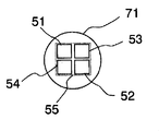
この点に関して、図2は、軸方向で、すなわちロッド7の光軸に沿って見たときの、図1に示すライトユニット2のロッド7の光入射面71の平面図を示す。図2に示す例では、ロッドは円形の断面を有する。したがってこの場合、ロッドは円柱状である。光伝播方向で見たときに2×2行列構成に配置される4つの発光ダイオード51、52、53、54が、光入射面71の下に、照明のために設けられる。
In this regard, FIG. 2 shows a plan view of the
図2を参照して分かるように、各発光面の外縁の仮想輪郭の領域、すなわち、エンベロープ55の領域は、平面図で見たとき、光入射面71よりも小さい。これは、領域のサイズだけでなく、特に、光入射面71及びエンベロープ55の側方寸法にも当てはまる。したがって、エンベロープ55の対角線は、光入射面71の直径よりも短い。
As can be seen with reference to FIG. 2, the region of the virtual contour at the outer edge of each light emitting surface, that is, the region of the
発光ダイオード51、52、53、54はまた、光軸に沿った平面図で見たとき、光入射面71が半導体光源の発光面のエンベロープの領域を完全に覆うように配置される。
The
図3は、図1に示す例の変形形態を概略的に示す。この例では、光屈折全反射ロッド7の代わりに、コンデンサ光学系20が設けられる。この場合、発光ダイオード5からの光は、発光ダイオード5の上方に各々配置されるコンデンサレンズ21によって平行に集束して結像する。
FIG. 3 schematically shows a variation of the example shown in FIG. In this example, a condenser
生成された光線の平行ビームを光ガイドの入口側の端面91上に偏光して重ね合わせるプリズム22が設けられる。よく画定された平行光線ビームが小さな光源用に生成され得るため、特に、狭い領域又は実際は点状の発光ダイオードの場合、非常に良好な色混合は、このような構成によって実現される。
A
図4は、破断線の輪郭によって概略的に示されるコックピット30の照明装置1の例示的な実施形態を示す。コックピット30は、様々な照明表示素子及び制御素子を備える。図4に示す例では、コックピットは、特に、機器用のオン/オフスイッチ31と、燃料ゲージディスプレイ32と、セレクタノブ33と、危険警告灯を作動させるスイッチ34とを備える。例として、照明される表面は、各々シェーディングで示す。
FIG. 4 shows an exemplary embodiment of the
光ガイド9のファイバ束は、空間的に分離した複数の端部93、94、95、96に分割される。各端部93、94、95、96は、制御素子及び表示素子31、32、33、34のうちの1つに各々結合され、光を発光ダイオード5から各光出射面に導く。これらを、たとえば、ファイバ端部が埋め込まれる、成形される透明プラスチック部分として設計することができる。本発明の一実施形態によれば、より複雑な幾何学的形状の照明面を生成するために、光ガイドの端部を扇状に広げて、各ファイバ端部を照明面の幾何学的形状に応じて隣り合わせて配置してもよい。したがって、図4に示す例示的な実施形態では、表示素子及び制御素子に影で示す照明面はいずれも、単純な径方向において対称な形状を有していない。2つのスイッチ31及び34は、径方向において非対称な形状を有する、たとえばフレーム形の照明面、たとえば直線状の外周を有する照明面を有する。したがって、単一の光源がこのような照明面を均一に照明するのは困難である。
The fiber bundle of the
これに加えて、表示素子及び制御素子31、32、33、34の照明面は、ライトユニット及び光混合装置による中央照明のため、厳密に同じ色及び強度に対する一定性を有する。さらに、照明面の強度及び/又は色も、別個に適合することもできる。
In addition, the illumination surfaces of the display and control
このために、示す例では、LED5の電源を調整及び/又は制御する調整装置40が提供される。選択ノブ33はここで、たとえば、選択ノブ33が全ての照明面の色及び/又は強度を均一に調整することができるように、調整装置40を設定するために使用されている。したがって、LED5の少なくとも2つの強度が、色を修正するために、調整装置40によって互いに対して調整される。
For this purpose, in the example shown, an
光ガイド9の各端部は、照明面内に直接に導かれる必要はない。むしろ、たとえばより単純な配線のために、さらなる光素子、及び特にさらなる光ガイドに結合するように光ガイド9又は別個の端部の少なくとも1つに光結合装置を設けることも可能であり得る。図4に示す例では、光ガイド9の端部94に、光学ジャックコネクタ97が設けられている。ジャックコネクタ97は、さらなる光ガイド98に取り付けるのに使用され、当該光ガイド98は、最終的に燃料ゲージディスプレイ32の照明面に接続される。
Each end of the
上述したような構成に対応する方法で、車両の内部照明も生成することができる。この場合、特にシグナル照明、たとえば航空機の灯火式滑走路を意図することができる。 The interior lighting of the vehicle can also be generated in a manner corresponding to the configuration as described above. In this case, it is possible in particular to contemplate signal lighting, for example an aircraft runway.
図5は、図1に示すライトユニット2の別の変形形態を示す。この変形形態では、概ねプリズム状の、特に円柱状のロッド7の代わりに、円錐状のロッド7が使用される。ロッド7は、光入射面71が光出射面よりも小さくなるように適合される。平面図で見たとき、光ガイドに結合した光出射面72は、光入射面71を完全に覆う。
FIG. 5 shows another modification of the
発光ダイオード5が発光する、より大きな立体角の光が光出射面に送られるため、この形状は好ましい。光の伝播方向で光軸に沿って広がる形状のため開口数も増加するが、これは、当該形状が、壁73上の光線の入射角を増加させ、且つ壁に当たるが全反射しない光線の割合を減少させるためである。
This shape is preferable because light having a larger solid angle emitted from the light-emitting
本発明が上述の例示的な実施形態に限定されないことは、当業者には明白である。むしろ、例示的な実施形態を様々な方法で変更してもよく、当該例示的な実施形態の各特徴は互いに組み合わせてもよい。 It will be apparent to those skilled in the art that the present invention is not limited to the exemplary embodiments described above. Rather, the exemplary embodiment may be modified in various ways and the features of the exemplary embodiment may be combined with each other.
Claims (23)
異なる色を有する光を発光する少なくとも2つの半導体光源と、
該少なくとも2つの半導体光源からの該光が入射する端面を有する少なくとも1つの光ガイドと、
該光ガイドの入口側に配置されると共に光屈折透明素子を有する光混合装置と
を備え、
該光混合装置によって、該少なくとも2つの半導体光源からの該光の空間分布が混合されて、該少なくとも2つの半導体光源からの該光の色の重ね合わせを構成する光を生成し、
該光屈折透明素子は、側壁と、該少なくとも2つの半導体光源が発光する該光の光入射面を形成する端面と、光射出面を形成するさらなる端面と、を有し、
該少なくとも2つの半導体光源は、該光入射面の前方において隣り合って配置され、
該少なくとも1つの光ガイドは、該光ガイドに隣接するカバーの第1の端部でフレームに固定され、
該カバーは、該少なくとも2つの半導体光源に隣接する第2の端部を有し、該第2の端部は、該少なくとも2つの半導体光源の支持体が備え付けられているヒートシンクを固定し、
該光屈折透明素子は、光入射面が該少なくとも2つの半導体光源の前に所定の間隔を有して近接して位置するように、該フレーム内に配置され、
該光屈折透明素子の光出射面は、該少なくとも1つの光ガイドの該端面の前に配置される、
照明装置。 A lighting device,
At least two semiconductor light sources that emit light having different colors;
At least one light guide having an end face on which the light from the at least two semiconductor light sources is incident;
A light mixing device disposed on the entrance side of the light guide and having a photorefractive transparent element,
The light mixing device mixes the spatial distribution of the light from the at least two semiconductor light sources to produce light that constitutes a color superposition of the light from the at least two semiconductor light sources;
The photorefractive transparent element has a side wall, an end surface that forms a light incident surface of the light emitted from the at least two semiconductor light sources, and a further end surface that forms a light emission surface ,
The at least two semiconductor light sources are arranged adjacent to each other in front of the light incident surface ;
The at least one light guide is secured to the frame at a first end of a cover adjacent to the light guide;
The cover has a second end adjacent to the at least two semiconductor light sources, the second end fixing a heat sink provided with a support for the at least two semiconductor light sources;
The photorefractive transparent element is disposed in the frame such that a light incident surface is positioned in close proximity with a predetermined distance in front of the at least two semiconductor light sources,
A light exit surface of the photorefractive transparent element is disposed in front of the end surface of the at least one light guide;
Lighting device.
15に記載の照明装置。 The lighting device according to claim 15, wherein the fiber bundle is divided into a plurality of spatially separated ends.
Applications Claiming Priority (2)
| Application Number | Priority Date | Filing Date | Title |
|---|---|---|---|
| DE102007014871A DE102007014871B4 (en) | 2007-03-26 | 2007-03-26 | Lighting device, in particular for vehicles |
| DE102007014871.4 | 2007-03-26 |
Publications (3)
| Publication Number | Publication Date |
|---|---|
| JP2008243816A JP2008243816A (en) | 2008-10-09 |
| JP2008243816A5 JP2008243816A5 (en) | 2011-05-19 |
| JP5197085B2 true JP5197085B2 (en) | 2013-05-15 |
Family
ID=39719402
Family Applications (1)
| Application Number | Title | Priority Date | Filing Date |
|---|---|---|---|
| JP2008079550A Expired - Fee Related JP5197085B2 (en) | 2007-03-26 | 2008-03-26 | Especially lighting equipment for vehicles |
Country Status (4)
| Country | Link |
|---|---|
| US (1) | US7942562B2 (en) |
| EP (1) | EP2028510B1 (en) |
| JP (1) | JP5197085B2 (en) |
| DE (1) | DE102007014871B4 (en) |
Families Citing this family (22)
| Publication number | Priority date | Publication date | Assignee | Title |
|---|---|---|---|---|
| DE102005049579A1 (en) * | 2005-10-17 | 2007-04-19 | Patent-Treuhand-Gesellschaft für elektrische Glühlampen mbH | Light source that emits mixed-color light, and methods for controlling the color location of such a light source |
| US20110038173A1 (en) * | 2008-07-24 | 2011-02-17 | Pacific Insight Elctronics Corp. | Ambient lighting system |
| US8540409B2 (en) | 2010-05-27 | 2013-09-24 | Osram Opto Semiconductors Gmbh | Light guide and semiconductor luminaire |
| DE102010046342B4 (en) * | 2010-09-23 | 2012-11-08 | Audi Ag | Lighting device and vehicle with a lighting device |
| DE102011106595A1 (en) | 2011-06-16 | 2012-12-20 | Volkswagen Aktiengesellschaft | Lighting device arrangement i.e. rear light arrangement, for use in rear window of vehicle, has conductor enclosed by surface element and made of material, where melting point of material of conductor is higher than material of element |
| JP2013026162A (en) | 2011-07-25 | 2013-02-04 | Sharp Corp | Lighting system and headlight for vehicle |
| US8911130B2 (en) * | 2012-11-08 | 2014-12-16 | Sunoptic Technologies, Llc | Light engine for a fiberoptic illuminator |
| DE102013203823A1 (en) * | 2013-03-06 | 2014-09-11 | Bayerische Motoren Werke Aktiengesellschaft | Device for interior lighting of a motor vehicle |
| CN110553165A (en) * | 2013-09-17 | 2019-12-10 | 夸克星有限责任公司 | Light guide illumination device for direct-indirect illumination |
| DE102013112905A1 (en) * | 2013-11-22 | 2015-05-28 | Schott Ag | Optical element and lighting device with optical element |
| DE102013020552A1 (en) * | 2013-12-12 | 2015-06-18 | Daimler Ag | Fiber bundle arrangement and method for producing such a fiber bundle arrangement |
| US9500794B2 (en) * | 2013-12-23 | 2016-11-22 | Steven J. Richardson | Light intensifier |
| DE102015106049C5 (en) * | 2015-04-21 | 2022-11-03 | Schott Ag | Lighting device with side-emitting light-guiding fiber bundle |
| US10759339B2 (en) * | 2016-08-15 | 2020-09-01 | Ford Global Technologies, Llc | Vehicle light system |
| DE102018001029A1 (en) | 2018-02-08 | 2019-08-08 | MENTOR GmbH & Co. Präzisions-Bauteile KG | Lighting device with a side-emitting photoconductive fiber bundle |
| DE102018005048B4 (en) * | 2018-06-25 | 2023-11-30 | Mercedes-Benz Group AG | Vehicle, comprising at least one lighting arrangement |
| DE102019205726A1 (en) * | 2019-04-18 | 2020-05-07 | Audi Ag | Bracket for coupling light |
| DE102019209727B4 (en) * | 2019-07-03 | 2022-02-17 | Audi Ag | Modular system for forming at least one lighting arrangement, motor vehicle |
| TWI686634B (en) * | 2019-07-11 | 2020-03-01 | 友達光電股份有限公司 | Display device |
| JP2021086744A (en) | 2019-11-28 | 2021-06-03 | パナソニックIpマネジメント株式会社 | Light emitting device |
| DE202020101201U1 (en) * | 2020-03-04 | 2021-06-07 | Motherson Innovations Company Limited | Connection arrangement for connecting an LED module to a light guide which is arranged in an illuminated vehicle part of a vehicle, as well as an illuminated vehicle part and vehicle with such a connection arrangement |
| EP4382800A1 (en) * | 2022-12-06 | 2024-06-12 | HELLA GmbH & Co. KGaA | Illumination device for a vehicle and vehicle comprising such an illumination device |
Family Cites Families (25)
| Publication number | Priority date | Publication date | Assignee | Title |
|---|---|---|---|---|
| JPH02100043A (en) * | 1988-10-07 | 1990-04-12 | Fuji Photo Film Co Ltd | Side print head device |
| US5113244A (en) * | 1991-02-06 | 1992-05-12 | General Dynamics Corporation, Electronics Division | Fiber optic combiner/splitter |
| JP2579862Y2 (en) * | 1991-07-22 | 1998-09-03 | 矢崎総業株式会社 | Display device for vehicles |
| US5271079A (en) * | 1991-11-08 | 1993-12-14 | Finisar Corporation | Light mixing device with fiber optic output |
| DE4439547A1 (en) * | 1994-11-05 | 1996-05-09 | Hella Kg Hueck & Co | Internal lighting system for motor vehicle |
| US5613751A (en) * | 1995-06-27 | 1997-03-25 | Lumitex, Inc. | Light emitting panel assemblies |
| US7108414B2 (en) * | 1995-06-27 | 2006-09-19 | Solid State Opto Limited | Light emitting panel assemblies |
| US7027691B1 (en) * | 1999-10-05 | 2006-04-11 | Visteon Global Technologies, Inc. | Light coupling and distribution system |
| US6270244B1 (en) * | 1999-11-16 | 2001-08-07 | Dn Labs Inc | Fiber optic illumination system having diffraction grating wavelength selector |
| US6272269B1 (en) * | 1999-11-16 | 2001-08-07 | Dn Labs Inc. | Optical fiber/waveguide illumination system |
| DE10031303A1 (en) * | 2000-06-27 | 2002-01-10 | Arnold & Richter Kg | Lighting device with light emitting diodes (LED), lighting method and method for image recording with such an LED lighting device |
| US6921920B2 (en) * | 2001-08-31 | 2005-07-26 | Smith & Nephew, Inc. | Solid-state light source |
| DE10256365A1 (en) * | 2001-12-04 | 2003-07-17 | Ccs Inc | Light radiation device for testing semiconductor chip, has lens mounted on optical fibers in one-to-one correspondence and closer to light transmission end of optical fibers |
| JP3927130B2 (en) * | 2002-02-25 | 2007-06-06 | 有限会社エリート貿易 | Optical fiber decoration device using LED light source and its decoration |
| AU2002951465A0 (en) * | 2002-09-18 | 2002-10-03 | Poly Optics Australia Pty Ltd | Light emitting device |
| US7217022B2 (en) * | 2004-08-31 | 2007-05-15 | Opto Technology, Inc. | Optic fiber LED light source |
| US7506998B2 (en) * | 2004-09-24 | 2009-03-24 | Koninklijke Philips Electronics, N.V. | Illumination system |
| US20060091411A1 (en) * | 2004-10-29 | 2006-05-04 | Ouderkirk Andrew J | High brightness LED package |
| CN101061345A (en) * | 2004-11-17 | 2007-10-24 | 皇家飞利浦电子股份有限公司 | Light source and illumination device comprising at least one light-emitting element |
| DE102006004996A1 (en) * | 2005-02-01 | 2006-08-24 | Schott Ag | Light mixer for use in e.g. medical area, has transparent body provided with admission area with surface, through which light enters into body and emitting area with surface, through which light escapes from body and overlays optical path |
| JP2006276335A (en) * | 2005-03-29 | 2006-10-12 | Fuji Photo Film Co Ltd | Plastic optical fiber |
| JP2006317844A (en) * | 2005-05-16 | 2006-11-24 | Three M Innovative Properties Co | Side emission optical fiber and light emitting apparatus |
| JP4909546B2 (en) * | 2005-08-12 | 2012-04-04 | 株式会社リコー | Illumination device, light modulation device, and projection display device |
| JP3121455U (en) * | 2005-12-08 | 2006-05-18 | 雅子 鎌田 | Relaxing lighting module with 3 primary color light emitting diodes |
| US20070160334A1 (en) * | 2006-01-10 | 2007-07-12 | Cobb Weston T | End-emitting fiber optic indicia for motor vehicles |
-
2007
- 2007-03-26 DE DE102007014871A patent/DE102007014871B4/en active Active
-
2008
- 2008-03-25 US US12/055,072 patent/US7942562B2/en active Active
- 2008-03-26 JP JP2008079550A patent/JP5197085B2/en not_active Expired - Fee Related
- 2008-03-26 EP EP08005609.6A patent/EP2028510B1/en active Active
Also Published As
| Publication number | Publication date |
|---|---|
| DE102007014871A1 (en) | 2008-10-02 |
| EP2028510A3 (en) | 2010-01-06 |
| JP2008243816A (en) | 2008-10-09 |
| DE102007014871B4 (en) | 2012-09-27 |
| EP2028510A2 (en) | 2009-02-25 |
| US7942562B2 (en) | 2011-05-17 |
| US20080239748A1 (en) | 2008-10-02 |
| EP2028510B1 (en) | 2013-05-08 |
Similar Documents
| Publication | Publication Date | Title |
|---|---|---|
| JP5197085B2 (en) | Especially lighting equipment for vehicles | |
| US8764257B2 (en) | Optical device, in particular for a motor vehicle | |
| JP5658752B2 (en) | Freeform light module | |
| US8125709B2 (en) | Illumination device, in particular for microscopes | |
| JP4750389B2 (en) | Light-emitting diode illuminating device for optical observation device such as stereo microscope or stereo surgical microscope | |
| KR101810235B1 (en) | Light emitting device and luminaire | |
| JP2008243816A5 (en) | ||
| US9268078B2 (en) | Color-mixing convergent optical system | |
| CN101668661A (en) | Lighting assembly | |
| MXPA04008487A (en) | Single light-emitting diode vehicle lamp. | |
| CN102853374B (en) | LED (Light-Emitting Diode) stage lamp lens assembly and LED stage lamp | |
| CN101326401A (en) | Optical device for creating an illumination window | |
| US10139072B2 (en) | Lighting unit for a vehicle headlamp | |
| US8534893B2 (en) | Flat panel light source for a transillumination device of a microscope | |
| EP3366990B1 (en) | Led lamp | |
| JP2013535790A (en) | Ring light illuminator, beam shaper, and illumination method | |
| ITPR20100021A1 (en) | LUMINOUS LED PROJECTOR WITH UNIQUE REFLECTION BEAM | |
| JP6067576B2 (en) | Warning lights and dashboard | |
| KR20220037519A (en) | Lighting device for automobile headlamps | |
| CA2672966C (en) | Illumination device for an aircraft | |
| US20060290647A1 (en) | Optical waveguided dashboard display | |
| JP6963658B2 (en) | Lamp, light emitting module and its combination lens | |
| JP2008543100A (en) | Light emitting device | |
| CN107636384B (en) | Signal generating device for a command and/or signal instrument | |
| CN110360482B (en) | Optical system and searchlight with diffuser and honeycomb concentrator |
Legal Events
| Date | Code | Title | Description |
|---|---|---|---|
| A521 | Written amendment |
Free format text: JAPANESE INTERMEDIATE CODE: A523 Effective date: 20110324 |
|
| A621 | Written request for application examination |
Free format text: JAPANESE INTERMEDIATE CODE: A621 Effective date: 20110324 |
|
| A977 | Report on retrieval |
Free format text: JAPANESE INTERMEDIATE CODE: A971007 Effective date: 20120824 |
|
| A131 | Notification of reasons for refusal |
Free format text: JAPANESE INTERMEDIATE CODE: A131 Effective date: 20120904 |
|
| A521 | Written amendment |
Free format text: JAPANESE INTERMEDIATE CODE: A523 Effective date: 20121204 |
|
| TRDD | Decision of grant or rejection written | ||
| A01 | Written decision to grant a patent or to grant a registration (utility model) |
Free format text: JAPANESE INTERMEDIATE CODE: A01 Effective date: 20130108 |
|
| A61 | First payment of annual fees (during grant procedure) |
Free format text: JAPANESE INTERMEDIATE CODE: A61 Effective date: 20130205 |
|
| FPAY | Renewal fee payment (event date is renewal date of database) |
Free format text: PAYMENT UNTIL: 20160215 Year of fee payment: 3 |
|
| R150 | Certificate of patent or registration of utility model |
Free format text: JAPANESE INTERMEDIATE CODE: R150 Ref document number: 5197085 Country of ref document: JP Free format text: JAPANESE INTERMEDIATE CODE: R150 |
|
| R250 | Receipt of annual fees |
Free format text: JAPANESE INTERMEDIATE CODE: R250 |
|
| R250 | Receipt of annual fees |
Free format text: JAPANESE INTERMEDIATE CODE: R250 |
|
| R250 | Receipt of annual fees |
Free format text: JAPANESE INTERMEDIATE CODE: R250 |
|
| R250 | Receipt of annual fees |
Free format text: JAPANESE INTERMEDIATE CODE: R250 |
|
| R250 | Receipt of annual fees |
Free format text: JAPANESE INTERMEDIATE CODE: R250 |
|
| LAPS | Cancellation because of no payment of annual fees |