JP5191183B2 - Ultrasonic diagnostic equipment - Google Patents
Ultrasonic diagnostic equipment Download PDFInfo
- Publication number
- JP5191183B2 JP5191183B2 JP2007200105A JP2007200105A JP5191183B2 JP 5191183 B2 JP5191183 B2 JP 5191183B2 JP 2007200105 A JP2007200105 A JP 2007200105A JP 2007200105 A JP2007200105 A JP 2007200105A JP 5191183 B2 JP5191183 B2 JP 5191183B2
- Authority
- JP
- Japan
- Prior art keywords
- ultrasonic
- image
- subject
- distance
- interest
- Prior art date
- Legal status (The legal status is an assumption and is not a legal conclusion. Google has not performed a legal analysis and makes no representation as to the accuracy of the status listed.)
- Expired - Fee Related
Links
Images


Landscapes
- Ultra Sonic Daignosis Equipment (AREA)
Description
本発明は、超音波診断装置に係り、特に、被検体の生体組織の音速、弾性率、及び減衰定数などの被検体の生体組織の音響特性に関する情報を提供する超音波診断装置に関する。 The present invention relates to an ultrasonic diagnostic apparatus, and more particularly, to an ultrasonic diagnostic apparatus that provides information related to acoustic characteristics of a biological tissue of a subject such as sound speed, elastic modulus, and attenuation constant of the biological tissue of the subject.
従来の超音波診断装置は、非特許文献1(P.110)などに記載されているように、生体の平均音速を被検体の組織の音速として仮定して用いて、例えばBモード像などの超音波断層像(以下、適宜US像という。)を構成していた。 As described in Non-Patent Document 1 (P.110) and the like, a conventional ultrasonic diagnostic apparatus uses an average sound speed of a living body as a sound speed of a tissue of a subject and uses, for example, a B-mode image or the like. An ultrasonic tomographic image (hereinafter referred to as a US image as appropriate) was constructed.
すなわち、US像を構成するに際して、超音波の距離方向(以下、適宜超音波送信方向、或いは縦波の伝播方向という。)の距離換算は、仮定した音速の大きさと受信信号の到達時間とに基づいて、その受信波形を生成した反射体の深度を推定することによって行われていた。 That is, when constructing a US image, the distance conversion in the ultrasonic distance direction (hereinafter referred to as the ultrasonic transmission direction or the longitudinal wave propagation direction) is converted into the assumed sound velocity and the arrival time of the received signal. Based on this, the depth of the reflector that generated the received waveform is estimated.
すると、仮定された音速と被検体の実際の音速との間のずれが大きくなると、計測した関心部位が実際の大きさとかけ離れた大きさとして画像化されたり、設定音速によって決まるフォーカスにずれが生じて方位方向(超音波送信方向に直交する方向)の分解能が低下したりするなど、様々な弊害が発生する。 Then, if the deviation between the assumed sound speed and the actual sound speed of the subject increases, the measured region of interest is imaged as a size that is far from the actual size, or the focus that is determined by the set sound speed is shifted. As a result, various adverse effects such as a decrease in resolution in the azimuth direction (direction orthogonal to the ultrasonic transmission direction) occur.
一方、非特許文献1(P.112)には、音波伝播に関する特性量で生体組織変化の定量化が可能であることが記載されている。つまり、例えばがんは悪性度が増すにつれて、肝硬変などは繊維化が進展するにつれて音速が増加すること、脂肪化を伴う病変肝臓は、音速、密度とも減少して弾性的性質を示す体積弾性率が小さく(軟らかく)なることなどが知られている。このことから、被検体の組織の例えば音速、弾性率(体積弾性率)などの音響特性に関する情報を検者に提供できれば診断に有用であると考えられる。 On the other hand, Non-Patent Document 1 (P.112) describes that a change in living tissue can be quantified with a characteristic amount related to sound wave propagation. In other words, for example, as the malignancy of cancer increases, the speed of sound increases as fibrosis progresses in cirrhosis, etc., and the volumetric modulus of the lesioned liver with fatification decreases in both sound speed and density and exhibits elastic properties. Is known to be small (soft). From this, it is considered useful for diagnosis if it is possible to provide the examiner with information on acoustic characteristics such as sound velocity and elastic modulus (volume elastic modulus) of the tissue of the subject.
特許文献1には、被検体の関心部位に対して異なる方向からの走査によって2枚の超音波断層像を撮像し、この2枚の超音波断層像の相互相関演算をすることにより、被検体の音速を算出することが記載されている。これは、仮定された音速に基づいて断層像を構成する超音波エコー法では知りえない正確な距離情報(例えば、関心部位の画像上の位置と実際の位置とのずれの距離)を、2枚の超音波断層像の相互相関演算を利用することによって推定し、これに基づいて音速を算出するものである。 In Patent Document 1, two ultrasonic tomographic images are captured by scanning from different directions with respect to a region of interest of the subject, and the subject is subjected to cross-correlation calculation between the two ultrasonic tomographic images. Is calculated. This is because accurate distance information (for example, the distance between the position of the region of interest on the image and the actual position) that cannot be known by the ultrasonic echo method for constructing the tomographic image based on the assumed sound speed is 2 It is estimated by using the cross-correlation calculation of the ultrasonic tomographic images, and the sound speed is calculated based on the estimation.
しかしながら、上述の特許文献1に記載された技術は、相互相関演算を用いるため、算出された被検体の音速の信頼性が損なわれる場合がある。 However, since the technique described in Patent Document 1 uses cross-correlation calculation, the reliability of the calculated sound velocity of the subject may be impaired.
すなわち、相互相関処理の対象となる超音波断層像に、何らかの原因によりノイズなどが混入した場合には、この影響により算出される相互相関係数の信頼性は低下し、その結果、算出される被検体の音速の信頼性が損なわれるおそれがある。 That is, when noise or the like is mixed into the ultrasonic tomographic image to be subjected to the cross-correlation process for some reason, the reliability of the cross-correlation coefficient calculated due to this influence decreases, and as a result The reliability of the sound speed of the subject may be impaired.
そこで、本発明は、X線CT装置、磁気共鳴撮像装置などの画像撮像装置により撮像されたリファレンス断層像を用いて正確な距離情報を得ることにより、検者に提供する被検体の組織の音響特性に関する情報の信頼性を向上することを課題とする。 Therefore, the present invention obtains accurate distance information using a reference tomographic image captured by an image imaging apparatus such as an X-ray CT apparatus or a magnetic resonance imaging apparatus, thereby providing the sound of the tissue of the subject to be provided to the examiner. It is an object to improve the reliability of information on characteristics.
上記課題を解決するため、本発明の超音波診断装置は、画像撮像装置により取得される被検体のリファレンス断層像を記憶する記憶手段と、被検体のリファレンス断層像と同一断層面の超音波断層像を撮像する超音波撮像手段と、リファレンス断層像及び超音波断層像の2組以上の対応する組織部位に基準点を設定する基準点設定手段と、リファレンス断層像の設定基準点を超音波送信方向に相当する方向の直線上に投影した投影点間の距離をリファレンス距離として算出するとともに、このリファレンス距離と超音波断層像の設定基準点を超音波送信方向の直線上に投影した投影点間の距離である超音波距離とに基づいて、被検体の組織の音響特性に関する物理量を演算して表示手段に表示する音響特性評価手段とを備えることを特徴とする。 In order to solve the above-described problems, an ultrasonic diagnostic apparatus of the present invention includes a storage unit that stores a reference tomographic image of a subject acquired by an image capturing device, and an ultrasonic tomography on the same tomographic plane as the reference tomographic image of the subject. Ultrasonic imaging means for picking up an image, reference point setting means for setting a reference point in two or more corresponding tissue parts of a reference tomographic image and an ultrasonic tomographic image, and ultrasonic transmission of a reference reference point for the reference tomographic image The distance between the projected points projected on the straight line in the direction corresponding to the direction is calculated as a reference distance, and the reference distance and the set reference point of the ultrasonic tomographic image are projected between the projected points projected on the straight line in the ultrasonic transmission direction. And an acoustic characteristic evaluation unit that calculates a physical quantity related to the acoustic characteristic of the tissue of the subject and displays it on the display unit based on the ultrasonic distance that is .
すなわち、リファレンス断層像及び超音波断層像は、被検体の同一断層面を撮像した断層画像であるため、両断層像には対応する組織部位が含まれている。両断層像の2組以上の対応する組織部位に基準点が設定されれば、各断層像において、設定基準点を超音波送信方向(超音波送信方向に相当する方向)の直線上に投影した投影点間の距離、つまりリファレンス距離と超音波距離が求められる。この超音波距離は、仮定した音速と投影点間の超音波の往復の伝播に伴う所要時間とに基づいて得られた仮定の距離であるところ、リファレンス距離は、この超音波距離に相当する距離を、例えばX線CT装置、磁気共鳴撮像装置などの画像撮像装置で撮像したほぼ正確な距離である。したがって、リファレンス距離と超音波距離とを用いれば、音響特性に関する物理量の1つである仮定していた被検体の生体組織の音速を正確な値として演算することができる。 That is, since the reference tomographic image and the ultrasonic tomographic image are tomographic images obtained by imaging the same tomographic plane of the subject, both of the tomographic images include corresponding tissue parts. If reference points are set in two or more sets of corresponding tissue parts of both tomographic images, the set reference points are projected on a straight line in the ultrasonic transmission direction (direction corresponding to the ultrasonic transmission direction) in each tomographic image. A distance between projection points, that is, a reference distance and an ultrasonic distance are obtained. The ultrasonic distance is an assumed distance obtained based on the assumed sound speed and the time required for the propagation of the ultrasonic wave between the projection points. The reference distance is a distance corresponding to the ultrasonic distance. Is an almost accurate distance imaged by an image imaging apparatus such as an X-ray CT apparatus or a magnetic resonance imaging apparatus. Therefore, if the reference distance and the ultrasonic distance are used, the sound speed of the living tissue of the subject that is assumed as one of the physical quantities related to the acoustic characteristics can be calculated as an accurate value.
具体的には、被検体の組織の音速は、リファレンス距離と超音波距離との比と、超音波断層像を撮像した際の超音波の設定音速(仮定していた音速)とに基づいて演算される。また、被検体の組織の音響特性に関する物理量として、演算された音速と被検体の組織の密度とに基づいて、被検体の組織の弾性率を演算することもできる。 Specifically, the sound speed of the tissue of the subject is calculated based on the ratio between the reference distance and the ultrasonic distance and the set sound speed (assumed sound speed) of the ultrasonic wave when the ultrasonic tomographic image is captured. Is done. Further, as a physical quantity related to the acoustic characteristics of the tissue of the subject, the elastic modulus of the tissue of the subject can be calculated based on the calculated sound speed and the density of the tissue of the subject.
ここで、リファレンス断層像と超音波断層像の撮像断層面を合わせるためには、例えば、画像撮像装置により取得される被検体の断層像のボリュームデータを被検体に予め設定された被検体座標系に対応付けて記憶手段に記憶するとともに、
超音波探触子の位置及び傾きを検出するセンサの検出値に基づいて、超音波断層像のスキャン面の座標を被検体座標系に対応付けて算出することなどにより実現できる。つまり、超音波断層像のスキャン面に対応した断層像データをボリュームデータから抽出してリファレンス断層像を構成することにより、両断層像の撮像断層面を一致させることができる。
Here, in order to match the imaging tomographic planes of the reference tomographic image and the ultrasonic tomographic image, for example, a subject coordinate system in which volume data of the tomographic image of the subject acquired by the image capturing apparatus is set in advance in the subject In association with the storage means,
This can be realized by, for example, calculating the coordinates of the scan plane of the ultrasonic tomographic image in association with the object coordinate system based on the detection values of the sensor that detects the position and inclination of the ultrasonic probe. That is, the tomographic image data corresponding to the scan plane of the ultrasonic tomographic image is extracted from the volume data to form the reference tomographic image, whereby the imaging tomographic planes of both tomographic images can be matched.
また、本発明の超音波診断装置において、音響特性評価手段を、リファレンス距離と超音波断層像の設定基準点における反射エコー信号の振幅比とに基づいて、被検体の組織の音響特性に関する物理量を演算して表示手段に表示する構成としてもよい。 Further, in the ultrasonic diagnostic apparatus of the present invention, the acoustic characteristic evaluation means calculates a physical quantity related to the acoustic characteristic of the tissue of the subject based on the reference distance and the amplitude ratio of the reflected echo signal at the setting reference point of the ultrasonic tomographic image. It is good also as a structure which calculates and displays on a display means.
この場合、音響特性に関する物理量は、リファレンス距離と超音波断層像の設定基準点における反射エコー信号の振幅比と超音波断層像を撮像した際の超音波の設定周波数とに基づいて演算される被検体の組織の超音波の減衰定数とすることができる。 In this case, the physical quantity related to the acoustic characteristics is calculated based on the reference distance, the amplitude ratio of the reflected echo signal at the set reference point of the ultrasonic tomographic image, and the set frequency of the ultrasonic wave when the ultrasonic tomographic image is captured. The attenuation constant of the ultrasonic wave of the specimen tissue can be used.
以上のように、本発明の超音波診断装置は、例えばX線CT装置、磁気共鳴撮像装置のような、被検体の断層像を正確な尺度で撮像できる画像撮像装置で撮像されたリファレンス断層像を用いることにより正確な距離情報を得ているので、従来技術のような相関演算処理が不要である。したがって、相関演算処理に伴う音速などの演算結果の信頼性の低下を抑制でき、検者に提供する被検体の組織の音響特性に関する情報の信頼性を向上することができる。 As described above, the ultrasonic diagnostic apparatus of the present invention is a reference tomographic image captured by an image capturing apparatus capable of capturing a tomographic image of a subject with an accurate scale, such as an X-ray CT apparatus and a magnetic resonance imaging apparatus. Since accurate distance information is obtained by using, correlation calculation processing as in the prior art is unnecessary. Therefore, it is possible to suppress a decrease in reliability of calculation results such as sound speed associated with the correlation calculation process, and it is possible to improve the reliability of information regarding the acoustic characteristics of the tissue of the subject provided to the examiner.
また、本発明の超音波診断装置の他の態様は、画像撮像装置により取得される被検体の関心部位を含むリファレンス3次元ボリュームデータを格納する記憶手段と、画像撮像装置により取得された関心部位と同一の関心部位を含む超音波3次元ボリュームデータを撮像する超音波撮像手段と、リファレンス3次元ボリュームデータ及び超音波3次元ボリュームデータのそれぞれについて関心部位の体積を算出するとともに、算出された関心部位の体積の比に基づいて被検体の音響特性に関する物理量を演算して表示手段に表示する音響特性評価手段と、を備えてなることを特徴とする。 In another aspect of the ultrasonic diagnostic apparatus of the present invention, a storage unit that stores reference three-dimensional volume data including a region of interest of a subject acquired by the image capturing device, and a region of interest acquired by the image capturing device. And calculating the volume of the region of interest for each of the reference three-dimensional volume data and the ultrasonic three-dimensional volume data. Acoustic characteristic evaluation means for calculating a physical quantity related to the acoustic characteristic of the subject based on the volume ratio of the part and displaying the physical quantity on the display means.
すなわち、それぞれの3次元ボリュームデータから算出されるそれぞれの関心部位の体積は、上述のリファレンス距離及び超音波距離を集合させたものであると言える。すると、方位方向の画像化のずれが無視できるレベルであれば、リファレンス距離と超音波距離との関係が、リファレンス3次元ボリュームデータから算出された体積と超音波3次元ボリュームデータから算出された体積との関係と同様となる。そのため、算出された関心部位の体積の比に基づいて被検体の音響特性に関する物理量を演算することができる。 That is, it can be said that the volume of each region of interest calculated from each three-dimensional volume data is a collection of the above-described reference distance and ultrasonic distance. Then, if the imaging deviation in the azimuth direction is negligible, the relationship between the reference distance and the ultrasonic distance is a volume calculated from the reference three-dimensional volume data and a volume calculated from the ultrasonic three-dimensional volume data. It is the same as the relationship. Therefore, a physical quantity related to the acoustic characteristics of the subject can be calculated based on the calculated volume ratio of the region of interest.
具体的には、関心部位の体積の比と超音波断層像を撮像した際の超音波の設定音速とに基づく被検体の組織の音速、及び音速と被検体の関心部位の組織の密度とに基づく弾性率などの音響特性に関する物理量を演算することができる。 Specifically, the sound velocity of the tissue of the subject based on the volume ratio of the region of interest and the set sound velocity of the ultrasonic wave when the ultrasonic tomographic image is captured, and the sound velocity and the density of the tissue of the region of interest of the subject. It is possible to calculate a physical quantity related to acoustic characteristics such as the elastic modulus based on it.
特に、この態様では、リファレンス断層像と超音波断層像とを同一断層面で撮像すること、各断層像に基準点を設定することなどが不要であるため、装置を簡略化することができ、また操作性を向上することができる。 In particular, in this aspect, since it is not necessary to capture the reference tomographic image and the ultrasonic tomographic image on the same tomographic plane, and to set a reference point for each tomographic image, the apparatus can be simplified. In addition, operability can be improved.
本発明によれば、X線CT装置、磁気共鳴撮像装置などの画像撮像装置により撮像されたリファレンス断層像を用いて正確な距離情報を得ることにより、検者に提供する被検体の組織の音響特性に関する情報の信頼性を向上することができる。 According to the present invention, accurate distance information is obtained using a reference tomographic image captured by an image capturing apparatus such as an X-ray CT apparatus or a magnetic resonance imaging apparatus, thereby providing an acoustic of the tissue of the subject to be provided to the examiner. The reliability of information regarding characteristics can be improved.
以下、本発明を適用してなる超音波診断装置の実施例を説明する。なお、以下の説明では、同一機能部品については同一符号を付して重複説明を省略する。 Embodiments of an ultrasonic diagnostic apparatus to which the present invention is applied will be described below. In the following description, the same functional parts are denoted by the same reference numerals, and redundant description is omitted.
図1は、本発明の超音波診断装置の第1実施例の基本構成を示すブロック図である。図1に示すように、超音波診断装置10は、被検体との間で超音波を送受する複数の振動子が配列された超音波探触子11(以下、適宜探触子という。)と、探触子11に駆動信号を供給する送信回路12と、探触子11から出力される反射エコー信号に対し増幅、アナログディジタル変換などの処理を施す受信回路14と、探触子11の複数の振動子を駆動する超音波パルスの送信タイミングを、送信遅延回路16を介して制御して、被検体内に設定される焦点に向けて超音波ビームを形成するとともに、反射エコー信号の受信タイミングを、受信遅延回路18を介して制御して、反射エコー信号の位相を整合させる送受信制御回路20などを有して構成されている。
FIG. 1 is a block diagram showing the basic configuration of the first embodiment of the ultrasonic diagnostic apparatus of the present invention. As shown in FIG. 1, an ultrasonic
また、受信遅延回路18から出力される反射エコー信号を加算する加算回路22と、加算回路22から出力される反射エコー信号に基づき超音波断層像を構成する超音波像構成部24と、構成された超音波断層像を記憶する画像メモリ26と、画像メモリ26から読み出される超音波断層像を表示する表示部28などを有して構成されている。
Further, an
探触子11には、位置センサ30が貼り付けられている。位置センサ30は、ベッドなどに取り付けられたソース32から発生する例えば磁気信号を検知する磁気センサを有して構成されている。位置センサ30により、ソース座標系Sにおける探触子11の3次元的な位置及び傾きが検出される。ソース座標系Sは、ソース32を原点Soとする3次元直交座標系であり、X軸を被検体が横たわるベッドの短手方向、Y軸をベッドの長手方向、Z軸を鉛直方向に合わせられている。なお、ソース座標系Sは、3次元直交座標系に限らず、探触子11の位置を特定できるものであればよい。また、位置センサ30は、磁場を利用するものに限らず、例えば光を利用したものでもよい。
A
また、被検体の関心部位を含む断層像を撮像するX線CT装置である画像撮像装置34から出力される3次元ボリュームデータ(以下、ボリュームデータという。)を被検体に予め設定された被検体座標系Pに対応付けるボリュームデータ作成部36と、ボリュームデータ作成部36から出力されるボリュームデータを記憶する記憶手段としてのボリュームデータ記憶部38と、ボリュームデータ記憶部38のボリュームデータから所定の断層像データを抽出してリファレンス断層像を構成し、構成したリファレンス断層像を画像メモリ26に出力する抽出手段であるリファレンス像構成部40などを有している。
In addition, a three-dimensional volume data (hereinafter referred to as volume data) output from an
被検体座標系Pについては、被検体の特定部位が原点Poとして予め設定されている。例えば、腹部の治療効果を判定するときは、剣状突起や肋骨を原点Poとして設定することができる。また、リファレンス像構成部40により抽出される所定の断層像データとは、走査中の探触子11の位置及び傾きを検出する位置センサ30の検出値に基づいて算出される超音波断層像のスキャン面に対応したデータである。
For the subject coordinate system P, a specific part of the subject is set in advance as the origin Po. For example, when determining the therapeutic effect of the abdomen, the xiphoid process and the ribs can be set as the origin Po. The predetermined tomographic image data extracted by the reference
なお、ボリュームデータ記憶部38に入力するボリュームデータについては、画像撮像装置34により被検体座標系の位置データに対応付けられたボリュームデータを取得し、取得したボリュームデータを、ネットワークを介して入力したり、或いは、取得したボリュームデータを光磁気ディスクなどの可般性記憶媒体を経由して入力したりしてもよい。
As for volume data to be input to the volume
また、超音波断層像を構成する各部、リファレンス断層像を構成する各部、及び被検体の生体組織の音速などの音響特性に関する物理量を演算する音響特性評価部50などを制御する制御部42が設けられている。制御部42は、被検体の特定部位を原点とする被検体座標系Pを設定する座標系設定手段44と、探触子11の位置センサ30の検出値に基づき、探触子11により撮像される超音波断層像のスキャン面の座標を被検体座標系Pに対応付けて算出するスキャン面算出手段46を有している。また、制御部42に操作卓48からの指令が入力されるようになっている。
Further, a
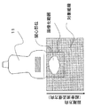
続いて、本実施例の特徴部である音響特性評価部50について説明する。本実施例では、超音波探触子としてリニア探触子を用いており、図2に示すように、対象組織の診断を行う。例えば、対象組織には図2に示すような関心部位があり、その関心部位を撮像しているとする。
Then, the acoustic
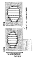
超音波撮像を実行すると、図3に示すように、関心部位を含むUS像が構成されて表示部28に表示されるとともに、超音波断層像のスキャン面の座標が検出され、ボリュームデータからUS像と同一断層面の断層像(以下、適宜CT像という。)が抽出されて表示部28に表示される。ただし、CT像は、表示部28に表示される必要はなく、例えば、X線CT装置の表示部に表示されていてもよい。
When ultrasonic imaging is executed, as shown in FIG. 3, a US image including a region of interest is constructed and displayed on the
なお、以下の説明では、超音波診断装置10の設定音速がCnow(例えば1538 (m/s))であり、その設定音速に基づいてUS像が距離換算、及び、スケーリングされているとする。また、このときの距離換算による単位長さ(単位)を、[m(Cnow)]と表記する。また、US像は、仮定した被検体の音速Cnowに基づくスケーリング[m(Cnow)]/pixelにより画像構成がなされている。
In the following description, it is assumed that the set sound speed of the ultrasonic
まず、検者によって、US像上に基準点1,2が入力される。また、リファレンス断層像となるCT像上の基準点1,2に対応する組織部位に基準点1´,2´が入力される。本実施例では、対応する組織部位を認識し易いように、関心部位の輪郭の下部の突起部を基準点2,2´とし、この基準点2,2´を通る超音波送信方向の直線と関心部位の輪郭の上部との交点を基準点1,1´としている。なお、CT像においては超音波送信方向というのは観念できないものであるが、両断層像の座標系は対応づけられているので、US像の超音波送信方向に相当する方向を、超音波送信方向とすることができる。 First, the reference points 1 and 2 are input on the US image by the examiner. In addition, reference points 1 ′ and 2 ′ are input to the tissue sites corresponding to the reference points 1 and 2 on the CT image serving as the reference tomographic image. In the present embodiment, in order to easily recognize the corresponding tissue site, the protrusions at the lower part of the contour of the site of interest are set as reference points 2 and 2 ′, and a straight line in the ultrasonic transmission direction passing through the reference points 2 and 2 ′ Intersections with the upper part of the contour of the region of interest are set as reference points 1 and 1 '. In the CT image, the ultrasonic transmission direction cannot be considered, but since the coordinate systems of both tomographic images are associated with each other, the direction corresponding to the ultrasonic transmission direction of the US image is set as the ultrasonic transmission direction. Can be direction.
続いて、US像において、基準点1,2間の距離(以下、基準点を結ぶラインを評価ラインという。)が関心部位の距離方向の超音波距離Dusとして計測される。つまり、US像上の関心部位の距離方向の長さは、Dus[m(Cnow)]となる。 Subsequently, in the US image, a distance between the reference points 1 and 2 (hereinafter, a line connecting the reference points is referred to as an evaluation line) is measured as an ultrasonic distance Dus in the distance direction of the region of interest. That is, the length in the distance direction of the region of interest on the US image is D us [m (C now )].
さらに、CT像においても同様に、基準点1´,2´間の距離が関心部位の距離方向のリファレンス距離Dctとして計測される。このリファレンス距離Dctは、正しい組織の大きさの値Dtrue [m]となる。つまり、CT像上の関心部位の距離方向のリファレンス距離は、正しい距離方向の距離なので、Dct=Dtrue[m]となる。 Further, in the CT image, similarly, the distance between the reference points 1 ′ and 2 ′ is measured as the reference distance Dct in the distance direction of the region of interest. The reference distance D ct is a correct tissue size value D true [m]. That is, since the reference distance in the distance direction of the region of interest on the CT image is the distance in the correct distance direction, D ct = D true [m].
ここで、US像上での関係は、基準点1と2との間の超音波の往復の伝播に伴う所要時間をΔtとすると、以下の関係が成り立つ。 Here, the relationship on the US image is as follows when the time required for the reciprocal propagation of the ultrasonic wave between the reference points 1 and 2 is Δt.
(式1)
2×Dus =Cnow×Δt
一方、関心部位の正しい音速をCtrueとすると、正しい関係は、以下のように表される。
(Formula 1)
2 × D us = C now × Δt
On the other hand, when the correct sound speed of the region of interest is C true , the correct relationship is expressed as follows.
(式2)
2×Dtrue = Ctrue×Δt
(式1)、(式2)より、正しい音速は、以下のようになる。
(Formula 2)
2 × D true = C true × Δt
From (Expression 1) and (Expression 2), the correct sound speed is as follows.
(式3)
Ctrue = (Dtrue/Dus)×Cnow
= (Dct /Dus)×Cnow
したがって、計測されたDctとDus、及び既知のCnowを用いて被検体の組織の正しい音速Ctrueが求められる。計測されたDctとDus、及び算出されたCtrueは、図3に示すように、表示部28に表示される。
(Formula 3)
C true = (D true / D us ) × C now
= ( Dct / Dus ) x Cnow
Therefore, the correct sound velocity C true of the tissue of the subject is obtained using the measured D ct and D us and the known C now . The measured D ct and D us and the calculated C true are displayed on the
このように、本実施例によれば、被検体の断層像を正確な尺度で撮像できるX線CT装置で撮像されたリファレンス断層像を用いることにより、US像上の仮定の距離(超音波距離Dus)に対応する箇所の正確な距離情報(リファレンス距離Dct)を得ているので、従来技術のような相関演算処理が不要である。したがって、相関演算処理に伴う音速などの演算結果の信頼性の低下を抑制でき、検者に提供する被検体の組織の音速の信頼性を向上することができる。 As described above, according to the present embodiment, the assumed distance (ultrasonic distance) on the US image is obtained by using the reference tomographic image captured by the X-ray CT apparatus capable of capturing the tomographic image of the subject with an accurate scale. Since accurate distance information (reference distance D ct ) at a location corresponding to D us ) is obtained, correlation calculation processing as in the prior art is unnecessary. Accordingly, it is possible to suppress a decrease in reliability of calculation results such as sound speed accompanying the correlation calculation processing, and it is possible to improve reliability of sound speed of the tissue of the subject provided to the examiner.
また、同一の組織断面をUS像とCT像で同期してリアルタイムに同一画面上に表示することができるので、被検体の組織音速評価を、超音波エコー検査中に容易に行うことができ操作性に優れている。 In addition, since the same tissue cross section can be displayed on the same screen in real time in synchronization with the US image and CT image, the tissue sound velocity evaluation of the subject can be easily performed during ultrasonic echo examination. Excellent in properties.
なお、本実施例では、表示部28にUS像とCT像が並べて表示されて、基準点1,2及び1´,2´を設定して正しい音速を演算しているが、これに限られない。例えば、表示部28にUS像のみが表示され、US像上に基準点1,2を入力するとともに、CT像での基準点1,2に対応する箇所の距離をX線CT装置から取得し、取得した距離を、操作卓48を介して超音波診断装置に入力して正しい音速を求めることもできる。
In this embodiment, the US image and the CT image are displayed side by side on the
また、US像は、仮定した被検体の音速Cnowに基づくスケーリング[m(Cnow)]/pixelにより画像構成がなされている。そこで、演算により正しい音速を求めた後、正しい距離を示すスケーリング[m(Ctrue)]/pixelに基づいてゲージを変換、又は更新して、US像上に正しい距離関係を表すゲージを表示するようになっていてもよい。 In addition, the US image has an image structure based on the assumed scaling [m (C now )] / pixel based on the sound velocity C now of the subject. Therefore, after obtaining the correct sound speed by calculation, the gauge is converted or updated based on the scaling [m (C true )] / pixel indicating the correct distance, and the gauge representing the correct distance relationship is displayed on the US image. It may be like this.
また、本実施例では、リファレンス画像として、X線CT装置により得られるCT画像を用いているが、比較対象となる診断画像は、CT像のみならず、MRI、マンモグラフィー、PET、レントゲン画像など、関心部位の大きさを正しく描出し、対比できる情報であれば何でもよい。 In this embodiment, a CT image obtained by an X-ray CT apparatus is used as a reference image. However, diagnostic images to be compared are not only CT images, but also MRI, mammography, PET, X-ray images, etc. Any information can be used as long as the size of the region of interest can be correctly drawn and compared.
本発明の超音波診断装置の第2実施例について説明する。本実施例は、第1実施例と異なる手法で、US像及びCT像の同一断層面を取得するものである。 A second embodiment of the ultrasonic diagnostic apparatus of the present invention will be described. In the present embodiment, the same tomographic plane of the US image and the CT image is acquired by a method different from the first embodiment.
つまり、本実施例は、図4に示すように、第1実施例の位置センサ30、ソース32、ボリュームデータ作成部36、リファレンス像構成部40、座標系設定手段44、スキャン面算出手段46などを用いない構成とするものであり、その他の構成、処理内容は実施例1と同様である。
That is, in this embodiment, as shown in FIG. 4, the
この場合、ボリュームデータ記憶部38に被検体の関心部位を含むCT像をリファレンス断層像として格納しておき、このCT像の関心部位の断面に相当する同一断層面を、探触子を移動させながら探してUS像を撮像するようにすることができる。また、逆に事前にUS像を撮像しておき、US像に含まれる関心部位の断面に相当する同一断面をCTのボリュームデータからCT像として取得し、対比するようにしてもよい。
In this case, a CT image including the region of interest of the subject is stored as a reference tomographic image in the volume
また、US像及びCT像の3次元ボリュームデータを取得していれば、検査中に両画像間の対比を行う必要はなく、検査後にオフラインで評価することも可能である。例えば、関心部位を含むCT像を3次元ボリュームデータとして取得してボリュームデータ記憶部38に格納するとともに、同一の関心部位を含むUS像を3次元ボリュームデータとして画像メモリ26に格納する。そして、両ボリュームデータの断層像をスライス方向に沿って表示部28に表示させながら、各画像において関心部位の例えば面積、距離方向の距離などが最大になる断面(最大割面)を探して、これを同一断層面とすることもできる。両断層面の決定がなされた後の処理は、上述と同様である。
Further, if the three-dimensional volume data of the US image and the CT image is acquired, it is not necessary to compare the two images during the inspection, and the evaluation can be performed offline after the inspection. For example, a CT image including a region of interest is acquired as three-dimensional volume data and stored in the volume
本発明の超音波診断装置の第3実施例について説明する。本実施例は、音響特性評価部の処理が第1実施例と異なるのみであるので、その他の部分の説明は省略する。 A third embodiment of the ultrasonic diagnostic apparatus of the present invention will be described. Since the present embodiment is different from the first embodiment only in the process of the acoustic characteristic evaluation unit, the description of other parts is omitted.
第1実施例では、関心部位を通る1ラインを評価ラインとして設定して音速を評価する例を説明したが、評価ラインを複数本に拡張することができる。つまり、例えば図5に示すように、基準点1〜4、及びこれらに対応する基準点1´〜4´を設定し、2本の評価ラインのそれぞれで実施例1と同様の処理を行い、それぞれのラインで評価した音速を表示部28に表示するようになっていてもよい。
In the first embodiment, an example in which one line passing through the region of interest is set as an evaluation line and the sound speed is evaluated has been described, but the evaluation line can be extended to a plurality of lines. That is, for example, as shown in FIG. 5, reference points 1 to 4 and reference points 1 ′ to 4 ′ corresponding to these are set, and the same processing as in Example 1 is performed on each of the two evaluation lines. The speed of sound evaluated for each line may be displayed on the
また、得られた複数の音速結果に対して、統計的な処理(平均値や中央値など)を施し、包括的に関心組織の音速を評価し、その結果を表示部28に表示するようになっていてもよい。
Further, statistical processing (average value, median value, etc.) is performed on the obtained sound speed results, comprehensively evaluating the sound speed of the tissue of interest, and displaying the results on the
本発明の超音波診断装置の第4実施例について説明する。本実施例は、音響特性評価部の処理が第1実施例と異なるのみであるので、その他の部分の説明は省略する。 A fourth embodiment of the ultrasonic diagnostic apparatus of the present invention will be described. Since the present embodiment is different from the first embodiment only in the process of the acoustic characteristic evaluation unit, the description of other parts is omitted.
第1実施例では、CT像及びUS像のそれぞれに対して、基準点1,2,1´,2´を入力する例を説明したが、本実施例では、図6に示すように、検者がUS像及びCT像の関心部位の輪郭を、超音波診断装置の操作卓48の例えばマウスやトラックボールなどの入力手段を介して入力するようになっている。
In the first embodiment, an example in which the reference points 1, 2, 1 ′, and 2 ′ are input to the CT image and the US image has been described. However, in this embodiment, as shown in FIG. A person inputs the contour of the region of interest in the US image and CT image via an input means such as a mouse or a trackball on the
すると、超音波の送信方向(距離方向)は所定の方向であるので、超音波送信方向の直線と入力した輪郭との交点が、自ずと基準点として決定される。基準点が設定された後は、各評価ラインのそれぞれについて実施例1と同様の処理がなされる。つまり、本実施例によれば、実施例3をより効率的に行うことができる。 Then, since the ultrasonic transmission direction (distance direction) is a predetermined direction, the intersection between the straight line of the ultrasonic transmission direction and the input contour is naturally determined as the reference point. After the reference point is set, the same processing as in the first embodiment is performed for each evaluation line. That is, according to the present embodiment, the third embodiment can be performed more efficiently.
また、輪郭の入力作業は、一般に境界検出処理や輪郭抽出処理といわれる画像認識処理によって自動で行われるようにすることも可能であり、それにしたがえば、検者によらず、音速の計測の一連の作業をすべて自動で行うことができる。 The contour input operation can be automatically performed by an image recognition process generally called a boundary detection process or a contour extraction process, so that the sound velocity measurement can be performed regardless of the examiner. A series of operations can be performed automatically.
本発明の超音波診断装置の第5実施例について説明する。本実施例の超音波診断装置の基本構成は第1実施例と同様であるので、異なる部分のみを説明する。 A fifth embodiment of the ultrasonic diagnostic apparatus of the present invention will be described. Since the basic configuration of the ultrasonic diagnostic apparatus of the present embodiment is the same as that of the first embodiment, only different portions will be described.
第1実施例は、CT像から得られるリファレンス距離とUS像から得られる超音波距離との対比に基づいて音速を演算する例であるが、本実施例は、CT像のボリュームデータから得られる関心部位の体積と、US像のボリュームデータから得られる体積との対比に基づいて音速を演算するものである。 The first embodiment is an example in which the sound velocity is calculated based on the comparison between the reference distance obtained from the CT image and the ultrasonic distance obtained from the US image, but this embodiment is obtained from the volume data of the CT image. The sound speed is calculated based on the comparison between the volume of the region of interest and the volume obtained from the volume data of the US image.
最近では超音波診断でも3次元ボリュームデータに基づいて3次元表示を行うことが一般的になってきており、これによればUS像による関心部位の体積をVus、CT像による関心部位の体積をVctとして求めることが可能である。
まず、X線CT装置により取得される被検体の関心部位を含む3次元ボリュームデータをリファレンスボリュームデータとしてボリュームデータ記憶部38に格納する。また、X線CT装置により撮像された関心部位と同一の関心部位を含む3次元ボリュームデータを超音波ボリュームデータとして撮像する。そして、音響特性評価部50の構成要素である体積算出部によりリファレンスボリュームデータ及び超音波ボリュームデータのそれぞれについて関心部位の体積を算出する。
Recently, it has become common to perform three-dimensional display based on three-dimensional volume data even in ultrasonic diagnosis. According to this, the volume of a region of interest based on a US image is represented by V us and the volume of a region of interest based on a CT image. Can be obtained as Vct .
First, the three-dimensional volume data including the region of interest of the subject acquired by the X-ray CT apparatus is stored in the volume
一定の方向にのみ超音波を送信する通常のスキャン方法では、その方向(距離方向)に沿った軸のみが、装置の設定音速に依存した距離換算になるので、求められた体積の情報を用いて、以下の式から音速を求めることができる。 In a normal scanning method that transmits ultrasonic waves only in a certain direction, only the axis along that direction (distance direction) is converted into a distance that depends on the set sound speed of the device. Thus, the speed of sound can be obtained from the following equation.
(式4)
Ctrue =(Vct/ Vus)×Cnow
それぞれの3次元ボリュームデータから算出されるそれぞれの関心部位の体積は、上述のリファレンス距離及び超音波距離を集合させたものであると言えるので、方位方向の画像化のずれが無視できるレベルであれば、リファレンス距離と超音波距離との関係が、リファレンスボリュームデータから算出された体積と超音波ボリュームデータから算出された体積との関係と同様となる。そのため、算出された関心部位の体積の比に基づいて音速を求めることができる。
(Formula 4)
C true = (V ct / V us ) × C now
Since the volume of each region of interest calculated from each three-dimensional volume data can be said to be a collection of the above-mentioned reference distance and ultrasonic distance, it should be at a level where the deviation in imaging in the azimuth direction can be ignored. For example, the relationship between the reference distance and the ultrasonic distance is the same as the relationship between the volume calculated from the reference volume data and the volume calculated from the ultrasonic volume data. Therefore, the sound speed can be obtained based on the calculated volume ratio of the region of interest.
このように3次元ボリュームで評価すれば、US像とCT像の画像の間で同一の組織断面を探索して選出する手間が省けるため、音速計測の効率を大幅に向上させることができる。また、各断層像に基準点を設定することなどが不要であるため、操作性を向上することができる。 If the evaluation is made with the three-dimensional volume in this way, the time for searching for and selecting the same tissue cross section between the images of the US image and the CT image can be saved, and the efficiency of sound velocity measurement can be greatly improved. Further, since it is not necessary to set a reference point for each tomographic image, operability can be improved.
本発明の超音波診断装置の第6実施例について説明する。本実施例は、音響特性評価部の処理が第1実施例と異なるのみであるので、その他の部分の説明は省略する。 A sixth embodiment of the ultrasonic diagnostic apparatus of the present invention will be described. Since the present embodiment is different from the first embodiment only in the process of the acoustic characteristic evaluation unit, the description of other parts is omitted.
実施例1は、評価ラインが超音波の送信方向に沿うように基準点を設定する例であるが、本実施例は、評価ラインが超音波の送信方向に沿わないように基準点を設定する例である。 The first embodiment is an example in which the reference point is set so that the evaluation line is along the ultrasonic transmission direction. However, in this embodiment, the reference point is set so that the evaluation line is not along the ultrasonic transmission direction. It is an example.
つまり、実施例1(及び実施例3,4など)では、超音波送信方向に沿った同一のライン上に2つの基準点を設定し、その2点を結ぶ評価ラインをUS像とCT像で対比するものであるが、評価ラインの設定は必ずしも送信方向だけに限る必要はない。
図7に示すように、US像で基準点1を設定し、その基準点と同一の組織点をCT像上に基準点1´として設定する。同様にして、基準点2,基準点2´をそれぞれ設定する。このとき、US像の距離方向をz軸、方位方向をx軸、CT像の距離方向をz´軸、方位方向をx´軸とすると、各基準点の座標は、基準点1:(x1,z1),基準点2:(x2,z2),基準点1´:(x1´,z1´),基準点2´:(x2´,z2´)となる。
That is, in Example 1 (and Examples 3 and 4, etc.), two reference points are set on the same line along the ultrasonic transmission direction, and an evaluation line connecting the two points is a US image and a CT image. For comparison, the setting of the evaluation line is not necessarily limited to the transmission direction.
As shown in FIG. 7, the reference point 1 is set in the US image, and the same tissue point as the reference point is set as the reference point 1 ′ on the CT image. Similarly, a reference point 2 and a reference point 2 ′ are set. At this time, assuming that the distance direction of the US image is the z-axis, the azimuth direction is the x-axis, the distance direction of the CT image is the z′-axis, and the azimuth direction is the x′-axis, the coordinates of each reference point are the reference point 1: (x1 , Z1), reference point 2: (x2, z2), reference point 1 ′: (x1 ′, z1 ′), reference point 2 ′: (x2 ′, z2 ′).
このとき、基準点1,基準点2は、図に示すように、特に超音波の送信方向の同一ライン上に設定される必要はなく、このように一般的に拡張した場合は、基準点間の距離(評価ラインの長さ)の送信方向(距離方向)成分を互いに対比すればよい。つまり、Dus,Dctは、以下のように求められる。 At this time, the reference point 1 and the reference point 2 do not need to be set on the same line in the ultrasonic transmission direction as shown in the figure. The transmission direction (distance direction) components of the distance (the length of the evaluation line) may be compared with each other. That is, D us and D ct are obtained as follows.
(式5)
Dus = │z1 − z2│
(式6)
Dct = │z1´− z2´│
このように、US像の設定基準点を超音波送信方向の直線上に投影した投影点間の距離が超音波距離Dusとして求められ、CT像の設定基準点を超音波送信方向に相当する方向の直線上に投影した投影点間の距離がリファレンス距離Dctとして求められる。Dus,Dctが求められた後の処理は、実施例1と同様である。
(Formula 5)
D us = │z1-z2│
(Formula 6)
D ct = │z1'- z2'│
In this way, the distance between the projection points obtained by projecting the setting reference point of the US image onto the straight line in the ultrasonic transmission direction is obtained as the ultrasonic distance Dus , and the setting reference point of the CT image corresponds to the ultrasonic transmission direction. A distance between projection points projected on a straight line in the direction is obtained as a reference distance Dct . The processing after obtaining D us and D ct is the same as in the first embodiment.
本実施例によれば、例えば関心部位の輪郭の突起部分のような、両断層像間の対応する組織部位を特定しやすい箇所に基準点を設けることができるので、基準点の設定作業が簡便となる。 According to the present embodiment, the reference point can be provided at a location where the corresponding tissue site between the two tomographic images can be easily identified, such as the protruding portion of the contour of the site of interest. It becomes.
ただし、図7では距離方向と評価ラインの角度θを説明の便宜上大きく取ったが、このような場合には注意が必要になる。つまり、図7の(A1)−(基準点1)間の距離と、(A2)−(B2)間の距離は、US像上では同じであるが、超音波が伝播する経路となる組織が異なり、その音速もその組織に依存するので、実際の組織では(A1)−(基準点1)間の距離と(A2)−(B2)間の距離は異なる距離を持つことになる。 However, in FIG. 7, the distance direction and the angle θ of the evaluation line are set large for convenience of explanation. However, in such a case, attention is required. That is, the distance between (A1)-(reference point 1) in FIG. 7 and the distance between (A2)-(B2) are the same on the US image, but the tissue that becomes the path through which the ultrasonic wave propagates. In contrast, since the sound velocity depends on the organization, the distance between (A1)-(reference point 1) and the distance between (A2)-(B2) have different distances in an actual organization.
したがって、上記の観点から、関心部位の境界(辺縁)部に基準点をとると同時に、(1)角度θが大きい場合、(2)Dusに比較して、(A2)−(B2)間((A1)−(基準点1)間)の距離が大きい場合、(3)関心組織と周囲組織の間で音速の違いが大きい場合などには、関心組織と周囲組織の配置関係によっては、関心組織の音速を求める際の誤差が大きくなることがあり、その点を十分に注意する必要がある。したがって、距離方向に沿った2つの基準点を用いて評価する方が高精度な音速評価には望ましいと考えられる。 Therefore, from the above viewpoint, the reference point is set at the boundary (edge) portion of the region of interest, and (1) when the angle θ is large, (2) (A2) − (B2) as compared with Dus When the distance between (A1)-(reference point 1) is large, (3) When the difference in sound speed between the tissue of interest and the surrounding tissue is large, depending on the arrangement relationship between the tissue of interest and the surrounding tissue The error in obtaining the sound speed of the tissue of interest may become large, and it is necessary to pay close attention to this point. Therefore, it is considered that evaluation using two reference points along the distance direction is desirable for highly accurate sound velocity evaluation.
なお、基準点は、関心部位の輪郭などの辺縁部に限らず、内部の点を選出してもよい。例えば、関心部位の内部にある石灰化の領域などは断層像上で目印となるので、両断層像に現れる同一の石灰化領域を目印としてUS像とCT像でそれぞれ基準点を設定することが可能である。 The reference point is not limited to the edge part such as the contour of the region of interest, and an internal point may be selected. For example, since the calcification region in the region of interest is a mark on the tomographic images, it is possible to set a reference point for each of the US image and CT image using the same calcification region appearing in both tomographic images as a mark. Is possible.
また、本実施例では、評価ラインを2次元断層面に拡張して設定する方法を示したが、さらに、US像及びCT像のボリュームデータを用いて3次元体積内に拡張して評価することも可能である。この場合も、基準点間の超音波送信方向の成分の距離同士を対比すればよい。 In the present embodiment, the method for setting the evaluation line by extending it to the two-dimensional tomographic plane is shown. However, the evaluation line is further expanded and evaluated within the three-dimensional volume by using the volume data of the US image and the CT image. Is also possible. In this case as well, the distances of the components in the ultrasonic transmission direction between the reference points may be compared.
本発明の超音波診断装置の第7実施例について説明する。本実施例は、使用する超音波探触子、或いは超音波走査方法が上述の各実施例と異なるのみであるので、その他の部分の説明は省略する。 A seventh embodiment of the ultrasonic diagnostic apparatus of the present invention will be described. In the present embodiment, since the ultrasonic probe or the ultrasonic scanning method used is different from the above-described embodiments, the description of other portions is omitted.
上述の各実施例では、リニア探触子を用いたリニア走査(リニアスキャン)を前提に説明した。この場合にはリニア探触子の超音波送受信面に垂直な方向に超音波が送信され、探触子から見た距離方向は、超音波の送信方向に一致する。
しかし、本発明は、このような条件に限らず、コンベックス探触子などでも同様に可能である。また、例えばリニア探触子による空間コンパウンド法や、セクター探触子によるセクター走査など、超音波の送信方向が探触子の超音波送受信面に垂直な方向でないような走査方法に従った場合でも、第1実施例などと同様の手法で、被検体の生体組織の音速を求めることができる。
つまり、同一の組織点となる基準点をUS像とCT像でそれぞれ設定するとともに、それらの基準点を結ぶ評価ラインの超音波送信方向(距離方向、伝播方向)の成分の大きさを両画像間で対比することにより、任意の超音波探触子と走査方法の組み合わせで本方法による音速の評価方法を適用することができる。
In each of the above-described embodiments, description has been made on the assumption of linear scanning using a linear probe (linear scanning). In this case, the ultrasonic wave is transmitted in a direction perpendicular to the ultrasonic wave transmitting / receiving surface of the linear probe, and the distance direction viewed from the probe coincides with the ultrasonic wave transmission direction.
However, the present invention is not limited to such conditions, and can be similarly applied to a convex probe or the like. Also, even when following a scanning method in which the ultrasonic transmission direction is not perpendicular to the ultrasonic transmission / reception surface of the probe, such as a spatial compound method using a linear probe or sector scanning using a sector probe. The sound speed of the living tissue of the subject can be obtained by the same method as in the first embodiment.
That is, the reference points to be the same tissue point are set in the US image and the CT image, and the size of the component in the ultrasonic transmission direction (distance direction and propagation direction) of the evaluation line connecting these reference points is set in both images. By contrasting, the method for evaluating sound speed according to the present method can be applied by a combination of an arbitrary ultrasonic probe and a scanning method.
本発明の超音波診断装置の第8実施例について説明する。本実施例は、上述の各実施例で求められた被検体の組織の音速に基づいて、US像の分解能を向上させるものであり、基本構成及び音速を求める処理は上述の各実施例と同様であるので説明を省略する。 An eighth embodiment of the ultrasonic diagnostic apparatus of the present invention will be described. In this embodiment, the resolution of the US image is improved based on the sound speed of the tissue of the subject obtained in each of the above-described embodiments, and the basic configuration and the process for obtaining the sound speed are the same as those in each of the above-described embodiments. Therefore, explanation is omitted.
超音波エコー法に基づいた画像化における方位分解能は、超音波の放射方向に対して直角な方向での分解能であり、超音波ビームの幅によって決定される。この方位分解能を高めるために送信、あるいは受信において超音波ビームを収束させる方法が採られており、アレイ振動子では配列方向のビーム収束は送受信信号の遅延時間制御によるいわゆる電子収束法が採られている。
例えば、M本の振動子を用い、超音波探触子の超音波送受信面から距離F0の点(フォーカス点)に超音波収束させるには中心の振動子の送受信信号ほど大きな遅延時間を与える。すると、i番目の振動子の信号に与える遅延時間τiは、以下の式で表される。
(式7)
τi = {(i−0.5−M/2)d}2/(2F0 Cnow)
ただし、dは振動子間隔、Cnowは現時刻における音速設定値である。また、セクター走査方式などの超音波ビームを形成する方法として、超音波探触子のi番目の振動子エレメントに、以下の式の遅延時間を与えることによりθ方向に送信ビームを偏向させることが一般的に行われている。
(式8)
τi = (i−1)psinθ/ Cnow
ここで、pは振動子エレメントの間隔、Cnowは現時刻における音速設定値である。受信した信号にも送信時と同じ遅延時間を与えた後加算することにより、θ方向の反射波のみを受信することができる。上記設定値の音速Cnowは、上述の通り、従来の超音波エコー法では、被検体の組織の仮定した音速を用いている。
したがって、この仮定した音速の値が実際に観測している関心組織の音速と異なると、距離換算に誤差が生じるだけでなく、上記(式7)、(式8)からもわかるように、遅延時間にも誤差が生じ、送信フォーカス、受信フォーカスともにずれを生じることになる。これにより、US像の空間分解能が劣化する結果となる。
The azimuth resolution in imaging based on the ultrasonic echo method is a resolution in a direction perpendicular to the radiation direction of the ultrasonic wave, and is determined by the width of the ultrasonic beam. In order to increase this azimuth resolution, a method of converging the ultrasonic beam in transmission or reception is adopted. In the array transducer, the beam convergence in the arrangement direction employs a so-called electronic convergence method by controlling the delay time of transmission / reception signals. Yes.
For example, when M transducers are used and the ultrasound is converged to a point (focus point) at a distance F 0 from the ultrasound transmission / reception surface of the ultrasound probe, a larger delay time is given to the transmission / reception signal of the center transducer. . Then, the delay time τi given to the signal of the i-th vibrator is expressed by the following equation.
(Formula 7)
τi = {(i−0.5−M / 2) d} 2 / (2F 0 C now )
Here, d is the transducer interval, and Cnow is the sound speed setting value at the current time. Further, as a method of forming an ultrasonic beam such as the sector scanning method, the transmission beam is deflected in the θ direction by giving a delay time of the following expression to the i-th transducer element of the ultrasonic probe. Generally done.
(Formula 8)
τi = (i-1) psinθ / C now
Here, p is the interval between the transducer elements, and Cnow is the sound speed setting value at the current time. Only the reflected wave in the θ direction can be received by adding the received signal after giving the same delay time as that at the time of transmission. As described above, the sound velocity Cnow of the set value uses the sound velocity assumed in the tissue of the subject in the conventional ultrasonic echo method.
Therefore, if the assumed sound speed value is different from the sound speed of the tissue of interest that is actually observed, not only an error occurs in the distance conversion, but also as shown from the above (Expression 7) and (Expression 8), An error also occurs in time, and the transmission focus and the reception focus are shifted. As a result, the spatial resolution of the US image is deteriorated.
そこで本実施例では、上述の各実施例によって求めた関心部位の正確な音速Ctrueの値を超音波診断装置の送信遅延回路16,受信遅延回路18にフィードバックし、探触子11の各振動子に与える遅延時間の精度を向上させ、US像の高分解能化を実現するものである。
Therefore, in this embodiment, the value of the accurate sound velocity C true of the region of interest obtained by the above embodiments is fed back to the
まず、上述の各実施例で説明した音響特性評価部50で正しい音速Ctrueを演算して求める。次に、求められた音速の値Ctrueが音響特性評価部50から送受信制御回路20に渡され、(式7)で設定された遅延時間は、Ctrueの値に応じた遅延時間の設定として、以下のように更新される。
First, a correct sound speed C true is calculated and obtained by the acoustic
(式9)
τi = {(i−0.5−M/2)d}2/(2F0Ctrue)
この実施例では、正しい音速が求められた時点で連動して、装置により自動実行されるように説明したが、検者が超音波診断装置の操作卓48を介してCtrueの値を入力し、それに応じて送受信制御回路20の音速設定(遅延設定)の値が更新されるようになっていてもよい。
(Formula 9)
τi = {(i−0.5−M / 2) d} 2 / (2F 0 C true )
In this embodiment, it has been described that it is automatically executed by the apparatus in conjunction with the correct sound speed, but the examiner inputs the value of C true via the
本発明の超音波診断装置の第9実施例について説明する。本実施例は、音響特性評価部の処理が第1実施例などと異なるのみであるので、その他の部分の説明は省略する。
上述の各実施例では、被検体の生体組織の音響特性に関する物理量として、被検体の組織における音速を求める例を説明したが、本実施例は、被検体の生体組織の音響特性に関する物理量として、被検体の組織の体積弾性率を求めるものである。
すなわち、対象組織の密度が一定値ρであると仮定すると、被検体の組織の体積弾性率Kは以下の式により求められる。
A ninth embodiment of the ultrasonic diagnostic apparatus of the present invention will be described. Since the present embodiment is different from the first embodiment only in the process of the acoustic characteristic evaluation unit, the description of other parts is omitted.
In each of the above-described embodiments, the example of obtaining the sound velocity in the tissue of the subject as the physical quantity related to the acoustic characteristics of the biological tissue of the subject has been described, but in this embodiment, as the physical quantity related to the acoustic characteristics of the biological tissue of the subject, The volume modulus of elasticity of the tissue of the subject is obtained.
That is, assuming that the density of the target tissue is a constant value ρ, the bulk modulus K of the tissue of the subject can be obtained by the following equation.
(式10)
K = (Ctrue)2×ρ
例えば、非特許文献(P.111)に記載されているように、正常のヒト肝臓では、密度が1.06g/cm3 程度であることが知られているので、関心部位が肝臓の場合には、この密度の値と、計測したCtrueの値を用いて体積弾性率が求められるようになっている。
(Formula 10)
K = (C true ) 2 × ρ
For example, as described in Non-Patent Document (P.111), it is known that the density of normal human liver is about 1.06 g / cm 3. The volume elastic modulus is obtained using the density value and the measured C true value.
また、超音波診断装置の操作卓48を介して、検者が上記組織の密度ρを自由に入力し、それに基づいて体積弾性率の値が算出され、表示されるようになっていてもよい。
Further, the examiner may freely input the tissue density ρ through the
本発明の超音波診断装置の第10実施例について説明する。本実施例は、音響特性評価部の処理が第1実施例と異なるのみであるので、その他の部分の説明は省略する。
上述の各実施例では、被検体の生体組織の音響特性に関する物理量として、被検体の組織における音速,或いは弾性率(体積弾性率)を求める例を説明したが、本実施例は、被検体の生体組織の音響特性に関する物理量として、被検体の組織の減衰定数を求めるものである。
超音波の音響特性における減衰は、(dB/cm/MHz)の単位で表現され、単位長さあたりの減衰量で表現される。しかし、超音波エコー法においては上述の通り、音速を仮定しているために正しい距離を求められず、したがって、超音波エコー法に基づいた減衰の評価は、その分精度が低下する。
A tenth embodiment of the ultrasonic diagnostic apparatus of the present invention will be described. Since the present embodiment is different from the first embodiment only in the process of the acoustic characteristic evaluation unit, the description of other parts is omitted.
In each of the above-described embodiments, the example in which the sound velocity or the elastic modulus (volume elastic modulus) in the tissue of the subject is obtained as the physical quantity related to the acoustic characteristics of the biological tissue of the subject has been described. The attenuation constant of the tissue of the subject is obtained as a physical quantity related to the acoustic characteristics of the living tissue.
The attenuation in the acoustic characteristics of the ultrasonic wave is expressed in units of (dB / cm / MHz), and is expressed in an attenuation amount per unit length. However, in the ultrasonic echo method, as described above, since the speed of sound is assumed, a correct distance cannot be obtained. Therefore, the accuracy of attenuation evaluation based on the ultrasonic echo method is reduced accordingly.
本実施例では、例えば図3に示すように、US像上に2点の基準点1、2を設定するとともにCT像に基準点1´,2´を設定することにより、上述の説明の通り、その基準点1,2間の距離をDtrue[cm]として正確に求めることができる。同時にその基準点1,2のそれぞれにおけるエコー信号の振幅の大きさをAmp(1),Amp(2)とすると、基準点1から基準点2までの間の経路におけるエコーの減衰量ATT(1−2)は、超音波の周波数をf0 [MHz]とすると、以下の式で求められる。 In the present embodiment, for example, as shown in FIG. 3, two reference points 1 and 2 are set on the US image and reference points 1 ′ and 2 ′ are set on the CT image as described above. The distance between the reference points 1 and 2 can be accurately obtained as D true [cm]. At the same time, assuming that the amplitude of the echo signal at each of the reference points 1 and 2 is Amp (1) and Amp (2), the echo attenuation amount ATT (1) in the path from the reference point 1 to the reference point 2 -2) is obtained by the following equation, where the frequency of the ultrasonic wave is f 0 [MHz].
(式11)
ATT(1−2)=20log10{Amp(1)/Amp(2)}/Dtrue/f0 [dB/cm/MHz]
なお、エコー信号の振幅の比 Amp(1)/Amp(2)の代わりに、振幅の2乗の比{Amp(1)}2/{Amp(2)}2 を用いてもよい。
上記の方法に従えば、正確に減衰の大きさを評価することができ、減衰に基づいた組織鑑別を行うことが可能となる。
(Formula 11)
ATT (1-2) = 20 log 10 {Amp (1) / Amp (2)} / D true / f 0 [dB / cm / MHz]
Instead of the amplitude ratio Amp (1) / Amp (2) of the echo signal, the ratio of the square of the amplitude {Amp (1)} 2 / {Amp (2)} 2 may be used.
According to the above method, the magnitude of attenuation can be accurately evaluated, and tissue discrimination based on the attenuation can be performed.
なお、非特許文献1(P.113)に記載されているように、吸収の周波数に対する依存を、以下の式で表し、このα0(dB/cm/MHz)とnをパラメータとした検討も行われており、組織の種類や病変によりα0だけでなくnも変化することも指摘されているが、病変との詳細な対応関係は未解明である。 In addition, as described in Non-Patent Document 1 (P.113), the dependence of absorption on the frequency is expressed by the following equation, and the examination using α 0 (dB / cm / MHz) and n as parameters is also possible. Although it has been pointed out that not only α 0 but also n varies depending on the type of tissue and lesion, the detailed correspondence with the lesion has not been elucidated.
(式12)
α = α0・fn
また、非特許文献1(P.4)に記載されているように、周波数に対する減衰定数の変化を求め、これを周波数依存減衰或いはFDA(frequency dependent attenuation)と呼ぶ。正常な生体軟部組織のFDAはほぼ周波数の1乗に比例(正比例)するといわれるが、このFDAを用いて生体診断を行おうとする研究も報告されている。
(Formula 12)
α = α 0 · f n
Further, as described in Non-Patent Document 1 (P.4), a change in an attenuation constant with respect to a frequency is obtained, and this is called frequency dependent attenuation or FDA (frequency dependent attenuation). It is said that the FDA of normal soft tissue of a living body is approximately proportional to the first power of the frequency (directly proportional). However, studies have been reported to perform biodiagnosis using this FDA.
本発明の超音波診断装置の第11実施例について説明する。本実施例は、上述の各実施例で、被検体の生体組織の音速、弾性率、減衰定数などを求めた後に、これらに基づく画像を生成して検者に提供するものであるので、前提となる処理内容などについては説明を省略する。 An eleventh embodiment of the ultrasonic diagnostic apparatus of the present invention will be described. Since the present embodiment, in each of the embodiments described above, obtains the sound velocity, elastic modulus, attenuation constant, etc. of the biological tissue of the subject, generates an image based on these and provides it to the examiner. A description of the processing contents and the like will be omitted.
例えば、実施例4で説明した関心部位の輪郭を入力する場合を例にすると、まず、図6に示すように、関心部位の輪郭内部のすべての評価ラインi(i=0,1,2,・・・,N )についてその経路を伝播する超音波の音速Ctrue(i)を求める。 For example, in the case where the contour of the region of interest described in the fourth embodiment is input as an example, first, as shown in FIG. 6, all the evaluation lines i (i = 0, 1, 2, .., N)) determine the sound velocity C true (i) of the ultrasonic wave propagating through the path.
次に、音響特性評価部50の音響特性画像生成部により、図8に示すように、求められた音速Ctrue(i)の大きさに応じて、例えば、カラーが割り当てられており、各評価ラインをそのカラーで色付けして音速画像として構築する。また、色相階調化するだけではなく、例えば輝度により階調化することもできる。
Next, as shown in FIG. 8, for example, a color is assigned by the acoustic characteristic image generation unit of the acoustic
同様に、実施例9で説明した体積弾性率の大きさや、実施例10で説明した減衰の大きさを音速の場合と同様の方法によって画像として構築することが可能である。 Similarly, the magnitude of the bulk modulus described in the ninth embodiment and the magnitude of attenuation described in the tenth embodiment can be constructed as an image by a method similar to that in the case of sound velocity.
このように音響特性を画像化することにより、例えば図8の音速画像ように、極度に音速が速い方向が容易に認識される。その方向には、悪性腫瘍などの組織学的に硬く変性した組織がある可能性があり、診断情報として効果的に寄与する。 By imaging the acoustic characteristics in this manner, a direction in which the speed of sound is extremely high can be easily recognized, for example, as in the sound speed image of FIG. In that direction, there may be a histologically hard and denatured tissue such as a malignant tumor, which effectively contributes as diagnostic information.
また、3次元画像として音速画像、超音波減衰画像などが構築されて表示されるようになっていてもよい。また、本実施例では、ひとつの関心部位についてのみ音速を評価し画像化することを示したが、乳腺部位のように複数の組織がひとつの計測断面に分布する場合には、それぞれの部位(脂肪、乳腺、筋肉など)について独立して音響特性を評価し、それぞれの音速(体積弾性率、減衰)画像として構築し、表示できるようになっている。 Moreover, a sound speed image, an ultrasonic attenuation image, etc. may be constructed and displayed as a three-dimensional image. Further, in the present embodiment, it has been shown that the sound velocity is evaluated and imaged only for one region of interest, but when a plurality of tissues are distributed in one measurement cross section such as a mammary gland region, each region ( The acoustic characteristics of fat, mammary gland, muscle, etc.) can be evaluated independently, and can be constructed and displayed as respective sound velocity (volume modulus, attenuation) images.
以上、本発明の超音波診断装置の各実施例について説明したが、本発明は上述の各実施例に限られるものではない。例えば、実施例2の基本構成、及び実施例9で説明した処理により被検体の組織の体積弾性率を求め、これに基づき実施例11で説明した弾性画像を生成して表示するなど、各実施例を適宜組み合わせて用いることができる。 As mentioned above, although each Example of the ultrasonic diagnosing device of this invention was described, this invention is not limited to the above-mentioned each Example. For example, the basic configuration of Example 2 and the processing described in Example 9 are used to obtain the volume modulus of elasticity of the tissue of the subject, and the elasticity image described in Example 11 is generated and displayed based on this. Examples can be used in appropriate combinations.
10 超音波診断装置
11 超音波探触子
12 送信回路
14 受信回路
16 送信遅延回路
18 受信遅延回路
20 送受信制御回路
26 画像メモリ
28 表示部
34 画像撮像装置
36 ボリュームデータ作成部
38 ボリュームデータ記憶部
40 リファレンス像構成部
42 制御部
48 操作卓
50 音響特性評価部
DESCRIPTION OF
Claims (6)
Priority Applications (1)
| Application Number | Priority Date | Filing Date | Title |
|---|---|---|---|
| JP2007200105A JP5191183B2 (en) | 2007-07-31 | 2007-07-31 | Ultrasonic diagnostic equipment |
Applications Claiming Priority (1)
| Application Number | Priority Date | Filing Date | Title |
|---|---|---|---|
| JP2007200105A JP5191183B2 (en) | 2007-07-31 | 2007-07-31 | Ultrasonic diagnostic equipment |
Publications (3)
| Publication Number | Publication Date |
|---|---|
| JP2009034262A JP2009034262A (en) | 2009-02-19 |
| JP2009034262A5 JP2009034262A5 (en) | 2010-09-16 |
| JP5191183B2 true JP5191183B2 (en) | 2013-04-24 |
Family
ID=40436759
Family Applications (1)
| Application Number | Title | Priority Date | Filing Date |
|---|---|---|---|
| JP2007200105A Expired - Fee Related JP5191183B2 (en) | 2007-07-31 | 2007-07-31 | Ultrasonic diagnostic equipment |
Country Status (1)
| Country | Link |
|---|---|
| JP (1) | JP5191183B2 (en) |
Families Citing this family (5)
| Publication number | Priority date | Publication date | Assignee | Title |
|---|---|---|---|---|
| JP5389722B2 (en) | 2009-09-30 | 2014-01-15 | 富士フイルム株式会社 | Ultrasonic diagnostic apparatus and method for operating the same |
| JP5535574B2 (en) * | 2009-10-23 | 2014-07-02 | ジーイー・メディカル・システムズ・グローバル・テクノロジー・カンパニー・エルエルシー | Ultrasonic diagnostic equipment |
| EP2494925A1 (en) | 2011-03-03 | 2012-09-05 | Koninklijke Philips Electronics N.V. | Calculating the speed of ultrasound in at least two tissue types |
| JP2014124220A (en) * | 2012-12-25 | 2014-07-07 | Fujifilm Corp | Ultrasound diagnostic apparatus, tissue elasticity measurement method, and program |
| US10893849B2 (en) * | 2017-02-28 | 2021-01-19 | Canon Medical Systems Corporation | Ultrasound image diagnosis apparatus, medical image processing apparatus, and computer program product |
Family Cites Families (6)
| Publication number | Priority date | Publication date | Assignee | Title |
|---|---|---|---|---|
| JP2575583B2 (en) * | 1993-03-16 | 1997-01-29 | アロカ株式会社 | Estimation method of coefficient value related to ultrasonic wave propagation characteristics in living tissue |
| JP3209880B2 (en) * | 1995-05-09 | 2001-09-17 | 学校法人桐蔭学園 | Ultrasonic probe and ultrasonic diagnostic apparatus having the same |
| JP3413095B2 (en) * | 1998-03-13 | 2003-06-03 | 松下電器産業株式会社 | Tomographic image processing method and apparatus |
| JP2000185036A (en) * | 1998-12-24 | 2000-07-04 | Toshiba Corp | Medical image display device |
| EP1182970B1 (en) * | 1999-12-15 | 2006-05-10 | Koninklijke Philips Electronics N.V. | Diagnostic imaging system with ultrasound probe |
| JP2006246974A (en) * | 2005-03-08 | 2006-09-21 | Hitachi Medical Corp | Ultrasonic diagnostic equipment with reference image display function |
-
2007
- 2007-07-31 JP JP2007200105A patent/JP5191183B2/en not_active Expired - Fee Related
Also Published As
| Publication number | Publication date |
|---|---|
| JP2009034262A (en) | 2009-02-19 |
Similar Documents
| Publication | Publication Date | Title |
|---|---|---|
| US11635514B2 (en) | Imaging methods and apparatuses for performing shear wave elastography imaging | |
| CN103251429B (en) | Ultrasonic imaging apparatus | |
| KR101182880B1 (en) | Ultrasound system and method for providing image indicator | |
| US10251627B2 (en) | Elastography measurement system and method | |
| JP5376877B2 (en) | Ultrasonic diagnostic apparatus and image display program | |
| JP6288996B2 (en) | Ultrasonic diagnostic apparatus and ultrasonic imaging program | |
| KR102607014B1 (en) | Ultrasound probe and manufacturing method for the same | |
| WO2007138751A1 (en) | Ultrasonograph, medical image processing device, and medical image processing program | |
| WO2012086152A1 (en) | Ultrasound image-generating apparatus and image-generating method | |
| CN106963419B (en) | Analysis device | |
| EP2253275A1 (en) | Ultrasonic diagnostic apparatus, ultrasonic image processing apparatus and ultrasonic image processing method | |
| JPWO2011093193A1 (en) | Ultrasonic diagnostic apparatus and measuring point tracking method thereof | |
| EP2402745B1 (en) | Ultrasound diagnosis apparatus, image processing apparatus and image processing method | |
| JP4468432B2 (en) | Ultrasonic diagnostic equipment | |
| JP2021045561A (en) | Motion adaptive visualization in medical 4d imaging | |
| JP5683860B2 (en) | Ultrasonic diagnostic apparatus, ultrasonic image processing apparatus, ultrasonic diagnostic apparatus control program, and ultrasonic image processing program | |
| JP5191183B2 (en) | Ultrasonic diagnostic equipment | |
| KR101027599B1 (en) | Ultrasound system and method providing acoustic radiation force impulse imaging with high frame rate | |
| JP2008073423A (en) | Ultrasonic diagnostic apparatus, diagnostic parameter measuring device, and diagnostic parameter measuring method | |
| JP4350214B2 (en) | Ultrasonic diagnostic equipment | |
| JP5823184B2 (en) | Ultrasonic diagnostic apparatus, medical image processing apparatus, and medical image processing program | |
| JP2002315754A (en) | Fine-diameter probe type ultrasonic diagnostic instrument | |
| JP2013099386A (en) | Ultrasonic diagnostic apparatus and medical image processing apparatus | |
| JP4001666B2 (en) | Ultrasonic diagnostic equipment | |
| US20110098567A1 (en) | Three dimensional pulsed wave spectrum ultrasonic diagnostic apparatus and three dimensional pulsed wave spectrum data generation method |
Legal Events
| Date | Code | Title | Description |
|---|---|---|---|
| A521 | Written amendment |
Free format text: JAPANESE INTERMEDIATE CODE: A523 Effective date: 20100729 |
|
| A621 | Written request for application examination |
Free format text: JAPANESE INTERMEDIATE CODE: A621 Effective date: 20100729 |
|
| A131 | Notification of reasons for refusal |
Free format text: JAPANESE INTERMEDIATE CODE: A131 Effective date: 20120313 |
|
| A977 | Report on retrieval |
Free format text: JAPANESE INTERMEDIATE CODE: A971007 Effective date: 20120314 |
|
| A521 | Written amendment |
Free format text: JAPANESE INTERMEDIATE CODE: A523 Effective date: 20120427 |
|
| TRDD | Decision of grant or rejection written | ||
| A01 | Written decision to grant a patent or to grant a registration (utility model) |
Free format text: JAPANESE INTERMEDIATE CODE: A01 Effective date: 20130108 |
|
| A61 | First payment of annual fees (during grant procedure) |
Free format text: JAPANESE INTERMEDIATE CODE: A61 Effective date: 20130129 |
|
| R150 | Certificate of patent or registration of utility model |
Free format text: JAPANESE INTERMEDIATE CODE: R150 |
|
| FPAY | Renewal fee payment (event date is renewal date of database) |
Free format text: PAYMENT UNTIL: 20160208 Year of fee payment: 3 |
|
| S111 | Request for change of ownership or part of ownership |
Free format text: JAPANESE INTERMEDIATE CODE: R313111 |
|
| S533 | Written request for registration of change of name |
Free format text: JAPANESE INTERMEDIATE CODE: R313533 |
|
| R350 | Written notification of registration of transfer |
Free format text: JAPANESE INTERMEDIATE CODE: R350 |
|
| LAPS | Cancellation because of no payment of annual fees |