JP5190439B2 - Secondary battery - Google Patents
Secondary battery Download PDFInfo
- Publication number
- JP5190439B2 JP5190439B2 JP2009279751A JP2009279751A JP5190439B2 JP 5190439 B2 JP5190439 B2 JP 5190439B2 JP 2009279751 A JP2009279751 A JP 2009279751A JP 2009279751 A JP2009279751 A JP 2009279751A JP 5190439 B2 JP5190439 B2 JP 5190439B2
- Authority
- JP
- Japan
- Prior art keywords
- cylindrical
- electrode
- bare cell
- circuit board
- protection circuit
- Prior art date
- Legal status (The legal status is an assumption and is not a legal conclusion. Google has not performed a legal analysis and makes no representation as to the accuracy of the status listed.)
- Active
Links
- 238000003466 welding Methods 0.000 claims description 16
- 238000007599 discharging Methods 0.000 claims description 5
- 230000008878 coupling Effects 0.000 description 26
- 238000010168 coupling process Methods 0.000 description 26
- 238000005859 coupling reaction Methods 0.000 description 26
- PXHVJJICTQNCMI-UHFFFAOYSA-N Nickel Chemical compound [Ni] PXHVJJICTQNCMI-UHFFFAOYSA-N 0.000 description 12
- 229910052759 nickel Inorganic materials 0.000 description 6
- 239000004020 conductor Substances 0.000 description 5
- 238000003780 insertion Methods 0.000 description 5
- 230000037431 insertion Effects 0.000 description 5
- 239000000463 material Substances 0.000 description 5
- 239000000853 adhesive Substances 0.000 description 4
- 230000001070 adhesive effect Effects 0.000 description 4
- 238000005452 bending Methods 0.000 description 3
- XAGFODPZIPBFFR-UHFFFAOYSA-N aluminium Chemical compound [Al] XAGFODPZIPBFFR-UHFFFAOYSA-N 0.000 description 2
- 229910052782 aluminium Inorganic materials 0.000 description 2
- 238000005520 cutting process Methods 0.000 description 2
- 239000011810 insulating material Substances 0.000 description 2
- 238000004519 manufacturing process Methods 0.000 description 2
- 238000000034 method Methods 0.000 description 2
- 229920000139 polyethylene terephthalate Polymers 0.000 description 2
- 239000005020 polyethylene terephthalate Substances 0.000 description 2
- XEEYBQQBJWHFJM-UHFFFAOYSA-N Iron Chemical compound [Fe] XEEYBQQBJWHFJM-UHFFFAOYSA-N 0.000 description 1
- HBBGRARXTFLTSG-UHFFFAOYSA-N Lithium ion Chemical compound [Li+] HBBGRARXTFLTSG-UHFFFAOYSA-N 0.000 description 1
- 230000002159 abnormal effect Effects 0.000 description 1
- 230000004308 accommodation Effects 0.000 description 1
- 239000000956 alloy Substances 0.000 description 1
- 229910045601 alloy Inorganic materials 0.000 description 1
- 230000000994 depressogenic effect Effects 0.000 description 1
- 239000003792 electrolyte Substances 0.000 description 1
- 238000009413 insulation Methods 0.000 description 1
- 229910001416 lithium ion Inorganic materials 0.000 description 1
- 239000007773 negative electrode material Substances 0.000 description 1
- -1 polyethylene terephthalate Polymers 0.000 description 1
- 239000007774 positive electrode material Substances 0.000 description 1
- 238000003825 pressing Methods 0.000 description 1
- 239000000758 substrate Substances 0.000 description 1
Images


Classifications
-
- H—ELECTRICITY
- H01—ELECTRIC ELEMENTS
- H01M—PROCESSES OR MEANS, e.g. BATTERIES, FOR THE DIRECT CONVERSION OF CHEMICAL ENERGY INTO ELECTRICAL ENERGY
- H01M50/00—Constructional details or processes of manufacture of the non-active parts of electrochemical cells other than fuel cells, e.g. hybrid cells
- H01M50/10—Primary casings; Jackets or wrappings
- H01M50/102—Primary casings; Jackets or wrappings characterised by their shape or physical structure
- H01M50/107—Primary casings; Jackets or wrappings characterised by their shape or physical structure having curved cross-section, e.g. round or elliptic
-
- H—ELECTRICITY
- H01—ELECTRIC ELEMENTS
- H01M—PROCESSES OR MEANS, e.g. BATTERIES, FOR THE DIRECT CONVERSION OF CHEMICAL ENERGY INTO ELECTRICAL ENERGY
- H01M50/00—Constructional details or processes of manufacture of the non-active parts of electrochemical cells other than fuel cells, e.g. hybrid cells
- H01M50/10—Primary casings; Jackets or wrappings
- H01M50/147—Lids or covers
-
- H—ELECTRICITY
- H01—ELECTRIC ELEMENTS
- H01M—PROCESSES OR MEANS, e.g. BATTERIES, FOR THE DIRECT CONVERSION OF CHEMICAL ENERGY INTO ELECTRICAL ENERGY
- H01M10/00—Secondary cells; Manufacture thereof
- H01M10/42—Methods or arrangements for servicing or maintenance of secondary cells or secondary half-cells
- H01M10/4207—Methods or arrangements for servicing or maintenance of secondary cells or secondary half-cells for several batteries or cells simultaneously or sequentially
-
- H—ELECTRICITY
- H01—ELECTRIC ELEMENTS
- H01M—PROCESSES OR MEANS, e.g. BATTERIES, FOR THE DIRECT CONVERSION OF CHEMICAL ENERGY INTO ELECTRICAL ENERGY
- H01M10/00—Secondary cells; Manufacture thereof
- H01M10/42—Methods or arrangements for servicing or maintenance of secondary cells or secondary half-cells
- H01M10/425—Structural combination with electronic components, e.g. electronic circuits integrated to the outside of the casing
-
- H—ELECTRICITY
- H01—ELECTRIC ELEMENTS
- H01M—PROCESSES OR MEANS, e.g. BATTERIES, FOR THE DIRECT CONVERSION OF CHEMICAL ENERGY INTO ELECTRICAL ENERGY
- H01M50/00—Constructional details or processes of manufacture of the non-active parts of electrochemical cells other than fuel cells, e.g. hybrid cells
- H01M50/20—Mountings; Secondary casings or frames; Racks, modules or packs; Suspension devices; Shock absorbers; Transport or carrying devices; Holders
- H01M50/204—Racks, modules or packs for multiple batteries or multiple cells
- H01M50/207—Racks, modules or packs for multiple batteries or multiple cells characterised by their shape
- H01M50/213—Racks, modules or packs for multiple batteries or multiple cells characterised by their shape adapted for cells having curved cross-section, e.g. round or elliptic
-
- H—ELECTRICITY
- H01—ELECTRIC ELEMENTS
- H01M—PROCESSES OR MEANS, e.g. BATTERIES, FOR THE DIRECT CONVERSION OF CHEMICAL ENERGY INTO ELECTRICAL ENERGY
- H01M50/00—Constructional details or processes of manufacture of the non-active parts of electrochemical cells other than fuel cells, e.g. hybrid cells
- H01M50/50—Current conducting connections for cells or batteries
- H01M50/528—Fixed electrical connections, i.e. not intended for disconnection
-
- H—ELECTRICITY
- H01—ELECTRIC ELEMENTS
- H01M—PROCESSES OR MEANS, e.g. BATTERIES, FOR THE DIRECT CONVERSION OF CHEMICAL ENERGY INTO ELECTRICAL ENERGY
- H01M50/00—Constructional details or processes of manufacture of the non-active parts of electrochemical cells other than fuel cells, e.g. hybrid cells
- H01M50/50—Current conducting connections for cells or batteries
- H01M50/572—Means for preventing undesired use or discharge
-
- Y—GENERAL TAGGING OF NEW TECHNOLOGICAL DEVELOPMENTS; GENERAL TAGGING OF CROSS-SECTIONAL TECHNOLOGIES SPANNING OVER SEVERAL SECTIONS OF THE IPC; TECHNICAL SUBJECTS COVERED BY FORMER USPC CROSS-REFERENCE ART COLLECTIONS [XRACs] AND DIGESTS
- Y02—TECHNOLOGIES OR APPLICATIONS FOR MITIGATION OR ADAPTATION AGAINST CLIMATE CHANGE
- Y02E—REDUCTION OF GREENHOUSE GAS [GHG] EMISSIONS, RELATED TO ENERGY GENERATION, TRANSMISSION OR DISTRIBUTION
- Y02E60/00—Enabling technologies; Technologies with a potential or indirect contribution to GHG emissions mitigation
- Y02E60/10—Energy storage using batteries
-
- Y—GENERAL TAGGING OF NEW TECHNOLOGICAL DEVELOPMENTS; GENERAL TAGGING OF CROSS-SECTIONAL TECHNOLOGIES SPANNING OVER SEVERAL SECTIONS OF THE IPC; TECHNICAL SUBJECTS COVERED BY FORMER USPC CROSS-REFERENCE ART COLLECTIONS [XRACs] AND DIGESTS
- Y02—TECHNOLOGIES OR APPLICATIONS FOR MITIGATION OR ADAPTATION AGAINST CLIMATE CHANGE
- Y02P—CLIMATE CHANGE MITIGATION TECHNOLOGIES IN THE PRODUCTION OR PROCESSING OF GOODS
- Y02P70/00—Climate change mitigation technologies in the production process for final industrial or consumer products
- Y02P70/50—Manufacturing or production processes characterised by the final manufactured product
Landscapes
- Chemical & Material Sciences (AREA)
- Chemical Kinetics & Catalysis (AREA)
- Electrochemistry (AREA)
- General Chemical & Material Sciences (AREA)
- Engineering & Computer Science (AREA)
- Manufacturing & Machinery (AREA)
- Microelectronics & Electronic Packaging (AREA)
- Battery Mounting, Suspending (AREA)
- Connection Of Batteries Or Terminals (AREA)
- Sealing Battery Cases Or Jackets (AREA)
Description
本発明は、二次電池(Secondary Battery)に関するものであって、特に円筒形ベアセルを備える二次電池に関するものである。 The present invention relates to a secondary battery, and more particularly, to a secondary battery including a cylindrical bare cell.
近年、電子、通信、コンピュータ産業の急速な発展に伴い携帯用電子機器の普及が増えている。携帯用電子機器の電源としては再充電が可能な二次電池が主に用いられている。 In recent years, with the rapid development of the electronic, communications, and computer industries, the spread of portable electronic devices has increased. As a power source for portable electronic devices, rechargeable secondary batteries are mainly used.
現在、パック形態の電池が二次電池として広く使用されている。パック形態の電池は、電気エネルギー源を提供するベアセルとベアセルの充放電を制御する保護回路モジュール(PCM:Protection Circuit Module)とが一つのユニットに統合された形態である。保護回路モジュールは各種回路素子が実装され、ベアセルに装着される回路基板を備える。 Currently, pack-type batteries are widely used as secondary batteries. A battery in a pack form is a form in which a bare cell that provides an electrical energy source and a protection circuit module (PCM: Protection Circuit Module) that controls charging and discharging of the bare cell are integrated into one unit. The protection circuit module includes a circuit board on which various circuit elements are mounted and attached to the bare cell.
従来、ベアセルの形状が円筒形である場合は、保護回路モジュールの回路基板がベアセルの曲面の側面に位置する。保護回路モジュールの回路基板がベアセルの曲面の側面に位置することから、外部機器に接続するための別途の接続端子部が必要であった。また、保護回路モジュールの回路基板と外部機器接続用端子部とがワイヤによって接続されるが、このワイヤは使用中に損傷し易いという問題があった。 Conventionally, when the shape of the bare cell is cylindrical, the circuit board of the protection circuit module is located on the side surface of the curved surface of the bare cell. Since the circuit board of the protection circuit module is located on the side surface of the curved surface of the bare cell, a separate connection terminal for connecting to an external device is required. Further, the circuit board of the protection circuit module and the external device connecting terminal portion are connected by a wire, but there is a problem that the wire is easily damaged during use.
本発明の目的は、部品点数を減らして製造コストを低減し、外部衝撃による損傷の恐れが少ない保護回路モジュールが結合された円筒形ベアセルを備える二次電池を提供することにある。 An object of the present invention is to provide a secondary battery including a cylindrical bare cell to which a protection circuit module is coupled that reduces the number of parts to reduce the manufacturing cost and is less likely to be damaged by an external impact.
前記目的を達成するために、本発明の一実施例によると、第1電極を形成する円筒形缶と、第2電極を形成し、前記円筒形缶に結合される電極キャップを備える円筒形ベアセルと、前記ベアセルの電極キャップと対向するように配置された回路基板を備える保護回路モジュールとを含み、前記保護回路モジュールは、前記回路基板を前記ベアセルの第1電極に電気的に接続させる第1電極タブと、前記回路基板を前記ベアセルの第2電極に電気的に接続させる第2電極タブとを備えることを特徴とする二次電池が提供される。 To achieve the above object, according to one embodiment of the present invention, a cylindrical can cell comprising a cylindrical can forming a first electrode and an electrode cap forming a second electrode and coupled to the cylindrical can. And a protection circuit module comprising a circuit board disposed to face the electrode cap of the bare cell, wherein the protection circuit module electrically connects the circuit board to the first electrode of the bare cell. A secondary battery comprising an electrode tab and a second electrode tab for electrically connecting the circuit board to a second electrode of the bare cell is provided.
前記円筒形ベアセルの円筒形缶は、底板と、前記底板から延びた側壁とを備え、前記第1電極タブは、例えば、前記円筒形ベアセルの円筒形缶の側壁に溶接によって接合連結される。 The cylindrical can of the cylindrical bare cell includes a bottom plate and a side wall extending from the bottom plate, and the first electrode tab is joined and connected to the side wall of the cylindrical can of the cylindrical bare cell by welding, for example.
前記第1電極タブは、前記保護回路モジュールの回路基板に溶着されるベース部と、前記円筒形ベアセルの円筒形缶の側壁上部を覆うように延びた延長部とを備えることができる。この時、前記第1電極タブの延長部は、互いに分離して延びた第1枝と第2枝を備えることができる。また、前記円筒形ベアセルの円筒形缶の側壁には、内側に凹入したビーディング(beading)部が設けられ、前記第1電極タブの延長部には、前記円筒形ベアセルのビーディング部に挿入されるように形成された係止部が設けられる。 The first electrode tab may include a base part that is welded to a circuit board of the protection circuit module, and an extension part that extends to cover an upper side wall of a cylindrical can of the cylindrical bare cell. In this case, the extension of the first electrode tab may include a first branch and a second branch extending separately from each other. In addition, a beading portion recessed inward is provided on a side wall of the cylindrical can of the cylindrical bare cell, and an extension portion of the first electrode tab is provided on the beading portion of the cylindrical bare cell. A locking portion formed to be inserted is provided.
前記第1電極タブは、前記保護回路モジュールの回路基板に溶着されるベース部と、前記ベース部から前記ベアセル側に延びた第1延長部と、前記第1延長部から折り曲げられて延び、前記ベアセルの円筒形缶の側壁上端に連結される連結部とを備えることができる。この時、前記第1電極タブは、前記連結部から延び、前記ベアセルの円筒形缶の側壁を覆う第2延長部をさらに備えることができる。また、前記回路基板には、前記第1電極タブの前記連結部が露出するように設けられた開放溝が形成されることもある。 The first electrode tab includes a base portion welded to a circuit board of the protection circuit module, a first extension portion extending from the base portion toward the bare cell, and a bent portion extending from the first extension portion. And a connecting portion connected to the upper end of the side wall of the cylindrical can of the bare cell. In this case, the first electrode tab may further include a second extension portion extending from the connection portion and covering a side wall of the cylindrical can of the bare cell. The circuit board may be formed with an open groove provided to expose the connecting portion of the first electrode tab.
前記保護回路モジュールの第1電極タブは例えば二つである。この時、二つの第1電極タブは、回路基板の中心部を基準に互いに反対側に位置できる。 The first electrode tab of the protection circuit module is, for example, two. At this time, the two first electrode tabs can be positioned on opposite sides of the center of the circuit board.
前記第2電極タブは、前記保護回路モジュールの回路基板に溶着されるベース部と、前記ベース部から折り曲げられて前記ベアセル側に延びた延長部と、前記延長部から折り曲げられて前記ベアセルの電極キャップと溶接によって接合連結される連結部とを備えることができる。この時、前記保護回路モジュールの回路基板には、前記第2電極タブの前記連結部に対応する位置に貫通孔を形成することができる。 The second electrode tab includes a base portion that is welded to a circuit board of the protection circuit module, an extension portion that is bent from the base portion and extends toward the bare cell, and an electrode of the bare cell that is bent from the extension portion. A cap and a connecting portion joined and connected by welding can be provided. At this time, a through hole may be formed in the circuit board of the protection circuit module at a position corresponding to the connecting portion of the second electrode tab.
前記保護回路モジュールの回路基板は、充放電のために設けられた外部端子をさらに備えることができる。 The circuit board of the protection circuit module may further include an external terminal provided for charging / discharging.
前記ベアセルと前記回路基板の間に位置する支持構造物を含むことができる。 A support structure may be included between the bare cell and the circuit board.
前記支持構造物は、前記電極キャップと対向する底板と、前記底板から前記回路基板の方の延びた支持壁を備えることができる。 The support structure may include a bottom plate facing the electrode cap, and a support wall extending from the bottom plate toward the circuit board.
前記支持壁の端部は、前記回路基板と接することができる。 An end portion of the support wall may be in contact with the circuit board.
前記支持構造物は、前記支持壁の端部に設けられた結合突起をさらに備え、前記回路基板には、前記結合突起が挿入される結合溝が形成されることができる。 The support structure may further include a connection protrusion provided at an end of the support wall, and a connection groove into which the connection protrusion is inserted may be formed in the circuit board.
前記ベアセルの電極キャップは突出部を備え、前記回路基板と前記突出部の間の距離は少なくとも0.5mmであることができる。 The electrode cap of the bare cell may include a protrusion, and a distance between the circuit board and the protrusion may be at least 0.5 mm.
前記電極キャップは、前記回路基板の方に突出した突出部を備え、前記支持構造物の底板には、前記突出部が位置する貫通孔が形成されることができる。 The electrode cap may include a protrusion that protrudes toward the circuit board, and a through hole in which the protrusion is located may be formed in a bottom plate of the support structure.
前記支持構造物の底板は、前記回路基板に対応する形状に形成されることができる。 The bottom plate of the support structure may be formed in a shape corresponding to the circuit board.
前記二次電池は、前記底板と前記電極キャップを結合する付着手段をさらに含むことができる。 The secondary battery may further include an attaching unit that couples the bottom plate and the electrode cap.
前記付着手段は両面テープであることができる。 The attaching means may be a double-sided tape.
前記回路基板は、前記支持構造物の底板と対向する第1面を備え、前記回路基板の第1面には、電気回路素子が実装されることができる。 The circuit board may include a first surface facing a bottom plate of the support structure, and an electric circuit element may be mounted on the first surface of the circuit board.
前記支持構造物の底板はリング形状を成すことができる。 The bottom plate of the support structure may have a ring shape.
前記支持構造物の底板は、中央部に位置する貫通孔を備え、前記底板は、前記貫通孔が外部に開放されたオープン形態からなることができる。 The bottom plate of the support structure may include a through hole located at a central portion, and the bottom plate may have an open configuration in which the through hole is open to the outside.
前記支持構造物は、絶縁材質からなることができる。 The support structure may be made of an insulating material.
前記支持構造物は、互いに分離された第1支持部材と第2支持部材を備えることができる。 The support structure may include a first support member and a second support member that are separated from each other.
前記各支持部材は、前記電極キャップと対向する底板と、前記底板から前記回路基板の方に延びた支持壁を備えることができる。 Each of the support members may include a bottom plate facing the electrode cap, and a support wall extending from the bottom plate toward the circuit board.
本発明の他の実施例によると、第1電極を形成する円筒形缶と、第2電極を形成し、前記円筒形缶に結合される電極キャップをそれぞれ備え、互いに並んで配置された第1円筒形ベアセルおよび第2円筒形ベアセルと、前記二つの円筒形ベアセルの各電極キャップと対向するように配置された回路基板を備える保護回路モジュールとを含み、前記保護回路モジュールは、前記回路基板を前記第1ベアセルの第1電極と前記第2ベアセルの第1電極のそれぞれに電気的に接続させる二つの第1電極タブと、前記回路基板を前記第1ベアセルの第2電極と前記第2ベアセルの第2電極のそれぞれに電気的に接続させる二つの第2電極タブとを備えることを特徴とする二次電池が提供される。 According to another embodiment of the present invention, a cylindrical can that forms the first electrode and an electrode cap that forms the second electrode and is coupled to the cylindrical can, the first being arranged side by side. A cylindrical bare cell and a second cylindrical bare cell; and a protection circuit module including a circuit board disposed to face each electrode cap of the two cylindrical bare cells, the protection circuit module including the circuit board. Two first electrode tabs electrically connected to each of the first electrode of the first bare cell and the first electrode of the second bare cell; the second electrode of the first bare cell; and the second bare cell; A secondary battery comprising two second electrode tabs electrically connected to each of the second electrodes is provided.
前記二次電池は、前記第1ベアセルの円筒形缶および前記第2ベアセルの円筒形缶のそれぞれが、底板と、前記底板から延びた側壁とを備え、前記第1ベアセルの底板と前記第2ベアセルの底板とを電気的に接続する電極接続タブをさらに含むことができる。 In the secondary battery, each of the cylindrical can of the first bare cell and the cylindrical can of the second bare cell includes a bottom plate and a side wall extending from the bottom plate, and the bottom plate of the first bare cell and the second can An electrode connection tab for electrically connecting the bottom plate of the bare cell may be further included.
前記二次電池は、前記二つの円筒形ベアセル間を支持するガイド部材をさらに含むことができる。 The secondary battery may further include a guide member that supports between the two cylindrical bare cells.
本発明のまた他の実施例によると、第1電極を形成する円筒形缶と、第2電極を形成し、前記円筒形缶に結合される電極キャップをそれぞれ備え、各ベアセルの電極キャップが互いに反対側を向く状態で並んで配置される第1円筒形ベアセルおよび第2円筒形ベアセルと、前記の二つの円筒形ベアセル中の第2円筒形ベアセルの電極キャップと対向するように配置された回路基板を備える保護回路モジュールと、前記第1円筒形ベアセルの電極キャップと前記第2円筒形ベアセルの第1電極を接続する電極接続タブとを含み、前記保護回路モジュールは、前記回路基板を前記第1ベアセルの第1電極に電気的に接続させる第1電極タブと、前記回路基板を前記第2ベアセルの第2電極に電気的に接続させる第2電極タブとを備えることを特徴とする二次電池が提供される。 According to another embodiment of the present invention, a cylindrical can that forms the first electrode and an electrode cap that forms the second electrode and is coupled to the cylindrical can, and the electrode caps of the bare cells are connected to each other. A first cylindrical bare cell and a second cylindrical bare cell arranged side by side facing each other, and a circuit arranged to face the electrode cap of the second cylindrical bare cell in the two cylindrical bare cells A protection circuit module including a substrate; an electrode cap of the first cylindrical bare cell; and an electrode connection tab that connects the first electrode of the second cylindrical bare cell. A first electrode tab electrically connected to the first electrode of one bare cell; and a second electrode tab electrically connected to the second electrode of the second bare cell. Secondary battery is provided.
前記保護回路モジュールは、前記回路基板を前記第2ベアセルの第1電極に電気的に接続させる補助タブをさらに備えることができる。 The protection circuit module may further include an auxiliary tab that electrically connects the circuit board to the first electrode of the second bare cell.
本発明の構成によると、上述した本発明の目的を全て達成することができる。具体的には、外部端子を備える保護回路モジュールの回路基板が円筒形ベアセルの一端部に位置するため、部品点数が減って製造コストが低減し、二次電池が外部衝撃によって損傷する恐れが減る。 According to the configuration of the present invention, all of the above-described objects of the present invention can be achieved. Specifically, since the circuit board of the protection circuit module including the external terminals is located at one end of the cylindrical bare cell, the number of components is reduced, the manufacturing cost is reduced, and the possibility that the secondary battery is damaged by an external impact is reduced. .
以下、添付の図面を参照しながら本発明に係る実施例を詳しく説明する。但し、本発明はこれらの実施例に限定されるものではない。 Hereinafter, embodiments of the present invention will be described in detail with reference to the accompanying drawings. However, the present invention is not limited to these examples.
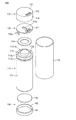
図1は本発明の一実施例に係る二次電池を示す斜視図であり、図2は図1に示す二次電池の分解斜視図であり、図3は図1において上部ケース(top case)、下部ケース(bottom case)およびラベル(label)をA−A線に沿って切断して内部を示す側面図である。図4は図2に示す円筒形ベアセルの断面図である。図5は図2に示す第1電極タブの斜視図である。図6は図3に示す第2電極タブの斜視図である。 1 is a perspective view showing a secondary battery according to an embodiment of the present invention, FIG. 2 is an exploded perspective view of the secondary battery shown in FIG. 1, and FIG. 3 is an upper case in FIG. FIG. 3 is a side view showing the inside by cutting a bottom case and a label along line AA. 4 is a cross-sectional view of the cylindrical bare cell shown in FIG. FIG. 5 is a perspective view of the first electrode tab shown in FIG. FIG. 6 is a perspective view of the second electrode tab shown in FIG.
図1〜図3に示すように、二次電池100は、ベアセル(bare cell)110と、保護回路モジュール120と、上部ケース(top case)145と、下部ケース(bottom case)160と、ラベル(label)170とを備える。
As shown in FIGS. 1 to 3, the
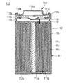
円筒形ベアセル110は、電気エネルギーを提供する構成を有し、図4には円筒形ベアセル110の縦断面図が示されている。図4に示すように、円筒形ベアセル110は電極組立体111、円筒形缶112、およびキャップ組立体113を備える。
The cylindrical
電極組立体111は、正極活物質がコーティングされた正極板111aと、負極活物質がコーティングされた負極板111bと、二つの極板111a、111bの間に位置し、二つの極板111a、111b間の短絡を防止すると共にリチウムイオンの移動だけを可能にするセパレータ111cとを備える。二つの極板111a、111bとセパレータ111cは、略円形に巻回されて渦巻状(jelly−roll)になる。また、二つの極板111a、111bに電極タブ111d、111eがそれぞれ溶着される。正極板111aに溶着される正極タブ111dは通常アルミニウム材質からなり、負極板111bに溶着される負極タブ111eは通常ニッケル材質からなるが、本発明は正極タブ111dと負極タブ111eの材質をこれに限定するのではない。電極組立体111の両端には絶縁のための第1絶縁プレート111fおよび第2絶縁プレート111gが結合される。
The
円筒形缶112はその内部空間に電極組立体111および電解液を収容する。円筒形缶112は通常アルミニウム(Al)や鉄(Fe)またはこれらの合金で形成される。円筒形缶112は、円形の底板112aと、底板112aの縁部から延びた側壁112bとを備える。円筒形缶112の上部は電極組立体の収容のために開放される。円筒形缶112の底板112aに電極組立体111の負極タブ111eが溶着される。それにより円筒形缶112は溶着された負極タブ111eと同極性を有し負極端子としての役割をする。円筒形缶112の側壁112bの上部には周り方向に沿ってリング状に延びたビーディング(beading)部112cが設けられる。ビーディング部112cは内側に凹入した溝の形状であって、下方には電極組立体111の移動を防止し、上方にはキャップ組立体113を支持する。円筒形缶112の側壁112bの上端は、内側に折り曲げられて圧接(cramping)部112dが形成される。圧接部112dはキャップ組立体113を上部の縁部を覆いキャップ組立体113を固定させる。
The cylindrical can 112 accommodates the
キャップ組立体113は、円筒形缶112の開放された上部を閉塞する。キャップ組立体113は電気伝導性安全ベント113a、印刷回路基板113b、陽性温度(PTC)素子113c、電極キャップ113d、および絶縁ガスケット113eを備える。安全ベント113aは、電池の過充電または異常発熱時に形態が反転し印刷回路基板113bのパターンを切断する。安全ベント113aに電極組立体111の正極タブ111dが電気的に接続される。印刷回路基板113bは、安全ベント113aの上部に電気的および機械的に接続される。印刷回路基板113bの回路パターンは安全ベント113aの反転時に切断される。PTC素子113cは、印刷回路基板113bの上部に電気的および機械的に接続される。PTC素子113cは、電池の過充電や内部短絡などによる異常発熱時に、その抵抗が非常に高くなり電池の内部回路を遮断する。電極キャップ113dは、PTC素子113cの上部に電気的および機械的に接続される。電極キャップ113dは、電池の実際電流を保護回路モジュール120に印加する機能をする。電極キャップ113dの中央部には接続が容易なように突出部1131dが設けられる。
The
絶縁ガスケット113eは、順に積層された安全ベント113a、印刷回路基板113b、PTC素子113c、および電極キャップ113dの外周部を覆いキャップ組立体113を一体化させる。絶縁ガスケット113eは、円筒形缶112のビーディング部112cと圧接部112dとの間に挟まれて固定される。絶縁ガスケット113eは、安全ベント113a、印刷回路基板113b、PTC素子113c、および電極キャップ113dを円筒形缶112と絶縁させる。
The insulating
前記ベアセル110についての説明で円筒形缶112は、負の極性を有し、端子キャップ113dは正の極性を有するものと説明したが、本発明はこれに制限されるものではない。電極組立体111の正極タブ111dおよび負極タブ111eの極性を互いに変えることによって、円筒形缶112が正の極性を、端子キャップ113dは負の極性を有することができる。
Although the
保護回路モジュール120は、ベアセル110に結合されてベアセル110の充放電を含む二次電池100の作動を制御する。図2および図3に示すように、保護回路モジュール120は、回路基板121と、二つの第1電極(負極)タブ130a、130bと、第2電極(正極)タブ140とを備える。
The
回路基板121は、配線パターンが印刷された印刷回路基板であって、通常円形であり、円筒形ベアセル110の上端に対応する大きさを有する。回路基板121の中央部には溶接棒が通過できる貫通孔121aが設けられる。回路基板121は、第1面121bと、第1面121bの反対面の第2面121cとを備える。第1面121bの半径方向の端部側において対称となる二箇所には第1電極タブ130a、130bがそれぞれ結合されている。第1面121bの中央部には第2電極タブ140が結合されている。第1面121bは、円筒形ベアセル110のキャップ組立体113の電極キャップ113dと一定距離で離隔されて互いに対向している。回路基板121の第1面121bには電気回路素子121dが実装されている。電気回路素子121dは、制御IC、充放電スイッチ、温度ヒューズなどの素子からなる。電気回路素子121dは、突出部1131dを除いた電極キャップ113dに貼着した絶縁テープ114により電極キャップ113dと絶縁される。絶縁テープ114の材質は、ポリエチレンテレフタレート(PET)であるが、本発明はこれに制限されるものではない。
The
回路基板121の第2面121cには、外部の負荷または充電器と電気的に接続される外部端子121eが設けられる。
The
図3に示すように、二つの第1電極タブ130a、130bのそれぞれは、回路基板121の半径方向の端部において互いに対称となる箇所に位置する。二つの第1電極タブ130a、130bは、ニッケルのような電気伝導性材質の板部材が折り曲げられて形成されたものであり、保護回路モジュール120の回路基板121をベアセル110の円筒形缶112に電気的に接続させる。
As shown in FIG. 3, each of the two
図5には、同一構成の二つの第1電極タブ130a、130b中の一つの第1電極タブ130aの構成が詳しく示されている。図5に示すように、第1電極タブ130aは、ベース部131aと、ベース部131aから折り曲げられて延びた延長部132aとを備える。
FIG. 5 shows in detail the configuration of one
ベース部131aは、通常四角形の扁平な板状であり、回路基板121の第1面121bに電気的に接続されるように溶着する。
The
延長部132aはベース部131aとほぼ直角をなす。延長部132aには、延長部132aの延長方向に沿って端部まで延びたスリット(slit)133aが設けられる。スリット133aによって互いに分離した第1枝134aと第2枝135aが形成される。第1枝134aは、延長方向に沿って順に位置する連結部1341aと、連結部1341aから折り曲げられた係止部1342aとを備える。連結部1341aは、ベアセル111の缶112のビーディング部112cと圧接部112dとの間で缶111の側壁112bと密着する。係止部1342aは、缶111のビーディング部112cに挿入され、第1電極用タブ130aが缶111に固定されるようにする。第2枝135aは、第1枝134aの構成と同様に、連結部1351aと係止部1352aとを備える。第1枝134aの連結部1341aと第2枝135aの連結部1351aのそれぞれは、ベアセル110の缶111の側壁112bに抵抗溶接されて接合連結される。この時、溶接機の二つの電極が、第1枝134aの連結部1341aと第2枝135aの連結部1351aとをそれぞれ加圧して抵抗溶接が行われる。二つの枝134a、135aがスリット133aにより分離しているので、二つの連結部1341a、1351aが曲面の円筒形缶112の側壁112bに良好に密着し、抵抗溶接がより一層効果的に行われる。
The
図3に示すように、第2電極タブ140は、保護回路モジュール120の回路基板121に形成された貫通孔121aに対応して位置する。第2電極用タブ140は、ニッケルのような電気伝導性材質の板部材が折り曲げられて形成されたものであり、保護回路モジュール120の回路基板121をキャップ組立体113の電極キャップ113dに電気的に接続させる。
As shown in FIG. 3, the
図6には、第2電極用タブ140の構成が詳しく示されている。図6に示すように、第2電極用タブ140は、第1および第2ベース部141、142と、第1および第2ベース部141、142からそれぞれ折り曲げられて延びた第1および第2延長部143、144と、二つの延長部143、144を連結する連結部145とを備える。
FIG. 6 shows the configuration of the
第1および第2ベース部141、142は、扁平な板状であり、回路基板121の第1面121bで貫通孔121aの両側にそれぞれ電気的に接続されるように溶着する。
The first and
第1延長部143は、第1ベース部141から折り曲げられてベアセル110の電極キャップ113d側に延びる。第2延長部144は、第2ベース部142から折り曲げられてベアセル110の電極キャップ113d側に延びる。
The
連結部145は、通常四角形の扁平な板状であり、第1延長部143の端部と第2延長部144の端部間を連結する。連結部145は、ベアセル110の電極キャップ113dに形成された突出部1131dに接続される。連結部145とベアセル110の電極キャップ113dに形成された突出部1131dは、回路基板121の貫通孔121aを通過して引き込んだ溶接棒によって抵抗溶接され接合連結される。
The connecting
上部ケース150は、保護回路モジュール120を内部空間に収容し、保護回路モジュール120を保護する。上部ケース150は、蓋板151と、蓋板151から下方に延びた側壁154とを備える。
The
蓋板151は、円形で、ベアセル110のキャップ組立体113とほぼ一致する形状を有する。蓋板151には貫通孔155が形成される。貫通孔155を通じて保護回路モジュール120の外部端子121eが外部に露出する。蓋板151の内面は、保護回路モジュール120の回路基板121の第2面121cと対向して接する。
The
側壁154の端部は、ベアセル110の円筒形缶112の側壁112bの上部を覆うように下方に延びる。図示してはいないが、側壁154の内面には円筒形缶112の側壁112bの上端に係止される係止突起が形成される。
The end of the
下部ケース160は、底板161と、底板161から上方に延びた側壁162とを備える。底板161は、ベアセル110の円筒形缶112の底板112aとほぼ同じ形状であり、両面テープのような接着部材163によりベアセル110の円筒形缶112の底板112aに結合される。側壁162はベアセル110の円筒形缶112の側壁112bの下部を覆う。
The
ラベル170は、ベアセル110の円筒形缶112の側壁112bを覆うように貼付される。ラベル170は上部ケース150の側壁154の一部と下部ケース160の側壁162上にも共に貼付される。
The
次は本発明の他の実施例に係る保護回路モジュールを詳しく説明する。 Next, a protection circuit module according to another embodiment of the present invention will be described in detail.
図7には、本発明の他の実施例に係る保護回路モジュールの斜視図が示されている。図7に示すように、保護回路モジュール220は、回路基板221と、二つの第1電極タブ230a、230bと、第2電極タブ140とを備える。
FIG. 7 is a perspective view of a protection circuit module according to another embodiment of the present invention. As shown in FIG. 7, the
回路基板221は、通常円形であり、中心部を基準に互いに対称となる位置に第1開放溝221aおよび第2開放溝221bが設けられる。二つの開放溝221a、221bは、回路基板221の端部から内側に凹入して形成されたものである。二つの開放溝221a、221bは、二つの第1電極タブ230a、230bをそれぞれ露出させてレーザ溶接ができるようする。
The
二つの第1電極タブ230a、230bは、ニッケルのような電気伝導性材質の板部材が折り曲げられて形成されたものであり、回路基板221をベアセル110の円筒形缶112に電気的に接続させる。図8には、同一構成の二つの第1電極タブ230a、230b中の一つの第1電極タブ230aの構成が詳しく示されている。図8に示すように、第1電極タブ230aは、ベース部231aと、ベース部231aから折り曲げられて延びた第1延長部232aと、第1延長部232aから折り曲げられて延びた連結部233aと、連結部233aから折り曲げられて延びた第2延長部234aとを備える。ベース部231aは一定の幅を有する円弧形の板状であり、回路基板221の第1開放溝221aに対応する位置に電気的に接続されて溶着される。第1延長部232aは、ベース部231aの半径方向の外側端部2311aから回路基板221の反対方向の下方に延びて形成される。連結部233aは、一定の幅を有する円弧形の板状であり、第1延長部232aの下部端部2321aから半径方向の外側に延びて形成される。連結部233aは、ベアセル110の円筒形缶112の圧接部122d上に置かれ、圧接部122dとレーザ溶接のような方法によって接合連結される。第2延長部234aは、連結部233aの半径方向の外側端部2331aから下方に延びて形成される。第2延長部234aは、ベアセル110の円筒形缶112の側壁112bと密着する。その他の構成および作用は図2に示された例の保護回路モジュール120と同様である。
The two
次は本発明の他の実施例に係る二次電池を詳しく説明する。 Next, a secondary battery according to another embodiment of the present invention will be described in detail.
図9には本発明の他の実施例に係る二次電池が示されている。図9に示すように、二次電池300は、ベアセル(bare cell)110と、保護回路モジュール120と、円筒形ケース340と、カバー部材350とを備える。ベアセル110と保護回路モジュール120の構成および作用は、図1〜図6に示された構成と同一であるので、これについての詳細な説明は省略する。
FIG. 9 shows a secondary battery according to another embodiment of the present invention. As shown in FIG. 9, the
円筒形ケース340は、底板341と、底板341から上方に延びた側壁342とを備える。円筒形ケース340の上部は開放される。円筒形ケース340は、保護回路モジュール120が結合されたベアセル110が収容される内部空間343を提供する。
The
カバー部材350は、蓋板351と、蓋板351から下方に延びた延長部352とを備える。蓋板351は、円筒形ケース340の開放された上部を閉塞する。蓋板351の縁部は円筒形ケース340の側壁342の上端に接し、この接触部は超音波融着によって融着される。延長部352は円筒形ケース340の内側にぴったり合うように挿入される。
The
ベアセル110と保護回路モジュール120とが円筒形ケース340およびカバー部材350により保護されるので、外部衝撃に対する耐久性がより一層向上する。
Since the
次は本発明のまた他の実施例に係る二次電池を詳しく説明する。 Next, a secondary battery according to another embodiment of the present invention will be described in detail.
図10〜図12は本発明のまた他の実施例に係る二次電池を示す図である。図10〜図12に示された実施例は、並んで配置された二つの円筒形ベアセルを並列に接続した二次電池に関するものである。図10〜図11に示すように、二次電池400は、第1および第2ベアセル410a、410bと、ガイド部材415と、保護回路モジュール420と、電極接続タブ445と、上部ケース450と、下部ケース460と、ラベル(label)470とを備える。
10 to 12 are views showing a secondary battery according to another embodiment of the present invention. The embodiment shown in FIGS. 10 to 12 relates to a secondary battery in which two cylindrical bare cells arranged side by side are connected in parallel. 10 to 11, the
第1円筒形ベアセル410aおよび第2円筒形ベアセル410bの構成および作用は、図2に示した円筒形ベアセル110と同一であるので、これについての詳細な説明は省略する。二つの円筒形ベアセル410a、410bは並んで配置される。二つの円筒形ベアセル410a、410bの各電極キャップ413a、413bは全て同一方向(図面上では上方)を向いている。
Since the configuration and operation of the first cylindrical
ガイド部材415は、並んで配置された二つの円筒形ベアセル410a、410b間を適正間隔で維持させる。ガイド部材415は、第1円筒形ベアセル410aの円筒形缶412aの側壁4121aと対向する第1面415aと、第1面415aの反対面であり、第2円筒形ベアセル410bの円筒形缶412bの側壁4121bと対向する第2面415bとを備える。ガイド部材415の第1面415aは、第1円筒形ベアセル410aの円筒形缶412aの側壁4121aの形状に対応するように凹んだ円弧形状を有する。ガイド部材415の第1面415aは、第1両面テープ417aのような接着結合手段によって第1ベアセル410aの円筒形缶412aの側壁4121aに結合される。ガイド部材415の第2面415bは、第2円筒形ベアセル410bの円筒形缶412bの側壁4121bの形状に対応するように凹んだ円弧形状を有する。ガイド部材415の第2面415bは、第2両面テープ417bのような接着結合手段によって第2ベアセル410bの円筒形缶412bの側壁4121bに結合される。
The
保護回路モジュール420は、回路基板421と、二つの第1電極タブ430a、430bと、二つの第2電極タブ440a、440bとを備える。
The
回路基板121には、溶接棒が通過できる第1貫通孔421aおよび第2貫通孔421bが設けられる。第1貫通孔421aは、第1円筒形ベアセル410aの電極キャップ413aの突出部4131aに対応して位置し、第2貫通孔421bは、第2円筒形ベアセル410bの電極キャップ413bの突出部4131bに対応して位置する。その他の構成および作用は、図2に示した回路基板121と同一であるので、これについての詳細な説明は省略する。
The
図12に示すように、二つの第1電極タブ430a、430bのそれぞれは回路基板421の両端に位置する。二つの第1電極タブ430a、430b中の一つの第1電極タブ430aは、第1円筒形ベアセル410aの円筒形缶412aに電気的に接続され、他の一つの第1電極タブ430bは、第2円筒形ベアセル410bの円筒形缶412bに電気的に接続される。その他の第1電極タブ430a、430bの具体的な構成および作用は、図2〜図5に示された第1電極タブ130a、130bと同一であるので、これについての詳細な説明は省略する。
As shown in FIG. 12, the two
図11および図12に示すように、二つの第2電極タブ440a、440bの中の一つの第2電極タブ440aは、保護回路モジュール420の回路基板421に形成された第1貫通孔421aに対応して位置し、他の一つの第2電極タブ440bは、保護回路モジュール420に形成された第2貫通孔422aに対応して位置する。二つの第2電極タブ440a、440b中の一つの第2電極タブ440aは、第1円筒形ベアセル410aの電極キャップ413aの突出部4131aに電気的に接続され、他の一つの第2電極タブ440bは、第2円筒形ベアセル410bの電極キャップ413bの突出部4131bに電気的に接続される。その他の第2電極タブ440a、440bの具体的な構成および作用は、図2〜図5に示された第2電極タブ140と同一であるので、これについての詳細な説明は省略する。
11 and 12, one of the two
電極接続タブ445は、ニッケルのような電気伝導性材質からなり、第1円筒形ベアセル410aの円筒形缶412aの底板411aおよび第2円筒形ベアセル410bの円筒形缶412bの底板411bにそれぞれ抵抗溶接のような方法で電気的に結合される。
The
上部ケース450は、保護回路モジュール420を内部空間に収容し、保護回路モジュール420を保護する。上部ケース450は、蓋板451と、蓋板451から下方に延びた側壁454とを備える。蓋板451は二つのベアセル410a、410bの上端が覆える形態である。その他の構成および作用は、図2および図3に示された実施例と同一であるので、これについての詳細な説明は省略する。
The
下部ケース460は、底板461と、底板461から上方に延びた側壁462とを備える。底板461は、二つのベアセル410a、410bの円筒形缶412a、412bの底板411a、411bが覆える形態であり、両面テープのような接着部材463によりベアセル110の円筒形缶112の底板112aに結合される。その他の構成および作用は、図2および図3に示された実施例と同一であるので、これについての詳細な説明は省略する。
The
ラベル470は、二つの円筒形ベアセル410a、410bの円筒形缶412a、412bの側面を覆うように貼付される。ラベル470は上部ケース450の側壁454の一部と下部ケース460の側壁462上にも共に貼付される。
The
次は本発明のまた他の実施例に係る二次電池を詳しく説明する。 Next, a secondary battery according to another embodiment of the present invention will be described in detail.
図13は、本発明のまた他の実施例を示す図である。図13に示された実施例は、並んで配置された二つの円筒形ベアセルを直列に接続した二次電池に関するものである。図13に示すように、二次電池500は、第1および第2ベアセル510a、510bと、支持部材515と、保護回路モジュール520と、電極接続タブ545と、上部ケース550と、下部ケース560と、ラベル(label)570とを備える。
FIG. 13 shows another embodiment of the present invention. The embodiment shown in FIG. 13 relates to a secondary battery in which two cylindrical bare cells arranged side by side are connected in series. As shown in FIG. 13, the
第1円筒形ベアセル510aおよび第2円筒形ベアセル510bは、並んで配置される。二つの円筒形ベアセル510a、510bの各電極キャップ513a、513bは、互いに異なる同一方向を向いている。図面上では、第1円筒形ベアセル510aの電極キャップ513aは下方を向いており、第2円筒形ベアセル510bの電極キャップ513bは上方を向いている。その他の第1および第2円筒形ベアセル510a、510bの構成および作用は、図11に示された実施例と同一であるので、これについての詳細な説明は省略する。
The first cylindrical
保護回路モジュール520は、回路基板521と、第1電極タブ530と、第2電極タブ540と、補助タブ544とを備える。回路基板521の構成および作用は、図11に示した例と同一であるので、これについての詳細な説明は省略する。第1電極タブ530および第2電極タブ540は、図12に示した実施例における第2電極タブ440a、440bと構成が同一である。第1電極タブ530は、第1円筒形ベアセル510aの第1電極である底板511aに電気的に接続される。第2電極タブ540は、第2円筒形ベアセル510aの第2電極である電極キャップ513aの突出部5131aに電気的に接続される。
The
補助タブ544は、図5に示された電極タブ130aと同一の構成であり、回路基板521を第2円筒形ベアセル510aの第2電極に電気的に接続させる。補助タブ544は、回路的に直列に接続された二つのベアセル510a、510bの間に接続されるものであって、各ベアセル510a、510bの電圧などの情報を独立的に測定できるようにする。
The
電極接続タブ545は、ニッケルのような電気伝導性材質からなり、第1円筒形ベアセル510aの電極キャップ513aの突出部5131aおよび第2円筒形ベアセル510bの底板511bにそれぞれ抵抗溶接のような方法で電気的に結合される。
The
次は本発明のまた他の実施例に係る二次電池を詳しく説明する。 Next, a secondary battery according to another embodiment of the present invention will be described in detail.
先ず、図14〜図18を参照して、本発明に係るまた他の実施例を詳しく説明する。図14は本発明のまた他の実施例に係る二次電池の斜視図であり、図15は図14に示す二次電池の分解斜視図であり、図16は図14に示す上部ケース、下部ケース及びラベルをC−C線に沿って切断して内部を示した側面図である。図17及び図18は、それぞれ図15の保護回路モジュールと支持構造物が結合された状態を示した一側面図及び他側面図である。 First, another embodiment according to the present invention will be described in detail with reference to FIGS. 14 is a perspective view of a secondary battery according to another embodiment of the present invention, FIG. 15 is an exploded perspective view of the secondary battery shown in FIG. 14, and FIG. 16 is an upper case and lower part shown in FIG. It is the side view which cut | disconnected the case and the label along CC line, and showed the inside. 17 and 18 are a side view and another side view showing a state where the protection circuit module and the support structure of FIG. 15 are combined, respectively.
図14乃至図18に示すように、二次電池600は、ベアセル(bare cell)110、保護回路モジュール620、支持構造物650、上部ケース660と、下部ケース160及びラベル170を備える。二次電池600は、保護回路モジュール620を利用してベアセル110を安定的に充放電する。本実施例において、前記実施例と同じ構成要素には同じ図面符号が使用される。また、本実施例において、前記実施例と同じ構成要素についての詳細な説明は、重複した説明を避けるために省略される。
As shown in FIGS. 14 to 18, the
保護回路モジュール620は、回路基板621、第1電極タブ630及び第2電極タブ140を備える。保護回路モジュール620は、ベアセル110と結合されて、ベアセル110の充放電を含めた二次電池600の作動を制御する。
The
回路基板621は、配線パターンが印刷された印刷回路基板であって、略円筒形ベアセル110の上端に対応する大きさを有する。回路基板621の中央部には、溶接のための空間を提供する貫通孔621aが設けられる。回路基板621の縁部には、内側に凹むように形成された第1、第2凹部620a、620bが設けられる。第1、第2 凹部620a、620bには、上部ケース660の後述する第1、第2逆挿防止部662a、662bが位置する。回路基板621のエッジには、多数の結合溝629a、629b、629c、629dが設けられる。多数の結合溝629a、629b、629c、629dには、支持構造物650の後述する多数の結合突起653a、653b、653c、653dが挿合される。
The
支持構造物650は、底板651と、底板651から上方に延びた支持壁652と、支持壁652から上方に延びた多数の結合突起653a、653b、653c、653dを備える。支持構造物650は、回路基板621を支持する。支持構造物650は、絶縁材質からなり、回路基板621及び回路基板621に実装された電気回路素子621dをベアセル110と絶縁させる。
The
底板651は、保護回路モジュール620の回路基板621に対応する形状及び大きさを有する。底板651の中央部には貫通孔651aが設けられる。貫通孔651aを通じてベアセル110の電極キャップ113dの突出部1131dが突出する。底板651は、両面テープ114のような付着手段によって、ベアセル110の上端に付着する。
The
支持壁652は、底板651のエッジから上方に延びて形成される。支持壁652は、回路基板621がベアセル110の方に押されないよう、回路基板621を支持する。支持壁652の上端652aは、回路基板621の第1面621bと接する。
The
多数の結合突起653a、653b、653c、653dは、支持壁652の上端652aから上にもっと延びて形成される。それぞれの結合突起653a、653b、653c、653dは、回路基板621の結合溝629a、629b、629c、629dと対応して位置する。結合突起653a、653b、653c、653dは、回路基板621の結合溝629a、629b、629c、629dにそれぞれぴったり挿入される。結合突起653a、653b、653c、653dが結合溝629a、629b、629c、629dに挿合されるので、保護回路モジュール620は安定的に結合状態を維持するようになる。
The plurality of
上記実施例では、支持構造物650の底板651が貫通孔651aに対して略閉鎖されたリング形状を有すると説明したが、本発明はこれに限られるのではない。支持構造物650の底板651は、貫通孔651aが外部に開放されたオープン形態からなってもよい。また、支持構造物650は、多数に分離形成されてもよい。
In the above embodiment, it has been described that the
上部ケース660は、蓋板661と、蓋板661から下方に延びた側壁664を備える。上部ケース660は、保護回路モジュール620を内部空間に収容し、保護回路モジュール620を保護する。
The
蓋板661は、円形からなり、ベアセル110のキャップ組立体113と略一致する形状を有する。蓋板661には、第1、第2逆挿防止部662a、662bと、端子孔665が設けられる。第1、第2逆挿防止部662a、662bは、蓋板661の一部がベアセル110の方に陥没した溝の形態からなる。第1、第2逆挿防止部662a、662bによって、二次電池100が外部負荷(図示せず)に逆に挿入されることが防止される。第1、第2逆挿防止部662a、662bは、上部ケース660の内部空間で、回路基板621の第1、第2凹部620a、620bにそれぞれ位置する。端子孔665を介して保護回路モジュール620の外部端子621eが外部に露出する。蓋板661の内面は、保護回路モジュール620の回路基板621の第2面と接する。
The
側壁664は、蓋板661の縁部から延びて、保護回路モジュール620の側面とベアセル110の側壁112bの上部を覆う。図面に示されていないが、側壁664の内面には円筒形缶112の側壁112bの上端に係止される係止顎が形成される。
The
次は本発明に係るまた他の実施例を詳しく説明する。 Next, another embodiment according to the present invention will be described in detail.
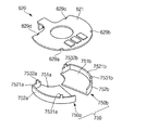
図19には本発明のまた他の実施例に係る二次電池に具備される支持構造物が保護回路モジュールと共に示されている。本実施例において、前記実施例と同じ構成要素に対しては同じ図面符号が使用される。また、本実施例において、前記実施例と同じ構成要素に対する詳細な説明は、重複した説明を避けるために省略される。本実施例は、前記図14〜図18を参照して説明した実施例に記載の構造物とは異なる支持構造物を備える。本実施例では、支持構造物を除いた他の構成は、前記図14〜図18を参照して説明した実施例と同一である。本実施例では、図19を参照して支持構造物についてのみ詳しく説明する。 FIG. 19 shows a support structure provided in a secondary battery according to another embodiment of the present invention together with a protection circuit module. In the present embodiment, the same reference numerals are used for the same components as in the previous embodiment. In the present embodiment, detailed description of the same components as those in the above embodiment is omitted to avoid redundant description. This embodiment includes a support structure different from the structure described in the embodiment described with reference to FIGS. In the present embodiment, the configuration other than the support structure is the same as that of the embodiment described with reference to FIGS. In this embodiment, only the support structure will be described in detail with reference to FIG.
図19を参照すると、支持構造物750は互いに分離された第1支持部材750aと第2支持部材750bを備える。
Referring to FIG. 19, the
第1支持部材750aは、第1底板751aと、第1底板751aから上方に延びた第1支持壁752aと、第1支持壁752aから上方に延びた多数の第1結合突起7531a、7532aとを備える。第1支持部材750aは、回路基板621の一側を支持する。
The
第1底板751aは、回路基板621の一側に対応する形状及び大きさを有する。第1底板751aは、両面テープのような付着手段によって、ベアセルの上端に付着する。
The
第1支持壁752aは、第1底板751aのエッジの一部から上方に延びて形成される。第1支持壁752aの上端7521aは、回路基板621のエッジを支持する。
The
多数の第1結合突起7531a、7532aは、第1支持壁752aの上端7521aから上にもっと延びて形成される。第1結合突起7531a、7532aは、それぞれ回路基板621の結合溝629a、629dと対応して位置する。第1結合突起7531a、7532aが回路基板621の結合溝629a、629dにそれぞれぴったり挿入される。
The plurality of
第2支持部材750bは、第2底板751bと、第2底板751bから上方に延びた第2支持壁752bと、第2支持壁752bから上方に延びた多数の第2結合突起7531b、7532bとを備える。第2支持部材750bは、回路基板621の他側を支持する。実質的に第2支持部材750bは、第1支持部材750aと対称の形状を有する。
The
第2底板751bは、回路基板621の他側に対応する形状及び大きさを有する。第2底板751aは、両面テープのような付着手段によって、ベアセルの上端に付着する。
The
第2支持壁752bは、第2底板751bのエッジの一部から上方に延びて形成される。第2支持壁752bの上端7521bは回路基板621のエッジを支持する。
The
多数の第2結合突起7531b、7532bは、第2支持壁752bの上端7521bから上にもっと延びて形成される。それぞれの第2結合突起7531b、7532bは、回路基板621の結合溝629b、629cと対応して位置する。第2結合突起7531b、7532bが、回路基板621の結合溝629b、629cにそれぞれぴったり挿入される。
The plurality of
支持構造物750が二つの支持部材750a、750bに分離形成されるので、支持構造物を必要な位置にのみ自由に設けることができるという長所がある。
Since the
その他の構成および作用は、図10〜図12に示された実施例と同一であるので、これについての詳細な説明は省略する。 Other configurations and operations are the same as those of the embodiment shown in FIGS. 10 to 12, and thus detailed description thereof will be omitted.
100 二次電池
110 円筒形ベアセル
120 保護回路モジュール
121 回路基板
130a、130b 第1電極タブ
140 第2電極用タブ
150 上部ケース
160 下部ケース
170 ラベル
DESCRIPTION OF
Claims (3)
第2電極を形成し、前記円筒形缶に結合される電極キャップを備える円筒形ベアセルと、
前記円筒形ベアセルの電極キャップと対向するように配置された回路基板を備える保護回路モジュールとを含み、
前記保護回路モジュールは、前記回路基板を前記円筒形ベアセルの第1電極に電気的に接続させる二つの第1電極タブと、前記回路基板を前記円筒形ベアセルの第2電極に電気的に接続させる第2電極タブとを備える二次電池であって、
前記円筒形ベアセルの円筒形缶の側壁には、内側に凹入したビーディング部が設けられ、
前記第1電極タブは、前記保護回路モジュールの回路基板に溶着されるベース部と、前記円筒形ベアセルの円筒形缶の側壁上部を覆うように延びた延長部と、前記円筒形ベアセルのビーディング部に挿入されるように形成された係止部とを備え、
前記第1電極タブの延長部は、互いに分離して延びた第1枝と第2枝を備え、
前記二つの第1電極タブは、前記回路基板の中心部を基準に互いに反対側に位置し、前記円筒形ベアセルの円筒形缶の側壁に溶接によって接合連結され、
前記第2電極タブは、前記保護回路モジュールの回路基板に溶着されるベース部と、前記ベース部から折り曲げられて前記円筒形ベアセル側に延びた延長部と、前記延長部から折り曲げられて前記円筒形ベアセルの電極キャップと溶接によって接合連結される連結部と、を備えることを特徴とする二次電池。 Forming a first electrode, a cylindrical can comprising a bottom plate and a side wall extending from the bottom plate ;
A cylindrical bare cell comprising an electrode cap forming a second electrode and coupled to the cylindrical can;
A protection circuit module comprising a circuit board disposed to face the electrode cap of the cylindrical bare cell,
The protection circuit module, and the two first electrode tab electrically connecting the circuit board to the first electrode of the cylindrical bare cell, thereby electrically connecting the circuit board to the second electrode of said cylindrical bare cell a secondary battery to obtain Bei and second electrode tabs,
The side wall of the cylindrical can of the cylindrical bare cell is provided with a beading portion recessed inside,
The first electrode tab includes a base part welded to a circuit board of the protection circuit module, an extension part extending to cover an upper side wall of a cylindrical can of the cylindrical bare cell, and a beading of the cylindrical bare cell A locking part formed to be inserted into the part,
The extension of the first electrode tab includes a first branch and a second branch extending separately from each other,
The two first electrode tabs are located on opposite sides of the center of the circuit board and are joined and connected to the side wall of the cylindrical can of the cylindrical bare cell by welding,
The second electrode tab includes a base portion welded to a circuit board of the protection circuit module, an extension portion bent from the base portion and extending toward the cylindrical bare cell, and bent from the extension portion to the cylindrical portion. A secondary battery comprising: an electrode cap of a shaped bare cell and a connecting portion joined and connected by welding.
Circuit board, the secondary battery according to claim 1 or 2, further comprising an external terminal provided for the charging and discharging of the protection circuit module.
Applications Claiming Priority (2)
| Application Number | Priority Date | Filing Date | Title |
|---|---|---|---|
| KR1020080132516A KR101016816B1 (en) | 2008-12-23 | 2008-12-23 | Secondary battery |
| KR10-2008-0132516 | 2008-12-23 |
Publications (2)
| Publication Number | Publication Date |
|---|---|
| JP2010153378A JP2010153378A (en) | 2010-07-08 |
| JP5190439B2 true JP5190439B2 (en) | 2013-04-24 |
Family
ID=41698292
Family Applications (1)
| Application Number | Title | Priority Date | Filing Date |
|---|---|---|---|
| JP2009279751A Active JP5190439B2 (en) | 2008-12-23 | 2009-12-09 | Secondary battery |
Country Status (4)
| Country | Link |
|---|---|
| EP (1) | EP2207233B1 (en) |
| JP (1) | JP5190439B2 (en) |
| KR (1) | KR101016816B1 (en) |
| CN (1) | CN101764251B (en) |
Families Citing this family (12)
| Publication number | Priority date | Publication date | Assignee | Title |
|---|---|---|---|---|
| JP2012182890A (en) * | 2011-02-28 | 2012-09-20 | Sharp Corp | Protective device for secondary battery, secondary battery device, and secondary battery |
| JP5885508B2 (en) * | 2012-01-06 | 2016-03-15 | 日立マクセル株式会社 | Battery unit |
| JP5938825B2 (en) * | 2012-03-27 | 2016-06-22 | オプテックス株式会社 | Reverse connection prevention structure for battery-powered object detection device |
| CN104681759B (en) * | 2015-02-05 | 2017-04-19 | 博科能源系统(深圳)有限公司 | Surface-mounted protecting plate and battery pack with same |
| ES2742726T3 (en) * | 2015-06-12 | 2020-02-17 | Fujian Nanping Nanfu Battery | Secondary electrochemical battery with built-in charging circuit |
| KR102246025B1 (en) * | 2017-01-05 | 2021-04-29 | 주식회사 엘지화학 | Cylindrical Battery Cell Comprising Safety Cap |
| KR102203249B1 (en) * | 2017-10-10 | 2021-01-13 | 주식회사 엘지화학 | Cylindrical Battery Cell Having Connection Cap |
| KR102455449B1 (en) * | 2018-10-05 | 2022-10-18 | 주식회사 엘지에너지솔루션 | Rechargeable battery |
| KR102593582B1 (en) * | 2019-12-19 | 2023-10-23 | 삼성에스디아이 주식회사 | Rechargeable battery |
| CN113488728B (en) * | 2021-07-02 | 2022-06-28 | 横店集团东磁股份有限公司 | Cylindrical battery |
| CN113644352A (en) * | 2021-07-21 | 2021-11-12 | 广州市金特电子科技有限公司 | Sleeve joint type battery structure and manufacturing method thereof |
| KR20240047837A (en) * | 2022-10-05 | 2024-04-12 | 주식회사 엘지에너지솔루션 | Cylindrical battery cell |
Family Cites Families (14)
| Publication number | Priority date | Publication date | Assignee | Title |
|---|---|---|---|---|
| JPH0963552A (en) * | 1995-08-24 | 1997-03-07 | Sanyo Electric Co Ltd | Battery pack |
| JP3272225B2 (en) * | 1995-12-19 | 2002-04-08 | 三洋電機株式会社 | Battery pack |
| JP3154279B2 (en) * | 1998-11-13 | 2001-04-09 | 松下電器産業株式会社 | Rechargeable battery |
| US6524739B1 (en) * | 1998-08-25 | 2003-02-25 | Matsushita Electric Industrial Co., Ltd. | Secondary battery |
| EP1250720B1 (en) * | 1999-06-21 | 2006-05-24 | The Board Of Trustees Of The University Of Illinois | Battery having a housing for electronic circuitry |
| US6437239B1 (en) * | 1999-09-24 | 2002-08-20 | Wilson Greatbatch, Ltd. | Protection device and method of determining exposure temperature |
| AU2003230322A1 (en) * | 2002-05-09 | 2003-11-11 | Mobypower Co., Ltd. | Rechargeable battery pack and manufacturing method thereof |
| KR20020070653A (en) * | 2002-05-09 | 2002-09-10 | (주) 모비파워 | Battery pack |
| KR100624977B1 (en) * | 2004-09-22 | 2006-09-15 | 삼성에스디아이 주식회사 | Pouch Type Li Secondary Battery |
| KR100670453B1 (en) * | 2005-05-18 | 2007-01-16 | 삼성에스디아이 주식회사 | Cylindrical Li Secondary Battery |
| KR100635730B1 (en) | 2005-06-28 | 2006-10-17 | 삼성에스디아이 주식회사 | Cylindrical li secondary battery and method for fabricating the same |
| KR100932224B1 (en) * | 2005-09-02 | 2009-12-16 | 주식회사 엘지화학 | Secondary battery with no welding connection |
| CN2793934Y (en) * | 2005-12-16 | 2006-07-05 | 徐敖奎 | Self-protection cylindrical lithium ion battery |
| JP5164491B2 (en) * | 2006-12-29 | 2013-03-21 | 三洋電機株式会社 | Cylindrical battery |
-
2008
- 2008-12-23 KR KR1020080132516A patent/KR101016816B1/en active IP Right Grant
-
2009
- 2009-12-09 JP JP2009279751A patent/JP5190439B2/en active Active
- 2009-12-21 EP EP09180100.1A patent/EP2207233B1/en active Active
- 2009-12-23 CN CN2009102620332A patent/CN101764251B/en active Active
Also Published As
| Publication number | Publication date |
|---|---|
| JP2010153378A (en) | 2010-07-08 |
| CN101764251A (en) | 2010-06-30 |
| KR101016816B1 (en) | 2011-02-21 |
| EP2207233A1 (en) | 2010-07-14 |
| EP2207233B1 (en) | 2020-05-06 |
| KR20100073761A (en) | 2010-07-01 |
| CN101764251B (en) | 2013-01-30 |
Similar Documents
| Publication | Publication Date | Title |
|---|---|---|
| JP5190439B2 (en) | Secondary battery | |
| US8481183B2 (en) | Secondary battery | |
| KR101127615B1 (en) | Battery pack | |
| US8703309B2 (en) | Battery pack of excellent productability and structural stability | |
| US7462417B2 (en) | Connecting structure for electrical connection of PCM and battery cell and secondary battery pack containing the same | |
| EP2320491B1 (en) | Battery pack | |
| KR101227870B1 (en) | Secondary battery pack having pcm case | |
| US9413039B2 (en) | Battery pack | |
| KR101001315B1 (en) | Secondary Battery Pack Having Excellent Energy Density and PCM Assembly therefor | |
| EP1906469A1 (en) | Battery Pack | |
| US8228033B2 (en) | Protective circuit board having groove and battery pack using the same | |
| US8669004B2 (en) | Battery pack | |
| EP2905824B1 (en) | Battery pack | |
| KR20130030285A (en) | Secondary battery pack | |
| KR20110024251A (en) | Secondary battery and method for manufacturing the same | |
| KR20130018127A (en) | Secondary battery pack of novel structure | |
| US8216706B2 (en) | Battery pack | |
| US20110250474A1 (en) | Secondary battery | |
| EP2270898B1 (en) | Battery | |
| US20110008653A1 (en) | Polymer battery pack | |
| US20110076520A1 (en) | Secondary battery | |
| US9257688B2 (en) | Battery pack having an inner frame and an outer frame | |
| KR101057534B1 (en) | Secondary battery | |
| CN111989812B (en) | Battery pack | |
| US8741452B2 (en) | Secondary battery |
Legal Events
| Date | Code | Title | Description |
|---|---|---|---|
| A131 | Notification of reasons for refusal |
Free format text: JAPANESE INTERMEDIATE CODE: A131 Effective date: 20120703 |
|
| A521 | Request for written amendment filed |
Free format text: JAPANESE INTERMEDIATE CODE: A523 Effective date: 20120927 |
|
| TRDD | Decision of grant or rejection written | ||
| A01 | Written decision to grant a patent or to grant a registration (utility model) |
Free format text: JAPANESE INTERMEDIATE CODE: A01 Effective date: 20130115 |
|
| A61 | First payment of annual fees (during grant procedure) |
Free format text: JAPANESE INTERMEDIATE CODE: A61 Effective date: 20130128 |
|
| FPAY | Renewal fee payment (event date is renewal date of database) |
Free format text: PAYMENT UNTIL: 20160201 Year of fee payment: 3 |
|
| R150 | Certificate of patent or registration of utility model |
Free format text: JAPANESE INTERMEDIATE CODE: R150 Ref document number: 5190439 Country of ref document: JP Free format text: JAPANESE INTERMEDIATE CODE: R150 |
|
| R250 | Receipt of annual fees |
Free format text: JAPANESE INTERMEDIATE CODE: R250 |
|
| R250 | Receipt of annual fees |
Free format text: JAPANESE INTERMEDIATE CODE: R250 |
|
| R250 | Receipt of annual fees |
Free format text: JAPANESE INTERMEDIATE CODE: R250 |
|
| R250 | Receipt of annual fees |
Free format text: JAPANESE INTERMEDIATE CODE: R250 |
|
| R250 | Receipt of annual fees |
Free format text: JAPANESE INTERMEDIATE CODE: R250 |
|
| R250 | Receipt of annual fees |
Free format text: JAPANESE INTERMEDIATE CODE: R250 |
|
| R250 | Receipt of annual fees |
Free format text: JAPANESE INTERMEDIATE CODE: R250 |
|
| R250 | Receipt of annual fees |
Free format text: JAPANESE INTERMEDIATE CODE: R250 |
|
| R250 | Receipt of annual fees |
Free format text: JAPANESE INTERMEDIATE CODE: R250 |