JP5187792B2 - LED lighting device - Google Patents
LED lighting device Download PDFInfo
- Publication number
- JP5187792B2 JP5187792B2 JP2012049385A JP2012049385A JP5187792B2 JP 5187792 B2 JP5187792 B2 JP 5187792B2 JP 2012049385 A JP2012049385 A JP 2012049385A JP 2012049385 A JP2012049385 A JP 2012049385A JP 5187792 B2 JP5187792 B2 JP 5187792B2
- Authority
- JP
- Japan
- Prior art keywords
- led
- end cap
- fluorescent lamp
- lamp
- power
- Prior art date
- Legal status (The legal status is an assumption and is not a legal conclusion. Google has not performed a legal analysis and makes no representation as to the accuracy of the status listed.)
- Active
Links
Images


Description
本発明は、LED照明装置に関し、特に、既設の直管型蛍光灯灯具にそのまま取り付け可能なLED照明装置に関する。 The present invention relates to an LED lighting device, and more particularly to an LED lighting device that can be directly attached to an existing straight tube fluorescent lamp.
近年、蛍光灯に代わってLEDランプが急速に普及しつつある。LEDランプは、蛍光灯に比べて消費電力が少なく、寿命も長いといった長所がある。また、このLEDランプを取り付ける際に、既設の蛍光灯灯具をそのまま用いて、ランプだけを蛍光ランプからLEDランプに交換するだけでLED照明装置として設置することを可能にしたものも見られる。例えば特許文献1には、蛍光管のワット数に応じた規定の長さに設定され、蛍光管を取り外してそのまま既設の蛍光灯器具に簡単に取付けることができる蛍光灯型LED照明装置が開示されている(特許文献1参照)。このような蛍光灯代替型のLED照明装置は、既設の蛍光灯器具をそのまま有効利用するものであるため、比較的簡単な工事で設置することができ、設置費用も安価ですみ、資源の無駄遣いを防ぐことができるものであり、また、それまでの蛍光灯のときの部屋の雰囲気を維持することができるといった長所がある。 In recent years, LED lamps are rapidly spreading in place of fluorescent lamps. LED lamps have the advantages of lower power consumption and longer life than fluorescent lamps. In addition, when the LED lamp is mounted, it is possible to use an existing fluorescent lamp as it is, and it is possible to install the LED lamp as an LED illumination device by simply replacing the lamp from the fluorescent lamp to the LED lamp. For example, Patent Document 1 discloses a fluorescent lamp type LED lighting apparatus that is set to a prescribed length corresponding to the wattage of a fluorescent tube, and that can be easily attached to an existing fluorescent lamp fixture by removing the fluorescent tube. (See Patent Document 1). Such a fluorescent lamp alternative type LED lighting apparatus can be installed with relatively simple construction because it uses an existing fluorescent lamp fixture as it is, and installation costs are low, and resources are wasted. In addition, there is an advantage that the atmosphere of the room at the time of the conventional fluorescent lamp can be maintained.
ところで、蛍光灯には、一般に、ランプ電流値を制御するとともにランプの点灯に必要な始動電圧と電極に適正な予熱電圧を供給するための安定器が備えられている。例えば、ラピッドスタート型の蛍光灯の場合、始動補助導体を持ったラピッドスタート形ランプと、予熱巻線を備えた電磁安定器の一種であるラピッド安定器との組み合わせによりランプの点灯を行うようにしている。また、インバータ式の蛍光灯の場合、高周波点灯用の電子式安定器を用いたインバータ回路によりランプの点灯を行うようにしている。 By the way, the fluorescent lamp is generally provided with a ballast for controlling the lamp current value and supplying a starting voltage necessary for lighting the lamp and an appropriate preheating voltage to the electrodes. For example, in the case of a rapid start type fluorescent lamp, the lamp is lit by a combination of a rapid start type lamp having a starting auxiliary conductor and a rapid ballast which is a kind of electromagnetic ballast having a preheating winding. ing. In the case of an inverter type fluorescent lamp, the lamp is lit by an inverter circuit using an electronic ballast for high frequency lighting.
しかしながら、従来の蛍光灯型LED照明装置は、単に蛍光ランプをLEDランプに交換するだけであり、LEDランプを従来の蛍光灯灯具に電気的に接続して使用するものであるため、蛍光灯灯具に備えられた安定器をそのまま使用して点灯動作等を行うものとなっていた。このため、LED照明装置自体に備えられているAC/DCコンバーターと蛍光灯灯具の安定器とが重畳的に作用することにより火災事故などを引き起こすおそれがあり、この結果、電気用品安全法(いわゆるPSE法)に基づく技術基準をクリアすることも困難であった。また、かかる火災事故などが発生した場合に、その原因が特定しにくいことから、責任の所在が不明確になるという問題もあった。さらに、かかる安全上の問題のほかにも、蛍光灯灯具の安定器自体も7−11W程度の電力を消費するため、無駄に電力を消費してしまうという問題やせっかく長寿命のLEDランプを取り付けても安全器自体の寿命により故障の原因となりやすいといった問題があった。 However, the conventional fluorescent lamp type LED lighting device simply replaces the fluorescent lamp with the LED lamp, and is used by electrically connecting the LED lamp to the conventional fluorescent lamp. The ballast provided in the above is used as it is for lighting operation and the like. For this reason, the AC / DC converter provided in the LED lighting device itself and the ballast of the fluorescent light lamp may act in a superimposed manner to cause a fire accident or the like. It was also difficult to clear the technical standards based on the PSE method. In addition, when such a fire accident occurs, it is difficult to identify the cause, and there is a problem that the responsibility is unclear. Furthermore, in addition to such safety problems, the fluorescent lamp ballast itself consumes about 7-11 W of power, so there is a problem of wasteful power consumption and a long-life LED lamp is attached. However, there is a problem that the life of the safety device itself is likely to cause a failure.
このような安全上の問題や消費電力の無駄の問題を回避するため、蛍光ランプからLEDランプへの交換に際して、蛍光灯灯具に備えられた安定器を取り外すという方法が用いられることもあった。しかし、この方法は、工事に手間と費用がかかり、特に一般家庭では簡単に行うことができないという問題があった。このような問題点は、比較的簡単な工事で設置することができ設置費用も安価ですむという折角の蛍光灯代替型LED照明装置の長所を減殺するものであり、LED照明装置の一般家庭への普及の妨げともなりかねないものである。 In order to avoid such a safety problem and a problem of wasted power consumption, a method of removing a ballast provided in a fluorescent lamp device may be used when replacing a fluorescent lamp with an LED lamp. However, this method has a problem in that it requires labor and cost for construction, and cannot be easily performed particularly in ordinary households. Such a problem reduces the advantage of the fluorescent lamp alternative type LED lighting device that can be installed with relatively simple construction and is low in installation cost. It may be a hindrance to the spread of
そこで、本発明の解決すべき課題は、蛍光灯からLED照明装置への換装に際し、比較的簡単な工事で設置することができ、設置費用も安価ですみ、資源の無駄遣いを防ぐこともできることに加え、それまでの蛍光灯のときの部屋の雰囲気を維持することができるといった長所を維持した上で、さらに安全上の問題や消費電力の無駄の問題を回避することができるLED照明装置を提供することにある。 Therefore, the problem to be solved by the present invention is that when replacing a fluorescent lamp with an LED lighting device, it can be installed with relatively simple construction, the installation cost is low, and the waste of resources can be prevented. In addition, while maintaining the advantages of maintaining the atmosphere of the room when using fluorescent lamps up to that point, an LED lighting device that can further avoid safety problems and power consumption problems is provided. There is to do.
以上の課題を解決するため、第一の発明は、直管蛍光ランプ形状を有し、複数のLED素子を配置したLEDランプ部と、前記LEDランプ部の両端にそれぞれ備えられ、直管型蛍光灯灯具のソケットに取り付け可能な支持ピンを備えた一対のエンドキャップ部と、電源からの電力線に接続された電源コネクターを接続可能な本体コネクター部とを有するLED照明装置を提供する。 In order to solve the above problems, the first invention has a straight tube fluorescent lamp shape, and is provided with an LED lamp part in which a plurality of LED elements are arranged, and both ends of the LED lamp part. Provided is an LED lighting device having a pair of end caps having support pins that can be attached to a socket of a lamp and a main body connector that can be connected to a power connector connected to a power line from a power source.
また、第二の発明は、第一の発明を基礎として、前記本体コネクター部は、前記一対のエンドキャップ部のうちの一方の近傍に備えられていることを特徴とするLED照明装置を提供する。 Moreover, 2nd invention provides the LED illuminating device characterized by the said main body connector part being provided in the vicinity of one of said pair of end cap parts on the basis of 1st invention. .
また、第三の発明は、第一または第二の発明を基礎として、前記LEDランプ部の前記複数のLED素子のそれぞれは、直管軸方向に並べられるとともに、直管軸に垂直な方向で隣接するLED素子どうしが重なるように斜めに配置されることを特徴とするLED照明装置を提供する。 Moreover, 3rd invention is based on 1st or 2nd invention, and each of these LED element of the said LED lamp part is arranged in a straight pipe axis direction, and is perpendicular | vertical to a straight pipe axis. Provided is an LED illuminating device which is disposed obliquely so that adjacent LED elements overlap each other.
さらに、第四の発明は、第一から第三のいずれか一の発明を基礎として、前記エンドキャップ部は、互いに独立して回動可能に取り付けられている二つの部材から構成されていることを特徴とするLED照明装置を提供する。 Further, according to a fourth aspect of the invention, on the basis of any one of the first to third aspects, the end cap portion is composed of two members that are rotatably attached to each other. An LED lighting device is provided.
本発明により、蛍光灯からLED照明装置への換装に際し、比較的簡単な工事で設置することができ、設置費用も安価ですみ、資源の無駄遣いを防ぐこともできることに加え、それまでの蛍光灯のときの部屋の雰囲気を維持することができるといった長所を維持した上で、さらに安全上の問題や消費電力の無駄の問題を回避することができるLED照明装置を提供することが可能となる。 According to the present invention, when replacing a fluorescent lamp with an LED lighting device, it can be installed with relatively simple construction, installation cost is low, and waste of resources can be prevented. It is possible to provide an LED lighting device that can avoid the problem of safety and the waste of power consumption while maintaining the advantage that the atmosphere of the room can be maintained.
0100 LED照明装置
0110 LEDランプ部
0111 管体
0112 上側半体
0113 下側半体
0120a エンドキャップ部(本体コネクター部側)
0120b エンドキャップ部(本体コネクター部側でない方の側)
0122 支持ピン
0123 切欠き部
0130 本体コネクター部(ピン)
0140 電力線(本体コネクター部からLEDランプ部に至る部分)
0150 電力線(天井等から電源コネクターに至る部分)
0160 電源コネクター
0160a ピン受け孔
0212a 張り出し部分
0270 円形状基板
0100
0120b End cap (the side that is not the main body connector)
0122
0140 Power line (portion from main body connector part to LED lamp part)
0150 Power line (from the ceiling etc. to the power connector)
0160
以下に、本発明の実施例を説明する。実施例と請求項の相互の関係は以下のとおりである。実施例1は主に請求項1、請求項2などに関し、実施例2は主に請求項3などに関し、実施例3は主に請求項4などに関する。なお、本発明はこの実施例に何ら限定されるものではなく、その要旨を逸脱しない範囲において、種々なる態様で実施しうる。 Examples of the present invention will be described below. The relationship between the embodiments and the claims is as follows. The first embodiment mainly relates to claims 1 and 2, the second embodiment mainly relates to claim 3, and the third embodiment mainly relates to claim 4. In addition, this invention is not limited to this Example at all, and can be implemented in various modes without departing from the gist thereof.
<概要> <Overview>
本実施例のLED照明装置は、直管蛍光ランプ形状を有し、複数のLED素子を配置したLEDランプ部と、前記LEDランプ部の両端にそれぞれ備えられ、直管型蛍光灯灯具のソケットに取り付け可能な支持ピンを備えた一対のエンドキャップ部と、電源からの電力線に接続された電源コネクターを接続可能な本体コネクター部とを有するLED照明装置である。また、本体コネクター部が前記一対のエンドキャップ部のうちの一方の近傍に備えられているものも本実施例のLED照明装置に含まれる。 The LED illumination device of the present embodiment has a straight tube fluorescent lamp shape, and is provided with an LED lamp unit in which a plurality of LED elements are arranged, and both ends of the LED lamp unit, and is attached to a socket of a straight tube type fluorescent lamp. It is an LED lighting device having a pair of end cap portions having support pins that can be attached and a main body connector portion to which a power connector connected to a power line from a power source can be connected. Also, the LED illumination device of this embodiment includes a main body connector portion provided in the vicinity of one of the pair of end cap portions.
<構成> <Configuration>
(照明装置全般) (General lighting equipment)
図1は、本実施例に係るLED照明装置の形状の一例を示す斜視図である。本図に示すように、本実施例に係るLED照明装置0100は、LEDランプ部0110と、エンドキャップ部0120と、本体コネクター部0130とからなる。
FIG. 1 is a perspective view showing an example of the shape of the LED lighting device according to the present embodiment. As shown in the figure, the
(LEDランプ部) (LED lamp part)
LEDランプ部は、直管蛍光ランプ形状を有し、複数のLED素子を配置したものである。本発明において「直管蛍光ランプ」とは、従来型の直管蛍光ランプをいい、より詳細には、JISC7617−2「直管蛍光ランプ−第2部:性能規定」の2.3.1「データシートのリスト」に規定された直管蛍光ランプをいう。このように本発明におけるLEDランプ部の形状を従来型の直管蛍光ランプ形状としているのは、かかる従来型の直管蛍光ランプをとりつけるための直管型蛍光灯灯具にそのまま取り付けることができるようにするためである。即ち、本発明において「直管型蛍光灯灯具」とは、上述のような従来型の直管蛍光ランプを取り付けて使用することが可能な形状、寸法、機能を有する蛍光灯灯具をいう。 The LED lamp portion has a straight tube fluorescent lamp shape, and a plurality of LED elements are arranged. In the present invention, the “straight tube fluorescent lamp” refers to a conventional straight tube fluorescent lamp, and more specifically, 2.3.1 “JIS C7617-2“ Straight tube fluorescent lamp—Part 2: Performance specification ”. This refers to the straight tube fluorescent lamp specified in the “List of data sheets”. Thus, the shape of the LED lamp portion in the present invention is a conventional straight tube fluorescent lamp shape so that it can be directly attached to a straight tube fluorescent lamp for mounting such a conventional straight tube fluorescent lamp. It is to make it. That is, in the present invention, the “straight tube fluorescent lamp” refers to a fluorescent lamp having a shape, size, and function that can be used with the conventional straight tube fluorescent lamp as described above.
このようにLEDランプ部を直管蛍光ランプ形状を有するものとすることにより、比較的簡単な工事でLED照明装置を設置することができ、設置費用も安価ですみ、資源の無駄遣いを防ぐこともできる。また、それまでの蛍光灯のときの部屋の雰囲気を維持することもできるといった蛍光灯代替型LED照明装置の長所を発揮することが可能となる。 By making the LED lamp portion into a straight fluorescent lamp shape in this way, it is possible to install the LED lighting device with relatively simple construction, the installation cost is low, and the waste of resources can be prevented. it can. In addition, it is possible to exhibit the advantages of the fluorescent lamp alternative type LED lighting device that can maintain the atmosphere of the room when the fluorescent lamp is used.
なお、次に述べるように、LEDランプ部の両端には一対のエンドキャップ部が備えられ、その支持ピン(直管蛍光ランプの端子に相当)によって従来型の蛍光灯灯具に取り付けられるように構成されるので、本発明のLEDランプ部の管長はこの一対のエンドキャップ部を含めて従来型の蛍光灯灯具に取り付け可能な寸法に規制される。 In addition, as described below, a pair of end cap portions are provided at both ends of the LED lamp portion, and are configured to be attached to a conventional fluorescent lamp by means of support pins (corresponding to terminals of a straight tube fluorescent lamp). Therefore, the tube length of the LED lamp portion of the present invention is restricted to a size that can be attached to a conventional fluorescent lamp including the pair of end cap portions.
LEDランプ部の具体的構成は、公知の直管蛍光ランプ形状のLEDランプと同様であり、例えば、透明ないし半透明のプラスチック製の円筒形状の管体0111の内部に電源から回路基板を介して給電されて発光する複数のLED素子を、回路基板上にアレイ状に配置する。円筒形状の管体は上述のように単一素材のものであってもよいが、例えば、上側半体をアルミニウムなどの金属製、下側半体をポリカーボネイトなどのプラスチック製にするといったように異なる素材を組み合わせたものであってもよい。図1に示したものはこの例であり、管体0111は金属製の上側半体0112とプラスチック製の下側半体0113を組み合わせたものである。この例の場合には、上側半体に金属製素材を用いることで、管体の強度を増すことや、金属製部分を回路基板に接触させることで、発光に伴い発生する熱を回路基板から金属製部分に伝導させて放熱効果を高めることができる。
The specific configuration of the LED lamp unit is the same as that of a known straight tube fluorescent lamp-shaped LED lamp. For example, a
また、従来のLED照明装置と同様、本発明のLED照明装置にも、AC/DCコンバーター、コンデンサーなどが備えられ、電源から入力された電力は、AC/DCコンバーターによって直流に変換され、コンデンサーによって平滑化されて各LED素子に供給される。AC/DCコンバーターなどの配置場所は適宜設計されればよいが、例えば、LEDランプ部を構成する管体の内部(例えば図1に示される上側半体内)に配置される。 Similarly to the conventional LED lighting device, the LED lighting device of the present invention is also provided with an AC / DC converter, a capacitor, etc., and the power input from the power source is converted into a direct current by the AC / DC converter, and the capacitor It is smoothed and supplied to each LED element. The arrangement location of the AC / DC converter or the like may be appropriately designed. For example, the AC / DC converter is arranged inside the tube (for example, the upper half shown in FIG. 1) constituting the LED lamp unit.
なお、図1に示したLEDランプ部の形状はあくまで一例であり、本発明に係るLEDランプ部の形状が本図に示すものに限られないことはいうまでもない。エンドキャップ部、本体コネクター部の形状についても同様である。これらは他図においても同様である。 The shape of the LED lamp portion shown in FIG. 1 is merely an example, and it goes without saying that the shape of the LED lamp portion according to the present invention is not limited to that shown in the drawing. The same applies to the shapes of the end cap part and the main body connector part. These are the same in other drawings.
図2Aは、図1の分解斜視図である。説明の便宜上、図1で右側に現れるエンドキャップ部0120bの図示は省略した。本図においてLEDランプ部0210を構成する管体0211は、金属製の上側半体0212と、プラスチック製の下側半体0213とに分割されている。両半体は、例えば接着剤で接合される。また、本図に示す例では、管体の金属製部分が内側への張り出し部分0212aを備えており、この部分で回路基板(図示を省略)に接触することで、放熱効果を高めることを可能にしている。
FIG. 2A is an exploded perspective view of FIG. For convenience of explanation, illustration of the
LEDランプ部とエンドキャップ部との接合も例えば接着剤を用いればよい。あるいは、LEDランプ部とエンドキャップ部が独立して回動可能になるようにしてもよい。 For example, an adhesive may be used for joining the LED lamp part and the end cap part. Or you may make it an LED lamp part and an end cap part turn independently.
さらに、本図に示すように、LEDランプ部0210とエンドキャップ部0220aとの間に、例えばポリ塩化ビフェニールなどのプラスチックを素材とする円形状基板0270を介在させて両者を接合するようにしてもよい。かかる基板を介在させることで、上述のようにLEDランプ部とエンドキャップ部が独立して回動可能になるようにした場合に、電力線の回路基板との接触部分が断線しにくくなるという効果がある。
Further, as shown in the figure, a
(エンドキャップ部) (End cap part)
図1に戻り、エンドキャップ部0120a、0120bは、前記LEDランプ部の両端にそれぞれ備えられ直管型蛍光灯灯具のソケットに取り付け可能な支持ピンを備えたものである。エンドキャップ部の第一の目的は、LEDランプを従来型の蛍光灯灯具にそのまま取り付けることができるようにすることにある。従って、エンドキャップ部は、LEDランプとほぼ同一の管径を有する円筒形状の部材であり、その長さは、当該エンドキャップを両端に備えたLEDランプ部を従来型の蛍光灯灯具にそのまま取り付けることができる長さに規制される。エンドキャップ部の材質に特に限定はないが、例えば金属製のものが用いられる。
Returning to FIG. 1, the
一対のエンドキャップ部のそれぞれの外側(従来型の蛍光灯灯具のソケット側)の端部には支持ピン0122が備えられる。この支持ピンは直管型蛍光灯灯具のソケットにLEDランプ部およびエンドキャップ部をそのまま取り付けることを可能にするためのものである。即ち、この支持ピンは、公知の蛍光灯型LED照明装置における従来型の蛍光灯灯具のソケットに電気的に接続するために備えられる端子に相当するものである。従って、支持ピンの寸法・形状は、従来型の蛍光灯灯具のソケットに取り付け可能な寸法・形状を有するものであり、具体的にはJISC7601「蛍光ランプ(一般照明用)」に規定されたG13に係る口金が該当する。ただし、公知の蛍光灯型LED照明装置の端子との違いは、支持ピンは従来型の蛍光灯灯具のソケットに電気的に接続されるのではなく、単に従来型の蛍光灯灯具をLEDランプ部を保持するための支持具として利用するために接続されるのにすぎない点にある。 Support pins 0122 are provided at the outer ends of the pair of end cap portions (on the socket side of a conventional fluorescent lamp). This support pin is for making it possible to attach the LED lamp part and the end cap part as they are to the socket of the straight tube type fluorescent lamp. That is, this support pin corresponds to a terminal provided for electrical connection to a socket of a conventional fluorescent lamp device in a known fluorescent lamp type LED lighting device. Accordingly, the size and shape of the support pin has a size and shape that can be attached to a socket of a conventional fluorescent lamp, and specifically, G13 defined in JIS C7601 “Fluorescent lamp (for general illumination)”. This applies to the caps related to. However, the difference from the terminal of the known fluorescent lamp type LED lighting device is that the support pin is not electrically connected to the socket of the conventional fluorescent lamp unit, but simply replaces the conventional fluorescent lamp unit with the LED lamp unit. It is only connected to be used as a support for holding.
エンドキャップ部の第二の目的は、特に、本体コネクター部から回路基板に至る電力線の一部をその内部に収納してこれを保護することにある。この目的は、特に本体コネクター部が一対のエンドキャップ部のうちの一方の近傍に備えられている場合に典型的に現れるものである。かかる目的のため、エンドキャップ部は内部に電力線の一部を収納するためのスペースを有していることが望ましい。この場合、別図を用いて後述するように、本体コネクター部を構成するピンが、例えばエンドキャップ部の壁面に埋め込まれる形で立設され、エンドキャップ部の内壁面側に現れる当該ピンの頭頂部(ピン頭)に接続された電力線が、エンドキャップ部内部のスペース内に展張され、さらにエンドキャップ部とLEDランプ部との接続部分の開口部分を介してLEDランプ部の回路基板に至ることになる。 The second purpose of the end cap part is particularly to house and protect a part of the power line from the main body connector part to the circuit board. This object typically appears particularly when the main body connector portion is provided near one of the pair of end cap portions. For this purpose, the end cap part desirably has a space for accommodating a part of the power line therein. In this case, as will be described later with reference to another drawing, the pin constituting the main body connector portion is erected, for example, embedded in the wall surface of the end cap portion, and the head of the pin appearing on the inner wall surface side of the end cap portion. The power line connected to the top part (pin head) is extended in the space inside the end cap part, and further reaches the circuit board of the LED lamp part through the opening part of the connection part between the end cap part and the LED lamp part. become.
また、エンドキャップ部が互いに独立して回動可能に取り付けられている二つの部材から構成されていてもよい。かかる場合の具体的な構成及びその目的については、別の実施例にて後述する。 Moreover, the end cap part may be comprised from the two members attached so that rotation was mutually independent. The specific configuration and purpose in such a case will be described later in another embodiment.
また、本体コネクター部を一対のエンドキャップ部のうちの一方の近傍に備える場合、図1、図2Aの例に示したように、当該一方のエンドキャップ部(便宜上エンドキャップ部(本体コネクター部側)といい、図1では、左側に現れるエンドキャップ部0120aがこれに相当する)には、同図に示すように上端付近に切欠き部0123が設けられていてもよい。この切欠き部は、本体コネクター部0130を構成する一対のピンを立設するためのスペースを提供するとともに、本体コネクター部を電源コネクターに接続する際に電源コネクターをぴったりと嵌め込むことができるためのスペースを提供するためのものである。かかる構成の詳細およびその効果については、後述の本体コネクター部の説明の中で改めて述べる。
When the main body connector portion is provided in the vicinity of one of the pair of end cap portions, as shown in the examples of FIGS. 1 and 2A, the one end cap portion (for convenience, the end cap portion (the main body connector portion side) In FIG. 1, the
なお、図2Aに示したようにLEDランプ部とエンドキャップ部との間に上述の円形状基板0270を介在させる場合には、電力線は、この基板に設けられた小孔0270aを介して回路基板に導かれることになる(図2Aでは小孔の形状をわかりやすく示すため、一方の孔にのみ貫通する電力線0240を図示した)。
2A, when the
図3は本実施例のLED照明装置のエンドキャップ部の形状の一例を示す図であって、図2Aに現れるエンドキャップ部(本体コネクター部側)0220aを同図の概ね右側やや下方向からみた斜視図である。本図に現れているように、エンドキャップ部0320の内部には電力線を収納するためのスペース0321が設けられ、ここにエンドキャップ部の切欠き部0323(本図ではエンドキャップ部を内側から見ているので、エンドキャップ部のスペース内に張り出した蒲鉾型の張出し部分として現れる)に立設された本体コネクター部の一対のピン0330(本図にはエンドキャップ部の内壁面に埋め込まれたピン頭の頂面が現れる)にそれぞれ接続された電力線の一部0340が収納されている。図示は省略したが、この電力線はエンドキャップ部の開口部(本図では上端面に現れている略円形の開口部分)からLEDランプ部へと導かれる(なお、実際には本図に現れるべき図1に示した支持ピン0122のピン頭部分の図示は、煩雑を避けるために省略した)。
FIG. 3 is a diagram showing an example of the shape of the end cap portion of the LED lighting device of the present embodiment, and the end cap portion (main body connector portion side) 0220a appearing in FIG. 2A is seen from the slightly right side of the drawing. It is a perspective view. As shown in this figure, a
(本体コネクター部) (Main unit connector)
再び図1に戻り、本体コネクター部0130は、電源から電力を入力するためのものである。電源からの電力の入力は、典型的には一次電源からの電力の入力であり、天井や壁などの電灯線(電力線)から直に電力を取り入れるという意味である。このため、本図の例でも、本体コネクター部は、一次電源から天井や壁などを介して引き出された電力線0150に接続された電源コネクター0160を接続可能に構成されている。ただし、本体コネクター部は、例えば停電などの際にバッテリーから電力を入力するためのものでもあってよい。
Returning to FIG. 1 again, the main
本体コネクター部は、電源コネクターとともに一対のコネクターのそれぞれの一方を構成するものである。本体コネクター部と電源コネクターの接続のしかたは、両者が電気的に接続されるものであれば特に限定はないが、例えば、一方が一対のピンを備えた雌コネクターであり、もう一方がこれに対応するピン受け孔を備えた雄コネクターであるものが考えられる。この場合には、本体コネクター部が雌コネクターであり、電源コネクターが雄コネクターであることが望ましい。なぜなら、このようにすることで、取り付け作業時などにおける感電のおそれ等を防いで安全性を高めることができるとともに、わざわざLED照明装置の本体側にコネクター用のスペースを設ける必要がないからである。 The main body connector portion constitutes one of the pair of connectors together with the power connector. There is no particular limitation on the method of connecting the main body connector and the power supply connector as long as they are electrically connected. For example, one is a female connector having a pair of pins, and the other is connected to this. A male connector with a corresponding pin receiving hole is conceivable. In this case, it is desirable that the main body connector portion is a female connector and the power connector is a male connector. This is because, by doing so, it is possible to prevent the risk of electric shock at the time of installation work and the like and to improve safety, and it is not necessary to provide a space for the connector on the main body side of the LED lighting device. .
前述のように、従来の蛍光灯型LED照明装置とは異なり、本発明では蛍光灯灯具のソケットからは電力が入力されないが、これに代えてこの本体コネクター部を介して電源から直接電力が入力される。このように電源から直接電力を入力するため、蛍光灯灯具に備えられた安定器を介さずに給電が行われることになる。従って、LEDランプ自体に備えられているAC/DCコンバーターと蛍光灯灯具の安定器が重畳的に作用することにより火災事故などを引き起こすおそれを回避することができる。また、それゆえにわざわざ蛍光灯灯具の安定器を取り外す必要もなくなる。 As described above, unlike the conventional fluorescent lamp type LED lighting device, in the present invention, power is not input from the socket of the fluorescent lamp, but instead, power is directly input from the power source via the main body connector. Is done. Since power is directly input from the power supply in this way, power is supplied without going through a ballast provided in the fluorescent lamp. Accordingly, it is possible to avoid the possibility of causing a fire accident or the like by the AC / DC converter and the ballast of the fluorescent lamp fixture provided in the LED lamp itself acting in a superimposed manner. It is therefore unnecessary to remove the ballast of the fluorescent lamp.
電源からの入力は、典型的には、ホット側、コールド側の双方からの電力線に接続された単一の電源コネクターに対して単一のソケットを接続することで行われる。このようにすることで、本体コネクター部の配置位置を一対のエンドキャップ部のうちの一方の近傍に備えるように構成することができる。これにより、例えば本体コネクター部をエンドキャップ部から引き出された電力線の先に取り付ける場合においては、エンドキャップ部から露出する電力線の長さを短くすることができるので、LED照明装置への換装作業が容易になり、また、見た目もすっきりさせることが可能となる。 Input from the power source is typically performed by connecting a single socket to a single power connector that is connected to the power lines from both the hot and cold sides. By doing in this way, it can comprise so that the arrangement position of a main-body connector part may be provided in the vicinity of one of a pair of end cap parts. Thereby, for example, when attaching the main body connector part to the tip of the power line drawn out from the end cap part, the length of the power line exposed from the end cap part can be shortened. It becomes easy and the appearance can be made clear.
本体コネクター部の形状には特に限定はなく、例えば、単にエンドキャップ部に設けた小孔から引き出された二本の電力線の先端にホット側、コールド側それぞれの端子を取り付けただけのものであってもよい。ただし、好適な一例としては、図1、2に示した例のように、エンドキャップ部の上端付近に切欠き部を設け、ここに本体コネクター部を構成する一対のピンを立設するようにしたものが考えられる。この場合には、本体コネクター部を電源コネクターに接続する際には、電源コネクターがエンドキャップ部の当該切欠き部にぴったりと嵌め込まれる。このため、切欠き部の形状、寸法と電源コネクターの形状、寸法は、互いにぴったりと嵌まり合う形状、寸法に設計される。さらに言えば、この形状は、電源コネクターをエンドキャップ部の切欠き部に嵌め込んだときに、LEDランプ部、エンドキャップ部、電源コネクターを合わせた全体の形状が直管蛍光ランプ形状になるようなもの(平たく言えば、電源コネクターは円筒形状のエンドキャップ部から一部を切り取った形状であるもの)が望ましい。 There is no particular limitation on the shape of the main body connector part. For example, the hot-side and cold-side terminals are simply attached to the ends of the two power lines drawn out from the small holes provided in the end cap part. May be. However, as a preferred example, as in the example shown in FIGS. 1 and 2, a notch portion is provided near the upper end of the end cap portion, and a pair of pins constituting the main body connector portion are erected here. Can be considered. In this case, when the main body connector portion is connected to the power connector, the power connector is fitted into the notch portion of the end cap portion. For this reason, the shape and size of the notch and the shape and size of the power connector are designed to fit and fit closely together. Furthermore, this shape is such that when the power connector is fitted into the notch portion of the end cap portion, the overall shape of the LED lamp portion, end cap portion, and power connector becomes a straight tube fluorescent lamp shape. It is desirable that the power connector is a shape obtained by cutting a part of the cylindrical end cap portion.
図2Aの例に即して言えば、電源コネクター0260の形状、寸法は、これをエンドキャップ部(本体コネクター部側)0220aの上端付近に設けられた切欠き部0223に嵌め込んだときに、これらを合わせた形状がちょうど一個の円筒の形状になるような形状、寸法である。また、切欠き部に立設された本体コネクター部を構成するピン0230と、電源コネクターのピン受け孔0260aは、電源コネクターと切欠き部をぴったりと嵌め込むことができる位置に設けられる。図2Aにおいて、切欠き部0223の上方に描かれた二点鎖線0224は、電源コネクターを切欠き部に嵌め込んだときの電源コネクターの仮想位置を示しており、電源コネクターとエンドキャップ部(本体コネクター部側)を合わせた形状がちょうど一個の円筒の形状になることが示されている。
Speaking of the example of FIG. 2A, the shape and dimensions of the
なお、図示は省略したが、このピン受け孔には、電源からの電力線(天井等から電源コネクターに至る部分)0250に接続されたピン受け端子が配置され、本体コネクター部のピンをピン受け孔に挿入したときに、ピンがピン受け端子に接触することで、電源コネクターから本体コネクター部に電力供給がなされるようになっている。 Although not shown, the pin receiving hole is provided with a pin receiving terminal connected to a power line (a portion extending from the ceiling or the like to the power connector) 0250 from the power source, and the pin of the main body connector portion is connected to the pin receiving hole. When the pin is inserted into the connector, the pin comes into contact with the pin receiving terminal so that power is supplied from the power connector to the main body connector portion.
エンドキャップ部、本体コネクター部(ピン)、電源コネクターの配置、形状、寸法をこのようなものにすれば、エンドキャップ部から露出する電力線を全くなくすことができるため、LED照明装置への換装作業がより一層容易になり、また、見た目もさらにすっきりさせることが可能となる。 If the arrangement, shape, and dimensions of the end cap part, main body connector part (pin), and power supply connector are such, the power line exposed from the end cap part can be eliminated altogether. Can be made easier, and the appearance can be made clearer.
図2B、図2Cは、本実施例に係るLED照明装置の形状の図1とは別の一例を示す斜視図である(図示の便宜上、図2Cは、図1とは逆にエンドキャップ部(本態コネクター側)が右側に現れる向きに示した)。図1、図2Aに示したのとは異なる形状の本体コネクター部の好適な一例としては、図2Bに示すように、エンドキャップ部0220aの切欠き部0223に設けた本体コネクター部0230に対して、電源コネクター0260を略左右方向(概ね図に矢印A方向又はA´方向で示す方向)から接続するようにしたものであってもよい。本図の例では、雄コネクターである電源コネクターを雌コネクターである本体コネクター部に対して太矢印aに示すように挿入して接続する。あるいは、図2Cに示すように、エンドキャップ部0220aの切欠き部0223に設けた本体コネクター部0230に対して、電源コネクター0260を略後方向(概ね図に矢印B方向で示す方向)から接続するようにしたものであってもよい。本図の例では、雄コネクターである電源コネクターを雌コネクターである本体コネクター部に対して太矢印bに示すように挿入して接続する。特に、図2Bの例のように電源コネクターを略左右方向から本体コネクター部に接続するようにした場合は、LED照明装置を蛍光灯灯具に取り付けた後に電源コネクターを本体コネクター部に接続させることができるため、LED照明装置の取付け作業を一層容易に行うことが可能となる。なお、図1(図2A)、図2B、図2Cに示した本体コネクター部や電源コネクターの形状、寸法や具体的な配置はあくまで一例であり、雄コネクターと雌コネクター(好適には本体コネクター部が雌コネクター)を電気的に接続させることが可能なものであればどのようなものであってもよい。
2B and 2C are perspective views showing another example of the shape of the LED lighting device according to the present embodiment, which is different from FIG. 1 (for the sake of illustration, FIG. 2C is an end cap portion ( The main connector side) is shown on the right side). As a suitable example of the main body connector portion having a shape different from that shown in FIGS. 1 and 2A, as shown in FIG. 2B, the main
(電力の供給経路) (Power supply route)
以上に説明したように、本発明のLED照明装置では、電源から本体コネクター部を介して入力された電力は、蛍光灯灯具の安定器を介することなく、直接回路基板に供給され、さらに回路基板上に配置された複数のLED素子に供給されてこれらLED素子を発光させるように構成されている。ここで、改めて、本発明における電力の供給経路を従来の蛍光灯型LED照明装置における電力の供給経路と比較して説明する。 As described above, in the LED lighting device of the present invention, the power input from the power source through the main body connector portion is directly supplied to the circuit board without going through the ballast of the fluorescent lamp, and further, the circuit board. It is configured to be supplied to a plurality of LED elements arranged above to emit light. Here, the power supply path in the present invention will be described again in comparison with the power supply path in the conventional fluorescent lamp type LED lighting device.
図4は、LED照明装置における電力供給経路の一例を示す概念図である。このうち図4(a)は本発明のLED照明装置における電力供給経路を示し、図4(b)は従来の蛍光灯型LED照明装置における電力供給経路を示す。図4(b)に示すように、従来の装置では、LEDランプ0410が蛍光灯灯具のソケット0470に電気的に接続される。このため、一次電源0400から導入された電力は、蛍光灯灯具に備えられた安定器(図中に蛍光灯灯具安定器0480として表示)を介するとともに、LED照明装置自身が備えるAC/DCコンバーターなど(図中にAC/DCコンバーター0490として表示)も介してLEDランプのLED回路基板0491に供給される(なお、本図では典型例である一次電源から電力を供給する例で示したが、バッテリー等から供給する場合も同様である)。このため、既述のようにLEDランプ自体に備えられているAC/DCコンバーターと蛍光灯灯具の安定器が重畳的に作用することにより火災事故などを引き起こすおそれがあったわけである。
FIG. 4 is a conceptual diagram illustrating an example of a power supply path in the LED lighting device. 4A shows the power supply path in the LED lighting device of the present invention, and FIG. 4B shows the power supply path in the conventional fluorescent lamp type LED lighting device. As shown in FIG. 4B, in the conventional apparatus, the LED lamp 0410 is electrically connected to the socket 0470 of the fluorescent lamp. For this reason, the electric power introduced from the
これに対し、図4(a)に示す本発明の装置では、LEDランプ0410は蛍光灯灯具のソケット0470に電気的に接続されることはない。なお、本図では電気的な接続だけを線で結んでいるため図には現れないが、本発明の装置でもLEDランプは蛍光灯灯具に取り付けられる。ただし、これは単にLEDランプが落下しないようにするための支持具として蛍光灯灯具のソケットを利用するにすぎない。このため、一次電源0400からコネクター0430(本図では、電源コネクターと本体側コネクターを合わせた概念として表示した)を介して導入された電力は、蛍光灯灯具に備えられた安定器0480を介することなく、直接LED照明装置自身が備えるAC/DCコンバーター0490を経由してLEDランプのLED回路基板0491に供給される。このため、LEDランプ自体に備えられているAC/DCコンバーターと蛍光灯灯具の安定器が重畳的に作用することにより火災事故などを引き起こすおそれが回避できることになる。
On the other hand, in the apparatus of the present invention shown in FIG. 4A, the LED lamp 0410 is not electrically connected to the socket 0470 of the fluorescent lamp. In addition, in this figure, since only the electrical connection is connected with the line, it does not appear in the figure, but the LED lamp is attached to the fluorescent lamp in the apparatus of the present invention. However, this merely uses the socket of the fluorescent lamp as a support for preventing the LED lamp from falling. For this reason, the power introduced from the
(電源から直接電力をとりつつ蛍光灯灯具に取り付けない方法との比較) (Comparison with the method of taking the power directly from the power source and not attaching it to the fluorescent lamp)
ところで、安全上の問題に対応するために蛍光灯灯具の安定器を介さずに給電するためだけであれば、電源から直接電力を導入するだけでよく、単なる支持具としてであっても必ずしも既設の蛍光灯灯具に取り付ける必要はないといえる。例えば、LEDランプのための専用灯具に取り付けたり、天井や壁などにLEDランプを直接取り付けたりする方法でもよいわけである。しかし、このような方法では、LEDランプのための専用灯具を用意しなければならない場合には資源の無駄であるし、しかも、それまでの蛍光灯のときの部屋の雰囲気を維持することができず、違和感が生じてしまう。これではせっかく直管蛍光灯型のLEDランプを使用する意義が半減してしまい妥当でない。この点、本発明のように、電源から直接電力をとりつつ既設の直管型蛍光灯灯具のソケットに取り付けることのできるLED照明装置であれば、資源の無駄遣いを防ぎ、それまでの蛍光灯のときの部屋の雰囲気を維持することができるといった長所を維持した上で、安全上の問題にも対応できるという優れた効果を発揮することができる。 By the way, if it is only to supply power without going through the ballast of fluorescent lamps in order to deal with safety problems, it is only necessary to introduce power directly from the power source. It can be said that it is not necessary to attach to the fluorescent lamp. For example, a method of attaching to an exclusive lamp for the LED lamp or directly attaching the LED lamp to a ceiling or a wall may be used. However, such a method is a waste of resources when a dedicated lamp for the LED lamp must be prepared, and can maintain the atmosphere of the room when the fluorescent lamp is used so far. Without any sense of incongruity. In this case, the significance of using a straight tube fluorescent lamp type LED lamp is halved, which is not appropriate. In this regard, as in the present invention, if it is an LED lighting device that can be directly attached to a socket of an existing straight tube type fluorescent lamp while taking power directly from a power source, it prevents waste of resources and While maintaining the advantage of being able to maintain the atmosphere of the room, it is possible to exhibit an excellent effect of being able to cope with safety problems.
<効果> <Effect>
本実施例の発明により、蛍光灯からLED照明装置への換装に際し、比較的簡単な工事で設置することができ、設置費用も安価ですみ、資源の無駄遣いを防ぐこともできることに加え、それまでの蛍光灯のときの部屋の雰囲気を維持することができるといった長所を維持した上で、さらに安全上の問題や消費電力の無駄の問題を回避することができるLED照明装置を提供することが可能となる。 According to the invention of the present embodiment, when replacing a fluorescent lamp with an LED lighting device, it can be installed with relatively simple construction, the installation cost is low, and waste of resources can be prevented. It is possible to provide an LED lighting device that can avoid the problem of safety and the waste of power consumption while maintaining the advantage that the atmosphere of the room can be maintained when using a fluorescent lamp It becomes.
<概要> <Overview>
本実施例のLED照明装置は、実施例1のLED照明装置と基本的に共通するが、LEDランプ部の前記複数のLED素子のそれぞれが直管軸方向に並べられるとともに、直管軸に垂直な方向で隣接するLED素子どうしが重なるように斜めに配置されることを特徴とするものである。 The LED illumination device of the present embodiment is basically the same as the LED illumination device of Embodiment 1, but each of the plurality of LED elements of the LED lamp unit is arranged in the straight tube axis direction and perpendicular to the straight tube axis. The LED elements are arranged obliquely so that adjacent LED elements overlap each other in any direction.
<構成> <Configuration>
(LEDランプ部:LED素子) (LED lamp part: LED element)
図5は、本実施例のLEDランプ部のLED素子の配置の一例を示す斜視図である。本図を用いて、本実施例のLEDランプ部のLED素子のそれぞれが直管軸方向に並べられるとともに、直管軸に垂直な方向で隣接するLED素子どうしが重なるように斜めに配置されることの意味およびその具体例について説明する。LEDランプ部のその余の部分の構成およびLEDランプ部以外の各部の構成は実施例1で説明したところと同様であるから、ここでは説明を省略する。 FIG. 5 is a perspective view showing an example of the arrangement of the LED elements of the LED lamp portion of the present embodiment. Using this figure, each of the LED elements of the LED lamp portion of the present embodiment is arranged in the straight tube axis direction, and is disposed obliquely so that adjacent LED elements overlap in a direction perpendicular to the straight tube axis. The meaning and specific examples thereof will be described. Since the configuration of the remaining part of the LED lamp unit and the configuration of each unit other than the LED lamp unit are the same as those described in the first embodiment, the description thereof is omitted here.
図5(a)には、本実施例のLEDランプ部のLED素子の配置の一例が示されている。ここに示されているように、本実施例のLEDランプ部のLED素子0514(煩雑を避けるため1個のLED素子にのみ符号を付した)は、回路基板0515上に複数のものが直管軸方向にアレイ状に並べられており、この点は従来のLEDランプにおけるLED素子の並べ方と同様である。ここで、「直管軸方向」とは、図中矢印A−A´で示す方向、即ち直管型ランプの長手方向をいう。図5(b)は参考までに従来のLEDランプにおけるLED素子の並べ方の典型例を示したものであり、やはりLED素子のそれぞれが直管軸方向にアレイ状に並べられている状態が示されている。
FIG. 5A shows an example of the arrangement of the LED elements of the LED lamp portion of this embodiment. As shown here, a plurality of LED elements 0514 (only one LED element is given a sign to avoid complication) of the LED lamp portion of the present embodiment on a
ただし、本実施例のLEDランプ部では、従来のLEDランプと異なり、直管軸に垂直な方向で隣接するLED素子どうしが重なるように斜めに配置される。図5(a)に即して言えば、「直管軸に垂直な方向」は、図中矢印B−B´で示す方向であり、この方向で「隣接するLED素子どうしが重なるように斜めに配置される」とは、この方向を示すライン上(本図で言えば垂直ライン上)において、ある一つのLED素子(本図ではLED素子0514a)が左右に占める幅(本図ではL1で示される幅)と、その右隣のLED素子(本図ではLED素子0514b)が左右に占める幅(本図ではL2で示される幅)が一部重複(本図ではL3で示される幅が重複)しており、このため個々のLED素子の向きが、直管軸に対して斜め方向に配置されることをいう。この点で、図5(b)に示すように従来のLED素子の配置が垂直ライン上で重なることがなく、LED素子が直管軸に対して平行な向きに配置されているのとは異なる。
However, unlike the conventional LED lamp, the LED lamp portion of the present embodiment is disposed obliquely so that adjacent LED elements overlap in a direction perpendicular to the straight tube axis. Speaking in line with FIG. 5A, the “direction perpendicular to the straight tube axis” is a direction indicated by an arrow BB ′ in the figure, and in this direction “an oblique direction so that adjacent LED elements overlap each other”. ”Arranged” means a width (L1 in this figure) that a single LED element (
このような配置とすることの目的は、蛍光灯のときの部屋の雰囲気をより一層それまでと変わらないように維持することにある。この点、図5(b)に示したような従来のLED素子の配置のしかたでは、管体の少なくとも下側部分が透明プラスチック製の場合に、各LED素子の間隔が空いているため、LED素子が点々と並んでいる状態に見え、それまでの蛍光灯のときと比べて違和感が生じてしまう。管体の下側部分を半透明のプラスチック製とすればこのような違和感をなくすことができるが、照明効率を高めるためには管体の下側部分は透明の方が望ましい。 The purpose of such an arrangement is to maintain the atmosphere of the room at the time of a fluorescent lamp so as not to change. In this regard, in the conventional LED element arrangement as shown in FIG. 5B, when at least the lower part of the tube is made of transparent plastic, the LED elements are spaced apart from each other. It seems that the elements are lined up in dots, and a sense of incongruity occurs compared to the conventional fluorescent lamp. If the lower part of the tube is made of translucent plastic, such a sense of incongruity can be eliminated. However, in order to increase the illumination efficiency, the lower part of the tube is preferably transparent.
そこで、本実施例のLED照明装置であれば、隣接するLED素子どうしが重なるように配置されるため、管体の下側部分を透明のプラスチック製にした場合であっても、肉眼ではすべてのLED素子がつながって光っているように見えるので、それまでの蛍光灯のときと比べて違和感がなくなり、蛍光灯のときの部屋の雰囲気をより一層それまでと変わらないように維持することができる。 Therefore, in the case of the LED lighting device of the present embodiment, since the adjacent LED elements are arranged so as to overlap each other, even when the lower part of the tubular body is made of transparent plastic, Since the LED elements appear to be shining, there is no sense of incongruity compared to previous fluorescent lamps, and it is possible to maintain the atmosphere of the room when fluorescent lamps are unchanged. .
なお、図5(a)では、各LED素子の平面の形状が略長方形のものである例で示したが、LED素子の形状はこのようなものに限られず、例えば、略楕円形や長方形以外の略多角形などであってもよい。これらの場合における「直管軸に垂直な方向で隣接するLED素子どうしが重なるように斜めに配置される」ことの具体的な意味は、上の略長方形の場合と同様に考えればよく、例えば、LED素子の平面の形状が略楕円形の場合であれば、隣接するLED素子どうしの左右に占める幅が一部重複するとともに、長径および短径の向きが斜めに傾いていることを意味する。 5A shows an example in which the planar shape of each LED element is a substantially rectangular shape, the shape of the LED element is not limited to such a shape, for example, other than a substantially elliptical shape or a rectangular shape. The approximate polygon may be used. The specific meaning of “disposed diagonally so that LED elements adjacent in the direction perpendicular to the straight tube axis overlap” in these cases may be considered in the same manner as in the case of the substantially rectangular shape, for example, When the planar shape of the LED elements is substantially elliptical, it means that the widths of the adjacent LED elements occupying the left and right partly overlap, and the major axis and minor axis directions are inclined obliquely. .
<効果> <Effect>
本実施例の発明により、管体の下側部分を透明のプラスチック製にした場合であっても、それまでの蛍光灯のときと比べて違和感がなくなり、蛍光灯のときの部屋の雰囲気をより一層それまでと変わらないように維持することが可能となる。 Even when the lower part of the tubular body is made of a transparent plastic according to the invention of the present embodiment, there is no sense of incongruity as compared with the conventional fluorescent lamp, and the atmosphere of the room when the fluorescent lamp is more It becomes possible to maintain the same as before.
<概要> <Overview>
本実施例のLED照明装置は、実施例1または実施例2のLED照明装置と基本的に共通するが、エンドキャップ部が互いに独立して回動可能に取り付けられている二つの部材から構成されていることを特徴とするものである。 The LED lighting device according to the present embodiment is basically the same as the LED lighting device according to the first embodiment or the second embodiment, but includes two members whose end cap portions are rotatably attached independently of each other. It is characterized by that.
<構成> <Configuration>
(エンドキャップ部) (End cap part)
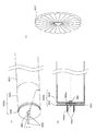
図6は、本実施例のLEDランプ照明装置のエンドキャップ部の形状の一例を示す図であって、当該エンドキャップ部が、互いに独立して回動可能に取り付けられている二つの部材から構成されていることを示したものである。このうち、図6(a)は、かかるエンドキャップ部の斜視図であって、一対のエンドキャップ部のうちの一方のエンドキャップ部0620aを示したものである(他方のエンドキャップ部はこれと左右対称に現れるため図示を省略した)。この図の例では、当該エンドキャップ部0620aは、LEDランプ0610とほぼ同一の管径を有する円筒形状の部材(便宜上「円筒形状部材」と呼ぶ)0624と、当該円筒形状部材の外側(蛍光灯灯具のソケット側)に配置されるエンドキャップ部とほぼ同径の円盤形状の部材(便宜上「円盤形状部材」と呼ぶ)0625とからなる。円盤状部材の外側の面(蛍光灯灯具のソケット側の面)には本発明のLED照明装置を直管型蛍光灯灯具に取り付けるための支持ピン0622が備えられる。円筒形状部材と円盤形状部材は互いに独立して回動可能に取り付けられる。本図の例では、両部材が、それぞれの中央部分に穿たれた小孔(本図には現れない)を貫通するリベット0691(本図ではリベットの頭頂部が現れている)によって互いに独立して回動可能なように半固定されている。
FIG. 6 is a diagram showing an example of the shape of the end cap portion of the LED lamp illumination device of the present embodiment, and the end cap portion is composed of two members that are rotatably attached independently of each other. It is shown that. 6A is a perspective view of the end cap portion, and shows one
図6(b)は、図6(a)のA−A線断面図であり、円筒形状部材0625と円盤形状部材0626(ともに右上がり斜線で示す)が、それぞれの中央部分に穿たれた小孔0625a、0626aを貫通するリベット0691(左上がり斜線で示す)によって互いに独立して回動可能なように半固定されている状態を示したものである。
FIG. 6B is a cross-sectional view taken along the line AA of FIG. 6A, in which a
なお、リベットはハトメ形状のものであってもよい。また、円筒形状部材と円盤形状部材のそれぞれの対向面のうち一方に雄ねじが形成され、他方に雌ねじが形成されて、これらが人の手で容易に回動させることができる程度に緩やかに嵌合させられているものであってもよい。さらに、円筒形状部材と円盤形状部材の取り付け部分の構造はこれらに限られることなく、要するに、両部材が互いに脱落することなく、互いに容易に回動可能に取り付けられる構造であれば、どのようなものであってもよい。 Note that the rivet may be an eyelet-shaped one. In addition, a male screw is formed on one of the opposing surfaces of the cylindrical member and the disk-shaped member, and a female screw is formed on the other, so that they can be fitted gently so that they can be easily rotated by a human hand. It may be combined. Furthermore, the structure of the attachment part of the cylindrical member and the disk-shaped member is not limited to these. In short, any structure can be used as long as both members can be attached to each other so as to be easily rotatable without dropping off from each other. It may be a thing.
かかる構成によれば、LED照明装置を既設の蛍光灯灯具に設置する際に、LEDランプ部の向きをLED素子が所望の照明方向に向くように保ったまま、エンドキャップ部の円盤形状部材の向きだけを蛍光灯灯具のソケットに合わせる動作を容易に行うことができるため、LED照明装置の取付け作業を簡単に行うことができる。 According to such a configuration, when the LED lighting device is installed in an existing fluorescent lamp, the disk-shaped member of the end cap portion is maintained while keeping the LED lamp portion facing the desired illumination direction. Since it is possible to easily perform the operation of aligning only the direction with the socket of the fluorescent lamp, it is possible to easily perform the mounting operation of the LED lighting device.
さらに、図6(b)の例にも示されているように、円筒形状部材と円盤形状部材のそれぞれの対向する面に、互いにぴったりと噛み合う面を有する二つの略円盤状の部材0627を固定的に取り付けてもよい。当該部材が互いにぴったりと噛み合う面の具体的な形状としては、例えば、放射状に配置された波形形状や、円周上に配置されたディンプル形状のものなどが考えられる(図6(b)に示したものは前者の例である)。また、それぞれの部材を円筒形状部材と円盤形状部材に固定するための接着などがしやすいように、固定面(当該部材の互いに噛み合う面とは反対側の面)は平らにしてもよい。
Further, as shown in the example of FIG. 6 (b), two substantially disk-shaped
この場合、二つの略円盤状の部材の面の形状はほぼ同一の形状に形成される。このような部材を円筒形状部材と円盤形状部材のそれぞれに固定的に取り付けることにより、円筒形状部材と円盤形状部材が、単に互いに独立して回動可能となるだけでなく、蛍光灯灯具に取り付けた状態でエンドキャップ部の円筒形状部材およびこれに固定されたLEDランプ部を回動させて任意の位置(角度)に保つことが可能となる。 In this case, the shapes of the surfaces of the two substantially disk-shaped members are formed in substantially the same shape. By fixing such a member to each of the cylindrical member and the disk-shaped member, the cylindrical member and the disk-shaped member are not only rotatable independently of each other, but also attached to a fluorescent lamp. In this state, the cylindrical member of the end cap part and the LED lamp part fixed thereto can be rotated and kept at an arbitrary position (angle).
かかる構成によれば、LEDランプ部に配置されているLED素子を任意の方向にむけることが可能となる。即ち、LED素子は発光の方向にある程度の指向性を有している。このLED素子は、例えば、二列のアレイを形成するように配置され、それぞれのアレイは垂直軸を挟んで斜め外側の方向(例えば45度の方向)に向けて発光するように配置される。そうするとLEDランプの真下部分はLED素子からの光が直接向けられず、相対的に暗い状態となる。そこで、上記構成を利用してLEDランプを回動させて、一方のアレイが真下方向を照らすような位置に保てば、真下を明るく照らすことが可能となる。この例のように、LED素子が任意の方向に向くようにLEDランプを回動させることで、部屋の任意の方向を明るく照らすことが可能となる。 According to such a configuration, the LED element disposed in the LED lamp portion can be directed in an arbitrary direction. That is, the LED element has a certain degree of directivity in the direction of light emission. The LED elements are arranged so as to form, for example, a two-row array, and each array is arranged so as to emit light toward a diagonally outer direction (for example, a 45 degree direction) across the vertical axis. If it does so, the light from an LED element will not be directed directly but the part just under an LED lamp will be in a relatively dark state. Therefore, if the LED lamp is rotated using the above configuration and is kept at a position where one of the arrays illuminates directly below, it becomes possible to illuminate directly below. As in this example, it is possible to brightly illuminate any direction of the room by rotating the LED lamp so that the LED elements are oriented in any direction.
図6(c)は、略円盤状の部材0627の形状の一例であって、図6(b)の例と同様の放射状に配置された点対称の波形形状の一例を示したものである。本図に示す部材も、固定面(本図には現れない)は平らに形成されている例である。本図の例では、24個の波形が形成されているため、円筒形状部材側に固定された当該部材を回動させながら15度ごとの任意の角度で、円盤形状部材側の部材にぴったりと噛み合わせつつ固定することが可能となっている。このため、すべての波形が等角度でかつ同一の形状であることが望ましい。
FIG. 6C shows an example of the shape of the substantially disk-shaped
<効果> <Effect>
本実施例の発明により、LED照明装置を既設の蛍光灯灯具に設置する際に、LEDランプ部の向きをLED素子が所望の照明方向に向くように保ったまま、エンドキャップ部の円盤形状部材の向きだけを蛍光灯灯具のソケットに合わせる動作を容易に行うことができるため、LED照明装置の取付け作業を簡単に行うことが可能となる。 According to the invention of the present embodiment, when the LED lighting device is installed in an existing fluorescent lamp, the disk-shaped member of the end cap portion is maintained while keeping the LED lamp portion facing the desired illumination direction. Therefore, it is possible to easily attach the LED lighting device to the socket of the fluorescent lamp.
Claims (4)
前記LEDランプ部の両端にそれぞれ備えられ、直管型蛍光灯灯具のソケットに取り付け可能な支持ピンを備えた一対のエンドキャップ部と、
電源からの電力線に接続された電源コネクターを接続可能な本体コネクター部と、
を有するLED照明装置と、
電源からの電力線に接続され、前記LED照明装置の本体コネクター部に接続可能な電源コネクターを有する直管型蛍光灯灯具と、
を有するLED照明システム。 An LED lamp part having a straight tube fluorescent lamp shape and having a plurality of LED elements disposed thereon;
A pair of end cap parts each provided with a support pin that can be attached to both ends of the LED lamp part and can be attached to a socket of a straight tube fluorescent lamp,
A body connector that can be connected to a power connector connected to the power line from the power source,
An LED lighting device having,
A straight tube fluorescent lamp having a power connector connected to a power line from a power source and connectable to a main body connector portion of the LED lighting device;
LED lighting system .
Priority Applications (1)
| Application Number | Priority Date | Filing Date | Title |
|---|---|---|---|
| JP2012049385A JP5187792B2 (en) | 2012-03-06 | 2012-03-06 | LED lighting device |
Applications Claiming Priority (1)
| Application Number | Priority Date | Filing Date | Title |
|---|---|---|---|
| JP2012049385A JP5187792B2 (en) | 2012-03-06 | 2012-03-06 | LED lighting device |
Related Parent Applications (1)
| Application Number | Title | Priority Date | Filing Date |
|---|---|---|---|
| JP2009259312A Division JP4986303B2 (en) | 2009-11-12 | 2009-11-12 | LED lighting device |
Related Child Applications (4)
| Application Number | Title | Priority Date | Filing Date |
|---|---|---|---|
| JP2012167836A Division JP5187794B2 (en) | 2012-07-28 | 2012-07-28 | LED lighting device |
| JP2012167838A Division JP5187796B2 (en) | 2012-07-28 | 2012-07-28 | LED lighting device |
| JP2012167835A Division JP5187793B2 (en) | 2012-07-28 | 2012-07-28 | LED lighting device |
| JP2012167837A Division JP5187795B2 (en) | 2012-07-28 | 2012-07-28 | LED lighting device |
Publications (3)
| Publication Number | Publication Date |
|---|---|
| JP2012109277A JP2012109277A (en) | 2012-06-07 |
| JP2012109277A5 JP2012109277A5 (en) | 2012-09-13 |
| JP5187792B2 true JP5187792B2 (en) | 2013-04-24 |
Family
ID=46494614
Family Applications (1)
| Application Number | Title | Priority Date | Filing Date |
|---|---|---|---|
| JP2012049385A Active JP5187792B2 (en) | 2012-03-06 | 2012-03-06 | LED lighting device |
Country Status (1)
| Country | Link |
|---|---|
| JP (1) | JP5187792B2 (en) |
Families Citing this family (2)
| Publication number | Priority date | Publication date | Assignee | Title |
|---|---|---|---|---|
| CN102900981B (en) * | 2012-09-29 | 2015-09-02 | 宁波同泰电气股份有限公司 | The two-sided fluorescent lamp of rotatable LED of power supply external |
| CN105042420B (en) * | 2015-07-29 | 2017-07-21 | 苏州东亚欣业节能照明有限公司 | LED pipe plug and LED lamp tube |
Family Cites Families (2)
| Publication number | Priority date | Publication date | Assignee | Title |
|---|---|---|---|---|
| JP5142620B2 (en) * | 2007-08-06 | 2013-02-13 | シャープ株式会社 | Lighting device |
| JP3153538U (en) * | 2009-06-26 | 2009-09-10 | 株式会社鈴三物流 | LED fluorescent lamp |
-
2012
- 2012-03-06 JP JP2012049385A patent/JP5187792B2/en active Active
Also Published As
| Publication number | Publication date |
|---|---|
| JP2012109277A (en) | 2012-06-07 |
Similar Documents
| Publication | Publication Date | Title |
|---|---|---|
| JP4986303B2 (en) | LED lighting device | |
| JP3154671U (en) | LED lamp | |
| US8500303B2 (en) | LED lamp | |
| US9395052B1 (en) | Modular lighting assembly | |
| JP3154200U (en) | LED lamp | |
| JP3152509U (en) | LED straight tube lamp structure | |
| JP2011113663A (en) | Fluorescent lamp type led lighting tube | |
| JP5187792B2 (en) | LED lighting device | |
| JP5636606B2 (en) | LED lighting device | |
| JP5187795B2 (en) | LED lighting device | |
| TW201432192A (en) | Lighting module, straight tube lamp, and lighting apparatus | |
| JP5187793B2 (en) | LED lighting device | |
| JP5187794B2 (en) | LED lighting device | |
| JP5187796B2 (en) | LED lighting device | |
| JP2011108376A (en) | Light source and lighting fixture | |
| JP2014135284A (en) | Led lighting apparatus | |
| JP2011146129A (en) | Adapter lamp fixture for attaching variant fluorescent lamp to straight-tube fluorescent lamp fixture | |
| JP2012174362A (en) | Led lighting fixture | |
| JP6279333B2 (en) | Lighting unit | |
| JP6008270B2 (en) | Emergency lighting equipment | |
| JP6754413B2 (en) | Connecting member | |
| JP2013127917A (en) | Emergency lighting fixture | |
| JP2012185951A (en) | Lamp and lighting system using the same | |
| JP3183416U (en) | Straight tube type LED lamp and power supply device for straight tube type LED lamp | |
| JP2007080803A (en) | Power saving type fluorescent lamp fixture |
Legal Events
| Date | Code | Title | Description |
|---|---|---|---|
| A521 | Request for written amendment filed |
Free format text: JAPANESE INTERMEDIATE CODE: A523 Effective date: 20120728 |
|
| A621 | Written request for application examination |
Free format text: JAPANESE INTERMEDIATE CODE: A621 Effective date: 20120728 |
|
| A871 | Explanation of circumstances concerning accelerated examination |
Free format text: JAPANESE INTERMEDIATE CODE: A871 Effective date: 20121010 |
|
| A975 | Report on accelerated examination |
Free format text: JAPANESE INTERMEDIATE CODE: A971005 Effective date: 20121026 |
|
| TRDD | Decision of grant or rejection written | ||
| A01 | Written decision to grant a patent or to grant a registration (utility model) |
Free format text: JAPANESE INTERMEDIATE CODE: A01 Effective date: 20121218 |
|
| A61 | First payment of annual fees (during grant procedure) |
Free format text: JAPANESE INTERMEDIATE CODE: A61 Effective date: 20130116 |
|
| FPAY | Renewal fee payment (event date is renewal date of database) |
Free format text: PAYMENT UNTIL: 20160201 Year of fee payment: 3 |
|
| R150 | Certificate of patent or registration of utility model |
Ref document number: 5187792 Country of ref document: JP Free format text: JAPANESE INTERMEDIATE CODE: R150 Free format text: JAPANESE INTERMEDIATE CODE: R150 |
|
| S111 | Request for change of ownership or part of ownership |
Free format text: JAPANESE INTERMEDIATE CODE: R313117 |
|
| R350 | Written notification of registration of transfer |
Free format text: JAPANESE INTERMEDIATE CODE: R350 |
|
| R250 | Receipt of annual fees |
Free format text: JAPANESE INTERMEDIATE CODE: R250 |
|
| R250 | Receipt of annual fees |
Free format text: JAPANESE INTERMEDIATE CODE: R250 |
|
| R250 | Receipt of annual fees |
Free format text: JAPANESE INTERMEDIATE CODE: R250 |
|
| R250 | Receipt of annual fees |
Free format text: JAPANESE INTERMEDIATE CODE: R250 |
|
| R250 | Receipt of annual fees |
Free format text: JAPANESE INTERMEDIATE CODE: R250 |
|
| S531 | Written request for registration of change of domicile |
Free format text: JAPANESE INTERMEDIATE CODE: R313531 |
|
| R350 | Written notification of registration of transfer |
Free format text: JAPANESE INTERMEDIATE CODE: R350 |
|
| R250 | Receipt of annual fees |
Free format text: JAPANESE INTERMEDIATE CODE: R250 |
|
| R250 | Receipt of annual fees |
Free format text: JAPANESE INTERMEDIATE CODE: R250 |
|
| R250 | Receipt of annual fees |
Free format text: JAPANESE INTERMEDIATE CODE: R250 |