JP5186246B2 - Operation unit of disposable treatment instrument for endoscope - Google Patents
Operation unit of disposable treatment instrument for endoscope Download PDFInfo
- Publication number
- JP5186246B2 JP5186246B2 JP2008051820A JP2008051820A JP5186246B2 JP 5186246 B2 JP5186246 B2 JP 5186246B2 JP 2008051820 A JP2008051820 A JP 2008051820A JP 2008051820 A JP2008051820 A JP 2008051820A JP 5186246 B2 JP5186246 B2 JP 5186246B2
- Authority
- JP
- Japan
- Prior art keywords
- wire
- slit
- slide operation
- hole
- attachment member
- Prior art date
- Legal status (The legal status is an assumption and is not a legal conclusion. Google has not performed a legal analysis and makes no representation as to the accuracy of the status listed.)
- Expired - Fee Related
Links
Images


Landscapes
- Surgical Instruments (AREA)
- Endoscopes (AREA)
Description
この発明は、内視鏡の処置具挿通チャンネルに通して使用される内視鏡用ディスポーザブル処置具の操作部に関する。 The present invention relates to an operation unit of an endoscope disposable treatment instrument used through a treatment instrument insertion channel of an endoscope.
内視鏡用処置具として、操作ワイヤが軸線方向に可動に挿通配置されたシース部と、その操作ワイヤを進退操作するためのスライド操作部材が配置された操作部とを備え、そのようなシース部と操作部とを一まとめに使い捨て式にしたディスポーザブル処置具がある。 As a treatment instrument for an endoscope, a sheath portion in which an operation wire is movably inserted and arranged in the axial direction and an operation portion in which a slide operation member for advancing and retracting the operation wire is arranged are provided. There is a disposable treatment tool in which the operation part and the operation part are made into a single-use type.
ただし、部品の共通化によるコストダウンを図るため、操作ワイヤの必要最大ストロークが相違する複数機種に同じ操作部を使用して出荷する場合には、操作ワイヤの必要最大ストロークの相違に対応してスライド操作部材の最大可動距離を設定しておく必要がある。 However, in order to reduce costs by standardizing parts, when shipping using the same operation unit for multiple models with different required maximum strokes of the operation wire, it is necessary to respond to differences in the required maximum stroke of the operation wire. It is necessary to set the maximum movable distance of the slide operation member.
最大可動距離が不足すると処置具の機能が発揮できず、最大可動距離が過多の場合は、シース部の先端から処置部材が飛び出しすぎて、処置部材やシース部等が破損したり座屈したりする恐れがある。 If the maximum movable distance is insufficient, the function of the treatment tool cannot be exerted. If the maximum movable distance is excessive, the treatment member jumps out from the distal end of the sheath part, and the treatment member or the sheath part is damaged or buckled. There is a fear.
そこで従来は、操作部本体に設けられた可撓性チューブ製のストッパを適宜の長さに切断することにより、スライド操作部材の最大可動距離を任意に設定することができるようにしていた(例えば、特許文献1)。
しかし、可撓性チューブ製のストッパは、使用中に想定以上の強い力で押されると潰れてしまって操作ワイヤのストロークが過大になったり操作不良になる恐れがある。また、ストッパを誤って所定より短く切断してしまうと操作部全体が使い物にならなくなってしまう場合がある。 However, if the stopper made of a flexible tube is pressed with a stronger force than expected during use, the stopper may be crushed, resulting in an excessive stroke of the operation wire or poor operation. Further, if the stopper is accidentally cut shorter than a predetermined length, the entire operation unit may not be usable.
本発明は、操作ワイヤの必要最大ストロークが相違する複数機種に同じ操作部を使用する場合に、その各々に適合した最大ストロークになるように容易にセッティングして、良好な状態で使用することができる内視鏡用ディスポーザブル処置具の操作部を提供することを目的とする。 When using the same operation unit for multiple models with different required maximum strokes of the operation wire, the present invention can be easily set to the maximum stroke suitable for each and used in good condition. An object of the present invention is to provide an operation unit for a disposable treatment instrument for an endoscope.
上記の目的を達成するため、本発明の内視鏡用ディスポーザブル処置具の操作部は、操作部本体に前後方向に細長く形成されたスリット内において操作ワイヤの基端が連結されたワイヤ取付部材に、スリット外に突出した形状のスライド操作部材が取り付けられ、ワイヤ取付部材をスライド操作部材でスリットの長手方向に沿って移動させることにより、操作ワイヤが軸線方向に進退操作されるように構成された内視鏡用ディスポーザブル処置具の操作部において、ワイヤ取付部材に対するスライド操作部材の取り付け位置を、スリットの長手方向において相違する複数箇所の中から任意に選択することができる取付位置選択手段を設けて、ワイヤ取付部材に対するスライド操作部材の取り付け位置を選択することによりスリット内におけるワイヤ取付部材の最大可動距離を設定することができるようにすると共に、ワイヤ取付部材に対するスライド操作部材の取り付け位置が選択された状態でワイヤ取付部材に対するスライド操作部材の取り付け位置を固定する固定手段を設けたものである。 In order to achieve the above object, the operation part of the disposable treatment instrument for endoscope according to the present invention is a wire mounting member in which the base end of the operation wire is connected in a slit formed in the operation part body in the longitudinal direction. The slide operation member projecting out of the slit is attached, and the operation wire is moved back and forth in the axial direction by moving the wire attachment member along the longitudinal direction of the slit with the slide operation member. In the operation portion of the disposable treatment instrument for endoscope, there is provided an attachment position selection means capable of arbitrarily selecting the attachment position of the slide operation member with respect to the wire attachment member from a plurality of places different in the longitudinal direction of the slit. In the slit by selecting the mounting position of the slide operation member relative to the wire mounting member A fixing means for setting the maximum movable distance of the ear attachment member and fixing the attachment position of the slide operation member to the wire attachment member in a state where the attachment position of the slide operation member to the wire attachment member is selected. It is provided.
なお、スライド操作部材とワイヤ取付部材の一方には、スリット内に緩く嵌め込まれてスリットの長手方向に沿って複数の孔が形成された内挿部が備えられて、他方には内挿部と操作部本体とに緩く被嵌されて複数の孔の一つに重なり合う位置に透孔が形成された筒状部が備えられると共に、透孔と孔とにまたがって係合する連結ピンが設けられて、これらにより取付位置選択手段が形成されていてもよい。 One of the slide operation member and the wire attachment member is provided with an insertion portion loosely fitted in the slit and formed with a plurality of holes along the longitudinal direction of the slit, and the other includes an insertion portion and A cylindrical portion is provided that is loosely fitted to the operation portion main body and has a through-hole formed at a position overlapping one of the plurality of holes, and a connecting pin that engages the through-hole and the hole is provided. Thus, the attachment position selection means may be formed by these.
或いは、ワイヤ取付部材とスライド操作部材の一方には、操作部本体に緩く被嵌されてスリットの長手方向に沿って複数の透孔が形成された筒状部が備えられて、他方には筒状部の内側に位置するようにスリット内に緩く嵌め込まれて複数の透孔の一つと重なる位置に孔が形成された内挿部が備えられると共に、透孔と孔とにまたがって係合する連結ピンが設けられて、これらにより取付位置選択手段が形成されていてもよい。 Alternatively, one of the wire attachment member and the slide operation member is provided with a cylindrical portion that is loosely fitted to the operation portion main body and has a plurality of through holes formed along the longitudinal direction of the slit, and the other is a cylinder. An insertion portion is provided which is loosely fitted into the slit so as to be located inside the slit and has a hole formed at a position overlapping with one of the plurality of through holes, and is engaged across the through hole and the hole. A connection pin may be provided, and the attachment position selection means may be formed by these.
また、固定手段が、連結ピンを透孔と孔とにまたがって係合した状態で固定するものであってもよく、その固定手段が接着剤であってもよい。 Further, the fixing means may fix the connecting pin in a state of being engaged across the through hole and the hole, and the fixing means may be an adhesive.
本発明によれば、ワイヤ取付部材に対するスライド操作部材の取り付け位置を複数箇所の中から任意に選択してスリット内におけるワイヤ取付部材の最大可動距離を設定・固定することができるので、操作ワイヤの必要最大ストロークが相違する複数機種に同じ操作部を使用する場合に、その各々に適合した最大ストロークになるように容易にセッティングして、良好な状態で使用することができる。 According to the present invention, it is possible to set and fix the maximum movable distance of the wire attachment member in the slit by arbitrarily selecting the attachment position of the slide operation member with respect to the wire attachment member from among a plurality of locations. When the same operation unit is used for a plurality of models having different required maximum strokes, it can be easily set to have a maximum stroke suitable for each and used in a good condition.
操作部本体に前後方向に細長く形成されたスリット内において操作ワイヤの基端が連結されたワイヤ取付部材に、スリット外に突出した形状のスライド操作部材が取り付けられ、ワイヤ取付部材をスライド操作部材でスリットの長手方向に沿って移動させることにより、操作ワイヤが軸線方向に進退操作されるように構成された内視鏡用ディスポーザブル処置具の操作部において、ワイヤ取付部材に対するスライド操作部材の取り付け位置を、スリットの長手方向において相違する複数箇所の中から任意に選択することができる取付位置選択手段を設けて、ワイヤ取付部材に対するスライド操作部材の取り付け位置を選択することによりスリット内におけるワイヤ取付部材の最大可動距離を設定することができるようにすると共に、ワイヤ取付部材に対するスライド操作部材の取り付け位置が選択された状態でワイヤ取付部材に対するスライド操作部材の取り付け位置を固定する固定手段を設ける。 A slide operation member that protrudes out of the slit is attached to a wire attachment member that is connected to the base end of the operation wire in a slit that is elongated in the front-rear direction on the operation unit body. By moving the operation wire along the longitudinal direction of the slit, the position of the slide operation member attached to the wire attachment member in the operation portion of the disposable treatment instrument for an endoscope configured so that the operation wire is advanced and retracted in the axial direction. An attachment position selection means that can be arbitrarily selected from a plurality of different locations in the longitudinal direction of the slit is provided, and the position of the wire attachment member in the slit is selected by selecting the attachment position of the slide operation member with respect to the wire attachment member. The maximum movable distance can be set and the wire Providing a fixing means for fixing the mounting position of the slide operation member in a state where the mounting position of the slide operation member against member is selected for the wire attachment member.
以下、図面を参照して本発明の実施例を説明する。
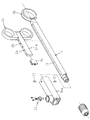
図1は内視鏡用ディスポーザブル処置具の操作部の側面断面図、図2はその分解斜視図である。
Embodiments of the present invention will be described below with reference to the drawings.
FIG. 1 is a side sectional view of an operation unit of a disposable treatment instrument for endoscope, and FIG. 2 is an exploded perspective view thereof.
図示されていない内視鏡の処置具挿通チャンネルに挿脱される可撓性シース1の基端口金2が連結された操作部本体11は、前後方向に細長い棒状に形成されて、中心軸線位置を通る前後方向に細長いスリット12により、前後両端付近の領域を除いて左右に分断された形状に形成されている。操作部本体11の後端部には、操作者の手の第1指を係合させるための固定指掛け13が設けられている。
An operation portion
可撓性シース1内に軸線方向に進退自在に全長にわたって挿通配置された操作ワイヤ3の基端部分は、可撓性シース1の基端から操作部本体11のスリット12内に引き出されていて、操作ワイヤ3の基端に固着された連結棒4が、スリット12内でワイヤ取付部材16に連結されている。
The proximal end portion of the operation wire 3 inserted through the entire length of the flexible sheath 1 so as to be movable back and forth in the axial direction is drawn from the proximal end of the flexible sheath 1 into the
22は、図示されていない高周波電源コードを接続するための接続端子であり、連結棒4が接続端子22の導電ロッドの先端でワイヤ取付部材16に押圧固定されている。その結果、接続端子22から操作ワイヤ3に高周波電流を通電することができる。
ワイヤ取付部材16には、操作部本体11に軸線方向に進退自在に緩く被嵌された筒状部16aが一体に備えられている。ただし、この実施例では、部品製造の容易性から独立して単体で形成された筒状部16aがワイヤ取付部材16にビス止め固定されてそれらが一体化されている。
The
ワイヤ取付部材16には、スリット12外に突出した形状のスライド操作部材24が取り付けられている。スライド操作部材24には、操作者の第2指と第3指を係合させるための二つのリングが形成されており、ワイヤ取付部材16をスライド操作部材24で操作部本体11の長手方向(即ち、スリット12の長手方向)に沿って移動させることにより、操作ワイヤ3が軸線方向に進退操作される。
A
スライド操作部材24には、スリット12の内側に緩く嵌め込まれてスリット12の長手方向に沿って各々が同じ径の複数の孔25(ここでは5個の孔)が一定の深さに一定の間隔で形成された内挿部24aが備えられている。この実施例では、そのような孔25の列が180°対称位置(裏と表)に設けられている。
A plurality of holes 25 (here, five holes) having the same diameter along the longitudinal direction of the
一方、ワイヤ取付部材16には、スライド操作部材24の内挿部24aと操作部本体11とにまたがって緩く被嵌されて、スライド操作部材24の孔25の一つに重なり合う位置に透孔17が形成された筒状部16aが備えられている。なお、透孔17が複数設けられていても差し支えない。
On the other hand, the
そして、ワイヤ取付部材16の透孔17とスライド操作部材24の孔25とにまたがって真っ直ぐに差し込まれた状態に係合する硬質の連結ピン27が設けられており、スライド操作部材24の内挿部24aに対してワイヤ取付部材16の筒状部16aをスライドさせることにより、スライド操作部材24の任意の孔25とワイヤ取付部材16の透孔17とにまたがって連結ピン27を係合させることができる。
A hard connecting
このようにして、ワイヤ取付部材16に対するスライド操作部材24の取り付け位置を、スリット12の長手方向において相違する複数箇所の中から任意に選択することができる「取付位置選択手段」が構成されている。
In this way, “attachment position selection means” is configured that can arbitrarily select the attachment position of the
また、連結ピン27は、透孔17と孔25とにまたがって係合した状態で接着剤28(固定手段)により固定されており、連結ピン27が係合する孔25を選択してワイヤ取付部材16に対するスライド操作部材24の取り付け位置が選択された状態で、ワイヤ取付部材16に対するスライド操作部材24の取り付け位置が固定される。なお、そのための固定手段が接着剤28以外のもの(例えば、ねじ等)であっても差し支えない。
Further, the connecting
このようにして、ワイヤ取付部材16に対するスライド操作部材24の取り付け位置を、スリット12の長手方向において相違する複数箇所の中から任意に選択すると、スライド操作部材24の最大可動距離(即ち、操作ワイヤ3の最大ストローク)は、ワイヤ取付部材16とスライド操作部材24の合計長とスリット12の長さとの差に略等しい。
In this manner, when the attachment position of the
その結果、図3及び図4に例示されるように、ワイヤ取付部材16に対するスライド操作部材24の取り付け位置を変えることにより、スリット12内におけるワイヤ取付部材16の最大可動距離L1,L2をその機種に合わせて設定し、その状態を固定して出荷することができる。
As a result, as illustrated in FIGS. 3 and 4, the maximum movable distances L <b> 1 and L <b> 2 of the
図5は本発明の第2の実施例の内視鏡用ディスポーザブル処置具の操作部を示しており、ワイヤ取付部材16の筒状部16a側に複数の透孔17を形成して、スライド操作部材24の内挿部24a側には、その複数の透孔17の一つと重なる位置に孔を形成したものである。その他の構成は前述の第1の実施例と同じである。このように構成しても第1の実施例と同様の作用効果が得られる。
FIG. 5 shows the operation part of the disposable treatment instrument for endoscope according to the second embodiment of the present invention, in which a plurality of through
また、上記の各実施例において、筒状部16aをワイヤ取付部材16と一体ではなくスライド操作部材24と一体に形成して、内挿部24aをスライド操作部材24と一体ではなくワイヤ取付部材16と一体に形成した構成を採っても差し支えない。
Further, in each of the above-described embodiments, the
1 可撓性シース
3 操作ワイヤ
11 操作部本体
12 スリット
16 ワイヤ取付部材
16a 筒状部
17 透孔(取付位置選択手段)
24 スライド操作部材
24a 内挿部
25 孔(取付位置選択手段)
27 連結ピン(取付位置選択手段)
28 接着剤(固定手段)
DESCRIPTION OF SYMBOLS 1 Flexible sheath 3
24
27 Connecting pin (Mounting position selection means)
28 Adhesive (fixing means)
Claims (4)
上記ワイヤ取付部材に対する上記スライド操作部材の取り付け位置を、上記スリットの長手方向において相違する複数箇所の中から任意に選択することができる取付位置選択手段を設けて、上記ワイヤ取付部材に対する上記スライド操作部材の取り付け位置を選択することにより上記スリット内における上記ワイヤ取付部材の最大可動距離を設定することができるようにすると共に、
上記ワイヤ取付部材に対する上記スライド操作部材の取り付け位置が選択された状態で上記ワイヤ取付部材に対する上記スライド操作部材の取り付け位置を固定する固定手段を設け、
上記スライド操作部材と上記ワイヤ取付部材の一方には、上記スリット内に緩く嵌め込まれて上記スリットの長手方向に沿って複数の孔が形成された内挿部が備えられて、他方には上記内挿部と上記操作部本体とに緩く被嵌されて上記複数の孔の一つに重なり合う位置に透孔が形成された筒状部が備えられると共に、上記透孔と上記孔とにまたがって係合する連結ピンが設けられて、これらにより上記取付位置選択手段が形成されている内視鏡用ディスポーザブル処置具の操作部。 A slide operation member having a shape protruding out of the slit is attached to a wire attachment member to which the proximal end of the operation wire is coupled in a slit formed in the front and rear direction of the operation unit main body, and the wire attachment member is slid In the operation part of the disposable treatment instrument for endoscope configured such that the operation wire is moved forward and backward in the axial direction by moving the operation member along the longitudinal direction of the slit,
The slide operation on the wire attachment member is provided by providing attachment position selection means capable of arbitrarily selecting the attachment position of the slide operation member relative to the wire attachment member from a plurality of places different in the longitudinal direction of the slit. By selecting the attachment position of the member, the maximum movable distance of the wire attachment member in the slit can be set, and
A fixing means for fixing the mounting position of the slide operation member with respect to the wire mounting member in a state where the mounting position of the slide operation member with respect to the wire mounting member is selected;
One of the slide operation member and the wire attachment member is provided with an insertion portion that is loosely fitted into the slit and formed with a plurality of holes along the longitudinal direction of the slit, and the other is provided with the inner portion. A cylindrical portion that is loosely fitted to the insertion portion and the operation portion main body and has a through-hole formed at a position overlapping one of the plurality of holes is provided, and the tubular portion extends across the through-hole and the hole. The operation part of the disposable treatment tool for endoscopes, in which connecting pins to be combined are provided, and the attachment position selection means is formed by these connecting pins.
上記ワイヤ取付部材に対する上記スライド操作部材の取り付け位置を、上記スリットの長手方向において相違する複数箇所の中から任意に選択することができる取付位置選択手段を設けて、上記ワイヤ取付部材に対する上記スライド操作部材の取り付け位置を選択することにより上記スリット内における上記ワイヤ取付部材の最大可動距離を設定することができるようにすると共に、
上記ワイヤ取付部材に対する上記スライド操作部材の取り付け位置が選択された状態で上記ワイヤ取付部材に対する上記スライド操作部材の取り付け位置を固定する固定手段を設け、
上記ワイヤ取付部材と上記スライド操作部材の一方には、上記操作部本体に緩く被嵌されて上記スリットの長手方向に沿って複数の透孔が形成された筒状部が備えられて、他方には上記筒状部の内側に位置するように上記スリット内に緩く嵌め込まれて上記複数の透孔の一つと重なる位置に孔が形成された内挿部が備えられると共に、上記透孔と上記孔とにまたがって係合する連結ピンが設けられて、これらにより上記取付位置選択手段が形成されている内視鏡用ディスポーザブル処置具の操作部。 A slide operation member having a shape protruding out of the slit is attached to a wire attachment member to which the proximal end of the operation wire is coupled in a slit formed in the front and rear direction of the operation unit main body, and the wire attachment member is slid In the operation part of the disposable treatment instrument for endoscope configured such that the operation wire is moved forward and backward in the axial direction by moving the operation member along the longitudinal direction of the slit,
The slide operation on the wire attachment member is provided by providing attachment position selection means capable of arbitrarily selecting the attachment position of the slide operation member relative to the wire attachment member from a plurality of places different in the longitudinal direction of the slit. By selecting the attachment position of the member, the maximum movable distance of the wire attachment member in the slit can be set, and
A fixing means for fixing the mounting position of the slide operation member with respect to the wire mounting member in a state where the mounting position of the slide operation member with respect to the wire mounting member is selected;
One of the wire attachment member and the slide operation member is provided with a cylindrical portion that is loosely fitted to the operation portion main body and has a plurality of through holes formed along the longitudinal direction of the slit. Is provided with an insertion portion that is loosely fitted into the slit so as to be located inside the cylindrical portion and has a hole formed at a position overlapping one of the plurality of through holes, and the through hole and the hole. An operation portion of the disposable treatment instrument for an endoscope, in which a connecting pin that is engaged with each other is provided, and the attachment position selection means is formed by these connecting pins.
Priority Applications (1)
| Application Number | Priority Date | Filing Date | Title |
|---|---|---|---|
| JP2008051820A JP5186246B2 (en) | 2008-03-03 | 2008-03-03 | Operation unit of disposable treatment instrument for endoscope |
Applications Claiming Priority (1)
| Application Number | Priority Date | Filing Date | Title |
|---|---|---|---|
| JP2008051820A JP5186246B2 (en) | 2008-03-03 | 2008-03-03 | Operation unit of disposable treatment instrument for endoscope |
Publications (2)
| Publication Number | Publication Date |
|---|---|
| JP2009207591A JP2009207591A (en) | 2009-09-17 |
| JP5186246B2 true JP5186246B2 (en) | 2013-04-17 |
Family
ID=41181345
Family Applications (1)
| Application Number | Title | Priority Date | Filing Date |
|---|---|---|---|
| JP2008051820A Expired - Fee Related JP5186246B2 (en) | 2008-03-03 | 2008-03-03 | Operation unit of disposable treatment instrument for endoscope |
Country Status (1)
| Country | Link |
|---|---|
| JP (1) | JP5186246B2 (en) |
Families Citing this family (1)
| Publication number | Priority date | Publication date | Assignee | Title |
|---|---|---|---|---|
| JP6454563B2 (en) * | 2015-02-12 | 2019-01-16 | 株式会社トップ | Surgical instrument aids |
Family Cites Families (8)
| Publication number | Priority date | Publication date | Assignee | Title |
|---|---|---|---|---|
| JP3936031B2 (en) * | 1997-07-16 | 2007-06-27 | ペンタックス株式会社 | Endoscopic endoscope treatment tool |
| JP3922667B2 (en) * | 1998-05-06 | 2007-05-30 | 株式会社貝印刃物開発センター | Operating device for treatment tool for endoscope |
| JP3370601B2 (en) * | 1998-05-28 | 2003-01-27 | ペンタックス株式会社 | Operation unit of endoscope treatment tool |
| JP3634644B2 (en) * | 1998-10-29 | 2005-03-30 | ペンタックス株式会社 | Endoscope operation part |
| JP4291056B2 (en) * | 2003-06-25 | 2009-07-08 | 有限会社リバー精工 | Endoscopic treatment tool |
| JP2005218683A (en) * | 2004-02-06 | 2005-08-18 | Pentax Corp | Operation part of holding forceps for endoscope |
| JP2006068076A (en) * | 2004-08-31 | 2006-03-16 | Olympus Corp | Treatment instrument for endoscope |
| JP4512724B2 (en) * | 2006-03-16 | 2010-07-28 | 有限会社リバー精工 | Endoscopic treatment tool |
-
2008
- 2008-03-03 JP JP2008051820A patent/JP5186246B2/en not_active Expired - Fee Related
Also Published As
| Publication number | Publication date |
|---|---|
| JP2009207591A (en) | 2009-09-17 |
Similar Documents
| Publication | Publication Date | Title |
|---|---|---|
| US7922717B2 (en) | High-frequency treatment tool for endoscope | |
| JP3917332B2 (en) | Endoscope operation wire connecting part | |
| JP5022841B2 (en) | Endoscopic high-frequency treatment instrument | |
| JP4731274B2 (en) | Endoscopic high-frequency incision tool | |
| JP4895509B2 (en) | Endoscopic treatment tool | |
| JP2009268763A (en) | Operation section of treatment instrument for endoscope | |
| JP4598197B2 (en) | Endoscopic treatment tool | |
| US8052682B2 (en) | High-frequency incision instrument for endoscope | |
| JP4589731B2 (en) | Endoscopic high-frequency treatment instrument | |
| JP5186246B2 (en) | Operation unit of disposable treatment instrument for endoscope | |
| JP5114333B2 (en) | Endoscopic treatment tool | |
| JP4475991B2 (en) | Endoscopic high-frequency incision tool | |
| JP5191364B2 (en) | Endoscopic treatment tool | |
| JP4481957B2 (en) | Endoscopic treatment tool | |
| JP5244418B2 (en) | Endoscope operation part | |
| JP2012050758A (en) | Hook-like high-frequency knife for flexible endoscope | |
| JPWO2021100079A5 (en) | ||
| JP4575709B2 (en) | Endoscopic high-frequency treatment instrument | |
| JP4611772B2 (en) | Endoscopic treatment tool | |
| JP4753261B2 (en) | Operation part of high-frequency treatment instrument for endoscope | |
| JP4495493B2 (en) | Endoscopic high-frequency incision tool | |
| JP5191365B2 (en) | Endoscopic high-frequency treatment instrument | |
| JP5235709B2 (en) | Endoscopic high-frequency treatment instrument | |
| JP5952068B2 (en) | Endoscopic high-frequency treatment instrument | |
| JP2005198931A (en) | Snare for endoscope |
Legal Events
| Date | Code | Title | Description |
|---|---|---|---|
| A621 | Written request for application examination |
Free format text: JAPANESE INTERMEDIATE CODE: A621 Effective date: 20101125 |
|
| RD02 | Notification of acceptance of power of attorney |
Free format text: JAPANESE INTERMEDIATE CODE: A7422 Effective date: 20120719 |
|
| RD04 | Notification of resignation of power of attorney |
Free format text: JAPANESE INTERMEDIATE CODE: A7424 Effective date: 20120727 |
|
| A131 | Notification of reasons for refusal |
Free format text: JAPANESE INTERMEDIATE CODE: A131 Effective date: 20120830 |
|
| A521 | Written amendment |
Free format text: JAPANESE INTERMEDIATE CODE: A523 Effective date: 20121002 |
|
| TRDD | Decision of grant or rejection written | ||
| A01 | Written decision to grant a patent or to grant a registration (utility model) |
Free format text: JAPANESE INTERMEDIATE CODE: A01 Effective date: 20130110 |
|
| A61 | First payment of annual fees (during grant procedure) |
Free format text: JAPANESE INTERMEDIATE CODE: A61 Effective date: 20130121 |
|
| R150 | Certificate of patent or registration of utility model |
Free format text: JAPANESE INTERMEDIATE CODE: R150 |
|
| FPAY | Renewal fee payment (event date is renewal date of database) |
Free format text: PAYMENT UNTIL: 20160125 Year of fee payment: 3 |
|
| S531 | Written request for registration of change of domicile |
Free format text: JAPANESE INTERMEDIATE CODE: R313531 |
|
| R350 | Written notification of registration of transfer |
Free format text: JAPANESE INTERMEDIATE CODE: R350 |
|
| R250 | Receipt of annual fees |
Free format text: JAPANESE INTERMEDIATE CODE: R250 |
|
| LAPS | Cancellation because of no payment of annual fees |