JP5183181B2 - Inkjet recording head - Google Patents
Inkjet recording head Download PDFInfo
- Publication number
- JP5183181B2 JP5183181B2 JP2007320143A JP2007320143A JP5183181B2 JP 5183181 B2 JP5183181 B2 JP 5183181B2 JP 2007320143 A JP2007320143 A JP 2007320143A JP 2007320143 A JP2007320143 A JP 2007320143A JP 5183181 B2 JP5183181 B2 JP 5183181B2
- Authority
- JP
- Japan
- Prior art keywords
- ink
- ink flow
- flow path
- recording head
- flow resistance
- Prior art date
- Legal status (The legal status is an assumption and is not a legal conclusion. Google has not performed a legal analysis and makes no representation as to the accuracy of the status listed.)
- Expired - Fee Related
Links
Images


Classifications
-
- B—PERFORMING OPERATIONS; TRANSPORTING
- B41—PRINTING; LINING MACHINES; TYPEWRITERS; STAMPS
- B41J—TYPEWRITERS; SELECTIVE PRINTING MECHANISMS, i.e. MECHANISMS PRINTING OTHERWISE THAN FROM A FORME; CORRECTION OF TYPOGRAPHICAL ERRORS
- B41J2/00—Typewriters or selective printing mechanisms characterised by the printing or marking process for which they are designed
- B41J2/005—Typewriters or selective printing mechanisms characterised by the printing or marking process for which they are designed characterised by bringing liquid or particles selectively into contact with a printing material
- B41J2/01—Ink jet
- B41J2/135—Nozzles
- B41J2/14—Structure thereof only for on-demand ink jet heads
- B41J2/1433—Structure of nozzle plates
-
- B—PERFORMING OPERATIONS; TRANSPORTING
- B41—PRINTING; LINING MACHINES; TYPEWRITERS; STAMPS
- B41J—TYPEWRITERS; SELECTIVE PRINTING MECHANISMS, i.e. MECHANISMS PRINTING OTHERWISE THAN FROM A FORME; CORRECTION OF TYPOGRAPHICAL ERRORS
- B41J2/00—Typewriters or selective printing mechanisms characterised by the printing or marking process for which they are designed
- B41J2/005—Typewriters or selective printing mechanisms characterised by the printing or marking process for which they are designed characterised by bringing liquid or particles selectively into contact with a printing material
- B41J2/01—Ink jet
- B41J2/135—Nozzles
- B41J2/14—Structure thereof only for on-demand ink jet heads
- B41J2/14016—Structure of bubble jet print heads
- B41J2/14032—Structure of the pressure chamber
- B41J2/1404—Geometrical characteristics
-
- B—PERFORMING OPERATIONS; TRANSPORTING
- B41—PRINTING; LINING MACHINES; TYPEWRITERS; STAMPS
- B41J—TYPEWRITERS; SELECTIVE PRINTING MECHANISMS, i.e. MECHANISMS PRINTING OTHERWISE THAN FROM A FORME; CORRECTION OF TYPOGRAPHICAL ERRORS
- B41J2/00—Typewriters or selective printing mechanisms characterised by the printing or marking process for which they are designed
- B41J2/005—Typewriters or selective printing mechanisms characterised by the printing or marking process for which they are designed characterised by bringing liquid or particles selectively into contact with a printing material
- B41J2/01—Ink jet
- B41J2/015—Ink jet characterised by the jet generation process
- B41J2/04—Ink jet characterised by the jet generation process generating single droplets or particles on demand
- B41J2/045—Ink jet characterised by the jet generation process generating single droplets or particles on demand by pressure, e.g. electromechanical transducers
- B41J2/05—Ink jet characterised by the jet generation process generating single droplets or particles on demand by pressure, e.g. electromechanical transducers produced by the application of heat
-
- B—PERFORMING OPERATIONS; TRANSPORTING
- B41—PRINTING; LINING MACHINES; TYPEWRITERS; STAMPS
- B41J—TYPEWRITERS; SELECTIVE PRINTING MECHANISMS, i.e. MECHANISMS PRINTING OTHERWISE THAN FROM A FORME; CORRECTION OF TYPOGRAPHICAL ERRORS
- B41J2/00—Typewriters or selective printing mechanisms characterised by the printing or marking process for which they are designed
- B41J2/005—Typewriters or selective printing mechanisms characterised by the printing or marking process for which they are designed characterised by bringing liquid or particles selectively into contact with a printing material
- B41J2/01—Ink jet
- B41J2/135—Nozzles
- B41J2/14—Structure thereof only for on-demand ink jet heads
- B41J2/14016—Structure of bubble jet print heads
- B41J2/14088—Structure of heating means
- B41J2/14112—Resistive element
- B41J2/1412—Shape
-
- B—PERFORMING OPERATIONS; TRANSPORTING
- B41—PRINTING; LINING MACHINES; TYPEWRITERS; STAMPS
- B41J—TYPEWRITERS; SELECTIVE PRINTING MECHANISMS, i.e. MECHANISMS PRINTING OTHERWISE THAN FROM A FORME; CORRECTION OF TYPOGRAPHICAL ERRORS
- B41J2/00—Typewriters or selective printing mechanisms characterised by the printing or marking process for which they are designed
- B41J2/005—Typewriters or selective printing mechanisms characterised by the printing or marking process for which they are designed characterised by bringing liquid or particles selectively into contact with a printing material
- B41J2/01—Ink jet
- B41J2/135—Nozzles
- B41J2/14—Structure thereof only for on-demand ink jet heads
- B41J2/14016—Structure of bubble jet print heads
- B41J2/14145—Structure of the manifold
-
- B—PERFORMING OPERATIONS; TRANSPORTING
- B41—PRINTING; LINING MACHINES; TYPEWRITERS; STAMPS
- B41J—TYPEWRITERS; SELECTIVE PRINTING MECHANISMS, i.e. MECHANISMS PRINTING OTHERWISE THAN FROM A FORME; CORRECTION OF TYPOGRAPHICAL ERRORS
- B41J2/00—Typewriters or selective printing mechanisms characterised by the printing or marking process for which they are designed
- B41J2/005—Typewriters or selective printing mechanisms characterised by the printing or marking process for which they are designed characterised by bringing liquid or particles selectively into contact with a printing material
- B41J2/01—Ink jet
- B41J2/135—Nozzles
- B41J2/14—Structure thereof only for on-demand ink jet heads
- B41J2/14016—Structure of bubble jet print heads
- B41J2002/14185—Structure of bubble jet print heads characterised by the position of the heater and the nozzle
-
- B—PERFORMING OPERATIONS; TRANSPORTING
- B41—PRINTING; LINING MACHINES; TYPEWRITERS; STAMPS
- B41J—TYPEWRITERS; SELECTIVE PRINTING MECHANISMS, i.e. MECHANISMS PRINTING OTHERWISE THAN FROM A FORME; CORRECTION OF TYPOGRAPHICAL ERRORS
- B41J2/00—Typewriters or selective printing mechanisms characterised by the printing or marking process for which they are designed
- B41J2/005—Typewriters or selective printing mechanisms characterised by the printing or marking process for which they are designed characterised by bringing liquid or particles selectively into contact with a printing material
- B41J2/01—Ink jet
- B41J2/135—Nozzles
- B41J2/14—Structure thereof only for on-demand ink jet heads
- B41J2002/14403—Structure thereof only for on-demand ink jet heads including a filter
-
- B—PERFORMING OPERATIONS; TRANSPORTING
- B41—PRINTING; LINING MACHINES; TYPEWRITERS; STAMPS
- B41J—TYPEWRITERS; SELECTIVE PRINTING MECHANISMS, i.e. MECHANISMS PRINTING OTHERWISE THAN FROM A FORME; CORRECTION OF TYPOGRAPHICAL ERRORS
- B41J2/00—Typewriters or selective printing mechanisms characterised by the printing or marking process for which they are designed
- B41J2/005—Typewriters or selective printing mechanisms characterised by the printing or marking process for which they are designed characterised by bringing liquid or particles selectively into contact with a printing material
- B41J2/01—Ink jet
- B41J2/135—Nozzles
- B41J2/14—Structure thereof only for on-demand ink jet heads
- B41J2002/14475—Structure thereof only for on-demand ink jet heads characterised by nozzle shapes or number of orifices per chamber
-
- B—PERFORMING OPERATIONS; TRANSPORTING
- B41—PRINTING; LINING MACHINES; TYPEWRITERS; STAMPS
- B41J—TYPEWRITERS; SELECTIVE PRINTING MECHANISMS, i.e. MECHANISMS PRINTING OTHERWISE THAN FROM A FORME; CORRECTION OF TYPOGRAPHICAL ERRORS
- B41J2202/00—Embodiments of or processes related to ink-jet or thermal heads
- B41J2202/01—Embodiments of or processes related to ink-jet heads
- B41J2202/11—Embodiments of or processes related to ink-jet heads characterised by specific geometrical characteristics
Landscapes
- Physics & Mathematics (AREA)
- Geometry (AREA)
- Particle Formation And Scattering Control In Inkjet Printers (AREA)
Description
本発明は、インクジェット記録ヘッド関し、特に異なるインク滴を吐出する吐出口を備えたインクジェット記録ヘッドに関する。 The present invention relates to an ink jet recording head, and more particularly to an ink jet recording head having an ejection port for ejecting different ink droplets.
インクジェット記録方法では、中間の階調を表現するのに、一定サイズの記録ドットにより単位面積当たりの記録ドット数を制御するドット密度制御法がある。その制御手段として、インク滴のサイズの異なった吐出口を設け、画像の明部から中間部分は小さいインク滴で記録ドットを形成し、中間調部分から暗部までは大きいインク滴で記録ドットを形成するような記録方法が知られている(例えば、特許文献1参照)。 In the ink jet recording method, there is a dot density control method in which the number of recording dots per unit area is controlled by recording dots of a certain size to express intermediate gradation. As the control means, there are provided ejection openings with different ink droplet sizes, and recording dots are formed with small ink droplets from the bright part to the middle part of the image, and recording dots are formed with large ink droplets from the halftone part to the dark part. Such a recording method is known (for example, see Patent Document 1).
そして、このようなインク滴のサイズの異なったインクを吐出する吐出口を備えた記録装置では、大液滴と小液滴のインク流路の断面積や流抵抗を変えて配置することが知れられている(例えば、特許文献2参照)。 In such a recording apparatus having an ejection port for ejecting inks having different ink droplet sizes, it is known that the cross-sectional area and flow resistance of the ink flow paths of the large droplet and the small droplet are changed. (For example, refer to Patent Document 2).
一方、高画質化を図るために、更にインク滴を小液滴化した場合、液滴が小さいため、所望の吐出量を打ち込むことができないことがある。そのため、小液滴化に伴い吐出口列の解像度を高めることがある。しかしながらこの場合、吐出口列の解像度に対してヒータのサイズの比率が非常に大きくなる。そして、ヒータに配線を通すことが困難になり、ヒータが一列に配列することができないことがある。また、インクを供給するためのインク流路も一列に配列することができないことがある。 On the other hand, if the ink droplets are further reduced in order to improve the image quality, the desired discharge amount may not be driven because the droplets are small. For this reason, the resolution of the ejection port array may be increased as the droplet size is reduced. However, in this case, the ratio of the heater size to the resolution of the discharge port array becomes very large. And it becomes difficult to let wiring pass through a heater, and a heater may not be arranged in a line. In addition, ink flow paths for supplying ink may not be arranged in a row.
このため、図10に示すように、ヒータを交互に千鳥状に並べることが一般に知られている。また、大小のインク液滴を吐出する吐出口を千鳥状に配置した記録ヘッドも知られている(例えば、特許文献3参照)。 For this reason, as shown in FIG. 10, it is generally known that heaters are alternately arranged in a staggered pattern. Also known is a recording head in which ejection openings for ejecting large and small ink droplets are arranged in a staggered manner (see, for example, Patent Document 3).
ところで、インクジェット記録方法では、ヒータにより吐出口のインクが急激に加熱させて、気泡を発生させこの気泡の膨張により吐出口からインクを吐出させることにより記録を行なう。このとき、インク滴がちぎれる際に、主滴の後方に続く副滴(サテライト)により画像劣化が生じることがある。すなわち、吐出されたインク滴がちぎれる際の尾引きの方向性によってこのサテライトの飛翔方向が変化して主滴と異なる方向に飛翔する。そして、例えば吐出口を千鳥状に配置することにより、小さいインク液滴を吐出するためのインク流路の長さが違う場合、それに応じてサテライトの飛翔方法が異なることがある。このため千鳥状に吐出口が配置された記録ヘッドでは、このサテライトの着弾により、記録画像の粒状性悪化やドットの濃密差によるスキャン境界の濃度ムラやスジなど、記録画像に影響を与えることがある。 By the way, in the ink jet recording method, recording is performed by causing the heater to rapidly heat the ink at the discharge port, generating bubbles, and discharging the ink from the discharge ports by the expansion of the bubbles. At this time, when the ink droplet is torn off, image deterioration may occur due to a sub-droplet (satellite) following the main droplet. That is, the flight direction of the satellite changes depending on the direction of tailing when the ejected ink droplets are torn off, and the satellite droplets fly in a different direction. For example, if the lengths of the ink flow paths for ejecting small ink droplets are different by arranging the ejection ports in a staggered manner, the satellite flying method may differ accordingly. For this reason, in a recording head with ejection openings arranged in a staggered pattern, the impact of the satellite may affect the recorded image, such as graininess deterioration of the recorded image and density irregularities and streaks at the scan boundary due to dot density difference. is there.
この着弾ずれによる記録画像に対する影響を抑制するために、キャリッジの主走査方向の速度を落としたり、マルチパス数を増やすことにより記録速度を落とすことにより、サテライトの影響を小さくすることがある。しかしながら、このような方法であると、記録速度の向上を図ることができない。 In order to suppress the influence of the landing deviation on the recorded image, the influence of the satellite may be reduced by reducing the speed of the carriage in the main scanning direction or decreasing the recording speed by increasing the number of multi-passes. However, with such a method, the recording speed cannot be improved.
また、サテライトの液滴は更なる小液滴化に伴い、ミストの原因としてプリンタ等の記録装置の機内汚れなどの問題も生じることがある。 As satellite droplets are further reduced in size, problems such as in-machine contamination of a recording apparatus such as a printer may occur as a cause of mist.
本発明は以上の点に鑑みてなされたものであり、微少量のインク液滴であっても、インク液滴の吐出方向の直進性をあげる。これにより、インク液滴の着弾精度を向上し、記録画像の高画質化、高速化を達成するインクジェット記録ヘッドを提供することを目的とする。 The present invention has been made in view of the above points, and improves straightness in the ejection direction of ink droplets even with a small amount of ink droplets. Accordingly, an object of the present invention is to provide an ink jet recording head that improves the landing accuracy of ink droplets and achieves high image quality and high speed of a recorded image.
以上目的を達成するために本発明のインクジェット記録ヘッドは、インクを供給するインク供給口と、インクを吐出するために利用される熱エネルギを発生する電気熱変換素子と、を備える基板と、前記電気熱変換素子に対向する位置に形成される、インクを吐出する吐出口と、前記電気熱変換素子を内部に備える圧力室と、前記圧力室と前記インク供給口とを連通するインク流路と、を構成する、前記基板上に形成される部材と、を備えるインクジェット記録ヘッドであって、前記インク流路は相対的にインクの流抵抗の小さいインク流路と、相対的にインクの流抵抗の大きいインク流路とを含み、前記相対的にインクの流抵抗の小さいインク流路に対応する吐出口は、前記インクの流抵抗の大きいインク流路に対応する吐出口よりも、当該吐出口の中心が対応する前記電気熱変換素子の中心に対して前記インク供給口からより離れるように配置されたことを特徴とする。 In order to achieve the above object, an ink jet recording head of the present invention comprises a substrate comprising an ink supply port for supplying ink, and an electrothermal conversion element for generating thermal energy used for discharging ink, An ejection port for ejecting ink, a pressure chamber having the electrothermal conversion element therein, and an ink flow path communicating the pressure chamber and the ink supply port, formed at a position facing the electrothermal conversion element A member formed on the substrate , wherein the ink flow path is an ink flow path having a relatively low ink flow resistance, and a relatively ink flow resistance The discharge port corresponding to the ink flow channel having a relatively small ink flow resistance is more suitable than the discharge port corresponding to the ink flow channel having the large ink flow resistance. The center of the discharge port is characterized in that it is arranged away more from the ink supply port with respect to the center of the corresponding electrothermal transducer.
以上の構成によれば、インク液滴の尾引きが曲がることを抑制することができる。これにより、インク液滴の吐出方向の直進性を高めることにより、高画質で高速な記録が可能となる。 According to the above configuration, bending of the ink droplet tailing can be suppressed. Accordingly, it is possible to perform high-quality and high-speed recording by improving the straightness of the ink droplet ejection direction.
以下に図面を参照して本発明における実施形態を詳細に説明する。
(第1実施形態)
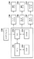
図1は、本発明の第1実施形態のインクジェット記録装置IJRAの構成の概要を示す外観斜視図である。図1において、キャリッジHCには、記録ヘッドIJHとインクタンクITとを内蔵した一体型インクジェットカートリッジIJCが搭載されている。キャリッジHCは、ガイドレール5003に支持されて記録媒体上を矢印a,b方向を往復移動し記録を行う。支持部材5016は記録ヘッドIJHの前面をキャップするキャップ部材5022を支持している。吸引器5015はキャップ内の吸引を行ない、キャップ内開口5023を介して記録ヘッドの吸引回復を行う。
Embodiments of the present invention will be described below in detail with reference to the drawings.
(First embodiment)
FIG. 1 is an external perspective view showing an outline of the configuration of the ink jet recording apparatus IJRA according to the first embodiment of the present invention. In FIG. 1, an integrated ink jet cartridge IJC that incorporates a recording head IJH and an ink tank IT is mounted on the carriage HC. The carriage HC is supported by the
図2はインクジェット記録装置IJRAの制御回路の構成を示すブロック図である。インタフェース1700に記録信号が入るとゲートアレイ1704とMPU1701との間で記録信号が記録用の記録データに変換される。そして、モータドライバ1706、1707が駆動されると共に、ヘッドドライバ1705に送られた記録データに従って記録ヘッドIJHが駆動され、記録が行われる。
FIG. 2 is a block diagram showing the configuration of the control circuit of the inkjet recording apparatus IJRA. When a recording signal enters the
次に本実施形態におけるインクジェット記録ヘッドIJHについて説明する。本実施形態のインクジェット記録ヘッドは、液体のインクを吐出するために利用されるエネルギとして熱エネルギを発生する手段を備え、その熱エネルギによってインクの状態変化を生起させる方式が採用された記録ヘッドである。この方式が用いられることにより、記録される文字や画像等の高密度化および高精細化を達成している。また本実施形態では、熱エネルギを発生する手段として電気熱変換素子を用い、この電気熱変換素子によりインクを加熱して膜沸騰させたときに発生する気泡による圧力を利用してインクを吐出している。 Next, the ink jet recording head IJH in this embodiment will be described. The ink jet recording head of the present embodiment is a recording head that includes a means for generating thermal energy as energy used for ejecting liquid ink, and adopts a system that causes a change in the state of the ink by the thermal energy. is there. By using this method, higher density and higher definition of recorded characters and images are achieved. In the present embodiment, an electrothermal conversion element is used as a means for generating thermal energy, and the ink is ejected by using the pressure generated by bubbles generated when the ink is heated by the electrothermal conversion element to boil the film. ing.
図3は、本実施形態のインクジェット記録ヘッドの一部切り欠いた斜視図である。電気熱変換素子である複数の電気熱変換素子(ヒータ)400が設けられた素子基板110と、この素子基板110の主面に積層されて接合されて複数のインクの流路を構成する流路形成部材111とを備えている。素子基板110は、例えば、ガラス、セラミックス、樹脂、金属等によって形成されており、一般にSiによって形成されている。素子基板110の主面上には、各インクの流路毎に、ヒータ400と、このヒータ400に電圧を印加する電極(図示せず)と、この電極に接続された配線(図示せず)が所定の配線パターンでそれぞれ設けられている。また、素子基板110の主面には、蓄熱の発散性を向上させる絶縁膜(図示せず)が、ヒータ400を被覆するように設けられている。また、素子基板110の主面には、気泡が消泡した際に生じるキャビテーションから保護するための保護膜(図示せず)が、絶縁膜を被覆するように設けられている。
FIG. 3 is a partially cutaway perspective view of the ink jet recording head of the present embodiment. An
流路形成部材111は、図3に示すように、インクが流動する複数のインク流路9と、インク流路9にインクを供給するインク供給口(供給室)6、およびインク滴を吐出する複数の吐出口4を有している。吐出口4は、素子基板110上のヒータ400に対向する位置に形成されている。
As shown in FIG. 3, the flow
このインクジェット記録ヘッドは素子基板上に複数のヒータ400および複数の吐出口4を有している。そして、各吐出口4の長手方向が平行に配列された第1の吐出口列と、供給室500を挟んで第1の吐出口列7に対向する位置に各吐出口4の長手方向が平行に配列された第2の吐出口列とを備えている。第1および第2の吐出口列は、隣接する各吐出口の間隔が600dpiピッチまたは1200dpiに形成されている。また、第2の吐出口列の各吐出口4は、第1の吐出口列の各吐出口4に対して、ドット配置の理由から必要に応じて、隣接する各吐出口間のピッチが互いにずれて配列されている。
This ink jet recording head has a plurality of
次に、インクジェット記録ヘッドの吐出口構造について説明する。
本実施形態の記録ヘッドは、インク流路の流抵抗の大きいものについては、吐出口のヒータの中心からのオフセット量(離れる量)を少なくしている。すなわち、ヒータ発生した気泡が消泡していく過程で、気泡が偏って消泡し吐出口からのメニスカスが抵抗の低い側から引き込まれる。このため、インク液滴の尾引きが曲がることがある。したがって、吐出口をオフセットすることにより、尾引き曲がりを低減するものである。
Next, the discharge port structure of the ink jet recording head will be described.
In the recording head according to the present embodiment, the offset amount (the amount of separation) from the center of the heater of the ejection port is reduced for the ink flow path having a large flow resistance. That is, in the process of defoaming the bubbles generated by the heater, the bubbles are biased and defoamed, and the meniscus from the discharge port is drawn from the low resistance side. For this reason, the tail of the ink droplet may be bent. Therefore, the tail bending is reduced by offsetting the discharge port.
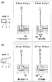
図4は本実施形態によるインクジェット記録ヘッドの吐出口構造を示した図である。同図(a)はインクジェット記録ヘッドの1つの基板に対して垂直な方向から見た複数の吐出口のうちの一部吐出口を示す平面透視図である。また、(b)は(a)のA−A‘線に沿った断面図、(c)は(a)のB−B’線に沿った断面図である。 FIG. 4 is a view showing the discharge port structure of the ink jet recording head according to the present embodiment. FIG. 2A is a perspective plan view showing some of the plurality of ejection ports as viewed from a direction perpendicular to one substrate of the ink jet recording head. Further, (b) is a cross-sectional view taken along line A-A 'in (a), and (c) is a cross-sectional view taken along line B-B' in (a).
本実施形態の記録ヘッドでは、流抵抗の異なるインク流路を配した吐出口が左右に配置してある。これらの吐出口に対応したインク流路9a、9bは、一端が圧力室11に連通されるとともに他端が吐出口フィルタ5を介してインク供給口6に連通されている。本実施形態における圧力室11とインク流路9の境界は、吐出口列方向の幅が変化しているところであり、吐出口列方向の幅が広くなっているところからが圧力室となっている。また吐出口4からインク液滴が飛翔される吐出方向と、供給路内を流動するインク液の流動方向とが直交して形成されている。
In the recording head of the present embodiment, the ejection ports provided with the ink flow paths having different flow resistances are arranged on the left and right. The
吐出口列方向の吐出口ピッチはそれぞれ42.3μm(600dpi)である。ヒータ1aは15μm×15μmの正方形であり、ヒータ1bは20μm×20μmの正方形である。吐出口列方向のオフセット量(離れる量)は21.2μm(1200dpi)である。また、吐出口4a、4bはそれぞれφ8、φ13径の円形であり、それぞれ約1.0pl、2.0plの吐出液滴が吐出する。インク流路9a、9bは、長さLa、Lbは共に17μm、幅Wa、Wbはそれぞれ10μm、15μmである。
The discharge port pitch in the discharge port array direction is 42.3 μm (600 dpi). The heater 1a is a square of 15 μm × 15 μm, and the
吐出口4a、4bの中心は、ヒータ1a、1bの中心に対してオフセットしてあり、流抵抗が小さいほどオフセット量(離れる量)は大きくなるよう配置されている。
The centers of the
そして、流路抵抗Rbは、以下の式により求められる。
L
Rb=μ∫D(y)dy/S(y)2
0
D(y)=12.0×(0.33+1.02(c(y)/d(y)+d(y)/c(y)))
Rb:電気熱変換素子から共通液室までの流抵抗
L :電気熱変換素子の中心から共通液室までの距離
y :共通液室からの距離
S(y):距離yの位置のインク流路断面積
D(y):距離yの位置のインク流路断面係数
c(y):距離yの位置のインク流路高さ
d(y):距離yの位置のインク流路幅
η:インク粘度
The flow path resistance Rb is obtained by the following equation.
L
R b = μ∫D (y) dy / S (y) 2
0
D (y) = 12.0 × (0.33 + 1.02 (c (y) / d (y) + d (y) / c (y)))
R b : Flow resistance from the electrothermal transducer to the common liquid chamber
L: distance from the center of the electrothermal transducer to the common liquid chamber y: distance from the common liquid chamber S (y): ink channel cross-sectional area D (y) at the position of distance y: ink flow at the position of distance y Road section coefficient c (y): Ink channel height d (y) at the position of distance y: Ink channel width η at the position of distance y: Ink viscosity
オフセット量は、インク流路の流抵抗Rbが0.03(P(ぺタ=1015)Pa・s/m3)以上0.2(P・Pa・s/m3)未満であるとき、吐出口オフセット量は、0〜3μmであることが望ましい。 The offset amount is discharged when the flow resistance Rb of the ink flow path is 0.03 (P (pet = 10 15 ) Pa · s / m 3) or more and less than 0.2 (P · Pa · s / m 3 ). The exit offset amount is desirably 0 to 3 μm.
また、インク流路の流抵抗が0.02(P・Pa・s/m3)以上0.06(P・Pa・s/m3)未満であるとき、吐出口オフセット量は、3〜6μmであることが望ましい。 Further, when the flow resistance of the ink flow path is 0.02 (P · Pa · s / m 3 ) or more and less than 0.06 (P · Pa · s / m 3 ), the discharge port offset amount is 3 to 6 μm. It is desirable that
本実施形態の記録ヘッドでは、流抵抗の大きいインク流路9aの吐出口4aはオフセット量は2μm、流抵抗の小さいインク流路9bの吐出口4bはオフセット量は5μmとなっている。また流抵抗は、インク流路9aは0.054(P・Pa・s/m3)であり、インク流路9bは0.023(P・Pa・s/m3)である。
In the recording head of this embodiment, the
図5および図6は、本実施形態における効果を説明する説明図である。図5(a)および(b)は、インク滴に関し液体シミュレーションを行なった結果を示すものである。 5 and 6 are explanatory diagrams for explaining the effects of the present embodiment. FIGS. 5A and 5B show the results of liquid simulation performed on ink droplets.
図5(a)および(b)は、図4(a)に示すAA‘断面から、吐出液滴がちぎれる寸前における見た断面図である。図4(a)および(b)は共に約2.0plのインクの吐出量である。そして、図4(a)の流路幅は10μmであり、(b)の流路幅は25μmである。すなわち、(a)に示す流路は、(b)に示す流路よりも流抵抗が大きいものである。 FIGS. 5A and 5B are cross-sectional views viewed from the AA ′ cross section shown in FIG. FIGS. 4A and 4B show an ink discharge amount of about 2.0 pl. And the flow path width of Fig.4 (a) is 10 micrometers, and the flow path width of (b) is 25 micrometers. That is, the flow path shown in (a) has a larger flow resistance than the flow path shown in (b).
吐出口オフセットが無い場合、図中左から明らかなように、(a)の流抵抗の大きい流路幅の場合、尾引き曲がり15eより、(b)の流抵抗が小さい流路幅25の場合の尾引き曲がり15gの方が大きい。
When there is no discharge port offset, as is clear from the left in the figure, in the case of the flow path width having a large flow resistance (a), in the case of the flow path width 25 having a smaller flow resistance than the
この尾引きの液滴がサテライトとなり、これが曲がると主滴と異なる方向に吐出し、記録画像に影響を与えるものである。この尾引き曲がりをなくすために、吐出口をオフセットしたのが図4(a)および(b)の図中右に示すものである。図から明らかなように比較的インク流路の流抵抗の大きい流路幅10μmの場合、オフセット量2μmのときに尾引き曲がり15fがほぼ直進する。一方、比較的インク流路の流抵抗の小さい流路幅25μmの場合、オフセット量8μmのときに尾引き曲がり15hがほぼ直進となる。このように、インク流路の流抵抗に応じてオフセット量を変えることにより、インクの尾引き曲がりを低減させ、インク滴を直進させることができる。
This tailing droplet becomes a satellite, and when it is bent, it is ejected in a different direction from the main droplet, affecting the recorded image. In order to eliminate this tail-bending, the discharge port is offset as shown on the right in FIGS. 4 (a) and 4 (b). As is apparent from the figure, in the case of a flow path width of 10 μm with a relatively large flow resistance of the ink flow path, the tail bend 15 f substantially goes straight when the offset amount is 2 μm. On the other hand, in the case of a flow path width of 25 μm with a relatively small flow resistance of the ink flow path, the
図6は、インク流路の流抵抗、吐出口オフセット量と液滴直進性の関係を示した図である。縦軸に吐出口のオフセット量を、横軸に流抵抗を示している。サテライト液滴の直進性はインク流路の流抵抗、吐出口オフセット量と関係があり、これらを適正にすることによって、サテライト滴の曲がりをなくすことができることができることがわかる。 FIG. 6 is a diagram showing the relationship between the flow resistance of the ink flow path, the discharge port offset amount, and the droplet straightness. The vertical axis represents the offset amount of the discharge port, and the horizontal axis represents the flow resistance. It can be seen that the straightness of the satellite droplet is related to the flow resistance of the ink flow path and the discharge port offset amount, and by making these appropriate, the bending of the satellite droplet can be eliminated.
(第2実施形態)
第1実施形態のインクジェット記録ヘッドは、吐出口が一列に配置してあるものであったが、本発明はこのような記録ヘッドに限定されるものではない。
(Second Embodiment)
The ink jet recording head of the first embodiment has the discharge ports arranged in a line, but the present invention is not limited to such a recording head.
図7は本実施形態によるインクジェット記録ヘッドの吐出口構造を示した図である。同図(a)はインクジェット記録ヘッドの1つの基板に対して垂直な方向から見た複数の吐出口のうちの一部吐出口を示す平面透視図である。また、(b)は(a)のC−C‘線に沿った断面図、(c)は(a)のD−D’線に沿った断面図である。 FIG. 7 is a view showing the discharge port structure of the ink jet recording head according to the present embodiment. FIG. 2A is a perspective plan view showing some of the plurality of ejection ports as viewed from a direction perpendicular to one substrate of the ink jet recording head. Further, (b) is a cross-sectional view taken along line C-C 'in (a), and (c) is a cross-sectional view taken along line D-D' in (a).
本実施形態の記録ヘッドでは、流抵抗の異なるインク流路を配した吐出口が左右に配置してある。これらの吐出口に対応したインク流路9b、9c、9dは、一端が圧力室11に連通されるとともに他端が吐出口フィルタ5を介してインク供給口6に連通されている。そして、吐出口4cと4dが千鳥状に交互に配置されている。
In the recording head of the present embodiment, the ejection ports provided with the ink flow paths having different flow resistances are arranged on the left and right. The
吐出口列方向の吐出口ピッチは、インク流路9bの側は42.3μm(600dpi)であり、インク流路9cおよび9dの側は21.3μm(1200dpi)である。ヒータ1cおよび1dは15μm×15μmの正方形であり、ヒータ1bは20μm×20μmの正方形である。また、吐出口4b、4c、4dはそれぞれφ13、φ11、φ8径の円形であり、それぞれ約2.0pl、1.5pl、1.0plの吐出液滴が吐出される。また、吐出口4b、4c、4dは、吐出口部が2段になっている構成である。このような構成にすることにより、吐出方向の吐出口部の流抵抗を低減し、吐出効率を良化した記録ヘッドである。インク流路9b、9c、9dは、長さLbおよびLcは共に17μm、Ldは65μm、幅Wbは15μm、幅WcおよびWdは10μmである。
The ejection port pitch in the ejection port array direction is 42.3 μm (600 dpi) on the
吐出口4b、4cの中心は、ヒータの中心に対してオフセットしてある。一方、吐出口4dは、インク流路9dの流抵抗が0.21(P・Pa・s/m3)であり、0.1(P・Pa・s/m3)を超えているためオフセットはしない構成となっている。また、インク流路9bのオフセット量(離れる量)は5μm、インク流路9cのオフセット量は2μmである。また流抵抗を計算すると、インク流路9bは0.023(P・Pa・s/m3)であり、インク流路9cは0.054(P・Pa・s/m3)となっている。
The centers of the
(第3実施形態)
本実施形態は、上述の実施形態と異なる吐出口部を備えたインクジェット記録ヘッドである。
(Third embodiment)
The present embodiment is an ink jet recording head provided with a discharge port portion different from the above-described embodiment.
図8は本実施形態によるインクジェット記録ヘッドの吐出口構造を示した図である。同図(a)はインクジェット記録ヘッドの1つの基板に対して垂直な方向から見た複数の吐出口のうちの一部吐出口を示す平面透視図である。また、(b)は(a)のC−C‘線に沿った断面図、(c)は(a)のD−D’線に沿った断面図である。 FIG. 8 is a view showing a discharge port structure of the ink jet recording head according to the present embodiment. FIG. 2A is a perspective plan view showing some of the plurality of ejection ports as viewed from a direction perpendicular to one substrate of the ink jet recording head. Further, (b) is a cross-sectional view taken along line C-C 'in (a), and (c) is a cross-sectional view taken along line D-D' in (a).
本実施形態の記録ヘッドでは、第2実施形態と同様に、流抵抗の異なるインク流路を配した吐出口が左右に配置してある。これらの吐出口に対応したインク流路9b、9c、9dは、一端が圧力室11に連通されるとともに他端が吐出口フィルタ5を介してインク供給口6に連通されている。そして、吐出口4cと4dが千鳥状に交互に配置されている。また、それぞれの寸法は、第2実施形態と同様のものである。
In the recording head of this embodiment, as in the second embodiment, the ejection ports provided with ink flow paths with different flow resistances are arranged on the left and right. The
本実施形態では、吐出口4b、4c、4dの中心は、ヒータの中心に対してオフセットしていないものである。これは吐出口4とのクリアランスを狭めた構成であって、製法上バラツキが最小限に抑えられる場合において作用効果が良い構成である。
In the present embodiment, the centers of the
(第4実施形態)
第2および第3実施形態では、インク供給口6の片側である吐出口4cと4dが千鳥状に交互に配置されているものであったが、本発明は、このようなものに限定されるものではない。すなわち、インク供給口6の両側の吐出口が千鳥状に交互に配置されているものであってもよい。
(Fourth embodiment)
In the second and third embodiments, the
図9は本実施形態によるインクジェット記録ヘッドの吐出口構造を示した図である。同図(a)はインクジェット記録ヘッドの1つの基板に対して垂直な方向から見た複数の吐出口のうちの一部吐出口を示す平面透視図である。また、(b)は(a)のC−C‘線に沿った断面図である。 FIG. 9 is a view showing a discharge port structure of the ink jet recording head according to the present embodiment. FIG. 2A is a perspective plan view showing some of the plurality of ejection ports as viewed from a direction perpendicular to one substrate of the ink jet recording head. Further, (b) is a cross-sectional view taken along the line C-C 'in (a).
このような構成をとることにより、小液滴をさらに高速に打ち込むことができる。 By adopting such a configuration, small droplets can be driven at a higher speed.
(その他)
上述した実施形態のヒータは、正方形の形態のものであるが、本発明はこのようなヒータに限定されるものではない。すなわち、ヒータは長方形であっても複数のヒータを備えた構成であってもよい。また、上述の実施形態の吐出口は、円形の形状をしたものであるが、本発明はこのような形態に限定されず、長円でも矩形であってもよい。
(Other)
Although the heater of embodiment mentioned above is a thing of a square form, this invention is not limited to such a heater. In other words, the heater may be rectangular or may have a plurality of heaters. Moreover, although the discharge outlet of the above-mentioned embodiment has a circular shape, the present invention is not limited to such a form, and may be an ellipse or a rectangle.
ILPA インクジェット記録装置
IJH 記録ヘッド
4 吐出口
5 吐出口フィルタ
6 インク供給口
9 インク流路
11 圧力室
ILPA Inkjet recording apparatus
Claims (5)
前記電気熱変換素子に対向する位置に形成される、インクを吐出する吐出口と、前記電気熱変換素子を内部に備える圧力室と、前記圧力室と前記インク供給口とを連通するインク流路と、を構成する、前記基板上に形成される部材と、
を備えるインクジェット記録ヘッドであって、
前記インク流路は相対的にインクの流抵抗の小さいインク流路と、相対的にインクの流抵抗の大きいインク流路とを含み、
前記相対的にインクの流抵抗の小さいインク流路に対応する吐出口は、前記インクの流抵抗の大きいインク流路に対応する吐出口よりも、当該吐出口の中心が対応する前記電気熱変換素子の中心に対して前記インク供給口からより離れるように配置されたことを特徴とするインクジェット記録ヘッド。 A substrate comprising: an ink supply port that supplies ink; and an electrothermal conversion element that generates thermal energy used to eject the ink;
An ink flow path that is formed at a position facing the electrothermal conversion element, that discharges ink, a pressure chamber that includes the electrothermal conversion element, and an ink flow path that communicates the pressure chamber and the ink supply port. And a member formed on the substrate,
An inkjet recording head comprising:
The ink flow path includes an ink flow path having a relatively small ink flow resistance and an ink flow path having a relatively large ink flow resistance,
The discharge port corresponding to the ink flow path having a relatively small ink flow resistance is more electrothermally converted than the discharge port corresponding to the ink flow path having a large ink flow resistance. An ink jet recording head, wherein the ink jet recording head is disposed so as to be further away from the ink supply port with respect to the center of the element.
Priority Applications (6)
| Application Number | Priority Date | Filing Date | Title |
|---|---|---|---|
| JP2007320143A JP5183181B2 (en) | 2007-12-11 | 2007-12-11 | Inkjet recording head |
| US12/328,404 US7963635B2 (en) | 2007-12-11 | 2008-12-04 | Inkjet print head |
| EP08170930A EP2070702B1 (en) | 2007-12-11 | 2008-12-08 | Inkjet print head |
| KR1020080125307A KR101098625B1 (en) | 2007-12-11 | 2008-12-10 | Inkjet print head |
| RU2008148731/12A RU2394688C1 (en) | 2007-12-11 | 2008-12-10 | Jet printing head |
| CN200810186610XA CN101456286B (en) | 2007-12-11 | 2008-12-11 | Inkjet print head |
Applications Claiming Priority (1)
| Application Number | Priority Date | Filing Date | Title |
|---|---|---|---|
| JP2007320143A JP5183181B2 (en) | 2007-12-11 | 2007-12-11 | Inkjet recording head |
Publications (3)
| Publication Number | Publication Date |
|---|---|
| JP2009143024A JP2009143024A (en) | 2009-07-02 |
| JP2009143024A5 JP2009143024A5 (en) | 2011-02-03 |
| JP5183181B2 true JP5183181B2 (en) | 2013-04-17 |
Family
ID=40350016
Family Applications (1)
| Application Number | Title | Priority Date | Filing Date |
|---|---|---|---|
| JP2007320143A Expired - Fee Related JP5183181B2 (en) | 2007-12-11 | 2007-12-11 | Inkjet recording head |
Country Status (6)
| Country | Link |
|---|---|
| US (1) | US7963635B2 (en) |
| EP (1) | EP2070702B1 (en) |
| JP (1) | JP5183181B2 (en) |
| KR (1) | KR101098625B1 (en) |
| CN (1) | CN101456286B (en) |
| RU (1) | RU2394688C1 (en) |
Families Citing this family (19)
| Publication number | Priority date | Publication date | Assignee | Title |
|---|---|---|---|---|
| US7735962B2 (en) | 2007-08-31 | 2010-06-15 | Canon Kabushiki Kaisha | Ink jet print head |
| JP5590813B2 (en) * | 2008-04-30 | 2014-09-17 | キヤノン株式会社 | Inkjet recording method, recording unit, and inkjet recording apparatus |
| JP2010000649A (en) | 2008-06-19 | 2010-01-07 | Canon Inc | Recording head |
| JP5393082B2 (en) * | 2008-08-29 | 2014-01-22 | キヤノン株式会社 | Liquid discharge head |
| JP4975120B2 (en) * | 2010-02-08 | 2012-07-11 | キヤノン株式会社 | Inkjet recording head |
| US10717278B2 (en) | 2010-03-31 | 2020-07-21 | Hewlett-Packard Development Company, L.P. | Noncircular inkjet nozzle |
| WO2011123120A1 (en) | 2010-03-31 | 2011-10-06 | Hewlett-Packard Development Company, L.P. | Noncircular inkjet nozzle |
| TWI499514B (en) * | 2010-10-01 | 2015-09-11 | Memjet Technology Ltd | Inkjet nozzle assembly with drop directionality control via independently actuable roof paddles |
| US8794745B2 (en) | 2011-02-09 | 2014-08-05 | Canon Kabushiki Kaisha | Liquid ejection head and liquid ejection method |
| JP6100009B2 (en) | 2012-02-28 | 2017-03-22 | キヤノン株式会社 | Liquid discharge head and recording apparatus |
| JP6173025B2 (en) | 2012-06-07 | 2017-08-02 | キヤノン株式会社 | Liquid discharge head |
| JP6271898B2 (en) | 2013-07-29 | 2018-01-31 | キヤノン株式会社 | Liquid ejection head and recording apparatus |
| US9044945B2 (en) * | 2013-07-30 | 2015-06-02 | Memjet Technology Ltd. | Inkjet nozzle device having high degree of symmetry |
| JP6183110B2 (en) * | 2013-09-30 | 2017-08-23 | ブラザー工業株式会社 | Liquid ejection apparatus, liquid ejection method, and program used for the liquid ejection apparatus |
| JP6532293B2 (en) | 2015-05-22 | 2019-06-19 | キヤノン株式会社 | Liquid discharge head, discharge element substrate and liquid discharge apparatus |
| JP6566770B2 (en) | 2015-07-30 | 2019-08-28 | キヤノン株式会社 | Liquid discharge head control method and liquid discharge apparatus |
| US10300698B2 (en) | 2017-06-05 | 2019-05-28 | Canon Kabushiki Kaisha | Liquid ejection head |
| JP6942537B2 (en) * | 2017-06-29 | 2021-09-29 | キヤノン株式会社 | Liquid discharge head |
| WO2023178334A1 (en) | 2022-03-18 | 2023-09-21 | Genentech, Inc. | Nano-suspensions and amorophous solid dispersions of hydrophobic agents and methods of use thereof |
Family Cites Families (18)
| Publication number | Priority date | Publication date | Assignee | Title |
|---|---|---|---|---|
| US4587534A (en) * | 1983-01-28 | 1986-05-06 | Canon Kabushiki Kaisha | Liquid injection recording apparatus |
| JPH0410941A (en) | 1990-04-27 | 1992-01-16 | Canon Inc | Droplet jet method and recorder equipped with same method |
| US5208605A (en) | 1991-10-03 | 1993-05-04 | Xerox Corporation | Multi-resolution roofshooter printheads |
| JP2785712B2 (en) * | 1994-09-30 | 1998-08-13 | 日本電気株式会社 | Ink jet print head |
| JP2001010056A (en) * | 1998-12-29 | 2001-01-16 | Canon Inc | Liquid ejection head, liquid ejecting method and liquid ejection recorder |
| EP1016525B1 (en) | 1998-12-29 | 2009-01-14 | Canon Kabushiki Kaisha | Liquid-ejecting head, liquid-ejecting method and liquid-ejecting printing apparatus |
| DE60140411D1 (en) * | 2000-09-06 | 2009-12-24 | Canon Kk | Ink jet recording head and method for its production |
| JP3871320B2 (en) | 2001-06-21 | 2007-01-24 | キヤノン株式会社 | Inkjet recording head |
| JP3927854B2 (en) * | 2002-04-23 | 2007-06-13 | キヤノン株式会社 | Inkjet recording head |
| JP2004001488A (en) | 2002-04-23 | 2004-01-08 | Canon Inc | Inkjet head |
| JP4027282B2 (en) | 2002-07-10 | 2007-12-26 | キヤノン株式会社 | Inkjet recording head |
| JP3762413B2 (en) | 2003-05-16 | 2006-04-05 | キヤノン株式会社 | Inkjet recording head |
| US7108352B2 (en) | 2003-05-16 | 2006-09-19 | Canon Kabushiki Kaisha | Liquid-jet recording head |
| TWI246462B (en) | 2003-06-10 | 2006-01-01 | Canon Kk | Ink-jet printhead substrate, driving control method, ink-jet printhead and ink-jet printing apparatus |
| JP2006187922A (en) * | 2005-01-05 | 2006-07-20 | Ricoh Co Ltd | Droplet ejection head, ink cartridge equipped with it, and inkjet recording apparatus |
| JP2006334935A (en) * | 2005-06-02 | 2006-12-14 | Canon Inc | Liquid discharge head |
| DE602007012869D1 (en) | 2006-05-02 | 2011-04-14 | Canon Kk | INK JET HEAD |
| JP5058719B2 (en) | 2007-08-30 | 2012-10-24 | キヤノン株式会社 | Liquid discharge head and ink jet recording apparatus |
-
2007
- 2007-12-11 JP JP2007320143A patent/JP5183181B2/en not_active Expired - Fee Related
-
2008
- 2008-12-04 US US12/328,404 patent/US7963635B2/en not_active Expired - Fee Related
- 2008-12-08 EP EP08170930A patent/EP2070702B1/en not_active Not-in-force
- 2008-12-10 RU RU2008148731/12A patent/RU2394688C1/en not_active IP Right Cessation
- 2008-12-10 KR KR1020080125307A patent/KR101098625B1/en not_active IP Right Cessation
- 2008-12-11 CN CN200810186610XA patent/CN101456286B/en not_active Expired - Fee Related
Also Published As
| Publication number | Publication date |
|---|---|
| KR101098625B1 (en) | 2011-12-23 |
| CN101456286B (en) | 2012-07-11 |
| JP2009143024A (en) | 2009-07-02 |
| CN101456286A (en) | 2009-06-17 |
| US7963635B2 (en) | 2011-06-21 |
| EP2070702B1 (en) | 2013-02-27 |
| EP2070702A1 (en) | 2009-06-17 |
| KR20090061598A (en) | 2009-06-16 |
| US20090147056A1 (en) | 2009-06-11 |
| RU2394688C1 (en) | 2010-07-20 |
Similar Documents
| Publication | Publication Date | Title |
|---|---|---|
| JP5183181B2 (en) | Inkjet recording head | |
| US8087759B2 (en) | Print head with offset ejection ports | |
| EP3189971B1 (en) | Liquid ejection head, liquid ejection apparatus, and method of supplying liquid | |
| JP7019318B2 (en) | Liquid discharge head and liquid discharge device | |
| JP5084478B2 (en) | Inkjet recording head and inkjet recording apparatus | |
| EP4116102B1 (en) | Method of supplying liquid | |
| JP5264123B2 (en) | Liquid discharge head | |
| JP4323947B2 (en) | Inkjet recording head | |
| EP1718469B1 (en) | Fluid ejection device | |
| JP4027281B2 (en) | Inkjet recording head | |
| JP2011025516A (en) | Inkjet recording head | |
| JP5393082B2 (en) | Liquid discharge head | |
| JP5213569B2 (en) | Inkjet recording head | |
| JP4553360B2 (en) | Inkjet recording head | |
| JPH11291500A (en) | Liquid delivery method and liquid delivery head | |
| JP6272002B2 (en) | Liquid discharge head and liquid discharge apparatus | |
| US20030179258A1 (en) | Methods and apparatus for reducing or minimizing satellite defects in fluid ejector systems | |
| JP3907685B2 (en) | Image forming apparatus | |
| JPH0948125A (en) | Recording head, ink jet recording apparatus using the same and recording method of recording head | |
| US20130229461A1 (en) | Recording method | |
| JP5020730B2 (en) | Liquid discharge head | |
| JP2011025556A (en) | Ink jet recording head | |
| JP2007301937A (en) | Recording head and board for the recording head | |
| US20130278678A1 (en) | Liquid ejecting head |
Legal Events
| Date | Code | Title | Description |
|---|---|---|---|
| RD02 | Notification of acceptance of power of attorney |
Free format text: JAPANESE INTERMEDIATE CODE: A7422 Effective date: 20101106 |
|
| A621 | Written request for application examination |
Free format text: JAPANESE INTERMEDIATE CODE: A621 Effective date: 20101201 |
|
| A521 | Request for written amendment filed |
Free format text: JAPANESE INTERMEDIATE CODE: A523 Effective date: 20101215 |
|
| A977 | Report on retrieval |
Free format text: JAPANESE INTERMEDIATE CODE: A971007 Effective date: 20120807 |
|
| A131 | Notification of reasons for refusal |
Free format text: JAPANESE INTERMEDIATE CODE: A131 Effective date: 20120821 |
|
| A521 | Request for written amendment filed |
Free format text: JAPANESE INTERMEDIATE CODE: A523 Effective date: 20121022 |
|
| TRDD | Decision of grant or rejection written | ||
| A01 | Written decision to grant a patent or to grant a registration (utility model) |
Free format text: JAPANESE INTERMEDIATE CODE: A01 Effective date: 20121218 |
|
| A61 | First payment of annual fees (during grant procedure) |
Free format text: JAPANESE INTERMEDIATE CODE: A61 Effective date: 20130115 |
|
| R151 | Written notification of patent or utility model registration |
Ref document number: 5183181 Country of ref document: JP Free format text: JAPANESE INTERMEDIATE CODE: R151 |
|
| FPAY | Renewal fee payment (event date is renewal date of database) |
Free format text: PAYMENT UNTIL: 20160125 Year of fee payment: 3 |
|
| LAPS | Cancellation because of no payment of annual fees |