JP5181799B2 - Whetstone - Google Patents
Whetstone Download PDFInfo
- Publication number
- JP5181799B2 JP5181799B2 JP2008104127A JP2008104127A JP5181799B2 JP 5181799 B2 JP5181799 B2 JP 5181799B2 JP 2008104127 A JP2008104127 A JP 2008104127A JP 2008104127 A JP2008104127 A JP 2008104127A JP 5181799 B2 JP5181799 B2 JP 5181799B2
- Authority
- JP
- Japan
- Prior art keywords
- grindstone
- grinding
- workpiece
- layer
- groove
- Prior art date
- Legal status (The legal status is an assumption and is not a legal conclusion. Google has not performed a legal analysis and makes no representation as to the accuracy of the status listed.)
- Expired - Fee Related
Links
Images


Description
本発明は、外周に砥石層が形成されており、砥石層の外周面と工作物との接触面に向けて研削液を供給しながら工作物を研削加工する砥石に関するものである。 The present invention relates to a grindstone in which a grindstone layer is formed on an outer periphery, and a workpiece is ground while supplying a grinding liquid toward a contact surface between the outer circumferential surface of the grindstone layer and the workpiece.
従来、研削盤に備えられた砥石で工作物を研削加工するときには、砥石と工作物との研削点に研削液を供給して冷却及び潤滑することにより研削熱による工作物の研削焼け、熱歪み等を防止している。しかし、砥石と工作物との研削点に向けて研削液を供給した場合、砥石と工作物との間で研削液に動圧が発生し、また、工作物に穴や溝がある場合には、穴や溝により圧力が変化し、砥石と工作物との間で相対変位を生じ、工作物の研削加工精度が低下するという問題があった。かかる研削液に発生する動圧による研削加工精度の低下を防ぐための技術が、特許文献1に開示されている。
Conventionally, when grinding a workpiece with a grindstone provided in a grinding machine, the grinding fluid is supplied to the grinding point between the grindstone and the workpiece, cooled and lubricated, thereby grinding and burning the workpiece by grinding heat and thermal distortion. Etc. are prevented. However, when grinding fluid is supplied toward the grinding point between the grinding wheel and the workpiece, dynamic pressure is generated in the grinding fluid between the grinding wheel and the workpiece, and when there are holes or grooves in the workpiece. The pressure changes due to the holes and grooves, causing relative displacement between the grindstone and the workpiece, resulting in a problem that the grinding accuracy of the workpiece is lowered. A technique for preventing a decrease in grinding accuracy due to dynamic pressure generated in such a grinding fluid is disclosed in
特許文献1に記載の技術では、砥石と工作物とが接触する研削点に研削液を供給するクーラントノズルに供給する研削液圧を高低2段階に切替え可能な研削液供給装置を設け、砥石の工作物への送り速度が大きい粗研削時には研削液圧を高圧に、送り速度が小さい仕上げ研削時、スパークアウト研削時には低圧に切替えることにより、研削液に生じる動圧によって研削加工精度が悪化することを防止している。
上記従来技術では、砥石の研削面と工作物とが接触する接触面に向けて供給された研削液に生じた動圧を開放することができず、特に、砥石及び工作物の回転数を上げて研削能率を高くした場合、研削液に生じる動圧によって研削加工精度が悪化する。そこで、本出願人は、砥石と工作物とが接触する接触面を上下に貫通するように少なくとも1本の傾斜溝を設けた砥石を提案している。かかる砥石によれば、接触面に向けて供給された研削液の排出性を向上させ、工作物に対する砥石の接触弧長さを減少させて、研削液に発生する動圧を開放し、工作物の加工精度を高めることができる。ところが、傾斜溝を設けることにより砥石の研削に作用する砥粒体積(砥粒数)が減少するので、砥石の寿命が短くなる場合があり、研削盤において砥石交換の作業頻度が高くなる。 In the above prior art, it is not possible to release the dynamic pressure generated in the grinding fluid supplied toward the contact surface where the grinding surface of the grindstone and the workpiece contact, and in particular, the rotational speed of the grindstone and the workpiece is increased. When the grinding efficiency is increased, the grinding accuracy is deteriorated by the dynamic pressure generated in the grinding fluid. Therefore, the present applicant has proposed a grindstone provided with at least one inclined groove so as to vertically penetrate a contact surface where the grindstone and the workpiece come into contact with each other. According to such a grindstone, the drainage of the grinding fluid supplied toward the contact surface is improved, the contact arc length of the grindstone with respect to the workpiece is reduced, the dynamic pressure generated in the grinding fluid is released, and the workpiece The processing accuracy can be increased. However, by providing the inclined grooves, the abrasive volume (number of abrasive grains) acting on the grinding of the grinding wheel is reduced, so that the life of the grinding wheel may be shortened, and the work frequency of grinding wheel replacement in the grinding machine increases.
本発明は、工作物の研削加工を高精度に行える長寿命の砥石を提供することである。 The present invention is to provide a long-life grindstone capable of grinding a workpiece with high accuracy.
上記の課題を解決するため、請求項1に係る発明の構成上の特徴は、外周に砥石層が形成されており、前記砥石層の外周面と工作物との接触面に向けて研削液を供給しながら前記工作物を研削加工する砥石において、
前記砥石層の内周面に砥石円周方向に対して所定の角度傾斜し、等間隔に複数の傾斜溝が刻設され、
前記傾斜溝と前記接触面の砥石円周方向と平行な一方の縁の延長線との交点を一方交点、他方の縁の延長線との交点を他方交点と定義した場合、一の傾斜溝の他方交点と、一の傾斜溝と隣接する傾斜溝の一方交点とが砥石円周方向において所定のオーバラップ量だけオーバラップし、
前記砥石層の摩耗により前記傾斜溝が前記砥石層の外周面に出現したとき、前記接触面の砥石円周方向長さが前記オーバラップ量よりも小さくなるように、前記工作物に対する前記砥石の切込み量と、前記傾斜溝の傾斜角度及び間隔との少なくとも一方が設定されていることである。
In order to solve the above-mentioned problem, the structural feature of the invention according to
The inner circumferential surface of the grinding wheel layer is inclined at a predetermined angle with respect to the grinding wheel circumferential direction , and a plurality of inclined grooves are engraved at equal intervals.
When the intersection of the inclined groove and the extension line of one edge parallel to the grinding wheel circumferential direction of the contact surface is defined as one intersection point and the intersection point of the other edge extension line is defined as the other intersection point, The other intersection and the one intersection of one inclined groove and the adjacent inclined groove overlap by a predetermined overlap amount in the grinding wheel circumferential direction,
When the inclined grooves appear on the outer peripheral surface of the grindstone layer due to wear of the grindstone layer, the grindstone circumferential length of the contact surface is smaller than the overlap amount of the grindstone with respect to the workpiece. That is, at least one of the cutting depth and the inclination angle and interval of the inclined groove is set .
請求項2に記載の発明の構成上の特徴は、請求項1に記載の砥石において、前記砥石層の外周面と前記工作物との接触面内であって、前記砥石層を円周上の任意の位置で砥石軸と平行に、且つ、砥石径の方向に切断したときの当該切断線上に存在する前記傾斜溝の幅の和が常に等しいことである。
A structural feature of the invention according to
請求項3に記載の発明の構成上の特徴は、請求項1又は2に記載の砥石において、前記砥石層の内周面側から外周面側に向かって溝幅が徐々に縮小する傾斜溝が刻設されていることである。
請求項4に記載の発明の構成上の特徴は、請求項1又は2に記載の砥石において、前記砥石層の内周面側からの溝深さが異なる複数の傾斜溝が刻設されていることである。
, The feature in construction of the invention according to claim 3, claim Te grindstone smell according to 1 or 2, tilt the previous SL groove width toward the outer peripheral side from the inner peripheral surface of the grinding wheel layer is gradually reduced The groove is engraved.
A structural feature of the invention according to claim 4 is that, in the grindstone according to
請求項1に係る発明によれば、外周に砥石層が形成されており、砥石層の外周面と工作物との接触面に向けて研削液を供給しながら工作物を研削加工する砥石において、砥石層の内周面に傾斜溝を刻設しているため、砥石層の外周面から傾斜溝の底部に達するまでは一般的な砥石と同様に作用する。即ち、砥石の使用が最初のうちは研削加工時やツルーイング時に発生する切粉が砥粒間に存在する気孔に殆ど詰まっていないので、砥石の研削面と工作物とが接触する接触面に向けて供給された研削液に生じた動圧を開放することができ、高精度な研削加工を行うことができる。更に、砥石の使用が最初のうちは砥石の研削加工に作用する砥粒体積(砥粒数)は傾斜溝が無い分だけ増加しているので長寿命となる。しかし、このまま砥石の使用が進むと切粉が気孔に詰まりだす(目詰まり)ので、研削液に生じた動圧を開放することができず、研削加工精度が低下するが、砥石層が摩耗していき傾斜溝が出現すると以下の作用により研削液に生じた動圧を開放することができ、高精度な研削加工を行うことができる。
According to the invention according to
即ち、上方から供給された研削液が傾斜溝を通って上方及び下方から流出し、研削面と工作物との間に発生する研削液の動圧を開放することができる。これにより、研削液の供給量を減少させなくても、工作物が研削液の動圧よって砥石から離間する方向に変位され、或いは研削液に発生する動圧が変動して工作物が砥石から離間する距離が変化することがなくなり、工作物の研削加工精度を高めることができる。 That is, the grinding fluid supplied from above flows out from above and below through the inclined groove, and the dynamic pressure of the grinding fluid generated between the grinding surface and the workpiece can be released. As a result, even if the supply amount of the grinding fluid is not reduced, the workpiece is displaced in the direction away from the grindstone due to the dynamic pressure of the grinding fluid, or the dynamic pressure generated in the grinding fluid varies so that the workpiece is removed from the grindstone. The separation distance does not change, and the grinding accuracy of the workpiece can be increased.
特に、傾斜溝と、接触面の砥石円周方向と平行な一方の縁の延長線との交点を一方交点、他方の縁の延長線との交点を他方交点と定義した場合、一の傾斜溝の他方交点と、一の傾斜溝と隣接する傾斜溝の一方交点とが砥石円周方向において所定のオーバラップ量だけオーバラップし、接触面の砥石円周方向長さがオーバラップ量よりも小さくなるようにするので、少なくとも1本の傾斜溝が砥石の研削面と工作物とが接触する接触面を上下方向に貫通し、上方から供給された研削液が傾斜溝を通って上方及び下方から流出し、研削面と工作物との間に発生する研削液の動圧を開放することができる。これにより、研削液の供給量を減少させなくても、工作物が研削液の動圧よって砥石から離間する方向に変位され、或いは研削液に発生する動圧が変動して工作物が砥石から離間する距離が変化することがなくなり、工作物の研削加工精度を高めることができる。
In particular , when the intersection of the inclined groove and the extension line of one edge parallel to the circumferential direction of the grinding wheel of the contact surface is defined as one intersection point, and the intersection point of the extension line of the other edge is defined as the other intersection point, one inclined groove And the other intersection of one inclined groove and one intersection of the adjacent inclined grooves overlap each other by a predetermined overlap amount in the grinding wheel circumferential direction, and the grinding wheel circumferential length of the contact surface is smaller than the overlap amount. Therefore, at least one inclined groove penetrates the contact surface where the grinding surface of the grindstone and the workpiece come into contact in the vertical direction, and the grinding fluid supplied from above passes through the inclined groove from above and below. The dynamic pressure of the grinding fluid that flows out and is generated between the grinding surface and the workpiece can be released. As a result, even if the supply amount of the grinding fluid is not reduced, the workpiece is displaced in the direction away from the grindstone due to the dynamic pressure of the grinding fluid, or the dynamic pressure generated in the grinding fluid varies so that the workpiece is removed from the grindstone. The separation distance does not change, and the grinding accuracy of the workpiece can be increased.
請求項2に係る発明によれば、傾斜溝による研削液に発生する動圧の低減効果は傾斜溝の幅に比例するが、研削面全周にわたって傾斜溝の幅が一定となるように傾斜溝を刻設しているので研削面全周にわたって動圧低減効果も一定となり、工作物に対しむらのない研削加工が可能となる。
According to the invention of
請求項3に係る発明によれば、砥石層の内周面側から外周面側に向かって溝幅(溝面積)が徐々に縮小する傾斜溝を刻設しているため、砥石の使用が進むに従って溝幅(溝面積)は拡大することになる。よって、砥石の使用が進むに従って目詰まりが増加しても、溝幅(溝面積)が徐々に拡大するために研削液の動圧を効果的に開放することができ、工作物の研削加工精度を高めることができる。
According to the invention which concerns on Claim 3 , since the inclination groove | channel which groove width (groove area) reduces gradually toward the outer peripheral surface side from the inner peripheral surface side of a grindstone layer, use of a grindstone advances. Accordingly, the groove width (groove area) is increased. Therefore, even if clogging increases as the use of the grindstone progresses, the groove width (groove area) gradually increases, so the dynamic pressure of the grinding fluid can be effectively released, and the grinding accuracy of the workpiece Can be increased.
請求項4に係る発明によれば、砥石層の内周面側からの溝深さが異なる複数の傾斜溝を刻設しているため、砥石の使用が進むに従って出現する傾斜溝の本数は増加することになる。よって、砥石の使用が進むに従って目詰まりが増加しても、傾斜溝の本数が順次増加するために研削液の動圧を効果的に開放することができ、工作物の研削加工精度を高めることができる。
According to the invention which concerns on Claim 4 , since the several inclined groove from which the groove depth from the inner peripheral surface side of a grindstone layer differs is engraved, the number of the inclined grooves which appear as the use of a grindstone progresses increases. Will do. Therefore, even if clogging increases as the use of the grindstone progresses, the number of inclined grooves gradually increases, so the dynamic pressure of the grinding fluid can be effectively released, and the grinding accuracy of the workpiece can be improved. Can do.
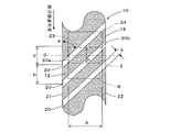
以下、本発明の実施の形態に係る砥石を図面に基づいて説明する。図1は、セグメントタイプの砥石チップ(砥石層)11を含む砥石10を示し、この砥石10の砥石チップ11は、超砥粒をビトリファイドボンドで結合した砥粒層12が外側に形成され、超砥粒を含まない下地層13が砥粒層12の内側に重ねて一体的に形成されている。砥石10は、砥粒層12と下地層13からなる複数の円弧状の砥石チップ11が、鉄又はアルミニウム等の金属、或いは樹脂等で成形された円盤状のコア14の外周面に並べられ、下地層13の底面で接着剤によりコア14に貼付されて構成されている。砥石チップ11の内周面18には、複数の傾斜溝20が、下地層13の底面から砥粒層12の内部途中に至る深さ、即ち傾斜溝20の底部から砥粒層12の上面までが所定厚さとなるように刻設されている。
Hereinafter, a grindstone according to an embodiment of the present invention will be described with reference to the drawings. FIG. 1 shows a
図2は、円弧状の砥石チップ11を示すもので、砥粒層12は、CBN、ダイヤモンド等の超砥粒16をビトリファイドボンド17で3mm〜5mmの厚さに結合したものであり、集中度調整用に超砥粒の代わりに酸化アルミニウム(Al2O3)等の粒子が骨材として混入されている場合もある。また、下地層13は、下地粒子19をビトリファイドボンド17で1mm〜3mmの厚さに結合したものである。また、傾斜溝20の底部から砥粒層12の上面までの厚さTは、新品の砥石10が使用につれて砥粒層12が摩耗して傾斜溝20の底部に達したときに目詰まりの許容限度を超えた状態になっているように設定されており、例えば#120のCBN砥粒の砥粒層12の場合で1mmである。ビトリファイドボンド17を採用すると、有気孔の特性から、切り屑の排出性に優れ、切れ味が良好となるため、砥石摩耗量を少なくして良好な表面あらさに研削加工することができる。また、結合剤としては、ビトリファイドボンド17の他に、レジンボンド又はメタルボンド等を使用することもできる。
FIG. 2 shows an arc-
砥石10は、図3に示す研削盤30の砥石台31に軸線O回りに回転駆動可能に軸承された砥石軸32にコア14で装着される。研削盤30の工作物支持装置33には工作物Wが回転駆動可能に支承され、砥石台31の前進により砥石10の砥粒層12に形成された研削面15(砥石チップ11の外周面)が工作物Wに接触面Sで当接して工作物Wの外周面を研削加工する。砥石10は、使用初期においては傾斜溝20が無い通常の研削面15にて工作物Wを研削加工するが、研削加工サイクルやツルーイングサイクルが繰り返されて摩耗が進んだ使用中期においては傾斜溝20が出現した研削面15にて工作物Wを研削加工するようになっている。
The
即ち、砥石10は、砥石チップ11の外周面から傾斜溝20の底部に達するまでは一般的な砥石と同様に作用するが、かかる使用初期においては研削加工時やツルーイング時に発生する切粉が砥粒間に存在する気孔に殆ど詰まっていないので、砥石10の研削面15と工作物Wとが接触する接触面に向けて供給された研削液に生じた動圧を開放することができ、高精度な研削加工を行うことができる。更に、砥石10の使用初期においては砥石10の研削加工に作用する砥粒体積(砥粒数)は傾斜溝20が無い分だけ増加しているので砥石寿命を長寿化させることができる。
That is, the grindstone 10 acts in the same manner as a general grindstone until it reaches the bottom of the
しかし、研削加工サイクルやツルーイングサイクルが繰り返されて摩耗が進んだ使用中期においては切粉が気孔に詰まりだす(目詰まり)。例えば#120のCBN砥粒径は125μmであり、気孔も同程度の大きさで存在するが、ツルーイングサイクルは、例えば、片側10μm(2.5μm×4回)であるために気孔に目詰まりした切粉を除去することは殆ど不可能である。よって、研削液に生じた動圧を開放することができず、研削加工精度が低下するが、砥粒層12が摩耗していくと傾斜溝20が出現して以下で説明する作用により研削液に生じた動圧を開放することができ、高精度な研削加工を行うことができる。
However, in the middle period of use where wear has progressed due to repeated grinding and truing cycles, chips clog the pores (clogging). For example, the # 120 CBN abrasive grain size is 125 μm, and the pores are about the same size, but the truing cycle is clogged due to, for example, 10 μm (2.5 μm × 4 times) on one side. It is almost impossible to remove chips. Therefore, the dynamic pressure generated in the grinding fluid cannot be released and the grinding accuracy is lowered. However, when the
図4乃至図6に示すように、砥石10の砥石チップ11の内周面18には、複数の傾斜溝20が、下地層13の底面から砥粒層12の内部に至るまでの深さhで砥石周方向と平行な下地層13及び砥粒層12の両側面21,22を突き抜けて下地層13及び砥粒層12に設けられている。即ち、砥石チップ11の内周面18には、砥石円周方向に対して所定の傾斜角度αだけ傾斜した複数の傾斜溝20が、所定のピッチPで等間隔に、且つ、傾斜溝20と、接触面Sの砥石円周方向と平行な一方の縁Saの延長線23との交点を一方交点20a、他方の縁Sbの延長線24との交点を他方交点20bと定義した場合、一の傾斜溝20の他方交点20bと、一の傾斜溝20と隣接する傾斜溝20の一方交点20aとが砥石円周方向においてオーバラップ量Vだけオーバラップするように刻設されている。
As shown in FIGS. 4 to 6, on the inner
そして、砥石10の研削加工サイクルやツルーイングサイクルによる摩耗が進んで傾斜溝20が出現したときの研削面15と工作物Wとの接触面Sの砥石円周方向長さLがオーバラップ量Vよりも小さくなるように、工作物Wに対する砥石10の切込み量tと、傾斜溝20の傾斜角度α及び間隔(ピッチ)Pとの少なくとも一方が設定されている。接触面Sは、砥石10の外周円と工作物Wの外周円とが交差する交点と工作物Wの幅Aとによって区画される砥石10の研削面15の領域であり、砥石円周方向と平行な一方縁Sa、他方縁Sb、及び砥石軸線方向と平行な一方縁Sf、他方縁Srによって囲まれている。
Then, the grinding wheel circumferential length L of the contact surface S between the grinding
砥石10の研削面15と工作物Wとの接触面Sの砥石円周方向長さLがオーバラップ量Vよりも小さくされているので、接触面Sに上方から供給された研削液が接触面Sを貫通する傾斜溝20を通って上方及び下方から流出し、研削面15と工作物Wとの間に発生する研削液の動圧を開放することができる。これにより、工作物Wが研削液の動圧よって砥石10から離間する方向に変位され、或いは研削液に発生する動圧が変動して工作物Wが砥石10から離間する距離が変化することがなくなり、研削された工作物Wの研削加工精度を高めることができる。
Since the grinding wheel circumferential length L of the contact surface S between the grinding
砥石10の研削面15を展開して示した図4、図6から明らかなように、一の傾斜溝20が接触面Sの他方の縁Sbの延長線24と交差する他方交点20bと、一の傾斜溝20と隣接する傾斜溝20が接触面Sの一方の縁Saの延長線23と交差する一方交点20aとが砥石円周方向においてオーバラップするオーバラップ量Vと、傾斜溝20の傾斜角度αと、隣接する傾斜溝20の間隔P、例えば円周方向ピッチと、接触面Sの軸線方向長さである工作物Wの幅Aとの関係は、
V=A/tanα−P・・・(1)
となる。
As is apparent from FIGS. 4 and 6 in which the grinding
V = A / tan α−P (1)
It becomes.
従って、オーバラップ量Vより接触面Sの円周方向長さLが小さい条件、
L<A/tanα−P・・・(2)
を満たせば、砥石10の回転位相に拘らず、少なくとも1本の傾斜溝20が接触面Sを上下方向に貫通することとなり、接触面Sに流入した研削液により研削面15と工作物Wとの間に発生する動圧を接触面Sの上方及び下方の両方から開放することができる。これに対し、この条件を満たさないと、砥石10の回転位相によっては、いずれの傾斜溝20も接触面Sを上下方向に貫通しないので、すなわち、接触面Sに対して傾斜溝20が上方にしか開口していないと接触面Sの下方では動圧が開放されず、同様に傾斜溝20が下方にしか開口していないと接触面Sの上方では研削液の動圧は開放されない。
Therefore, the condition where the circumferential length L of the contact surface S is smaller than the overlap amount V,
L <A / tan α-P (2)
Is satisfied, regardless of the rotational phase of the
砥石10が工作物Wと接触する接触面Sの砥石円周方向長さLは、図7(b)に示すように、砥石10の外周円と工作物Wの外周円とが交差する交点を結ぶ線分の長さとする。接触面Sの砥石円周方向長さLは、砥石10及び工作物Wの直径に比して極めて小さいので、砥石10の外周円と工作物Wの外周円とが交差する交点を結ぶ線分の長さで近似することができる。
The grinding wheel circumferential length L of the contact surface S where the grinding
工作物Wの半径をR1、砥石10の半径をR2、砥石10の工作物Wへの切込み量をtとすると、図7(c)に示すように、工作物Wと砥石10との中心間距離Cは、
C=R1+R2−t・・・(3)
となる。砥石10の外周円と工作物Wの外周円とが交差する交点Dから工作物Wの中心Eと砥石10の中心Fとを結ぶ線分EFに垂直に下ろした線分が線分EFと交差する点をHとし、線分DH、EH、FHの長さを夫々x、y、zとすると、
R12=x2+y2・・・(4)
R22=x2+z2・・・(5)
となり、
C=y+zからy2=(C−z)2・・・(6)
となる。式(4)、(5)、(6)をxについて解くと、
x=√(R22−((C2+R22−R12)/2C)2)・・・(7)
となる。そして、砥石10が工作物Wと接触する接触面Sの円周方向長さLは、
L=2x・・(8)
となる。
If the radius of the workpiece W is R1, the radius of the
C = R1 + R2-t (3)
It becomes. A line segment perpendicular to the line segment EF connecting the center E of the work piece W and the center F of the grindstone 10 from the intersection point D where the outer circumference circle of the
R1 2 = x 2 + y 2 (4)
R2 2 = x 2 + z 2 (5)
And
C = y + z to y 2 = (C−z) 2 (6)
It becomes. Solving equations (4), (5), and (6) for x,
x = √ (R2 2 − ((C 2 + R2 2 −R1 2 ) / 2C) 2 ) (7)
It becomes. And the circumferential direction length L of the contact surface S where the grindstone 10 contacts the workpiece W is:
L = 2x (8)
It becomes.
接触面Sの円周方向長さLがオーバラップ量Vと等しい場合、式(1)、(8)から、
L=2x=V=A/tanα−Pとなり、そのときの切込み量t0は、
t0=R1+R2−√(R12−((A/tanα−P)/2)2)
−√(R22−((A/tanα−P)/2)2)・・・(9)
となる。従って、工作物W及び砥石10の半径R1,R2、工作物Wの幅A、傾斜溝20の傾斜角度α及び円周方向ピッチPが決まっている場合は、砥石10の工作物Wへの切込み量tをt0より小さく設定すると、接触面Sの円周方向長さLがオーバラップ量Vより小さくなる。
When the circumferential length L of the contact surface S is equal to the overlap amount V, from the equations (1) and (8),
L = 2x = V = A / tan α−P, and the cutting amount t0 at that time is
t0 = R1 + R2-√ (R1 2 − ((A / tan α−P) / 2) 2 )
-√ (R2 2 -((A / tan α-P) / 2) 2 ) (9)
It becomes. Therefore, when the radii R1, R2 of the workpiece W and the
また、工作物W及び砥石10の半径R1,R2、工作物Wの幅A、砥石10の工作物Wへの切込み量t、及び傾斜溝20の傾斜角度α及び円周方向ピッチPの一方が決まっている場合は、式(9)が成立するように、傾斜溝20の傾斜角度α0及び円周方向ピッチP0の他方を設定し、円周方向ピッチP又は傾斜角度αを、この設定した円周方向ピッチP0又は傾斜角度α0より小さく設定すると、接触面Sの円周方向長さLがオーバラップ量Vより小さくなる。このように設定された傾斜溝20の本数nは、n=2π×R2/Pとなる。
Further, one of the radii R1 and R2 of the workpiece W and the
次に、本実施の形態に係る砥石10を用いて工作物Wを研削加工する方法について説明する。砥石10は図3に示す研削盤30の砥石台31に軸承された砥石軸32にコア14で装着されて回転駆動され、工作物Wは主軸台及び心押台からなる工作物支持装置33に支承されて回転駆動される。砥石カバー34に取り付けられたクーラントノズル35から砥石10の研削面15と工作物Wとの間の接触面Sに向けて研削液が供給され、砥石台31が工作物Wに向かって研削送りされ、砥石10により工作物Wが研削加工される。
Next, a method for grinding the workpiece W using the
砥石10の使用初期においては研削面15に傾斜溝20が出現していないが、研削加工時やツルーイング時に発生する切粉が砥粒間に存在する気孔に殆ど詰まっていないので、砥石10の研削面15と工作物Wとが接触する接触面に向けて供給された研削液に生じた動圧を開放することができ、工作物Wは高精度に研削加工される。このとき、砥石10の使用初期においては砥石10の研削加工に作用する砥粒体積(砥粒数)は傾斜溝20が無い分だけ増加しているので長寿命となる。
In the initial stage of use of the
砥石10の使用中期においては切粉が気孔に詰まりだす(目詰まり)が、研削面15に傾斜溝20が出現して研削液に生じた動圧を開放することができる。即ち、砥石10の回転位相に拘らず、少なくとも1本の傾斜溝20が接触面Sを上下方向に貫通するので、研削面15と工作物Wとの間に発生する研削液の動圧を接触面Sの上方及び下方から開放することができる。これにより、工作物Wが研削液に生じる動圧によって砥石10から離間する方向に変位され、或いは研削液に生じる動圧が変動して工作物Wが砥石10から離間する距離が変化することがなくなり、工作物Wは高精度に研削加工される。
In the middle period of use of the
例えば図8に示すように、ベース円部Wb、トップ部Wt、ベース円部Wbとトップ部Wtとを接続する一対のリフト部Wlとを含むカムを研削する場合、カムのリフト部Wlは曲率が小さいので、砥石10との接触面Sの円周方向長さが一番長くなる。このように接触面Sの円周方向長さが長くなるときは、接触面Sに向けて供給された研削液の動圧が大きくなる。しかし、隣接する傾斜溝20のオーバラップ量Vをこの一番長い砥石円周方向長さよりも大きくすることにより、砥石10の回転位相に拘らず、少なくとも1本の傾斜溝20が接触面Sを上下方向に貫通するので、研削面15と工作物Wとの間に発生する研削液の動圧を接触面Sの上方及び下方から開放することができる。これにより、仕上げ研削において研削液の供給量を減少させなくても、カムが研削液の動圧よって砥石から離間する方向に変位され、或いは研削液に発生する動圧が変動してカムが砥石から離間する距離が変化することがなくなり、カムの研削加工精度を高めて研削能率を向上することができる。
For example, as shown in FIG. 8, when a cam including a base circle portion Wb, a top portion Wt, and a pair of lift portions Wl connecting the base circle portion Wb and the top portion Wt is ground, the cam lift portion Wl has a curvature. Therefore, the circumferential length of the contact surface S with the
図9は、砥石10に設けられる第2形態の傾斜溝88を図4に対応させて示す図であり、同一構成部材は同一番号を付して詳細な説明は省略する。砥石10の砥石チップ11の内周面18には、砥石円周方向に対して所定の傾斜角度αだけ傾斜した複数の傾斜溝88が、下地層13の底面から砥粒層12の内部に至るまでの深さ(図5に示す傾斜溝20と同一のh)で砥石周方向と平行な下地層13及び砥粒層12の両側面21,22を突き抜けて下地層13及び砥粒層12に刻設されている。以上の点は図4等に示す第1形態の傾斜溝20と同一であるが、以下の点で異なるものとなっている。
FIG. 9 is a view showing the
傾斜溝88は、砥粒層12の外周面と工作物Wとの接触面S内であって、砥粒層12を円周上の任意の位置で砥石軸と平行に、且つ、砥石径の方向に切断したときの当該切断線CL上に存在する傾斜溝88の幅w1,w2の和が常に等しくなるように、つまり、1つの傾斜溝88の幅w0=w1+w2となるように所定のピッチPaで等間隔に刻設されている。尚、切断線CL上に存在する傾斜溝88の幅は、接触面S内に存在する傾斜溝88の面積に置き換えて定義しても良い。
即ち、傾斜溝88は、接触面Sの砥石円周方向に平行な一方の縁Saと砥石軸線方向と平行な一方の縁Sfとの交点xaに、一の傾斜溝88の一方の縁部88aが位置したとき、砥石円周方向に平行な他方の縁Sbと砥石軸線方向と平行な一方の縁Sfとの交点xbに、一の傾斜溝88と隣接する傾斜溝88の一方の縁部88aが位置するように刻設されている。
The
That is, the
ここで、傾斜溝88による研削液に発生する動圧の低減効果は傾斜溝88の幅w0(=w1+w2)に比例する。よって、上述したように砥粒層12の外周面の全周にわたって傾斜溝88の幅w0(=w1+w2)が一定となるように傾斜溝88を刻設することにより、砥粒層12の外周面全周にわたって動圧低減効果も一定とすることができる。この結果、工作物Wに対しむらのない研削加工が可能となる。更に、接触面Sに上方から供給された研削液が接触面Sを貫通する傾斜溝88を通って上方及び下方から流出し、砥粒層12の外周面と工作物Wとの間に発生する研削液の動圧を開放することができる。これにより、工作物Wが研削液の動圧よって砥石10から離間する方向に変位され、或いは研削液に発生する動圧が変動して工作物Wが砥石10から離間する距離が変化することがなくなり、研削された工作物Wの研削加工精度を高めることができる。
Here, the effect of reducing the dynamic pressure generated in the grinding fluid by the
図10は、砥石10に設けられる第3形態の傾斜溝88,89を図9に対応させて示す図であり、同一構成部材は同一番号を付して詳細な説明は省略する。砥石10の砥石チップ11の内周面18には、図9に示す一の傾斜溝88と隣接する傾斜溝88との中央部分に同様の傾斜溝89、即ち砥石円周方向に対して所定の傾斜角度αだけ傾斜した複数の傾斜溝89が、下地層13の底面から砥粒層12の内部に至るまでの深さ(図5に示す傾斜溝86と同一のh)で砥石周方向と平行な下地層13及び砥粒層12の両側面21,22を突き抜けて下地層13及び砥粒層12に刻設されている。即ち、傾斜溝88と隣接する傾斜溝89とはピッチPa/2で等間隔に刻設されることになる。
FIG. 10 is a view showing the
この傾斜溝89を追加することにより、砥石10の砥石チップ11の内周面18には、砥粒層12の外周面と工作物Wとの接触面S内であって、砥粒層12を円周上の任意の位置で砥石軸と平行に、且つ、砥石径の方向に切断したときの当該切断線CL上に存在する傾斜溝88の幅w0と傾斜溝89の幅w1,w2の和が常に等しくなるように、つまり、1つの傾斜溝88の幅w0と1つの傾斜溝89の幅w0の和となるように刻設されることになる。尚、切断線CL上に存在する傾斜溝88と傾斜溝89の幅は、接触面S内に存在する傾斜溝88と傾斜溝89の面積に置き換えて定義しても良い。
By adding this
このように砥粒層12の外周面の全周にわたって傾斜溝88,89の幅2w0(=w0+w1+w2)が一定となるように傾斜溝88,89を刻設することにより、砥粒層12の外周面全周にわたって動圧低減効果も一定とすることができる。この結果、工作物Wに対しむらのない研削加工が可能となる。更に、接触面Sに上方から供給された研削液が接触面Sを貫通する傾斜溝88及び傾斜溝89を通って上方及び下方から流出するので流出量を増加させることができ、砥粒層12の外周面と工作物Wとの間に発生する研削液の動圧を更に効率良く開放することができる。これにより、工作物Wが研削液の動圧よって砥石10から離間する方向に変位され、或いは研削液に発生する動圧が変動して工作物Wが砥石10から離間する距離が変化することがなくなり、研削された工作物Wの研削加工精度を高めることができる。尚、追加する傾斜溝89の幅は元の傾斜溝88の幅と変更しても良い。また、追加する傾斜溝89は2本以上でも良い。その場合に追加する傾斜溝89は、上記効果を奏するように同一幅、同一傾斜角度、同一ピッチで刻設する。尚、図9,10の例では、図4の例で説明したL<Vの関係を満たさなくても構わない。つまり、溝幅の合計さえ均一であれば良い。
In this way, the
上述した図4、図9及び図10に示す傾斜溝20,88,89では、図9又は図10に示す傾斜溝88,89が砥粒層12の外周面全周にわたって動圧低減効果を一定として工作物Wに対しむらのない研削加工が可能であるとともに、砥粒層12の外周面と工作物Wとの間に発生する研削液の動圧を効率良く開放し、研削された工作物Wの研削加工精度を高めることができるので最も好ましく、次に図4に示す傾斜溝20が砥粒層12の外周面と工作物Wとの間に発生する研削液の動圧を効率良く開放し、研削された工作物Wの研削加工精度を高めることができるので好ましい。ただし、これらの形状の傾斜溝20,88,89に限定されるものではなく、砥石10の砥石チップ11の内周面18に単に傾斜溝を刻設するのみであっても砥粒層12の外周面と工作物Wとの間に発生する研削液の動圧を効率良く開放し、研削された工作物Wの研削加工精度を高めることができる。
In the
上述した実施形態の砥石10では溝幅(溝面積)が一定の傾斜溝20を複数刻設したが、図11(図5と同一構成部材は同一番号を付す)に示すように砥石チップ11の内周面側から外周面側に向かって溝幅(溝面積)が徐々に縮小する第4形態の傾斜溝28、例えば砥石10の径方向断面がV字状断面の傾斜溝28を複数刻設しても良い。このような構成によれば、砥粒層12の厚さが薄くなるに従って溝幅(溝面積)を増加させることができる。よって、気孔が徐々に目詰まりを起こして研削液に生じる動圧が上昇しだすと、かかる動圧を必要最小限の溝幅(溝面積)の傾斜溝28で開放することができるので、高精度な研削加工を行うことができる。そして、研削加工に作用する砥粒体積(砥粒数)は徐々に減少することになるので砥石寿命を長寿化させることができる。尚、溝幅(溝面積)が徐々に縮小する傾斜溝であればV字状断面に限定されるものではなく、例えば半円状断面等であっても良い。
In the
また、上述した実施形態の砥石10では砥石チップ11の内周面側からの溝深さが一定の傾斜溝20を複数刻設したが、図12(図5と同一構成部材は同一番号を付す)に示すように溝深さが異なる(a>b>c)第5形態の傾斜溝25,26,27を夫々複数刻設しても良い。このような構成によれば、砥粒層12が摩耗して砥粒層12の厚さが薄くなるに従って溝深さが最も深い傾斜溝25から次の溝深さの傾斜溝26、更に次の溝深さの傾斜溝27へと順次出現させることができる。よって、気孔が徐々に目詰まりを起こして研削液に生じる動圧が上昇しだすと、かかる動圧を必要最小限の数の傾斜溝25,26,27で開放することができるので、高精度な研削加工を行うことができる。そして、研削加工に作用する砥粒体積(砥粒数)は徐々に減少することになるので砥石寿命を長寿化させることができる。尚、3つの異なる溝深さの傾斜溝に限定されるものではなく、任意数の異なる溝深さの傾斜溝を刻設しても良い。
Further, in the
尚、上記実施の形態では、工作物Wの幅が砥石10の幅より小さい場合であり、接触面Sの軸線方向長さが工作物Wの幅Aと等しいとして傾斜溝20の諸元を求めているが、工作物Wの幅が砥石10の幅Aより大きい場合は、接触面Sの軸線方向長さが砥石の幅と等しいとして傾斜溝20の諸元を求める。
In the above embodiment, the width of the workpiece W is smaller than the width of the
また、上記実施の形態では、接触面Sの砥石円周方向長さLは、砥石10の外周円と工作物Wの外周円とが交差する交点を結ぶ線分の長さで近似しているが、砥石10が工作物Wに切込み量tだけ切り込まれた状態で工作物Wが回転駆動されるとき、実際の接触面Sの砥石円周方向長さは、図7(a)に示すように、砥石10の工作物Wへの切込みによって厳密にはLsになるので、接触面Sの砥石円周方向長さを、Ls<L=A/tanα−Pとなるようにしてもよい。
Moreover, in the said embodiment, the grindstone circumferential direction length L of the contact surface S is approximated by the length of the line segment which connects the intersection where the outer periphery circle of the
10・・・砥石、11・・・砥石チップ、12・・・砥粒層、13・・・下地層、14・・・コア、15・・・研削面、16・・・超砥粒、17・・・ビトリファイドボンド、18・・・内周面、20,25,26,27,28,88,89・・・傾斜溝、21,22・・・側面、23,24・・・延長線、30・・・研削盤、31・・・砥石台、32・・・砥石軸、33・・・工作物支持装置、35・・・クーラントノズル、S・・・接触面、W・・・工作物、Wl・・・リフト部、α・・・傾斜角度、L・・・円周方向長さ、P・・・円周方向ピッチ(間隔)。
DESCRIPTION OF
Claims (4)
前記砥石層の内周面に砥石円周方向に対して所定の角度傾斜し、等間隔に複数の傾斜溝が刻設され、
前記傾斜溝と前記接触面の砥石円周方向と平行な一方の縁の延長線との交点を一方交点、他方の縁の延長線との交点を他方交点と定義した場合、一の傾斜溝の他方交点と、一の傾斜溝と隣接する傾斜溝の一方交点とが砥石円周方向において所定のオーバラップ量だけオーバラップし、
前記砥石層の摩耗により前記傾斜溝が前記砥石層の外周面に出現したとき、前記接触面の砥石円周方向長さが前記オーバラップ量よりも小さくなるように、前記工作物に対する前記砥石の切込み量と、前記傾斜溝の傾斜角度及び間隔との少なくとも一方が設定されていることを特徴とする砥石。 In the grindstone for grinding the workpiece while supplying a grinding liquid toward the contact surface between the outer circumferential surface of the grindstone layer and the workpiece, a grindstone layer is formed on the outer periphery,
The inner circumferential surface of the grinding wheel layer is inclined at a predetermined angle with respect to the grinding wheel circumferential direction , and a plurality of inclined grooves are engraved at equal intervals.
When the intersection of the inclined groove and the extension line of one edge parallel to the grinding wheel circumferential direction of the contact surface is defined as one intersection point and the intersection point of the other edge extension line is defined as the other intersection point, The other intersection and the one intersection of one inclined groove and the adjacent inclined groove overlap by a predetermined overlap amount in the grinding wheel circumferential direction ,
When the inclined grooves appear on the outer peripheral surface of the grindstone layer due to wear of the grindstone layer, the grindstone circumferential length of the contact surface is smaller than the overlap amount of the grindstone with respect to the workpiece. A grindstone characterized in that at least one of a cutting depth and an inclination angle or interval of the inclined groove is set .
Priority Applications (1)
| Application Number | Priority Date | Filing Date | Title |
|---|---|---|---|
| JP2008104127A JP5181799B2 (en) | 2008-04-11 | 2008-04-11 | Whetstone |
Applications Claiming Priority (1)
| Application Number | Priority Date | Filing Date | Title |
|---|---|---|---|
| JP2008104127A JP5181799B2 (en) | 2008-04-11 | 2008-04-11 | Whetstone |
Publications (3)
| Publication Number | Publication Date |
|---|---|
| JP2009255185A JP2009255185A (en) | 2009-11-05 |
| JP2009255185A5 JP2009255185A5 (en) | 2011-10-20 |
| JP5181799B2 true JP5181799B2 (en) | 2013-04-10 |
Family
ID=41383284
Family Applications (1)
| Application Number | Title | Priority Date | Filing Date |
|---|---|---|---|
| JP2008104127A Expired - Fee Related JP5181799B2 (en) | 2008-04-11 | 2008-04-11 | Whetstone |
Country Status (1)
| Country | Link |
|---|---|
| JP (1) | JP5181799B2 (en) |
Cited By (1)
| Publication number | Priority date | Publication date | Assignee | Title |
|---|---|---|---|---|
| EP3412409A1 (en) * | 2017-06-09 | 2018-12-12 | Shin-Etsu Chemical Co., Ltd. | Outer circumference cutting wheel and making method thereof |
Families Citing this family (1)
| Publication number | Priority date | Publication date | Assignee | Title |
|---|---|---|---|---|
| WO2011055613A1 (en) | 2009-11-06 | 2011-05-12 | オリンパスメディカルシステムズ株式会社 | Endoscope system |
Family Cites Families (7)
| Publication number | Priority date | Publication date | Assignee | Title |
|---|---|---|---|---|
| JPH0533255Y2 (en) * | 1986-04-19 | 1993-08-24 | ||
| JPH0442362U (en) * | 1990-08-10 | 1992-04-10 | ||
| JP3375525B2 (en) * | 1997-09-30 | 2003-02-10 | 株式会社ノリタケスーパーアブレーシブ | Diamond cutting whetstone |
| JP2000354969A (en) * | 1999-06-15 | 2000-12-26 | Katagiri Seisakusho:Kk | Super abrasive grain grinding wheel |
| JP2002066931A (en) * | 2000-08-29 | 2002-03-05 | Miyagi Prefecture | Grinding wheel and method and device for mirror finished surface grinding |
| KR100420933B1 (en) * | 2003-03-06 | 2004-03-02 | 이화다이아몬드공업 주식회사 | Gear type machining tip and tool attaching the same thereon |
| JP4848170B2 (en) * | 2005-10-28 | 2011-12-28 | ジャブロ工業株式会社 | Polishing equipment |
-
2008
- 2008-04-11 JP JP2008104127A patent/JP5181799B2/en not_active Expired - Fee Related
Cited By (2)
| Publication number | Priority date | Publication date | Assignee | Title |
|---|---|---|---|---|
| EP3412409A1 (en) * | 2017-06-09 | 2018-12-12 | Shin-Etsu Chemical Co., Ltd. | Outer circumference cutting wheel and making method thereof |
| EP3680065A1 (en) * | 2017-06-09 | 2020-07-15 | Shin-Etsu Chemical Co., Ltd. | Method for making outer blade cutting wheels |
Also Published As
| Publication number | Publication date |
|---|---|
| JP2009255185A (en) | 2009-11-05 |
Similar Documents
| Publication | Publication Date | Title |
|---|---|---|
| JP5034427B2 (en) | Method for releasing dynamic pressure of grinding fluid in grinding, grinding method using the method, and grinding wheel used in the grinding method | |
| CN102170999B (en) | Apparatus for polishing spherical body, method for polishing spherical body and method for manufacturing spherical member | |
| EP2095908B1 (en) | Obliquely grooved grinding wheel and method for manufacturing the same | |
| EP1319470B1 (en) | Ultra abrasive grain wheel for mirror finish | |
| WO2001076821A1 (en) | Grinding stone | |
| JP2003300165A (en) | Segment type grinding wheel | |
| JP5181799B2 (en) | Whetstone | |
| JP2005111626A (en) | Grinding wheel | |
| WO2018073905A1 (en) | Grindstone | |
| US3243922A (en) | Surfacing of materials | |
| JP2000301468A (en) | Grinding wheel for grinding and grinding wheel for vertical line grinding | |
| JP2001025948A (en) | Spherical grinding wheel | |
| JP2000326236A (en) | Grinding wheel for vertical spindle grinding | |
| JP3306443B2 (en) | Diamond core drill | |
| JP2003039334A (en) | Super abrasive grain wheel for flat honing, dressing method thereof, and grinding device using the wheel | |
| JP4948122B2 (en) | Whetstone with inclined grooves | |
| JP2001293661A (en) | Rotating disk grinding wheel | |
| JP2006255871A (en) | Honing grinding wheel and its manufacturing method | |
| JP4906467B2 (en) | Inclined grooved whetstone and manufacturing method thereof | |
| JP2005161449A (en) | Cup type super-abrasive grain wheel for processing mirror surface | |
| JP2005224917A (en) | Honing grinding wheel | |
| JPH11198047A (en) | Grinding tool | |
| JPH11165254A (en) | Super abrasive grain lapping surface plate | |
| JP2000301467A (en) | Grinding wheel for vertical line grinding | |
| JPH11198052A (en) | Grinding tool |
Legal Events
| Date | Code | Title | Description |
|---|---|---|---|
| A621 | Written request for application examination |
Free format text: JAPANESE INTERMEDIATE CODE: A621 Effective date: 20110216 |
|
| A521 | Written amendment |
Free format text: JAPANESE INTERMEDIATE CODE: A523 Effective date: 20110809 |
|
| A521 | Written amendment |
Free format text: JAPANESE INTERMEDIATE CODE: A523 Effective date: 20110907 |
|
| TRDD | Decision of grant or rejection written | ||
| A01 | Written decision to grant a patent or to grant a registration (utility model) |
Free format text: JAPANESE INTERMEDIATE CODE: A01 Effective date: 20121218 |
|
| A977 | Report on retrieval |
Free format text: JAPANESE INTERMEDIATE CODE: A971007 Effective date: 20121220 |
|
| A61 | First payment of annual fees (during grant procedure) |
Free format text: JAPANESE INTERMEDIATE CODE: A61 Effective date: 20121231 |
|
| R150 | Certificate of patent or registration of utility model |
Ref document number: 5181799 Country of ref document: JP Free format text: JAPANESE INTERMEDIATE CODE: R150 Free format text: JAPANESE INTERMEDIATE CODE: R150 |
|
| FPAY | Renewal fee payment (event date is renewal date of database) |
Free format text: PAYMENT UNTIL: 20160125 Year of fee payment: 3 |
|
| LAPS | Cancellation because of no payment of annual fees |