JP5179525B2 - Equipment for fuel injection in turbine engines - Google Patents
Equipment for fuel injection in turbine engines Download PDFInfo
- Publication number
- JP5179525B2 JP5179525B2 JP2010015315A JP2010015315A JP5179525B2 JP 5179525 B2 JP5179525 B2 JP 5179525B2 JP 2010015315 A JP2010015315 A JP 2010015315A JP 2010015315 A JP2010015315 A JP 2010015315A JP 5179525 B2 JP5179525 B2 JP 5179525B2
- Authority
- JP
- Japan
- Prior art keywords
- fuel
- premixer
- air
- perforated
- cap
- Prior art date
- Legal status (The legal status is an assumption and is not a legal conclusion. Google has not performed a legal analysis and makes no representation as to the accuracy of the status listed.)
- Active
Links
- 239000000446 fuel Substances 0.000 title claims description 203
- 238000002347 injection Methods 0.000 title description 2
- 239000007924 injection Substances 0.000 title description 2
- 239000007788 liquid Substances 0.000 claims description 45
- 238000011144 upstream manufacturing Methods 0.000 claims description 36
- 238000001816 cooling Methods 0.000 claims description 6
- 238000000034 method Methods 0.000 claims 2
- 239000003595 mist Substances 0.000 claims 1
- 239000007789 gas Substances 0.000 description 42
- 238000002156 mixing Methods 0.000 description 27
- 239000000203 mixture Substances 0.000 description 19
- 230000010355 oscillation Effects 0.000 description 15
- 238000002485 combustion reaction Methods 0.000 description 14
- 238000005516 engineering process Methods 0.000 description 11
- 238000013461 design Methods 0.000 description 6
- 239000003507 refrigerant Substances 0.000 description 6
- 238000004939 coking Methods 0.000 description 5
- XLYOFNOQVPJJNP-UHFFFAOYSA-N water Substances O XLYOFNOQVPJJNP-UHFFFAOYSA-N 0.000 description 5
- IJGRMHOSHXDMSA-UHFFFAOYSA-N Atomic nitrogen Chemical compound N#N IJGRMHOSHXDMSA-UHFFFAOYSA-N 0.000 description 4
- 239000012530 fluid Substances 0.000 description 4
- 238000010586 diagram Methods 0.000 description 3
- 238000004519 manufacturing process Methods 0.000 description 3
- 239000002245 particle Substances 0.000 description 3
- 239000007921 spray Substances 0.000 description 3
- 238000005507 spraying Methods 0.000 description 3
- UGFAIRIUMAVXCW-UHFFFAOYSA-N Carbon monoxide Chemical compound [O+]#[C-] UGFAIRIUMAVXCW-UHFFFAOYSA-N 0.000 description 2
- 230000008901 benefit Effects 0.000 description 2
- 230000015572 biosynthetic process Effects 0.000 description 2
- 229910002091 carbon monoxide Inorganic materials 0.000 description 2
- 239000000567 combustion gas Substances 0.000 description 2
- 239000002131 composite material Substances 0.000 description 2
- VNWKTOKETHGBQD-UHFFFAOYSA-N methane Chemical compound C VNWKTOKETHGBQD-UHFFFAOYSA-N 0.000 description 2
- 229910052757 nitrogen Inorganic materials 0.000 description 2
- OKTJSMMVPCPJKN-UHFFFAOYSA-N Carbon Chemical compound [C] OKTJSMMVPCPJKN-UHFFFAOYSA-N 0.000 description 1
- 230000000903 blocking effect Effects 0.000 description 1
- 229910052799 carbon Inorganic materials 0.000 description 1
- 230000008859 change Effects 0.000 description 1
- 230000008878 coupling Effects 0.000 description 1
- 238000010168 coupling process Methods 0.000 description 1
- 238000005859 coupling reaction Methods 0.000 description 1
- 230000003247 decreasing effect Effects 0.000 description 1
- 230000003111 delayed effect Effects 0.000 description 1
- 230000000694 effects Effects 0.000 description 1
- 238000010438 heat treatment Methods 0.000 description 1
- 230000007246 mechanism Effects 0.000 description 1
- 239000003345 natural gas Substances 0.000 description 1
- 230000035515 penetration Effects 0.000 description 1
- 238000002360 preparation method Methods 0.000 description 1
- 238000011084 recovery Methods 0.000 description 1
- 230000007704 transition Effects 0.000 description 1
Images


Classifications
-
- F—MECHANICAL ENGINEERING; LIGHTING; HEATING; WEAPONS; BLASTING
- F23—COMBUSTION APPARATUS; COMBUSTION PROCESSES
- F23R—GENERATING COMBUSTION PRODUCTS OF HIGH PRESSURE OR HIGH VELOCITY, e.g. GAS-TURBINE COMBUSTION CHAMBERS
- F23R3/00—Continuous combustion chambers using liquid or gaseous fuel
- F23R3/28—Continuous combustion chambers using liquid or gaseous fuel characterised by the fuel supply
- F23R3/286—Continuous combustion chambers using liquid or gaseous fuel characterised by the fuel supply having fuel-air premixing devices
-
- F—MECHANICAL ENGINEERING; LIGHTING; HEATING; WEAPONS; BLASTING
- F02—COMBUSTION ENGINES; HOT-GAS OR COMBUSTION-PRODUCT ENGINE PLANTS
- F02C—GAS-TURBINE PLANTS; AIR INTAKES FOR JET-PROPULSION PLANTS; CONTROLLING FUEL SUPPLY IN AIR-BREATHING JET-PROPULSION PLANTS
- F02C7/00—Features, components parts, details or accessories, not provided for in, or of interest apart form groups F02C1/00 - F02C6/00; Air intakes for jet-propulsion plants
- F02C7/22—Fuel supply systems
-
- F—MECHANICAL ENGINEERING; LIGHTING; HEATING; WEAPONS; BLASTING
- F23—COMBUSTION APPARATUS; COMBUSTION PROCESSES
- F23R—GENERATING COMBUSTION PRODUCTS OF HIGH PRESSURE OR HIGH VELOCITY, e.g. GAS-TURBINE COMBUSTION CHAMBERS
- F23R3/00—Continuous combustion chambers using liquid or gaseous fuel
- F23R3/02—Continuous combustion chambers using liquid or gaseous fuel characterised by the air-flow or gas-flow configuration
- F23R3/04—Air inlet arrangements
- F23R3/10—Air inlet arrangements for primary air
- F23R3/12—Air inlet arrangements for primary air inducing a vortex
-
- F—MECHANICAL ENGINEERING; LIGHTING; HEATING; WEAPONS; BLASTING
- F23—COMBUSTION APPARATUS; COMBUSTION PROCESSES
- F23R—GENERATING COMBUSTION PRODUCTS OF HIGH PRESSURE OR HIGH VELOCITY, e.g. GAS-TURBINE COMBUSTION CHAMBERS
- F23R3/00—Continuous combustion chambers using liquid or gaseous fuel
- F23R3/28—Continuous combustion chambers using liquid or gaseous fuel characterised by the fuel supply
- F23R3/283—Attaching or cooling of fuel injecting means including supports for fuel injectors, stems, or lances
-
- F—MECHANICAL ENGINEERING; LIGHTING; HEATING; WEAPONS; BLASTING
- F23—COMBUSTION APPARATUS; COMBUSTION PROCESSES
- F23R—GENERATING COMBUSTION PRODUCTS OF HIGH PRESSURE OR HIGH VELOCITY, e.g. GAS-TURBINE COMBUSTION CHAMBERS
- F23R3/00—Continuous combustion chambers using liquid or gaseous fuel
- F23R3/28—Continuous combustion chambers using liquid or gaseous fuel characterised by the fuel supply
- F23R3/34—Feeding into different combustion zones
-
- F—MECHANICAL ENGINEERING; LIGHTING; HEATING; WEAPONS; BLASTING
- F23—COMBUSTION APPARATUS; COMBUSTION PROCESSES
- F23R—GENERATING COMBUSTION PRODUCTS OF HIGH PRESSURE OR HIGH VELOCITY, e.g. GAS-TURBINE COMBUSTION CHAMBERS
- F23R3/00—Continuous combustion chambers using liquid or gaseous fuel
- F23R3/28—Continuous combustion chambers using liquid or gaseous fuel characterised by the fuel supply
- F23R3/36—Supply of different fuels
-
- F—MECHANICAL ENGINEERING; LIGHTING; HEATING; WEAPONS; BLASTING
- F23—COMBUSTION APPARATUS; COMBUSTION PROCESSES
- F23R—GENERATING COMBUSTION PRODUCTS OF HIGH PRESSURE OR HIGH VELOCITY, e.g. GAS-TURBINE COMBUSTION CHAMBERS
- F23R3/00—Continuous combustion chambers using liquid or gaseous fuel
- F23R3/42—Continuous combustion chambers using liquid or gaseous fuel characterised by the arrangement or form of the flame tubes or combustion chambers
- F23R3/46—Combustion chambers comprising an annular arrangement of several essentially tubular flame tubes within a common annular casing or within individual casings
-
- F—MECHANICAL ENGINEERING; LIGHTING; HEATING; WEAPONS; BLASTING
- F05—INDEXING SCHEMES RELATING TO ENGINES OR PUMPS IN VARIOUS SUBCLASSES OF CLASSES F01-F04
- F05D—INDEXING SCHEME FOR ASPECTS RELATING TO NON-POSITIVE-DISPLACEMENT MACHINES OR ENGINES, GAS-TURBINES OR JET-PROPULSION PLANTS
- F05D2240/00—Components
- F05D2240/35—Combustors or associated equipment
- F05D2240/36—Fuel vaporizer
-
- Y—GENERAL TAGGING OF NEW TECHNOLOGICAL DEVELOPMENTS; GENERAL TAGGING OF CROSS-SECTIONAL TECHNOLOGIES SPANNING OVER SEVERAL SECTIONS OF THE IPC; TECHNICAL SUBJECTS COVERED BY FORMER USPC CROSS-REFERENCE ART COLLECTIONS [XRACs] AND DIGESTS
- Y02—TECHNOLOGIES OR APPLICATIONS FOR MITIGATION OR ADAPTATION AGAINST CLIMATE CHANGE
- Y02T—CLIMATE CHANGE MITIGATION TECHNOLOGIES RELATED TO TRANSPORTATION
- Y02T50/00—Aeronautics or air transport
- Y02T50/60—Efficient propulsion technologies, e.g. for aircraft
Description
本明細書において開示される主題は、ガス・タービン・エンジンに関し、より具体的には燃料ノズルに関する。 The subject matter disclosed herein relates to gas turbine engines, and more specifically to fuel nozzles.
ガス・タービン・エンジンは、1つまたは複数の燃焼器を備える。燃焼器は、圧縮空気と燃料とを受け取って燃焼させ、高温の燃焼ガスを生成する。たとえば、ガス・タービン・エンジンは、回転軸の周方向に複数の燃焼器を備える場合がある。各燃焼器内の空気圧および燃料圧は、時間とともに周期的に変化する場合がある。 A gas turbine engine includes one or more combustors. The combustor receives compressed air and fuel and burns them to generate hot combustion gases. For example, a gas turbine engine may include a plurality of combustors in the circumferential direction of the rotating shaft. The air pressure and fuel pressure in each combustor may change periodically over time.
これらの空気圧および燃料圧の変動によって、燃焼ガスの圧力振動が特定の周波数において促進されるかまたは引き起こされる場合がある。この周波数がタービン・エンジン内の一部またはサブシステムの固有周波数に対応していると、その部品またはエンジン全体に対する損傷が生じる場合がある。 These air pressure and fuel pressure fluctuations may facilitate or cause combustion gas pressure oscillations at specific frequencies. If this frequency corresponds to the natural frequency of a part or subsystem in the turbine engine, damage to that part or the entire engine may occur.
当初に請求される発明と範囲が対応する特定の実施形態を以下にまとめる。これらの実施形態は、請求される発明の範囲を限定することは意図しておらず、むしろこれらの実施形態は、本発明の可能な形態の簡単な概要を与えることのみを意図している。実際には、本発明は、以下に述べる実施形態と同様の場合も異なる場合もある種々の形態を包含する場合がある。 Specific embodiments corresponding in scope to the invention originally claimed are summarized below. These embodiments are not intended to limit the scope of the claimed invention, but rather these embodiments are only intended to give a brief overview of possible forms of the invention. Indeed, the invention may encompass a variety of forms that may be similar to or different from the embodiments set forth below.
第1の実施形態においては、システムが燃料ノズルを備え、前記燃料ノズルは、燃料流れを出力するように構成された燃料噴射器と、燃料噴射器から出力される燃料流れの周囲に配置された予混合器チューブとを備えている。予混合器チューブは穿孔部分と非穿孔部分とを備え、非穿孔部分は穿孔部分の下流にある。 In a first embodiment, the system comprises a fuel nozzle, which is arranged around a fuel injector configured to output a fuel flow and a fuel flow output from the fuel injector. And a premixer tube. The premixer tube comprises a perforated portion and a non-perforated portion, the non-perforated portion being downstream of the perforated portion.
第2の実施形態においては、システムが燃料ノズルを備え、前記燃料ノズルは、燃料流れを出力するように構成された燃料噴射器と、穿孔された予混合器チューブとを備えている。穿孔された予混合器チューブは、燃料噴射器の下流において燃料流れの周囲に配置された穿孔を備えている。穿孔は、空気流が穿孔された予混合器チューブ内に旋回運動で入っていくことを助長するように角度が付いており、旋回の程度は、穿孔された予混合器チューブの長さに沿った穿孔の軸方向位置に基づいて変化する。 In a second embodiment, the system comprises a fuel nozzle, the fuel nozzle comprising a fuel injector configured to output a fuel flow and a perforated premixer tube. The perforated premixer tube includes perforations disposed around the fuel flow downstream of the fuel injector. The perforations are angled to help the air flow enter the perforated premixer tube in a swirling motion, the degree of swirling being along the length of the perforated premixer tube It varies based on the axial position of the drilled hole.
第3の実施形態においては、システムが燃料ノズルを備え、前記燃料ノズルは、複数の燃料噴射器と複数の穿孔された予混合器チューブとを備えている。各燃料噴射器から燃料流れが下流方向に、穿孔された予混合器チューブ内へ、穿孔された予混合器チューブの上流部分において出力される。また燃料ノズルは、内部空洞に至る複数の空気窓を備えるキャップを備えている。内部空洞には、穿孔された予混合器チューブが配置されている。キャップは、空気を、空気窓を通して、穿孔された予混合器チューブの周囲の内部空洞を通して、少なくとも部分的に、穿孔された予混合器チューブの下流部分から上流部分へ上流方向に送るように、また予混合器チューブ内に上流部分において送るように構成されている。上流方向は、燃料流れの下流方向と略反対である。 In a third embodiment, the system comprises a fuel nozzle, the fuel nozzle comprising a plurality of fuel injectors and a plurality of perforated premixer tubes. From each fuel injector, a fuel flow is output in a downstream direction into the perforated premixer tube at the upstream portion of the perforated premixer tube. The fuel nozzle also includes a cap having a plurality of air windows reaching the internal cavity. A perforated premixer tube is disposed in the internal cavity. The cap directs air through the air window, through the internal cavity around the perforated premixer tube, at least partially upstream from the downstream portion to the upstream portion of the perforated premixer tube. It is also configured to feed in the upstream portion into the premixer tube. The upstream direction is substantially opposite to the downstream direction of the fuel flow.
本発明のこれらおよび他の特徴、態様、および優位性は、以下の詳細な説明を添付図面を参照して読むことでより良好に理解される。添付図面では、同様の文字は図面の全体に渡って同様の部分を表わす。 These and other features, aspects, and advantages of the present invention will be better understood when the following detailed description is read with reference to the accompanying drawings, in which: In the accompanying drawings, like characters represent like parts throughout the drawings.
以下、本発明の1つまたは複数の特定の実施形態について説明する。これらの実施形態について簡潔な説明を与えるために、本明細書では実際の具体化のすべての特徴については説明しない場合がある。次のことを理解されたい。すなわち、任意のこのような実際の具体化を開発する際には、任意のエンジニアリングまたはデザイン・プロジェクトの場合と同様に、開発者の特定の目標(たとえばシステム関連およびビジネス関連の制約と適合すること)を達成するために、具体化に固有の多数の決定を行なわなければならない。特定の目標は具体化ごとに変わる場合がある。また次のことを理解されたい。すなわち、このような開発努力は、複雑で時間がかかる場合があるが、それでも、本開示の利益を受ける当業者にとってはデザイン、作製、および製造の日常的な取り組みであろう。 The following describes one or more specific embodiments of the present invention. In an effort to provide a concise description of these embodiments, all features of an actual implementation may not be described herein. Please understand the following. That is, when developing any such actual implementation, as with any engineering or design project, conform to the developer's specific goals (eg system-related and business-related constraints). ) A number of decisions specific to the implementation must be made. Specific goals may vary from implementation to implementation. Please understand the following. That is, such development efforts may be complex and time consuming, but will still be a routine effort in design, fabrication, and manufacture for those skilled in the art having the benefit of this disclosure.
本発明の種々の実施形態の要素を導入するとき、冠詞「a」、「an」、「the」、および「前記」は、要素の1つまたは複数が存在することを意味することが意図されている。用語「含む(comprising)」、「備える(including)」、および「有する(having)」は、包含的であることが意図されており、列記された要素以外の付加的な要素が存在していても良いことを意味する。 When introducing elements of various embodiments of the present invention, the articles “a”, “an”, “the”, and “above” are intended to mean that one or more of the elements are present. ing. The terms “comprising”, “including”, and “having” are intended to be inclusive and there are additional elements other than the listed elements. Also means good.
本開示の実施形態では、燃焼器駆動振動を、燃料空気混合を(時間と空間において)拡散する(または広げる)こと、および燃焼器の混合部分内での燃料および/または空気滞留時間を増加させることによって減らせる場合がある。燃焼器駆動振動は、燃料および空気が燃焼器内に入り、混合し、および燃焼するときに起こる燃焼器における圧力振動と定義しても良い。燃焼器駆動振動によって、タービン・システムの全体に渡って圧力振動が生じ、その結果、燃焼器の上流および下流の両方において構成部品を磨耗させ潜在的に損傷する場合がある。以下に詳細に説明するように、これらの燃焼器駆動振動は、燃焼器に供給される燃料および空気における上流の圧力振動を小さくすることによって、実質的に低減するかまたは最小限になる場合がある。たとえば、上流の圧力振動は、タービン・エンジンの先端部および/または燃料ノズルにおける固有の圧力バランス特徴部を介して、実質的に低減するかまたは最小限になる場合がある。したがって、特定の実施形態では、穿孔を伴う1つまたは複数の予混合器チューブ、たとえば、長さが拡張されおよび/または穿孔部分の下流に非穿孔部分がある予混合器チューブを備えることによって、各燃料ノズルにおける滞留時間を増加させる場合がある。いくつかの実施形態では、予混合器チューブ内に旋回を誘発しても良い。この場合、旋回の程度は、予混合器チューブの長さに沿った穿孔の軸方向位置に基づいて変化する。燃料空気混合気を効果的に旋回することによって、混合が改善され、ノズル出口におけるディフューザ圧力回復が改善され、ノズル出口における火炎安定性が改善され、および予混合器チューブを通る経路長が延び、その結果、滞留時間が増加する。いくつかの実施形態では、複数の予混合器チューブをミニ・ノズル・キャップ内で用いても良い。この場合、空気をキャップの裏側に渡って送って、空気が予混合器チューブに入る前に冷却を行なう。 In embodiments of the present disclosure, combustor drive vibrations diffuse (or spread) fuel air mixing (in time and space) and increase fuel and / or air residence time within the mixing portion of the combustor. It may be reduced depending on the situation. Combustor drive vibration may be defined as pressure vibrations in the combustor that occur when fuel and air enter, mix and burn into the combustor. Combustor drive vibrations cause pressure oscillations throughout the turbine system, which can result in wear and potential damage to components both upstream and downstream of the combustor. As described in detail below, these combustor drive oscillations may be substantially reduced or minimized by reducing upstream pressure oscillations in the fuel and air supplied to the combustor. is there. For example, upstream pressure oscillations may be substantially reduced or minimized through inherent pressure balance features in the turbine engine tip and / or fuel nozzle. Thus, in certain embodiments, by providing one or more premixer tubes with perforations, eg, a premixer tube that is extended in length and / or has a non-perforated portion downstream of the perforated portion, The residence time in each fuel nozzle may be increased. In some embodiments, a swirl may be induced in the premixer tube. In this case, the degree of swirl varies based on the axial position of the perforations along the length of the premixer tube. Effective swirling of the fuel-air mixture improves mixing, improves diffuser pressure recovery at the nozzle outlet, improves flame stability at the nozzle outlet, and extends the path length through the premixer tube, As a result, the residence time increases. In some embodiments, multiple premixer tubes may be used in the mini-nozzle cap. In this case, air is sent across the back of the cap to provide cooling before the air enters the premixer tube.
次に図面を参照し、最初に図1を参照して、ガス・タービン・システム10の実施形態のブロック図を例示する。ブロック図には、燃料ノズル12、燃料供給14、および燃焼器16が含まれている。図示したように、燃料供給14によって、液体燃料および/またはガス燃料(たとえば天然ガス)が、タービン・システム10に、燃料ノズル12を通して送られ、燃焼器16内に入る。後述するように、燃料ノズル12は、燃料を噴射して圧縮空気と混合する一方で、燃焼器駆動振動を最小限にするように構成されている。燃焼器16は、燃料空気混合気に点火して燃焼させてから、高温加圧排気ガスをタービン18内に送る。排気ガスは、タービン18におけるタービン・ブレードを通過することによって、タービン18を回転させる。そして次に、タービン18におけるブレードとシャフト19との間の結合によって、シャフト19が回転する。シャフト19はまた、タービン・システム10の全体に渡って複数の構成要素と結合しており、これは例示する通りである。最終的に、燃焼プロセスの排気ガスは、タービン・システム10から排気口20を通って出ても良い。
Referring now to the drawings and referring first to FIG. 1, a block diagram of an embodiment of a
タービン・システム10の実施形態においては、圧縮機翼またはブレードが圧縮機22の構成要素として含まれている。圧縮機22内のブレードは、シャフト19に結合されていても良く、シャフト19がタービン18によって回転させられるときに回転する。圧縮機22は、空気をタービン・システム10に、空気取り入れ口24を介して取り入れても良い。さらに、シャフト19は負荷26に結合されていても良い。負荷26は、シャフト19の回転によってパワー供給されても良い。理解されるように、負荷26は、タービン・システム10の回転出力によってパワーを発生させる場合がある任意の好適な装置であっても良い。たとえば発電所または外部の機械的負荷である。たとえば、負荷26は、発電機、飛行機のプロペラなどを含んでいても良い。空気取り入れ口24は、空気30をタービン・システム10内に、好適なメカニズム(たとえば外気取り入れ口)を通して引き込み、以後に空気30を燃料供給14と燃料ノズル12を介して混合することに備える。以下に詳細に説明するように、タービン・システム10によって取り入れた空気30を供給して、圧縮機22内のブレードを回転させることによって圧縮し加圧空気にしても良い。加圧空気を次に、燃料ノズル12内に供給しても良い。これを矢印32で示す。燃料ノズル12は次に、加圧空気と燃料とを混合して(数字34で示す)、燃焼にとって好適な混合比を実現しても良い。たとえば、燃料を無駄にすることも過剰排出を引き起こすこともないように燃料をより完全に燃やす燃焼である。タービン・システム10の実施形態には、燃焼器駆動振動を減らすことによって性能を増加させ排出を低減するための燃料ノズル12内の特定の構造および構成要素が含まれる。
In the
図2に、タービン・システム10の実施形態の切り欠き側面図を示す。図示したように、実施形態には圧縮機22が含まれている。圧縮機22は、環状に配列された燃焼器16(たとえば、6、8、10、または12個の燃焼器16)に結合されている。各燃焼器16は、少なくとも1つの燃料ノズル12(たとえば、1、2、3、4、5、6、7、8、9、10個、またはそれ以上)を備えている。燃料ノズル12によって、空気燃料混合気が、各燃焼器16内に配置された燃焼ゾーンに供給される。空気燃料混合気が燃焼器16内で燃焼することによって、排気ガスが排気出口20に向かって進むときに、タービン18内の翼またはブレードが回転する。以下に詳細に説明するように、燃料ノズル12の特定の実施形態には、燃焼器駆動振動を減らすための種々の固有の特徴が含まれる。その結果、燃焼が改善され、望ましくない排気物質が低減され、および燃料消費量が改善される。
A cutaway side view of an embodiment of the
図3に、図2に示す燃焼器16の実施形態の詳細図を例示する。図において、燃料ノズル12が、燃焼器16の基部すなわち先端部39における端部カバー38に取り付けられている。圧縮空気と燃料とが端部カバー38を通して燃料ノズル12に送られ、燃料ノズル12は空気燃料混合気を燃焼器16内に分配する。燃料ノズル12は圧縮空気を圧縮機22から受け取る。受け取りは、燃焼器16の周囲を通っておよび部分的に燃焼器16の中を通って燃焼器16の下流端から上流端(たとえば、先端部39)に至る流路を介して行なわれる。特に、タービン・システム10はケーシング40を備えている、ケーシング40は、燃焼器16のライナ42および流れスリーブ44を取り囲んでいる。圧縮空気は、ケーシング40と燃焼器16との間を、流れスリーブ44に達するまで進む。流れスリーブ44に達したらすぐに、圧縮空気は、流れスリーブ44における穿孔を通過し、流れスリーブ44とライナ42との間の中空の環状空間に入り、先端部39に向かって上流へ流れる。このようにして、圧縮空気は、燃料と混合して燃焼に備える前に、燃焼器16を効果的に冷却する。先端部39に達したらすぐに、圧縮空気は燃料ノズル12内に流れて、燃料との混合に備える。そして次に、燃料ノズル12は加圧空気燃料混合気を燃焼器16内に分配しても良く、そこで混合気の燃焼が起こる。結果として生じる排気ガスは、移行部片48を通ってタービン18まで流れ、タービン18のブレードをシャフト19とともに回転させる。一般的に、空気燃料混合気は、燃焼器16内の燃料ノズル12の下流で燃焼する。空気と燃料ストリームとを混合することは、各ストリームの特性(たとえば燃料の発熱量、流量、および温度)に依存する場合がある。特に、加圧空気は温度が約650〜900°Fの場合があり、燃料は約70〜500°Fの場合がある。以下に詳細に説明するように、燃料ノズル12は、空気および/または燃料流れにおける圧力振動または変動を、燃焼器16内への噴射前に減らす種々の特徴を備える。その結果、燃焼器駆動振動が実質的に低減される。
FIG. 3 illustrates a detailed view of the embodiment of the
図4に、図3の燃焼器16において用いても良い燃料ノズル12の斜視図を示す。燃料ノズル12は、複数の予混合器チューブ52を伴うミニ・ノズル・キャップ50を備えている。第1の窓54を、ミニ・ノズル・キャップ50の周囲に沿って配置して、キャップ50の下流部分55の付近においてキャップ50内に空気流が入ることを促進しても良い。また第2の窓56を、端部カバー38により近いミニ・ノズル・キャップ50の周囲に沿って配置して、キャップ50の上流部分57の付近ににおいて付加的な空気流を与えても良い。しかし、以下でより詳細に前述するように、燃料ノズル12を、窓54および56の両方からの空気流を予混合器チューブ52内に、下流部分55よりも上流部分57での量を多くして送るように構成しても良い。第1の窓54および第2の窓56の数は、ミニ・ノズル・キャップ50内への所望の空気流に基づいて変わっても良い。たとえば、第1および第2の窓54および56はそれぞれ、ミニ・ノズル・キャップ50の周囲に沿って分配された約2、4、6、8、10、12、14、16、18、または20個の窓の組を備えていても良い。しかしこれらの窓のサイズおよび形状は、特定の燃焼器16のデザイン検討に適合するように構成しても良い。ミニ・ノズル・キャップ50を端部カバー38に固定して、完成した燃料ノズル・アセンブリ12を形成しても良い。
FIG. 4 shows a perspective view of the
以下に詳細に説明するように、燃料および空気を、燃焼器16内に噴射する前に予混合器チューブ52内で圧力振動を下げる仕方で混合しても良い。窓54および56からの空気は、予混合器チューブ52内に流れ込んで、端部カバー38を通って流れる燃料と混合しても良い。燃料および空気は、予混合器チューブ52の長さに沿って移動するに従って混合しても良い。たとえば、各予混合器チューブ52は、延長された長さ、旋回を誘発する角度の付いた穿孔、および/または穿孔部分の下流に設けられた非穿孔部分を備えていても良い。これらの特徴によって、燃料および空気の滞留時間が実質的に増加し、予混合器チューブ52内での圧力振動が抑えられる場合がある。チューブ52を出たらすぐに、燃料空気混合気に点火して、タービン18にパワーを供給する高温ガスを発生させても良い。
As described in detail below, the fuel and air may be mixed in a manner that reduces pressure oscillations in the
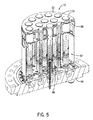
図5に、図4に示した燃料ノズル12の断面を示す。この断面は、ミニ・ノズル・キャップ50内の予混合器チューブ52を示している。図5に示すように、各予混合器チューブ52は、チューブ52の長手軸に沿って設けられた複数の穿孔58を含む。これらの穿孔58によって、窓54および56からの空気が予混合器チューブ52内に送られる。穿孔の数と各穿孔のサイズとは、各予混合器チューブ52内への所望の空気流に基づいて変わっても良い。燃料を、端部カバー38を通して噴射しても良く、穿孔58を通って入る空気と混合しても良い。この場合もやはり、穿孔58の位置、配向、および概略的な配置を、実質的に滞留時間を増加させ、燃料および空気における圧力振動を抑えるように構成しても良い。その結果、次に、燃料ノズル12の下流に設けられた燃焼器16内で起こる燃焼プロセスの振動が実質的に低減する。たとえば、穿孔58の割合は、各予混合器チューブ52の下流部分55よりも上流部分57の方が高くても良い。空気は、より上流側57で穿孔58を通って入るほど、予混合器チューブ52を通って移動する距離は長くなり、一方で、空気は、より下流側55で穿孔58を通って入るほど、予混合器チューブ52を通って移動する距離は短くなる。特定の実施形態においては、穿孔58のサイズを、予混合器チューブ52の上流部分57において比較的大きく取って下流部分55において比較的小さく取っても良いし、逆もまた同様である。たとえば、上流部分57における穿孔58の方が大きい場合、予混合器チューブ52の上流部分57を通って入る空気流の割合が大きくなる場合があり、その結果、予混合器チューブ52における滞留時間が長くなることになる。いくつかの実施形態においては、穿孔58に角度を付けて旋回を誘発して、混合を増やし、滞留時間を長くし、予混合器チューブ52を通って入る空気および燃料流れにおける圧力振動を抑えても良い。最終的には、燃料および空気流における圧力振動が実質的に減衰した後で、予混合器チューブ52から燃料空気混合気を燃焼器16内に噴射して燃焼に備える。
FIG. 5 shows a cross section of the
図6は、図4に示した燃料ノズル12の分解組立図である。この図ではさらに、ミニ・ノズル・キャップ50内の予混合器チューブ52の構成を示している。また図6では、第1の窓54および第2の窓56の別の視野も示している。加えて、この図では、各予混合器チューブ52の基部内へ燃料供給するための経路および構造を例示している。
6 is an exploded view of the
タービン・エンジンは、液体燃料、ガス燃料、または2つの組み合わせで動作しても良い。図6に示す燃料ノズル12は、予混合器チューブ52内への液体およびガス燃料の両方の流れを促進する。しかし他の実施形態では、液体燃料またはガス燃料で単独で動作するように構成しても良い。ガス燃料は、ガス噴射器プレート60を通って予混合器チューブ52に入っても良い。図示したように、このプレート60は、予混合器チューブ52にガスを供給する複数の円錐形オリフィス61を含む。ガスを、端部カバー38を通してガス噴射器プレート60に供給しても良い。端部カバー38は、燃料供給14からのガスをガス噴射器プレート60に送る複数の通路62(たとえば、環状またはアーチ形に成形された凹部)を備えていても良い。例示した実施形態は、3つの通路62、たとえば、第1の通路64、第2の通路66、および第3の通路68を備えている。第2の通路66および第3の通路68は、複数の部分に分割されている。しかし代替的な実施形態では、連続的な環状の通路66および68を用いても良い。通路の数は、燃料ノズル12の構成に基づいて変わっても良い。この図に示すように、ガス・オリフィス61は、中央のオリフィス61を取り囲む2つの同心円で配置されている。この構成では、第1の通路64からガスを中央のオリフィス61に供給しても良く、第2の通路66からガスを内側の円のオリフィス61に供給しても良く、および第3の通路68からガスを外側の円のオリフィス61に供給しても良い。このようにして、ガス燃料を各予混合器チューブ52に供給しても良い。
The turbine engine may operate with liquid fuel, gas fuel, or a combination of the two. The
液体燃料を予混合器チューブ52へ、複数の液体噴霧器スティックまたは液体燃料カートリッジ70を通して供給しても良い。各液体燃料カートリッジ70は、端部カバー38とガス噴射器プレート60とを貫通しても良い。後述するように、各液体燃料カートリッジ70の先端を各ガス・オリフィス61内に配置しても良い。この構成では、液体およびガス燃料の両方とも予混合器チューブ52に入っても良い。たとえば、液体燃料カートリッジ70から、噴霧された液体燃料が各予混合器チューブ52内に噴射されても良い。この噴霧液体は、噴射されたガスおよび空気と予混合器チューブ52内で混合しても良い。混合物を次に、燃料ノズル12を出たときに点火しても良い。さらに、各液体燃料カートリッジ70は、液体スプレイ(たとえば、水スプレイ)を予混合器チューブ52内に噴射するための流体冷媒(たとえば、水)通路を備えていても良い。特定の実施形態においては、予混合器チューブ52の固有の特徴によって、空気、ガス燃料、液体燃料、液体冷媒(たとえば、水)、またはそれらの任意の組み合わせを含む流体供給における圧力変動が実質的に低減される場合がある。たとえば、予混合器チューブ52における穿孔58を、燃焼器16内へ混合物を噴射する前に混合を増加させ、滞留時間を長くして、圧力振動を減衰させるような仕方で、ガス燃料、液体燃料、および/または液体冷媒(たとえば、水)に接触するように、構成しても良い。
Liquid fuel may be supplied to the
図7に、図4に示した燃料ノズル12の断面を示す。前述したように、空気が、ミニ・ノズル・キャップ50に、第1の窓54および第2の窓56を通って入っても良い。この図では、窓54および56を通って穿孔58に至り、穿孔58を通り、予混合器チューブ52に沿って長さ方向に進む空気の経路を示す。第1の窓54から空気がミニ・ノズル・キャップ50の下流部分55内に送られて冷却が促進されることが、空気が予混合器チューブ52内の上流部分57に進む前に行なわれる。言い換えれば、空気流が予混合器チューブ52の外部に沿って上流方向59に下流部分55から上流部分57に進むことが、穿孔58を通って予混合器チューブ52内に入る前に行なわれる。このようにして、空気流59によって、燃料ノズル12、特に予混合器チューブ52が実質的に冷却され、その効果は、燃焼器16における燃焼の高温生成物に最も近い下流部分55における方が大きい。第2の窓56による予混合器チューブ52内への空気流の促進は、予混合器チューブ52の上流部分57において穿孔58内により接近してまたは直接的に行なわれる。図7では、2つの第1の窓54および第2の窓56のみを示している。しかし、図4に最も良く示されるように、これらの窓54および56は、ミニ・ノズル・キャップ50の全周囲に沿って配置しても良い。
FIG. 7 shows a cross section of the
第1の窓54に入った空気をミニ・ノズル・キャップ50の下流部分55に送ることを、ガイドまたは冷却板72を用いて行なっても良い。図7に示すように、燃料ノズル12では、第1の窓54からの空気流を、燃料ノズル12の長手軸と横方向および平行方向の両方向に分配する。すなわち、たとえば、空気流をすべての予混合器チューブ52の周りで横方向に、および穿孔58に向かって上流方向59に長さ方向に分配する。窓54からの空気流59は、最終的には窓56からの空気流と、空気流が予混合器チューブ52における穿孔58を通過するときに混合する。前述したように、窓54からの空気流59によって、燃料ノズル12が下流部分55において実質的に冷却される。その結果、燃焼の高温生成物が下流部分55の付近にあるために、窓54からの空気流59は第2の窓56からの空気流よりも、約50°F〜100°Fだけ暖かい場合がある。したがって、各供給源からの空気を混合することによって、予混合器チューブ52に入る空気温度を下げることに役立つ場合がある。
The air entering the
本実施形態における第1の窓54は、第2の窓56の約2倍の大きさである。この構成によって、ミニ・ノズル・キャップ50の裏面が十分に冷却される一方で、予混合器チューブ52に入る空気温度が下がることが確実になる場合がある。しかし窓サイズ比は、燃料ノズル12の特定のデザイン検討に基づいて変わっても良い。さらに、他の実施形態においてはさらなる窓の組を用いても良い。
The
混合された空気流が、予混合器チューブ52に、チューブ52の穿孔部分74に沿って配置された穿孔58(矢印で示す)を通って入る。前述したように、燃料噴射器から、ガス燃料、液体燃料、液体冷媒(たとえば、水)、またはそれらの組み合わせを予混合器チューブ52内に噴射しても良い。図7に例示した構成では、ガスおよび液体燃料の両方が噴射される。ガスを、端部カバー38における噴射器プレート60の真下に配置された通路62から与えても良い。この実施形態においては、図6に示した同じ3通路構成を用いる。第1の通路64が、中央の予混合器チューブ52の下方に配置されている。第2の通路66が、第1の通路64を同軸または同心の配置で取り囲んで、次の外側の予混合器チューブ52にガスを与える。第3の通路68が、第2の通路66を同軸または同心の配置で取り囲んで、外側の予混合器チューブ52にガスを与える。ガスを予混合器チューブ52内にガス・オリフィス61を通して噴射しても良い。同様に、液体を液体燃料カートリッジ70から噴射しても良い。液体燃料カートリッジ70によって、液体燃料(および任意的な液体冷媒)を、噴霧または液体燃料液滴の形成を誘発するのに十分な圧力で噴射しても良い。液体燃料は、ガス燃料および空気と、予混合器チューブ52の穿孔部分74内で混合する場合がある。燃料と空気とがさらに混合することが、穿孔部分74の下流にある非穿孔部分76において続く場合がある。
The mixed air stream enters the
これら2つの部分74および76を組み合わせることによって、燃料と空気との十分な混合が燃焼前に行なわれることが確実になる場合がある。たとえば、非穿孔部分76によって空気流59がさらに上流に強制的に流れて上流部分57に至る結果、予混合器チューブ52を通るすべての空気流について流路および滞留時間が増加する。上流部分57では、下流側窓54および上流側窓56の両方からの空気流が、穿孔部分74における穿孔58を通った後に、予混合器チューブ52の中を下流方向63に、燃焼器16内へ出るまで移動する。この場合もやはり、非穿孔部分76において穿孔58を排除することは、予混合器チューブ52における空気流の滞留時間を長くするように構成されている。なぜならば、非穿孔部分76によって本質的に、予混合器チューブ52内に空気流が入ることが妨げられ、空気流が上流の穿孔部分74における穿孔58に案内されるからである。さらに、穿孔58の位置が上流にあるため、上流57であるほど燃料空気混合が高まり、その結果、燃焼器16内に噴射する前に燃料と空気とが混合する時間が長くなる。同様に、穿孔58の位置が上流にあるために、流体流れ(たとえば、空気流、ガス流、液体燃料流れ、および液体冷媒流れ)における圧力振動が実質的に減る。なぜならば、穿孔によって横方向の流れが形成されて混合が高まり、圧力を安定させる滞留時間が長くなるからである。
Combining these two
また通路62を通って流れるガス燃料は、液体燃料カートリッジ70を絶縁するとともに、コークス化の可能性が低くなる十分低い値に液体燃料温度が留まることを確実にする働きもする場合がある。コークス化とは、燃料が割れ始めて、カーボン粒子を形成する状態である。これらの粒子は、液体燃料カートリッジ70の内壁に付着する場合がある。時間が経つと、粒子は壁から脱離して液体燃料カートリッジ70の先端を塞ぐ場合がある。コークス化が起こる温度は、燃料に応じて変化する。しかし典型的な液体燃料の場合、コークス化が起こる温度は、約200、220、240、260、または280°Fよりも大きい場合がある。図7に示すように、液体燃料カートリッジ70は、通路62およびガス・オリフィス61内に配置されている。したがって、液体燃料カートリッジ70は、流れるガスによって完全に取り囲まれていても良い。このガスは、液体燃料カートリッジ70内の液体燃料を低温に保って、コークス化が起きる可能性を小さくする働きをする場合がある。
The gaseous fuel flowing through the
燃料および空気が予混合器チューブ52において適切に混合した後で、混合物に点火しても良い。その結果、各予混合器チューブ52の下流部分55の下流において火炎78が生じる。前述したように、火炎78によって燃料ノズル12が加熱される。なぜならば、ミニ・ノズル・キャップ50の下流部分55に比較的近い箇所だからである。したがって、前述したように、第1の窓54からの空気がミニ・ノズル・キャップ50の下流部分55を通って流れて、燃料ノズル12のキャップ50を実質的に冷却する。
After the fuel and air are properly mixed in the
動作中の予混合器チューブ52の数は、所望のタービン・システム出力に基づいて変わっても良い。たとえば、通常動作中に、ミニ・ノズル・キャップ50内のあらゆる予混合器チューブ52が動作して、特定のタービン出力レベルに対して燃料および空気の適切な混合を実現しても良い。しかしタービン・システム10が動作のターンダウン・モードに入るときには、機能している予混合器チューブ52の数は減る場合がある。タービン・エンジンがターンダウンまたは低パワー動作に入るときには、燃焼器16に対する燃料流れは、火炎78が消える点まで減少する場合がある。同様に、低い負荷条件の下では、火炎78の温度が減少して、窒素(NO)および一酸化炭素(CO)の酸化物の排出が増加することになる場合がある。火炎78を維持し、タービン・システム10が許容可能な排出限界内で動作することを確実にするために、燃料ノズル12内で動作する予混合器チューブ52の数は減る場合がある。たとえば、予混合器チューブ52の外輪を、外部の液体燃料カートリッジ70に対する燃料流れを遮断することによって作動停止しても良い。同様に、第3の通路68に対するガス燃料の流れを遮断しても良い。このようにして、動作中の予混合器チューブ52の数を減らしても良い。その結果、残りの予混合器チューブ52が発生させる火炎78を、火炎78が消されず、排出レベルが許容可能なパラメータとなるのを確実にする十分な温度に維持しても良い。
The number of
加えて、各ミニ・ノズル・キャップ50内の予混合器チューブ52の数は、タービン・システム10のデザイン検討に基づいて変わっても良い。たとえば、タービン・システム10が大きくなるほど、各燃料ノズル12内で用いる予混合器チューブ52の数を大きくしても良い。予混合器チューブ52の数は変わっても良い一方で、ミニ・ノズル・キャップ50のサイズおよび形状は各用途に対して同じであっても良い。言い換えれば、タービン・システム10が用いる燃料流量が大きくなるほど、使用するミニ・ノズル・キャップ50が有する予混合器チューブ52の密度は高くなる場合がある。このようにして、タービン・システム10の構造コストが下がる場合がある。なぜならば、各キャップ50内の予混合器チューブ52の数は変わる場合がある一方で、共通のミニ・ノズル・キャップ50をほとんどのタービン・システム10に対して用いても良いからである。この製造方法は、各用途に対して固有の燃料ノズル12をデザインする場合よりも安価である場合がある。
In addition, the number of
図8は、図4の燃料ノズル12において用いても良い予混合器チューブ52の側面図である。図8に示すように、予混合器チューブ52は穿孔部分74と非穿孔部分76とに分割されている。例示した実施形態においては、穿孔部分74は非穿孔部分76の上流に位置している。この構成では、穿孔58内に流れる空気は、燃料噴射器(図示せず)を介して予混合器チューブ52の基部を通って入る燃料と混合しても良い。燃料と空気とを混合したものを次に、非穿孔部分76内に送っても良く、そこで、さらに混合を行なっても良い。
FIG. 8 is a side view of a
空気圧および燃料圧は通常、ガス・タービン・エンジン内で変動する。これらの変動によって、燃焼器振動が特定の周波数において起こる場合がある。この周波数がタービン・エンジン内の一部またはサブシステムの固有周波数に対応していると、その部品またはエンジン全体に対する損傷が生じる場合がある。燃焼器16の混合部分内での空気と燃料との滞留時間を長くすることによって、燃焼器駆動振動が減る場合がある。たとえば、空気圧が時間とともに変動する場合、燃料液滴の滞留時間を長くすると空気圧変動が平均する場合がある。具体的には、液滴が、燃焼前に空気圧変動の少なくとも1つの完全なサイクルを経る場合、その液滴の混合比は、燃料ストリームにおける他の液滴と実質的に同様となる場合がある。実質的に一定の混合比を維持することによって、燃焼器駆動振動が減る場合がある。
Air pressure and fuel pressure typically vary within a gas turbine engine. Due to these variations, combustor oscillations may occur at specific frequencies. If this frequency corresponds to the natural frequency of a part or subsystem in the turbine engine, damage to that part or the entire engine may occur. Increasing the residence time of air and fuel in the mixing portion of the
滞留時間を、燃焼器16の混合部分の長さを延ばすことによって長くしても良い。本実施形態では、燃焼器16の混合部分は予混合器チューブ52に対応する。したがって、予混合器チューブ52が長くなるほど、空気および燃料の両方に対して滞留時間が長くなる。たとえば、各チューブ52の長さと直径との比は、少なくとも、約5、10、15、20、25、30、35、40、45、または50より大きくても良い。
The residence time may be lengthened by extending the length of the mixing portion of the
非穿孔部分76は、さらなる空気と燃料との混合を可能にすることなく、予混合器チューブ52の長さを延ばす働きをする場合がある。この構成では、空気および燃料は、空気が穿孔58を通して噴射された後も混合し続ける場合があり、その結果、燃焼器駆動振動を減らす場合がある。特定の実施形態においては、穿孔部分74の長さは非穿孔部分76の長さに対して、少なくとも、約1.5、2、2.5、3、3.5、4、4.5、5、5.5、6、6.5、7、7.5、8、8.5、9、9.5、または10より大きくても良いし、逆もまた同様である。一実施形態においては、穿孔部分74の長さは予混合器チューブ52の長さの約80%であっても良く、一方で、非穿孔部分76の長さはチューブ52の長さの約20%であっても良い。しかし、これらの部分74および76間での長さの比または割合は、流量および他のデザイン検討に応じて変わっても良い。たとえば、各非穿孔部分76の長さを予混合器チューブ52の長さの約15%〜35%の範囲にして、混合時間を長くし燃焼器駆動振動を減らすようにしても良い。
The
また滞留時間を、予混合器チューブ52を通る流体流れ(たとえば、燃料液滴)の有効な経路長を延ばすことによって長くしても良い。具体的には、空気を予混合器チューブ52内に旋回運動で噴射しても良い。この旋回運動によって、液滴が予混合器チューブ52の中を非直線経路(たとえば、ランダム経路または螺旋状経路)に沿って移動することが誘発される場合があり、その結果、効果的に液滴経路長が長くなる。旋回の量は所望の滞留時間に基づいて変わっても良い。
The residence time may also be increased by extending the effective path length of the fluid flow (eg, fuel droplets) through the
また半径流の旋回は、液体燃料液滴を予混合器チューブ52の内壁に寄せ付けない働きをする場合がある。液滴は壁に付着すると、チューブ52内に残る時間が長くなる場合があり、燃焼を遅らせることになる。したがって、液滴が適切に予混合器チューブ52を出ることを確実にすることによって、タービン・システム10の効率が増加する場合がある。
Further, the swirling of the radial flow may function to keep the liquid fuel droplets away from the inner wall of the
加えて、予混合器チューブ52内での旋回空気によって、液体燃料液滴の噴霧が改善される場合がある。旋回空気によって、液滴の形成が促進されるとともに、液滴が予混合器チューブ52の全体に渡って概ね一様に分散する場合がある。その結果、タービン・システム10の効率がさらに向上する場合がある。
In addition, swirling air in the
前述したように、空気が予混合器チューブ52に穿孔58を通って入っても良い。これらの穿孔58は、予混合器チューブ52の長さに沿った異なる軸方向位置における一連の同心円で配置しても良い。特定の実施形態においては、各同心円は24個の穿孔を有していても良く、各穿孔の直径は約0.05インチである。穿孔の数およびサイズ58は変わっても良い。たとえば、予混合器チューブ52は、空気の貫通および混合を強化するように構成された大きな液滴状の穿孔77を備えていても良い。加えて、中間サイズのスロットが付けられた穿孔79を予混合器チューブ52の下流端の方に配置して、高程度の旋回が発生するようにしても良い。穿孔58を、予混合器チューブ52の長手軸に垂直な平面に沿って角度を付けても良い。角度の付いた穿孔58によって旋回が誘発される場合があり、旋回の大きさは各穿孔58の角度に依存する場合がある。
As described above, air may enter the
図9、10、および11は、図8の線分9−9、10−10、および11−11に沿って見た予混合器チューブ52の単純化した断面図であり、チューブ52の長さに沿った異なる軸方向位置における穿孔58の角度の付いた配向をさらに例示するものである。たとえば、図9に、穿孔58と半径方向軸81との間の角度80を例示する。同様に、図10に、穿孔58と半径方向軸83との間の角度82を例示する。角度80および82の範囲は、約0〜90度、0〜60度、0〜45度、0〜30度、または0〜15度であっても良い。さらなる例として、角度80および82は、約5、10、15、20、25、30、35、40、もしくは45度、またはそれらの間の任意の角度であっても良い。
9, 10 and 11 are simplified cross-sectional views of the
特定の実施形態においては、穿孔58の角度は、線分9−9、10−10、および11−11によって表わされる各軸方向位置ならびにチューブ52の長さに沿った他の軸方向位置において、同じであっても良い。しかし、例示した実施形態においては、穿孔58の角度はチューブ52の長さに沿って変わっても良い。たとえば、角度は徐々に増加しても良いし、減少しても良いし、方向が交互に変わっても良いし、またはそれらの組み合わせであっても良い。たとえば、図9に示す穿孔58の角度80は、図10に示す穿孔58の角度82よりも大きい。したがって、図9の穿孔58によって誘発される旋回の程度は、図10の穿孔58によって誘発される旋回の程度よりも大きい場合がある。
In certain embodiments, the angle of the
旋回の程度は、予混合器チューブ52の穿孔部分74の長さに沿って変わっても良い。図8に示す予混合器チューブ52は、穿孔部分74の下方の部分では旋回はなく、中央の部分では中程度の量の旋回であり、上方の部分では高程度の旋回である。これらの旋回の程度が、図11、10、および9において、それぞれ見られる場合がある。この実施形態においては、旋回の程度は、燃料が予混合器チューブ52を通って下流方向に流れるにつれて増加する。
The degree of swirl may vary along the length of the perforated
他の実施形態においては、旋回の程度は予混合器チューブ52の長さに沿って減少しても良い。さらなる実施形態においては、予混合器チューブ52のある部分が空気をある方向に旋回させても良く、一方で、他の部分が空気を実質的に反対方向に旋回させても良い。同様に、旋回の程度および旋回の方向が両方とも、予混合器チューブ52の長さに沿って変わっても良い。
In other embodiments, the degree of swirl may decrease along the length of the
さらに別の実施形態においては、空気を半径方向および軸方向の両方向に送っても良い。たとえば、穿孔58によって予混合器チューブ52内に合成角が形成されても良い。言い換えれば、穿孔58は半径方向および軸方向の両方向において角度が付いていても良い。たとえば、軸角(すなわち、穿孔58と長手軸84との間の角度)の範囲は、約0〜90度、0〜60度、0〜45度、0〜30度、または0〜15度であっても良い。さらなる例として、軸角は、約5、10、15、20、25、30、35、40、もしくは45度、またはそれらの間の任意の角度であっても良い。合成角が付いた穿孔58によって、空気が、予混合器チューブ52の長手軸に垂直な平面内で旋回することと、軸方向に流れることとが誘発される場合がある。空気を、燃料流れ方向の下流に送っても良いし、上流に送っても良い。下流流れによって噴霧が向上する場合があり、一方で、上流流れによって燃料および空気のより良好な混合が実現される場合がある。空気流の軸方向成分の大きさおよび方向は、予混合器チューブ52の長さに沿った軸方向位置に基づいて変わっても良い。
In yet another embodiment, air may be sent in both the radial and axial directions. For example, a composite angle may be formed in the
この書面の説明では、例を用いて、ベスト・モードを含む本発明を開示するとともに、どんな当業者も本発明を実行できるように、たとえば任意の装置またはシステムを作りおよび用いること、ならびに取り入れられた任意の方法を行なうことができるようにしている。本発明の特許可能な範囲は、請求項によって規定されるとともに、当業者に想起される他の例を含んでいても良い。このような他の例は、請求項の文字通りの言葉使いと違わない構造要素を有するか、または請求項の文字通りの言葉使いとの差が非実質的である均等な構造要素を含む場合には、請求項の範囲内であることが意図されている。 This written description uses examples to disclose the invention, including the best mode, and to allow any person skilled in the art to practice and use the invention, for example, to make and use any device or system. Any way you can do it. The patentable scope of the invention is defined by the claims, and may include other examples that occur to those skilled in the art. Such other examples include structural elements that do not differ from the literal wording of the claim, or include equivalent structural elements that are insubstantial to the literal wording of the claim. It is intended to be within the scope of the claims.
Claims (11)
前記燃料ノズル(12)は、
燃料流れを出力するように構成された燃料噴射器(61、70)と、
燃料噴射器(61、70)から出力される燃料流れの周囲に配置される複数の予混合器チューブ(52)であって、穿孔部分(74)と非穿孔部分(76)とを有する側面を備え、非穿孔部分(76)は穿孔部分(74)の下流にある複数の予混合器チューブ(52)と、
燃料噴射器(61、70)と複数の予混合器チューブ(52)とを取り囲むキャップ(50)と、
を備え、
キャップ(50)は、複数の窓を備える側部と、複数の開口を備える端部を有し、複数の開口の各々に予混合器チューブ(52)の下流側の端が接続し、
キャップ(50)は、燃焼器(16)のケーシング(40)内に配置され、複数の窓から空気を受け取り、空気をキャップ(50)内面の下流部分(55)及び、複数の予混合器チューブ(52)の下流部分に送って燃料噴射器(61、70)の下流部分の冷却を促進し、冷却に使用された空気を複数の予混合器チューブ(52)の上流部分に送るように構成されている、システム(10)。 A fuel nozzle (12),
The fuel nozzle (12)
A fuel injector (61, 70) configured to output a fuel flow;
A plurality of premixer tubes (52) disposed around a fuel flow output from a fuel injector (61, 70) having a side surface having a perforated portion (74) and a non-perforated portion (76). A non-perforated portion (76) comprising a plurality of premixer tubes (52) downstream of the perforated portion (74);
A cap (50) surrounding the fuel injector (61, 70) and the plurality of premixer tubes (52);
With
The cap (50) has a side portion having a plurality of windows and an end portion having a plurality of openings, and a downstream end of the premixer tube (52) is connected to each of the plurality of openings,
The cap (50) is disposed within the casing (40) of the combustor (16) and receives air from a plurality of windows, and the air is downstream of the inner surface of the cap (50) (55) and a plurality of premixer tubes. (52) sent to the downstream portion to facilitate cooling of the downstream portion of the fuel injector (61, 70) and configured to send the air used for cooling to the upstream portion of the plurality of premixer tubes (52) A system (10).
前記燃料ノズル(12)は、
燃料流れを出力するように構成された燃料噴射器(61、70)と、
燃料噴射器(61、70)の下流において燃料流れの周囲に配置された穿孔(58)を有する側面を備える穿孔された複数の予混合器チューブ(52)であって、穿孔(58)は、空気流が穿孔された複数の予混合器チューブ(52)内に旋回運動で入っていくことを促進するように角度が付いており、旋回の程度は、穿孔された複数の予混合器チューブ(52)の長さに沿った穿孔(58)の軸方向位置に基づいて変化する、複数の予混合器チューブ(52)と、
燃料噴射器(61、70)と複数の予混合器チューブ(52)とを取り囲むキャップ(50)と、
を備え、
キャップ(50)は、複数の窓を備える側部と、複数の開口を備える端部を有し、複数の開口の各々に予混合器チューブ(52)の下流側の端が接続し、
キャップ(50)は、燃焼器(16)のケーシング(40)内に配置され、複数の窓から空気を受け取り、空気をキャップ(50)内面の下流部分(55)及び、複数の予混合器チューブ(52)の下流部分に送って燃料噴射器(61、70)の下流部分の冷却を促進し、冷却に使用された空気を複数の予混合器チューブ(52)の上流部分に送るように構成されている、システム(10)。 A fuel nozzle (12),
The fuel nozzle (12)
A fuel injector (61, 70) configured to output a fuel flow;
A plurality of perforated premixer tubes (52) with sides having perforations (58) disposed around the fuel flow downstream of the fuel injectors (61, 70), wherein the perforations (58) are and angled so as to facilitate the air flow entering in swirling motion in a plurality of premixer tubes perforated (52), the degree of swirl, perforated plurality of premixer tubes ( A plurality of premixer tubes (52) that vary based on the axial position of the perforations (58) along the length of 52);
A cap (50) surrounding the fuel injector (61, 70) and the plurality of premixer tubes (52);
With
The cap (50) has a side portion having a plurality of windows and an end portion having a plurality of openings, and a downstream end of the premixer tube (52) is connected to each of the plurality of openings,
The cap (50) is disposed within the casing (40) of the combustor (16) and receives air from a plurality of windows, and the air is downstream of the inner surface of the cap (50) (55) and a plurality of premixer tubes. (52) sent to the downstream portion to facilitate cooling of the downstream portion of the fuel injector (61, 70) and configured to send the air used for cooling to the upstream portion of the plurality of premixer tubes (52) A system (10).
旋回の程度は、予混合器チューブ(52)の長さに沿った軸方向位置とともに変化する請求項1に記載のシステム(10)。 The perforations (58) of the perforated portion (74) are configured to swirl the air entering the premixer tube (52) ;
The system (10) of claim 1 , wherein the degree of swirl varies with axial position along the length of the premixer tube (52).
燃料噴射器(61、70)は、燃料カートリッジ(70)を通して予混合器チューブ(52)に燃料を供給する複数のオリフィス(61)を含むガス噴射器プレート(60)を備える請求項1乃至4のいずれかに記載のシステム(10)。 Comprising a fuel nozzle (12) end cover is attached (38), a fuel nozzle (12) and a combustor having a (16),
Fuel injector (61,70), the fuel cartridge (70) according to claim 1 or Ru with a plurality of orifices the gas injector plate (60) including (61) for supplying fuel to the premixer tube (52) through The system (10) according to any one of claims 4 to 10.
複数の窓(54)に入った空気をキャップ(50)の下流部分(55)に送ること促進する冷却板(72)とを備える請求項1乃至9のいずれかに記載のシステム(10)。The system (10) according to any of the preceding claims, comprising a cold plate (72) that facilitates sending air entering the plurality of windows (54) to a downstream portion (55) of the cap (50).
燃料を供給する複数のオリフィス(61)を含むガス噴射器プレート(60)を提供する工程と、Providing a gas injector plate (60) including a plurality of orifices (61) for supplying fuel;
複数のオリフィス(61)の各々の周囲に予混合器チューブ(52)を配置する工程と、Placing a premixer tube (52) around each of the plurality of orifices (61);
キャップ(50)が、燃料噴射器(61、70)と予混合器チューブ(52)とを取り囲み、キャップ(50)の複数の開口の各々に予混合器チューブ(52)の下流側の端が接続するように、キャップ(50)を端部カバー(38)に固定する工程と、A cap (50) surrounds the fuel injector (61, 70) and the premixer tube (52), and a downstream end of the premixer tube (52) is located in each of the plurality of openings of the cap (50). Securing the cap (50) to the end cover (38) to connect;
を含む方法。Including methods.
Applications Claiming Priority (2)
| Application Number | Priority Date | Filing Date | Title |
|---|---|---|---|
| US12/364,488 | 2009-02-02 | ||
| US12/364,488 US8205452B2 (en) | 2009-02-02 | 2009-02-02 | Apparatus for fuel injection in a turbine engine |
Publications (3)
| Publication Number | Publication Date |
|---|---|
| JP2010175244A JP2010175244A (en) | 2010-08-12 |
| JP2010175244A5 JP2010175244A5 (en) | 2012-09-27 |
| JP5179525B2 true JP5179525B2 (en) | 2013-04-10 |
Family
ID=41666733
Family Applications (1)
| Application Number | Title | Priority Date | Filing Date |
|---|---|---|---|
| JP2010015315A Active JP5179525B2 (en) | 2009-02-02 | 2010-01-27 | Equipment for fuel injection in turbine engines |
Country Status (4)
| Country | Link |
|---|---|
| US (1) | US8205452B2 (en) |
| EP (1) | EP2213944B1 (en) |
| JP (1) | JP5179525B2 (en) |
| CN (1) | CN101818908B (en) |
Families Citing this family (64)
| Publication number | Priority date | Publication date | Assignee | Title |
|---|---|---|---|---|
| US9140454B2 (en) * | 2009-01-23 | 2015-09-22 | General Electric Company | Bundled multi-tube nozzle for a turbomachine |
| US8539773B2 (en) * | 2009-02-04 | 2013-09-24 | General Electric Company | Premixed direct injection nozzle for highly reactive fuels |
| US8365533B2 (en) * | 2009-09-22 | 2013-02-05 | General Electric Company | Universal multi-nozzle combustion system and method |
| US8683804B2 (en) * | 2009-11-13 | 2014-04-01 | General Electric Company | Premixing apparatus for fuel injection in a turbine engine |
| US8511092B2 (en) * | 2010-08-13 | 2013-08-20 | General Electric Company | Dimpled/grooved face on a fuel injection nozzle body for flame stabilization and related method |
| US8925324B2 (en) | 2010-10-05 | 2015-01-06 | General Electric Company | Turbomachine including a mixing tube element having a vortex generator |
| US9360219B2 (en) * | 2010-12-30 | 2016-06-07 | Rolls-Royce North American Technologies, Inc. | Supercritical or mixed phase multi-port fuel injector |
| US8984887B2 (en) * | 2011-09-25 | 2015-03-24 | General Electric Company | Combustor and method for supplying fuel to a combustor |
| US8894407B2 (en) * | 2011-11-11 | 2014-11-25 | General Electric Company | Combustor and method for supplying fuel to a combustor |
| US9188340B2 (en) * | 2011-11-18 | 2015-11-17 | General Electric Company | Gas turbine combustor endcover with adjustable flow restrictor and related method |
| US9719685B2 (en) | 2011-12-20 | 2017-08-01 | General Electric Company | System and method for flame stabilization |
| US9366440B2 (en) * | 2012-01-04 | 2016-06-14 | General Electric Company | Fuel nozzles with mixing tubes surrounding a liquid fuel cartridge for injecting fuel in a gas turbine combustor |
| US20130192234A1 (en) * | 2012-01-26 | 2013-08-01 | General Electric Company | Bundled multi-tube nozzle assembly |
| US20130227928A1 (en) * | 2012-03-01 | 2013-09-05 | Jong Ho Uhm | Fuel nozzle assembly for use in turbine engines and method of assembling same |
| US9151500B2 (en) | 2012-03-15 | 2015-10-06 | General Electric Company | System for supplying a fuel and a working fluid through a liner to a combustion chamber |
| US9163839B2 (en) * | 2012-03-19 | 2015-10-20 | General Electric Company | Micromixer combustion head end assembly |
| WO2013147632A1 (en) * | 2012-03-29 | 2013-10-03 | General Electric Company | Bi-directional end cover with extraction capability for gas turbine combustor |
| US9284888B2 (en) * | 2012-04-25 | 2016-03-15 | General Electric Company | System for supplying fuel to late-lean fuel injectors of a combustor |
| US20130283802A1 (en) * | 2012-04-27 | 2013-10-31 | General Electric Company | Combustor |
| US9261279B2 (en) * | 2012-05-25 | 2016-02-16 | General Electric Company | Liquid cartridge with passively fueled premixed air blast circuit for gas operation |
| US9267690B2 (en) | 2012-05-29 | 2016-02-23 | General Electric Company | Turbomachine combustor nozzle including a monolithic nozzle component and method of forming the same |
| DE102012216080A1 (en) | 2012-08-17 | 2014-02-20 | Dürr Systems GmbH | burner |
| US9285121B2 (en) * | 2012-08-23 | 2016-03-15 | General Electric Company | Gas turbine cooling circuit including a seal for a perforated plate |
| US9677766B2 (en) * | 2012-11-28 | 2017-06-13 | General Electric Company | Fuel nozzle for use in a turbine engine and method of assembly |
| US9599343B2 (en) | 2012-11-28 | 2017-03-21 | General Electric Company | Fuel nozzle for use in a turbine engine and method of assembly |
| EP2746665B1 (en) * | 2012-12-19 | 2019-06-19 | General Electric Company | Fuel distribution and mixing plate |
| US9366437B2 (en) * | 2012-12-20 | 2016-06-14 | General Electric Company | System for reducing flame holding within a combustor |
| US9151503B2 (en) * | 2013-01-04 | 2015-10-06 | General Electric Company | Coaxial fuel supply for a micromixer |
| US9366439B2 (en) * | 2013-03-12 | 2016-06-14 | General Electric Company | Combustor end cover with fuel plenums |
| US9759425B2 (en) | 2013-03-12 | 2017-09-12 | General Electric Company | System and method having multi-tube fuel nozzle with multiple fuel injectors |
| US9650959B2 (en) * | 2013-03-12 | 2017-05-16 | General Electric Company | Fuel-air mixing system with mixing chambers of various lengths for gas turbine system |
| US9671112B2 (en) | 2013-03-12 | 2017-06-06 | General Electric Company | Air diffuser for a head end of a combustor |
| US9651259B2 (en) | 2013-03-12 | 2017-05-16 | General Electric Company | Multi-injector micromixing system |
| US9765973B2 (en) | 2013-03-12 | 2017-09-19 | General Electric Company | System and method for tube level air flow conditioning |
| US20140338340A1 (en) * | 2013-03-12 | 2014-11-20 | General Electric Company | System and method for tube level air flow conditioning |
| US9528444B2 (en) | 2013-03-12 | 2016-12-27 | General Electric Company | System having multi-tube fuel nozzle with floating arrangement of mixing tubes |
| US9347668B2 (en) * | 2013-03-12 | 2016-05-24 | General Electric Company | End cover configuration and assembly |
| US9534787B2 (en) | 2013-03-12 | 2017-01-03 | General Electric Company | Micromixing cap assembly |
| US9322555B2 (en) * | 2013-07-01 | 2016-04-26 | General Electric Company | Cap assembly for a bundled tube fuel injector |
| US9371997B2 (en) * | 2013-07-01 | 2016-06-21 | General Electric Company | System for supporting a bundled tube fuel injector within a combustor |
| WO2015040228A1 (en) * | 2013-09-23 | 2015-03-26 | Siemens Aktiengesellschaft | Burner for a gas turbine and method for reducing thermo-acoustic oscillations in a gas turbine |
| US20150107255A1 (en) * | 2013-10-18 | 2015-04-23 | General Electric Company | Turbomachine combustor having an externally fueled late lean injection (lli) system |
| US20150159877A1 (en) * | 2013-12-06 | 2015-06-11 | General Electric Company | Late lean injection manifold mixing system |
| US9664392B2 (en) * | 2013-12-13 | 2017-05-30 | General Electric Company | Bundled tube fuel injector with outer shroud and outer band connection |
| US9625157B2 (en) | 2014-02-12 | 2017-04-18 | General Electric Company | Combustor cap assembly |
| US9528704B2 (en) * | 2014-02-21 | 2016-12-27 | General Electric Company | Combustor cap having non-round outlets for mixing tubes |
| US9528702B2 (en) * | 2014-02-21 | 2016-12-27 | General Electric Company | System having a combustor cap |
| US20150285502A1 (en) * | 2014-04-08 | 2015-10-08 | General Electric Company | Fuel nozzle shroud and method of manufacturing the shroud |
| EP2980482A1 (en) * | 2014-07-30 | 2016-02-03 | Siemens Aktiengesellschaft | Burner for a combustion engine and combustion engine |
| US10094566B2 (en) * | 2015-02-04 | 2018-10-09 | General Electric Company | Systems and methods for high volumetric oxidant flow in gas turbine engine with exhaust gas recirculation |
| JP6535525B2 (en) * | 2015-07-01 | 2019-06-26 | 三菱日立パワーシステムズ株式会社 | Gas turbine combustor |
| US11428413B2 (en) * | 2016-03-25 | 2022-08-30 | General Electric Company | Fuel injection module for segmented annular combustion system |
| US10570826B2 (en) * | 2017-09-25 | 2020-02-25 | Delavan Inc. | Fuel manifold with nested annular passages and radially extending channels |
| US11466620B2 (en) * | 2017-10-20 | 2022-10-11 | Siemens Energy, Inc. | Hybrid manufacturing of a support housing |
| CN108278634B (en) * | 2017-12-06 | 2020-07-14 | 中国联合重型燃气轮机技术有限公司 | Gas turbine and combustor thereof |
| US10767866B2 (en) * | 2018-07-11 | 2020-09-08 | General Electric Company | Micromixer for use with liquid fuel |
| CN111043627A (en) * | 2019-12-31 | 2020-04-21 | 新奥能源动力科技(上海)有限公司 | Combustion chamber structure and micro gas turbine |
| JP7344177B2 (en) | 2020-06-09 | 2023-09-13 | 株式会社三井E&S | Gas turbine combustion control method |
| CN113028449B (en) * | 2021-02-26 | 2023-03-17 | 中国空气动力研究与发展中心设备设计与测试技术研究所 | Streamline fuel flow distribution disc of fuel gas generator |
| US11692709B2 (en) * | 2021-03-11 | 2023-07-04 | General Electric Company | Gas turbine fuel mixer comprising a plurality of mini tubes for generating a fuel-air mixture |
| US11639795B2 (en) | 2021-05-14 | 2023-05-02 | Pratt & Whitney Canada Corp. | Tapered fuel gallery for a fuel nozzle |
| CN116147016A (en) | 2021-11-22 | 2023-05-23 | 通用电气公司 | Ferrule for fuel-air mixer assembly |
| US11828465B2 (en) * | 2022-01-21 | 2023-11-28 | General Electric Company | Combustor fuel assembly |
| US20230266003A1 (en) * | 2022-02-22 | 2023-08-24 | Honeywell International Inc. | Ultra-low nox multi-port burner apparatus |
Family Cites Families (14)
| Publication number | Priority date | Publication date | Assignee | Title |
|---|---|---|---|---|
| US4100733A (en) * | 1976-10-04 | 1978-07-18 | United Technologies Corporation | Premix combustor |
| JPH05196232A (en) * | 1991-08-01 | 1993-08-06 | General Electric Co <Ge> | Back fire-resistant fuel staging type premixed combustion apparatus |
| US5235814A (en) * | 1991-08-01 | 1993-08-17 | General Electric Company | Flashback resistant fuel staged premixed combustor |
| JPH0814565A (en) * | 1994-04-28 | 1996-01-19 | Hitachi Ltd | Gas turbine combustor |
| US5611684A (en) * | 1995-04-10 | 1997-03-18 | Eclipse, Inc. | Fuel-air mixing unit |
| US5778676A (en) * | 1996-01-02 | 1998-07-14 | General Electric Company | Dual fuel mixer for gas turbine combustor |
| US5850732A (en) * | 1997-05-13 | 1998-12-22 | Capstone Turbine Corporation | Low emissions combustion system for a gas turbine engine |
| US6141954A (en) * | 1998-05-18 | 2000-11-07 | United Technologies Corporation | Premixing fuel injector with improved flame disgorgement capacity |
| EP1036988A3 (en) * | 1999-02-26 | 2001-05-16 | R. Jan Mowill | Gas turbine engine fuel/air premixers with variable geometry exit and method for controlling exit velocities |
| GB9929601D0 (en) * | 1999-12-16 | 2000-02-09 | Rolls Royce Plc | A combustion chamber |
| US6427446B1 (en) * | 2000-09-19 | 2002-08-06 | Power Systems Mfg., Llc | Low NOx emission combustion liner with circumferentially angled film cooling holes |
| JP4566608B2 (en) * | 2004-04-12 | 2010-10-20 | 新潟原動機株式会社 | Fuel injection nozzle of gas turbine engine for digestion gas |
| JP4626251B2 (en) * | 2004-10-06 | 2011-02-02 | 株式会社日立製作所 | Combustor and combustion method of combustor |
| US7779636B2 (en) * | 2005-05-04 | 2010-08-24 | Delavan Inc | Lean direct injection atomizer for gas turbine engines |
-
2009
- 2009-02-02 US US12/364,488 patent/US8205452B2/en active Active
-
2010
- 2010-01-27 JP JP2010015315A patent/JP5179525B2/en active Active
- 2010-01-29 EP EP10152191.2A patent/EP2213944B1/en active Active
- 2010-02-02 CN CN2010101210780A patent/CN101818908B/en active Active
Also Published As
| Publication number | Publication date |
|---|---|
| EP2213944B1 (en) | 2019-01-16 |
| JP2010175244A (en) | 2010-08-12 |
| EP2213944A3 (en) | 2018-01-03 |
| EP2213944A2 (en) | 2010-08-04 |
| CN101818908B (en) | 2013-09-25 |
| US20100192579A1 (en) | 2010-08-05 |
| US8205452B2 (en) | 2012-06-26 |
| CN101818908A (en) | 2010-09-01 |
Similar Documents
| Publication | Publication Date | Title |
|---|---|---|
| JP5179525B2 (en) | Equipment for fuel injection in turbine engines | |
| US8683804B2 (en) | Premixing apparatus for fuel injection in a turbine engine | |
| JP6401463B2 (en) | System and method for air flow regulation at tube level | |
| US20110016866A1 (en) | Apparatus for fuel injection in a turbine engine | |
| JP6035021B2 (en) | Dual orifice fuel nozzle with improved fuel atomization | |
| US7065972B2 (en) | Fuel-air mixing apparatus for reducing gas turbine combustor exhaust emissions | |
| JP6557463B2 (en) | Fuel injector with premixed pilot nozzle | |
| CN108019775B (en) | Compact hybrid fuel nozzle assembly with mixing sleeve | |
| EP2618060B1 (en) | Axial flow fuel nozzle with a stepped center body | |
| JP6196868B2 (en) | Fuel nozzle and its assembly method | |
| JP5378934B2 (en) | System and method for air-fuel mixing in a gas turbine | |
| US20150253011A1 (en) | Annular premixed pilot in fuel nozzle | |
| US20100263382A1 (en) | Dual orifice pilot fuel injector | |
| JP2011232023A (en) | Pocketed air, and fuel mixing tube | |
| JP2008089298A (en) | Function enhancement with liquid fuel for natural gas swirl stabilized nozzle and method | |
| JP2012132672A (en) | Cooling flowpath dirt deflector in fuel nozzle | |
| EP2092240A1 (en) | Fuel injector | |
| EP2873922B1 (en) | Gas turbine combustor | |
| JP2008128631A (en) | Device for injecting fuel-air mixture, combustion chamber and turbomachine equipped with such device | |
| KR101752114B1 (en) | Nozzle, combustion apparatus, and gas turbine | |
| JP2015105821A (en) | Premixer assembly for mixing fuel and air for combustion | |
| JP2016538454A (en) | Liquid fuel cartridge for fuel nozzle | |
| RU2533609C2 (en) | Burner flame stabilisation | |
| KR100760557B1 (en) | Improved liquid fuel injector for burners of gas turbines | |
| WO2020259918A1 (en) | Combustor for a gas turbine |
Legal Events
| Date | Code | Title | Description |
|---|---|---|---|
| A521 | Request for written amendment filed |
Free format text: JAPANESE INTERMEDIATE CODE: A523 Effective date: 20120813 |
|
| A621 | Written request for application examination |
Free format text: JAPANESE INTERMEDIATE CODE: A621 Effective date: 20120813 |
|
| A871 | Explanation of circumstances concerning accelerated examination |
Free format text: JAPANESE INTERMEDIATE CODE: A871 Effective date: 20120813 |
|
| A975 | Report on accelerated examination |
Free format text: JAPANESE INTERMEDIATE CODE: A971005 Effective date: 20120904 |
|
| A131 | Notification of reasons for refusal |
Free format text: JAPANESE INTERMEDIATE CODE: A131 Effective date: 20120911 |
|
| A521 | Request for written amendment filed |
Free format text: JAPANESE INTERMEDIATE CODE: A523 Effective date: 20121022 |
|
| TRDD | Decision of grant or rejection written | ||
| A01 | Written decision to grant a patent or to grant a registration (utility model) |
Free format text: JAPANESE INTERMEDIATE CODE: A01 Effective date: 20121218 |
|
| A61 | First payment of annual fees (during grant procedure) |
Free format text: JAPANESE INTERMEDIATE CODE: A61 Effective date: 20130109 |
|
| R150 | Certificate of patent or registration of utility model |
Ref document number: 5179525 Country of ref document: JP Free format text: JAPANESE INTERMEDIATE CODE: R150 |
|
| R250 | Receipt of annual fees |
Free format text: JAPANESE INTERMEDIATE CODE: R250 |
|
| R250 | Receipt of annual fees |
Free format text: JAPANESE INTERMEDIATE CODE: R250 |
|
| R250 | Receipt of annual fees |
Free format text: JAPANESE INTERMEDIATE CODE: R250 |
|
| R250 | Receipt of annual fees |
Free format text: JAPANESE INTERMEDIATE CODE: R250 |
|
| R250 | Receipt of annual fees |
Free format text: JAPANESE INTERMEDIATE CODE: R250 |
|
| R250 | Receipt of annual fees |
Free format text: JAPANESE INTERMEDIATE CODE: R250 |
|
| R250 | Receipt of annual fees |
Free format text: JAPANESE INTERMEDIATE CODE: R250 |
|
| R250 | Receipt of annual fees |
Free format text: JAPANESE INTERMEDIATE CODE: R250 |
|
| S111 | Request for change of ownership or part of ownership |
Free format text: JAPANESE INTERMEDIATE CODE: R313113 |
|
| R350 | Written notification of registration of transfer |
Free format text: JAPANESE INTERMEDIATE CODE: R350 |
|
| R250 | Receipt of annual fees |
Free format text: JAPANESE INTERMEDIATE CODE: R250 |