JP5179057B2 - Respirator with instrument introduction compartment and manifold - Google Patents
Respirator with instrument introduction compartment and manifold Download PDFInfo
- Publication number
- JP5179057B2 JP5179057B2 JP2006532261A JP2006532261A JP5179057B2 JP 5179057 B2 JP5179057 B2 JP 5179057B2 JP 2006532261 A JP2006532261 A JP 2006532261A JP 2006532261 A JP2006532261 A JP 2006532261A JP 5179057 B2 JP5179057 B2 JP 5179057B2
- Authority
- JP
- Japan
- Prior art keywords
- instrument
- introduction section
- opening
- instrument introduction
- manifold
- Prior art date
- Legal status (The legal status is an assumption and is not a legal conclusion. Google has not performed a legal analysis and makes no representation as to the accuracy of the status listed.)
- Expired - Lifetime
Links
- 230000000241 respiratory effect Effects 0.000 claims description 89
- 238000004140 cleaning Methods 0.000 claims description 52
- 230000029058 respiratory gaseous exchange Effects 0.000 claims description 46
- 238000003973 irrigation Methods 0.000 claims description 22
- 230000002262 irrigation Effects 0.000 claims description 22
- 238000004891 communication Methods 0.000 claims description 15
- 239000012530 fluid Substances 0.000 claims description 9
- 238000003780 insertion Methods 0.000 claims description 9
- 230000037431 insertion Effects 0.000 claims description 9
- 238000012546 transfer Methods 0.000 claims description 3
- 230000000903 blocking effect Effects 0.000 claims 2
- 230000028327 secretion Effects 0.000 description 24
- 238000000034 method Methods 0.000 description 8
- 238000011109 contamination Methods 0.000 description 5
- 244000052769 pathogen Species 0.000 description 5
- 210000002345 respiratory system Anatomy 0.000 description 5
- 239000007788 liquid Substances 0.000 description 4
- 210000004072 lung Anatomy 0.000 description 4
- 210000003097 mucus Anatomy 0.000 description 4
- 238000009423 ventilation Methods 0.000 description 4
- 230000008901 benefit Effects 0.000 description 3
- 230000002452 interceptive effect Effects 0.000 description 3
- 230000007246 mechanism Effects 0.000 description 3
- 229940113601 irrigation solution Drugs 0.000 description 2
- 238000012986 modification Methods 0.000 description 2
- 230000004048 modification Effects 0.000 description 2
- 230000001681 protective effect Effects 0.000 description 2
- 239000000853 adhesive Substances 0.000 description 1
- 230000001070 adhesive effect Effects 0.000 description 1
- 230000000712 assembly Effects 0.000 description 1
- 238000000429 assembly Methods 0.000 description 1
- QVGXLLKOCUKJST-UHFFFAOYSA-N atomic oxygen Chemical compound [O] QVGXLLKOCUKJST-UHFFFAOYSA-N 0.000 description 1
- 238000005452 bending Methods 0.000 description 1
- 230000009286 beneficial effect Effects 0.000 description 1
- 238000009395 breeding Methods 0.000 description 1
- 230000001488 breeding effect Effects 0.000 description 1
- 230000008878 coupling Effects 0.000 description 1
- 238000010168 coupling process Methods 0.000 description 1
- 238000005859 coupling reaction Methods 0.000 description 1
- 229920002457 flexible plastic Polymers 0.000 description 1
- 210000000987 immune system Anatomy 0.000 description 1
- 208000015181 infectious disease Diseases 0.000 description 1
- 238000001802 infusion Methods 0.000 description 1
- 230000007774 longterm Effects 0.000 description 1
- 229910052760 oxygen Inorganic materials 0.000 description 1
- 239000001301 oxygen Substances 0.000 description 1
- 238000006213 oxygenation reaction Methods 0.000 description 1
- 230000008569 process Effects 0.000 description 1
- 230000009467 reduction Effects 0.000 description 1
- 230000000717 retained effect Effects 0.000 description 1
- 238000001356 surgical procedure Methods 0.000 description 1
- 238000002560 therapeutic procedure Methods 0.000 description 1
- 238000003466 welding Methods 0.000 description 1
Images


Classifications
-
- A—HUMAN NECESSITIES
- A61—MEDICAL OR VETERINARY SCIENCE; HYGIENE
- A61M—DEVICES FOR INTRODUCING MEDIA INTO, OR ONTO, THE BODY; DEVICES FOR TRANSDUCING BODY MEDIA OR FOR TAKING MEDIA FROM THE BODY; DEVICES FOR PRODUCING OR ENDING SLEEP OR STUPOR
- A61M16/00—Devices for influencing the respiratory system of patients by gas treatment, e.g. mouth-to-mouth respiration; Tracheal tubes
- A61M16/04—Tracheal tubes
- A61M16/0463—Tracheal tubes combined with suction tubes, catheters or the like; Outside connections
-
- A—HUMAN NECESSITIES
- A61—MEDICAL OR VETERINARY SCIENCE; HYGIENE
- A61M—DEVICES FOR INTRODUCING MEDIA INTO, OR ONTO, THE BODY; DEVICES FOR TRANSDUCING BODY MEDIA OR FOR TAKING MEDIA FROM THE BODY; DEVICES FOR PRODUCING OR ENDING SLEEP OR STUPOR
- A61M16/00—Devices for influencing the respiratory system of patients by gas treatment, e.g. mouth-to-mouth respiration; Tracheal tubes
- A61M16/08—Bellows; Connecting tubes ; Water traps; Patient circuits
- A61M16/0816—Joints or connectors
- A61M16/0833—T- or Y-type connectors, e.g. Y-piece
-
- Y—GENERAL TAGGING OF NEW TECHNOLOGICAL DEVELOPMENTS; GENERAL TAGGING OF CROSS-SECTIONAL TECHNOLOGIES SPANNING OVER SEVERAL SECTIONS OF THE IPC; TECHNICAL SUBJECTS COVERED BY FORMER USPC CROSS-REFERENCE ART COLLECTIONS [XRACs] AND DIGESTS
- Y10—TECHNICAL SUBJECTS COVERED BY FORMER USPC
- Y10S—TECHNICAL SUBJECTS COVERED BY FORMER USPC CROSS-REFERENCE ART COLLECTIONS [XRACs] AND DIGESTS
- Y10S128/00—Surgery
- Y10S128/912—Connections and closures for tubes delivering fluids to or from the body
Description
様々な異なる環境において、人が気管内チューブのような人工空気路を呼吸システムに設置する必要がある場合がある。例えば、手術の間、人工空気路の最初の機能は、患者の空気路を開状態とし、手術の間に十分な肺呼吸が維持できるようにすることである。或いは、多くの患者に対して、機械的呼吸を維持するために、気管内チューブを長い期間にわたり設置したままにすることがある。 In a variety of different environments, a person may need to install an artificial airway, such as an endotracheal tube, in the respiratory system. For example, during surgery, the primary function of the artificial airway is to open the patient's airway so that sufficient lung respiration can be maintained during the operation. Alternatively, for many patients, the endotracheal tube may remain in place for a long period of time to maintain mechanical breathing.
気管内チューブが長い時間にわたり設置したままにされる場合には、呼吸分泌物を定期的に取り除くことが重要である。これは、通常は、呼吸吸引カテーテルを使用して達成される。吸引カテーテルが引き抜かれるときに、呼吸システムから粘液及び他の分泌物を吸引するように陰圧がカテーテルの内部に付与される。 If the endotracheal tube is left in place for a long time, it is important to periodically remove respiratory secretions. This is usually accomplished using a respiratory suction catheter. When the suction catheter is withdrawn, negative pressure is applied to the interior of the catheter so as to aspirate mucus and other secretions from the respiratory system.
例えば、すべての目的についてその全体を引用によりここに組み入れられるPalmer他の米国特許第4,569,344号に述べられたもののような、従来の閉吸引カテーテル組立体では、カテーテルチューブは防護スリーブによって囲まれている。カテーテル組立体は、吸引工程を制御するために、真空源に対して連通状態にあるバルブ機構を含む。末端部すなわち患者側端部で、閉吸引カテーテル組立体は、マニホルド、結合部、アダプター、又は同様のものに永久的に取り付けられる。 For example, in conventional closed suction catheter assemblies, such as those described in Palmer et al. US Pat. No. 4,569,344, which is hereby incorporated by reference in its entirety for all purposes, the catheter tube is protected by a protective sleeve. being surrounded. The catheter assembly includes a valve mechanism in communication with a vacuum source to control the suction process. At the distal or patient end, the closed suction catheter assembly is permanently attached to a manifold, coupling, adapter, or the like.
陰圧を付与した後、カテーテルチューブは、人工空気路から引き抜かれ、カテーテルチューブが防護スリーブ内に引き戻される時に、ワイパー又はシールがカテーテルチューブの外側にある粘液又は分泌物のかなりの量を取り除くか或いは擦り取る。しかしながら、カテーテルチューブの末端部分は、シール又はワイパーを通って通過することができないので、末端部の分泌物又は粘液は他の方法によって取り除かねばならない。呼吸分泌物の中に存在するであろう病原体からの汚染を防ぐために、カテーテルチューブからこれらの分泌物を取り除くことが望ましい。人口空気路を使用する患者は、免疫システムが弱められていることが多く、病原体により感染しやすいものである。 After applying negative pressure, the catheter tube is withdrawn from the artificial airway and when the catheter tube is pulled back into the protective sleeve, the wiper or seal may remove a significant amount of mucus or secretions outside the catheter tube. Or scrape. However, since the distal portion of the catheter tube cannot pass through the seal or wiper, the distal secretions or mucus must be removed by other means. It is desirable to remove these secretions from the catheter tube to prevent contamination from pathogens that may be present in the respiratory secretions. Patients using artificial airways often have a weakened immune system and are more susceptible to infection by pathogens.
カテーテルをクリーニングすることができる幾つかの機構が存在する。例えば、患者の空気路から回収された後のカテーテルの先端の周囲領域に、介護人が液体を注入することができる洗浄ポートを設けることができる。液体が注入され吸引が施されると、液体はカテーテルの外側にある分泌物を溶離させ、取り除く。 There are several mechanisms that can clean the catheter. For example, an irrigation port can be provided in the area around the tip of the catheter after it has been retrieved from the patient's airway, through which a caregiver can inject liquid. When liquid is injected and aspirated, the liquid elutes and removes secretions outside the catheter.
液体を単に注入し、吸引を施すことの1つの大きな問題は、吸引がカテーテルを通して呼吸空気をも取り除くことである。排出される可能性のある空気が、注意深く制御された呼吸サイクルを壊し、患者に必要な呼吸空気の量がカテーテルのクリーニングの結果減少されることとなる。 One major problem with simply injecting fluid and applying suction is that suction also removes breathing air through the catheter. Air that can be expelled will break a carefully controlled breathing cycle and the amount of breathing air required for the patient will be reduced as a result of catheter cleaning.
従来、実質的に呼吸器から患者への空気流に対して干渉することなく、カテーテルの末端チップをクリーニングするための呼吸吸引カテーテル装置が開発されてきた。その全体はすべての目的についてここに組み入れられるCrump他の米国特許第6,227,200号B1は、1つの実施形態においては、クリーニングする間に患者の空気路からカテーテルの末端部を実質的に隔離するために使用することができるフラップバルブを提案している。フラップバルブは又、マニホルドを通してカテーテルを患者の空気路に挿入することができる開位置を持つ。現在の呼吸吸引カテーテル装置は、フラップバルブ及び関連する構造を、これらの部品が永久的にマニホルドに接着されるような形でマニホルドに組み込むものである。 In the past, respiratory suction catheter devices have been developed for cleaning the distal tip of the catheter without substantially interfering with the air flow from the respiratory to the patient. U.S. Pat. No. 6,227,200 Bl, which is incorporated herein in its entirety for all purposes, in one embodiment, substantially removes the distal end of the catheter from the patient's airway during cleaning. It proposes a flap valve that can be used to isolate. The flap valve also has an open position through which the catheter can be inserted through the manifold into the patient's airway. Current respiratory suction catheter devices incorporate a flap valve and associated structure into the manifold such that these parts are permanently bonded to the manifold.
呼吸吸引カテーテル装置は、粘液及び他の病原菌を取り除くためにクリーニング機構が設けられているが、より無菌の呼吸回路を保証するために、カテーテル自体が定期的に交換される必要があることが多い。ある呼吸吸引カテーテルの業者は、吸引カテーテルを新しい吸引カテーテルと24時間ごとに交換することを薦めている。吸引カテーテルの交換が必要な場合には、フラップバルブ及び関連する部品を含み、更にその上に、吸引カテーテルが取り付けられているマニホルドが呼吸回路から取り外される。この取り外しは、患者への空気の供給を妨げるものとなり、呼吸器に関連する複雑化の頻度を増加させるものである。カテーテル及びバルブに取り付けられた新しいマニホルドが、次に呼吸回路に接続される。 Respiratory catheter devices are provided with a cleaning mechanism to remove mucus and other pathogens, but the catheter itself often needs to be replaced periodically to ensure a more sterile respiratory circuit . Some respiratory suction catheter vendors recommend replacing the suction catheter with a new suction catheter every 24 hours. If the suction catheter needs to be replaced, the manifold, including the flap valve and associated parts, on which the suction catheter is attached, is removed from the breathing circuit. This removal hinders the supply of air to the patient and increases the frequency of complications associated with the respiratory tract. A new manifold attached to the catheter and valve is then connected to the breathing circuit.
吸引カテーテルは又、バルブ及び関連するクリーニング要素を収容する構造に永久的に取り付けられる場合がある。内視鏡又は気管支鏡などの人工空気路に進ませることを求められる他の器具は、マニホルドを通して進ませることができない。更に、これらの他の器具は、吸引カテーテルを使用し更に吸引カテーテルをマニホルドに取り付けても、バルブ及び/又はクリーニング構造を使用してクリーニングされることはできない。 The suction catheter may also be permanently attached to a structure that houses the valve and associated cleaning element. Other instruments that are required to be advanced into an artificial airway, such as an endoscope or bronchoscope, cannot be advanced through the manifold. Furthermore, these other instruments cannot be cleaned using valves and / or cleaning structures, even if a suction catheter is used and the suction catheter is attached to the manifold.
したがって、当技術には、患者への呼吸空気の減少をもたらすことなく器具のチップを効率的にクリーニングすることができる呼吸装置の必要性がある。更に、交換手順の間に患者への空気損失を妨げ、更に患者に病気を与える機会を低くするために、呼吸回路からマニホルドを切り離すことなく、器具を新しい器具と交換する技術の必要性が存在する。 Thus, there is a need in the art for a respiratory apparatus that can efficiently clean the tip of the instrument without causing a reduction in respiratory air to the patient. In addition, there is a need for techniques to replace an instrument with a new instrument without disconnecting the manifold from the breathing circuit to prevent air loss to the patient during the replacement procedure and further reduce the chance of illness to the patient. To do.
本発明の様々な特徴及び利点は、以下の説明に部分的に述べられ、説明から明らかになるか、又は本発明の実践から理解されることになる。 Various features and advantages of the invention will be set forth in part in the description which follows, and will be apparent from the description, or may be learned from practice of the invention.
本発明は、患者の人工空気路に器具を導入するために使用される器具導入区画を持つ呼吸装置を提供するものである。異なる器具が、呼吸装置を通って患者の人工空気路へ取り外し可能に取り付けられ、かつ、挿入することができる。 The present invention provides a respiratory apparatus having an instrument introduction section that is used to introduce an instrument into a patient's artificial airway. Different instruments can be removably attached and inserted through the breathing apparatus and into the patient's artificial airway.
呼吸装置の一例示的実施形態は、患者の人工空気路に対して連通状態に結合するように構成することができるマニホルドを含む。器具導入区画は、マニホルドに取り付けられ、かつ、一体に形成され、更に患者の人工空気路に器具を導入するために使用される末端部を持つことができる。開口を持つ近位端部は、器具導入区画に設けることができる。近位端部は、器具に取り外し可能に取り付けられるように構成される。近位端部にある開口は、器具導入区画への器具の挿入を可能にする。器具導入区画の近位端部にある開口から末端部にある開口まで通路が存在する。器具は、この通路を移動することができる。バルブが器具導入区画に配置され閉位置を持つことができ、ここでは器具は患者の人工空気路から少なくとも実質的に遮断されることができる。バルブは、開位置を持ち、器具導入区画を通して器具を進ませることができる。 One exemplary embodiment of a respiratory device includes a manifold that can be configured to couple in communication with a patient's artificial airway. The instrument introduction section may be attached to the manifold and integrally formed and may have a distal end that is used to introduce the instrument into the patient's artificial airway. A proximal end with an opening can be provided in the instrument introduction section. The proximal end is configured to be removably attached to the instrument. An opening at the proximal end allows insertion of the instrument into the instrument introduction section. A passageway exists from an opening at the proximal end of the instrument introduction section to an opening at the distal end. The instrument can move in this passage. A valve can be disposed in the instrument introduction section and have a closed position, wherein the instrument can be at least substantially isolated from the patient's artificial airway. The valve has an open position and can advance the instrument through the instrument introduction section.
本発明の別の例示的実施形態は、患者の人工空気路と結合するように構成されたマニホルドを持つことができる呼吸装置にある。末端部を持つ器具導入区画は、マニホルドに取り付けることができる。器具は、器具導入区画を通して患者の人工空気路に導入することができる。器具導入区画に近位端部が存在し、器具の挿入を可能にする開口を持つことができる。近位端部は、器具に取り外し可能に取り付けられるように構成することができる。器具導入区画の近位端部の開口から末端部の開口まで通路が存在する。バルブを器具導入区画に設けることができ、バルブが閉位置にある時、通路を少なくとも実質的に遮断するようにすることができる。バルブは又、開位置を持つことができ、これは器具導入区画を通って器具を進ませることができる。バルブから近位側において、クリーニング区画を、器具導入区画に設けることができる。 Another exemplary embodiment of the present invention resides in a respiratory apparatus that can have a manifold configured to couple with a patient's artificial airway. An instrument introduction section having a distal end can be attached to the manifold. The instrument can be introduced into the patient's artificial airway through the instrument introduction section. A proximal end is present in the instrument introduction section and may have an opening that allows insertion of the instrument. The proximal end can be configured to be removably attached to the instrument. A passageway exists from an opening at the proximal end of the instrument introduction section to an opening at the distal end. A valve can be provided in the instrument introduction section and the passage can be at least substantially blocked when the valve is in the closed position. The valve can also have an open position, which can advance the instrument through the instrument introduction section. Proximal to the valve, a cleaning section can be provided in the instrument introduction section.
クリーニング区画に対して連通状態にあるように、灌注口を設けることもできる。灌注口は、流体をクリーニング区画に移送させるように構成することができる。又、プラグは器具導入区画の近位端部と係合可能とすることができる。プラグは、器具導入区画の通路を周囲から遮断することができる。通路は、器具導入区画の近位端部の開口の閉鎖によって遮断されるようにすることができる。 An irrigation port can also be provided so as to be in communication with the cleaning compartment. The irrigation port can be configured to transfer fluid to the cleaning compartment. The plug can also be engageable with the proximal end of the instrument introduction section. The plug can block the passage of the instrument introduction section from the surroundings. The passage may be blocked by closing the opening at the proximal end of the instrument introduction section.
本発明は又、本発明による呼吸装置の代替的例示的実施形態を提供する。ここでは、マニホルドが存在し、器具導入区画の末端部に取り付けられることができる。このマニホルドは、患者の人工空気路に対して連通状態にすることができる。マニホルドは、マニホルドの末端ポートと軸整列状態となるように回転可能な少なくとも2つの近位ポートを持つことができる。どのような場合でも、近位ポートの1つより多くがマニホルドの末端ポートと軸整列状態になることができない。更に、器具導入区画の末端部は、マニホルドの近位ポートの1つに取り付けることができる。患者の人工空気路に器具を導入するために、器具導入区画を使用することができる。器具導入区画は、開口を持つ近位端部を持つことができる。近位端部は、器具に取り外し可能に取り付けられるように構成される。近位端部の開口は、器具導入区画への器具の挿入を可能にする。近位端部の開口から末端部の開口まで通路が存在する。 The present invention also provides an alternative exemplary embodiment of a respiratory device according to the present invention. Here, a manifold is present and can be attached to the distal end of the instrument introduction section. The manifold can be in communication with the patient's artificial airway. The manifold can have at least two proximal ports that are rotatable to be axially aligned with the manifold end port. In any case, more than one of the proximal ports cannot be axially aligned with the manifold end port. Further, the distal end of the instrument introduction section can be attached to one of the proximal ports of the manifold. An instrument introduction section can be used to introduce an instrument into a patient's artificial airway. The instrument introduction section can have a proximal end with an opening. The proximal end is configured to be removably attached to the instrument. The opening at the proximal end allows insertion of the instrument into the instrument introduction section. There is a passageway from the proximal end opening to the distal end opening.
単一フラップバルブを、器具導入区画内に配置することができ、閉位置の時は、少なくとも実質的に通路を遮断するようにすることができる。単一フラップバルブは、開位置を持つことができ、これは器具導入区画を通って器具を進ませることができる。クリーニング区画が器具導入区画により定められ、このクリーニング区画は、単一フラップバルブから近位側とすることができる。また、灌注口を、クリーニング区画に対して連通状態になるように設けることができる。灌注口は、流体がクリーニング区画を通して移送できるように構成することができる。器具導入区画の近位端部に係合するように構成されたキャップを設けることができる。キャップは、器具導入区画の近位端部にある開口への挿入を可能にする開口を持つことができる。プラグは、連結紐によってキャップにと連結することができる。プラグは、キャップの開口を閉じるために、キャップの開口内に挿入可能とすることができる。 A single flap valve can be placed in the instrument introduction section and can be at least substantially blocked from the passage when in the closed position. A single flap valve can have an open position, which can advance the instrument through the instrument introduction section. A cleaning section is defined by the instrument introduction section, which can be proximal from the single flap valve. Further, the irrigation port can be provided so as to communicate with the cleaning section. The irrigation port can be configured to allow fluid to be transferred through the cleaning compartment. A cap can be provided that is configured to engage the proximal end of the instrument introduction section. The cap can have an opening that allows insertion into an opening at the proximal end of the instrument introduction section. The plug can be connected to the cap by a connecting string. The plug may be insertable into the cap opening to close the cap opening.
本発明は、実質的に上記したような、器具導入区画がクリーニング区画を持つ呼吸装置を提供する。クリーニング区画は、バルブが閉位置にある時、バルブから近位側にあるようにすることができる。更に、灌注口は、クリーニング区画に対して連通状態にすることができ、流体がクリーニング区画を通して移送することができるように構成することができる。 The present invention provides a breathing apparatus in which the instrument introduction section has a cleaning section substantially as described above. The cleaning compartment may be proximal from the valve when the valve is in the closed position. Further, the irrigation port can be in communication with the cleaning compartment and can be configured such that fluid can be transported through the cleaning compartment.
本発明の呼吸装置は、種々異なる器具に連結して使用することができる。例えば、器具は、吸入カテーテル、内視鏡、又は気管支鏡とすることができる。 The respiratory apparatus of the present invention can be used in connection with various different instruments. For example, the instrument can be an inhalation catheter, an endoscope, or a bronchoscope.
本発明の実施形態の詳細が、1つ又はそれより多い例を示して説明される。各々の例は、本発明の説明のために提供されるもので、本発明を制限するものではない。例えば、一実施形態の一部として図示され又は説明される特徴を、別の実施形態において使用し、第三の実施形態とすることができる。本発明は、これらの及び他の修正及び変更を含むことを意図するものである。 The details of an embodiment of the invention are described with reference to one or more examples. Each example is provided by way of explanation of the invention, not limitation of the invention. For example, features illustrated or described as part of one embodiment may be used in another embodiment to form a third embodiment. The present invention is intended to include these and other modifications and variations.
ここで用いられる近位端は、医療介護人側方向を一般的に意味する。又、末端部は、患者側の方向を一般的に意味する。 As used herein, the proximal end generally refers to the medical caregiver side direction. The end portion generally means the direction of the patient.
本発明は、換気回路から呼吸装置を切り離すことなく、器具を呼吸装置に接続及び呼吸装置から取り外すことが可能な呼吸装置を提供する。更に、呼吸装置は、これに取り付けられた器具をクリーニングし、及び/又は長期間にわたる使用を可能にするように構成される。 The present invention provides a respirator that allows an instrument to be connected to and removed from the respirator without disconnecting the respirator from the ventilation circuit. In addition, the breathing device is configured to clean the instrument attached thereto and / or to allow long-term use.
図1を参照すると、本発明は、患者18の人工空気路34内に配置される様々な器具と関連して使用されることができる。例示によると、本発明は、吸引カテーテル12及び関連装置10と関連して使用されるように示されている。呼吸器76は、マニホルド110を通して人工空気路34に対して連通させることができる。呼吸器76は、人工空気路34を通して患者18に空気を与え、患者18から空気を取り除くことができる。
With reference to FIG. 1, the present invention can be used in connection with a variety of instruments disposed within an
人工空気路34が、ある程度の時間にわたり患者18に施されたままにされると、呼吸分泌物が患者18の肺の中に溜まる。したがって、これらの分泌物は、患者18の十分な肺呼吸を維持することを保証するために取り除く必要がある。これらの分泌物は、吸引カテーテル12を使用して取り除くことができる。吸引カテーテル12は、人工空気路34を通して患者18の肺の中に延びることができる管状部分14を持つ。真空源78は、呼吸回路に対して連通状態とすることができ、更に特定的には吸入カテーテル12に対して連通状態にすることができる。医療介護人は、吸入バルブ74を作動させ、これにより真空圧を吸引カテーテル12の管状部分14に付与することができる。こうすることにより、患者18及び人工空気路34の中の呼吸分泌物を取り除くことができる。
If the
呼吸分泌物は、ある場合には吸引カテーテル12の管状部分14上に残されたままにされるか、或いは呼吸回路の他の部分に移された状態になる。これらの呼吸分泌物は、患者18に害を及ぼすであろう病原菌の繁殖地となり、他の有害な病原体をもたらすので望ましいものではない。したがって、吸入カテーテル12及び/又は他の呼吸回路の部品は、残存するあらゆる呼吸分泌物を取り除くためにクリーニングされることとなる。しかしながら、患者18への汚染の危険を低くするために一般的に実践されていることは、例えば24時間又は72時間使用後のような、ある程度の設定時間を経過した後、吸入カテーテル12を取り除き交換することである。
The respiratory secretions may be left on the
吸引カテーテル12は、可撓性のあるプラスチックスリーブ44を備えるものとして示されている。スリーブ44は、管状部分14が呼吸回路から引き抜かれる時に、吸入カテーテル12の管状部分14上に蓄積されている呼吸分泌物を収容し、かつ、分離するために設けられる。スリーブ44は、各々の端部に、スリーブ44を吸引カテーテル12に取り付けるシール接合部45及び47を設けることができる。
The
従来の装置においては、マニホルドは、永久的に吸引カテーテル12に取り付けられた状態で人工空気路34から取り外され、新しい吸引カテーテル12を呼吸回路に組み込むものであった。この呼吸回路の中断は、患者18への空気の流れを妨げることになり、呼吸器に関連する複雑化の機会を増加させるものであった。しかしながら、本発明においては、吸引カテーテル装置12を、呼吸装置10に取り外し可能に取り付けることができる。この場合、吸引カテーテル12が取り外される時、呼吸装置10は、その位置にそのままおかれ、呼吸器76と人工空気路34の間の連通を可能にすることができる。したがって、吸引カテーテル12が取り外される間も患者18に空気を供与することができる。新しい吸引カテーテル12を、器具導入区画22に再び取り付けることができる。
In prior devices, the manifold was removed from the
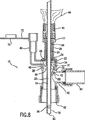
本発明による呼吸装置10は、様々なマニホルド110を備える形態で提供されることができる。例えば、本発明の例示的一実施形態においては、図6に示されるように、呼吸装置10は、T型マニホルド110とともに使用することができる。ポート90を設けることができ、これを人工空気路34(図1)に取り付けることができる。このポート90は、マニホルド110と人工空気路34の間を連通させることができる。このポート92を通して、呼吸器76(図1)からの空気をマニホルド110に及びマニホルドから供与することができる。ポート92は、コネクター(示されていない)を介して一対の換気チューブに取り付けることができる。マニホルド110上において、付加的ポート94を該ポート92の反対側に設けることができる。ポート94は、典型的には、キャップ68で覆われており、このキャップ68は、強制換気から患者18(図1)を解放するために「側流」が望まれる場合には取り外される。付加的ポート46は、呼吸装置10の器具導入区画22に係合する構成とすることができる。
The
吸引カテーテル12を持つ呼吸装置10が、図8に示されており、該カテーテルは、呼吸装置10を通して進ませることができる。呼吸装置10は、いかなる適当な方法ででも吸引カテーテル12のような器具が取り付けられる器具導入区画22を含む。器具導入区画22は、貫通通路24を持つ。吸引カテーテル12の管状部分14は、末端部の開口98を通ってマニホルド110の中に、そして結果的には通路24を通って人工空気路34(図1)に進ませることができる。患者18から管状部分14を引き抜いたとき、呼吸分泌物が管状部分14の表面上に存在することがある。ワイパーシール36を、器具導入区画22内に設けることができる。このワイパーシール36は、管状部分14を通すように、貫通孔を持つ弾性部材とすることができる。ワイパーシール36は、管状部分14が人工空気路34(図1)からワイパーシール36から近位側の位置に引き抜かれる時、該管状部分14と緊密に係合していることが望ましい。管状部分14は、ワイパーシール36に対し近位側に、かつ、図2に示す位置に移動させることができる。管状部分14の表面上に存在する呼吸分泌物は、ワイパーシール36と接触することにより取り除かれる。
A
器具導入区画22内には又、クリーニング区画38を設けることができる。1つの例示的実施形態においては、このクリーニング区画38は、クリーニング区画部材86によって定められる。更に、又は代替的には、このクリーニング区画38は、バルブ32によって1つの端部上に定められる。更にクリーニング区画38は、代替的に器具導入区画22のいずれの部分によっても定めることができる。バルブ32は、図2においては閉位置で、更に図8においては開位置で示されている。図8に示されるバルブ32は、器具導入区画22の中に収容された環状リング31にヒンジ取り付けされた単一フラップである。バルブ32上のヒンジは、付勢力及びピボット位置の両方を与えることができる。このようなバルブ32の使用は、Crump他の米国特許第6,227,200号B1に記載されており、その全体はすべての目的について引用によりここに組み入れられる。
A
図8に示されているように、吸引カテーテル12の管状部分14は、末端開口82を持つ末端部16を備えることができる。内腔20は、管状部分14を通って延び、呼吸分泌物及び他の流体を、真空源78(図1に示されている)によって末端開口82を通して、内腔20にまで移送させることができる。吸引カテーテル12の管状部分14は、吸引カテーテル12の末端部16をバルブ32に対して、又はクリーニング区画38内に位置決めすることによりクリーニングすることができる。このように位置決めされた時、真空が内腔20に付与され、洗浄液又は他のクリーニング溶液がクリーニング区画38内に注入されるようにすることができる。真空の付与は、バルブ32を管状部分14の末端部16に対し押し付けるようにすることができる。しかしながら、他の例示的実施形態においては、バルブ32は、吸引力を付与しないで末端部16に対して閉じかつシールするのに十分な力を備えて付勢されることができる。本発明の1つの例示的実施形態においては、バルブ32は、閉位置において、通路24を少なくとも実質的に遮断することになる。しかしながら、洗浄液又は他のクリーニング溶液の注入及び/又は真空の付与は、吸引カテーテル12の管状部分14のクリーニングと関連のない場合においても行うことができることが理解されるであろう。
As shown in FIG. 8, the
本発明のある種の例示的実施形態においては、バルブ32は、吸引カテーテル12の末端部16と接触するように述べられているが、管状部分14を効率よくクリーニングするためであれば、バルブ32は管状部分14の末端部16と接触する必要はない。例えば、バルブ32は、管状部分14のクリーニングの間に、クリーニング区画部材86に対して押し付けられるようにすることができる。
In certain exemplary embodiments of the present invention, the
管状部分14は、少なくとも1つの側部開口84を設けることができる。この配列は、吸入の間にクリーニング区画38内に乱流を確立して、洗浄溶液によって管状部分14上に存在するあらゆる呼吸分泌物を破砕し、かつ、取り除くようにすることができる。呼吸分泌物は、側部開口84及び/又は末端開口82を通して取り除くことができる。バルブ32には、貫通孔42を設けることができる。孔42の存在は、クリーニング区画38内に一層望ましい乱流状態の流体流を確立するのを助けることができる。本発明の1つの例示的実施形態においては、孔42は、直径が約0.03インチである。
The
洗浄溶液を注入するために、器具導入区画22に取り付けることができる灌注口40が示されている。洗浄溶液を保持するコンテナ(示されていない)は、灌注口40内に挿入された出口を持つことができる。クリーニング区画38に対して連通状態にすることができる灌注口40に、コンテナから洗浄液を送給することができる。灌注口40には灌注キャップ70を設けることができ、該灌注キャップ70は連結紐72によって灌注口40に結合することができる。灌注キャップ70は、使用されない時、灌注口40を閉じるために、灌注口40上に位置させることができる。
An
本発明のある例示的実施形態においては、クリーニング区画部材86は、吸引カテーテル12の管状部分14とクリーニング区画部材86との間に小さい大きさの空間が存在するように構成することができる。本発明のある例示的実施形態においては、この空間は、約0.005インチから約0.015インチの間とすることができる。この空間は、2つの利点をもたらす。第一に、患者18に洗浄を施す必要がある場合に、灌注口40を通してクリーニング区画38内に洗浄液を注入すると、洗浄溶液の流れがマニホルド110を出て、患者18に向くようにすることになる。第二に、管状部分14が引き込まれる場合に、管状部分14とクリーニング区画部材86とが密接していることは、吸引カテーテル12の管状部分14の外側にある吸入分泌物の厚い層を拭き取るように作用する。
In an exemplary embodiment of the invention, the
バルブ32の使用は、吸引カテーテル12の管状部分14が、呼吸回路に圧力損失をもたらすことなくクリーニングされることができるという利点をもたらす。これは、バルブ32が、バルブ32に対し近位側にある呼吸装置10の部分を、呼吸回路の残りの物から実質的に隔離するからである。本発明の1つの例示的実施形態においては、バルブ32には、1つ又はそれより多い突起部88を設けることができる。図8は、マニホルド110が回転ポート62及び64を備えたエルボー型マニホルドとする呼吸装置10を示している。吸引カテーテル12の管状部分14が、器具導入区画22、マニホルド110を通り、ポート62から外に出て、最終的に患者18(図1)の人工空気路34内に入るように進ませられる状態を示している。バルブ32は、器具導入区画22を通して管状部分14を挿入することによって開くことができる。突起部88は、バルブ32が管状部分14の表面と接触するのを最小にするように構成することができる。この接触は、突起部88により可能となる最小の接触のために、バルブ32及び関連する部品が管状部分14からの呼吸分泌物による汚染を減少させるものとなる。更に、ある例示的実施形態においては、この接触は、バルブ32の構造的一体性を確実にすることができ、かつ、バルブ32の不必要な曲げ又は圧力を防ぐことができる。
The use of
本発明の1つの例示的実施形態においては、バルブ32は、閉位置に向けて付勢されるようにすることができる。図8においては、バルブ32は環状リング31に取り付けられるように示されているが、器具導入区画22の壁に直接取り付けることができる。バルブ32は、管状部分14がバルブ32から近位側に位置するとき閉じられるように構成することができ、或いは代替的には、管状部分14をバルブ32から近位側に位置させ、閉位置にバルブ32を引くための真空を内腔20を通して付与し、バルブ32を閉じるように構成することができる。
In one exemplary embodiment of the present invention, the
バルブ32は、単一フラップとする必要はなはない。図示されているバルブ32の形態は、望ましい実施形態というだけであって、バルブ32の他の形態も本発明においては可能であることが理解されるべきである。例えば、バルブ32は、1つ、2つ、又は3つのフラップとすることができ、閉位置に向けて付勢され、カテーテル取付区画22を通して吸引カテーテル12の管状部分14を挿入することにより開かれるものとすることができる。
The
図2を参照すると、器具導入区画22には、近位端部26及び末端部28が設けられている。近位端部26は、当業者によく知られているような種々異なる方法により吸引カテーテル12に取り外し可能に取り付けることができる。例えば、これらの2つの部品は、互いに摩擦嵌合されるか、互いにクランプ係合されるか、突起係合荷より取り外し可能に取り付けられるか、又はねじ係合により結合されることができる。したがって、吸引カテーテル12は、同業者に知られた適当な方法により近位端部26に取り外し可能に取り付けられることができる。
With reference to FIG. 2, the
器具導入区画22の末端部28は、マニホルド110上のポート46に永久的に取り付けることができる。末端部28とポート46の係合が図2に示されている。この例示的実施形態においては、末端部28は、ポート46に取り付けられている。2つの部品は、組立の間に互いに強制嵌合された状態にある。これらは、固定取り付けを提供するために熱処理されることができる。代替的には、2つの部品は、音波溶接、接着剤を介して結合されることができるか、又は他の実施形態においては、1つの一体した部品として形成されることができる。
The
他の例示的実施形態においては、マニホルド110に付加的ポート80を設け、このポート80に呼吸装置10の器具導入区画22を取り付けることができる。更に、本発明のもっと別の例示的実施形態においては、2つの器具導入区画22を採用して、それぞれの器具導入区画22のそれぞれの末端部28が、ポート46及びポート80と取り付け可能な状態となるようにすることができる。
In other exemplary embodiments, the manifold 110 can be provided with an
器具導入区画22の近位端部上に配置されたキャップ100が設けられている呼吸装置10が示されている。キャップ100内の開口102は、吸引カテーテル12が器具導入区画22の近位端部内の開口96を通る前に通すことができるように提供されている。開口102は、様々な器具が呼吸装置10と関連して使用できるような大きさとすることができる。開口102は、プラグ104により閉じることができ、これは連結紐106によってキャップ100と結合されている。図5は、プラグ104が開口102(図4)に挿入された例示的実施形態を示しており、これにより器具導入区画22の近位端部26の開口96が閉じられる。開口96を閉鎖すると、器具が呼吸装置10と結合して使用されない時に周囲から汚染されるような呼吸装置10の汚染を防ぐことができる。更に、患者18が人工呼吸器を使用している間、呼吸回路内の端部の正呼気圧を維持することができるように開口96を閉じることが有益である。バルブ32を使用して端部の正呼気圧を維持することも可能であるが、正の呼気圧を維持する代替的又は補助的方法を提供するために、近位端部26を閉鎖するためにプラグ104を使用することができる。上記したように、キャップ100は、呼吸装置10に設置される必要はない。例えば、図7及び図8は、このようなキャップ100が存在しない例示的実施形態を示している。
Shown is the
図10−12は、本発明の例示的実施形態によるキャップ100及びプラグ104の代替的配置を示している。ここでは、取り付け部材114を設けることができ、例えば、近位端部26のような呼吸装置10の部品に取り付けられることができる。キャップ100は、連結紐106によって取り付け部材114に接合されるように示されており、一方では、プラグ104は別個のプラグ連結紐116によって取り付け部材114に接合されるように示されている。キャップ100は、例えば開口96のような呼吸装置10の部分に配置されることができる。更に望まれれば、プラグ104は、キャップ100の開口102内に配置されることができる。
FIGS. 10-12 illustrate an alternative arrangement of
図2に示されるように、ポート46は、回転ポート62に対して軸整列状態とすることができ、更にこのポートを人工空気路34(図1)に取り付けることができる。この整列は、吸引カテーテル12(図1)を患者18(図1)から引き抜く時に、バルブ32に近位側にある器具導入区画22の方向に引き抜くために、吸引カテーテル12が曲げられたり又は他の物体を越える必要がないという事実により汚染を減少させることができる。効率的には、この整列は「直接的な対策」であり、呼吸分泌物が吸引カテーテル12の管状部分14で砕かれ、かつ、呼吸装置10の曲げ又は他の障害物上に堆積されるといった機会を減少させるものである。回転部材60をマニホルド110上に設け、これがポート46及び80を回転させ、ポート80が回転ポート62と軸整列状態になり、したがってポート46がポート62との軸整列状態から外れるように動かされるようにすることができる。ポート80を通して挿入された吸引カテーテル12は、呼吸装置10を通して移送させるために、曲げを越えて又は障害物に対して移動させる必要はない。ポート46及び80の1つだけが、どんな時でも回転ポート62と軸整列状態となる。マニホルド110のこの形式は、Lorenzen他の米国特許第5,735,271号に記載されており、その全体はすべての目的について引用によりここに組み入れられる。しかしながら、図2に示されるマニホルド110の形態は本発明の例示的実施形態だけであり、本発明は、マニホルド110の末端ポートと軸整列状態とすることができるような回転ポートを持つマニホルド110に制限されるものではない。本発明による呼吸装置10は、当業者に知られているあらゆる形態のマニホルド110を設置することができる。
As shown in FIG. 2, the
マニホルド110は、呼吸器76(図1)に対して連通状態にあるように位置された別の回転ポート64を持つ。これら2つのポート62及び64は、呼吸回路の様々な部分が操作され移動される時に、これらに連結された管及び/又は構造が移動しやすいような回転特性を持つように構成することができる。このことは、呼吸回路の移動によって患者18に与えられるストレスを減少させるものである。回転ポート62及び64は、例えば、Palmer他の米国特許第5,694,922号に記載されているように形成することができ、この特許はその全体がすべての目的について引用によりここに組み入れられる。
The manifold 110 has another
本発明の別の例示的実施形態が図3に示されている。ここで、呼吸装置10は、図2に示された例示的実施形態に関連して述べられた呼吸装置10と実質的に類似するものとすることができる。しかしながら、マニホルド110は、この場合においては、1対の回転ポート62及び64を持つエルボー型マニホルドである。マニホルド110は、回転部材を持つようには示されておらず、残りのマニホルド110に関しては、ポート46は固定されている。
Another exemplary embodiment of the present invention is shown in FIG. Here, the
本発明の別の例示的実施形態が図4に示されている。ここでは、マニホルド110はエルボー型マニホルドとすることができ、その上に回転特性は含まないポート90及び92が配置される。これらの2つのポートは呼吸回路の一部分を形成するもので、ポート90を通して患者18(図1)に向かって、及び患者18からの空気を通し、更にポート92を通して呼吸器76(図1)に向かって、及び呼吸器からの空気を通す。
Another exemplary embodiment of the present invention is shown in FIG. Here, the manifold 110 can be an elbow type manifold, on which
本発明の別の例示的実施形態により使用される別のマニホルド110が図5に示されている。ここでは、マニホルド110は、複数のポートを持つ新生児用マニホルドとする。ポート46ではない他のポートが存在し、ポート46に加えて2つのポートが符号を付して示されている。ポート92は、呼吸器76(図1)へのアクセス及び呼吸器からのアクセスを提供することができ、又ポート90は、患者18(図1)の人工空気路34(図1)への及び人工空気路からのアクセスを提供することができる。ポート46は、器具導入区画22の末端部28に取り付けられることができる。
Another manifold 110 used in accordance with another exemplary embodiment of the present invention is shown in FIG. Here, the manifold 110 is a newborn manifold having a plurality of ports. There are other ports that are not
本発明の付加的例示的実施形態が図7に示されている。ここでは、呼吸装置10は、新生児用Y型マニホルドとするマニホルド110を含むことができる。末端部28は、マニホルド110上でポート46と結合されることができる。マニホルド110のポート90及び92は、呼吸器76(図1)と人工空気路34(図1)の間を連通させるものである。テーパ状アダプター112をポート90内に保持して、呼吸装置10を管又は呼吸回路の他の部品と結合させることができる。テーパ状アダプター112は、ポート90に永久的に取り付けることもできるし、取り付けないこともできる。代替的には、マニホルド110自体は、テーパ状とすることができ、よって本発明の他の例示的実施形態においては、テーパ状アダプター112の必要性を排除する。
An additional exemplary embodiment of the present invention is shown in FIG. Here, the
本発明によれば、呼吸装置10は、種々異なる人工空気路構造30に取り付けることができるような大きさとすることができる。更に呼吸装置10は、異なる大きさの近位端部26、バルブ32、及びワイパーシール36などを備えた大きさとすることができ、異なる大きさの器具が呼吸装置10に使用されることができる。このように本発明は、呼吸装置10の様々な大きさ及び形態を含む。ここで述べられた例は、本発明の例示的実施形態のみのものであって、本発明を制限するものではない。
According to the present invention, the
本発明は、吸引カテーテル12に連結して使用されるように述べられてきたが、器具は、本発明の他の例示的実施形態による吸引カテーテル12ではない他のものとすることができることが理解されるであろう。例えば、図9は、気管支鏡108が挿入された呼吸装置10が示されている。気管支鏡108は、通路24を通って、マニホルド110まで、更に患者18(図1)の人工空気路34(図1)まで挿入されることができる。又、気管支鏡108は、吸引カテーテル12(図1)に関して上記されたのとほとんど同じ方法で清浄されることができる。例えば、気管支鏡108のチップは、バルブ32の近位側に配置され、洗浄溶液をクリーニング区画38に注入することができ、かつ、気管支鏡を通して吸引され、呼吸分泌物が気管支鏡108の表面から取り除かれる。更に、内視鏡のような他の器具が、呼吸装置10と関連して使用されることができる。呼吸装置10は、異なる器具を配置させても、清浄溶液の挿入及び/又は吸引の付与により清浄されることができる。呼吸装置10は、マニホルド110を取り外さず、更に患者への呼吸空気に対する前述したような干渉をすることなく、異なる形式の器具を人工空気路34(図1)に挿入させることができる。更に、バルブ32は、閉位置にある時、端部の正呼気圧を維持するように機能することができる。本発明は、吸引カテーテル12と関連して使用される呼吸装置10に制限されるものではなく、人工空気路34(図1)に挿入されるあらゆる器具と使用されることができることが理解される。
Although the present invention has been described as being used in conjunction with an
吸引カテーテル12のような器具が、呼吸装置10に取り外し可能に取り付けられることは、呼吸回路と干渉せずに呼吸装置10を他に使用することを可能にする。したがって、異なる形式の器具を、呼吸装置10に互換性を持って使用することができる。呼吸装置10は、呼吸回路の空気路圧を計測することができる。呼吸装置10の別の使用方法は、患者18に酸素及び通気治療を行うことができるような人工空気路34へのアクセスを提供することである。又、呼吸装置10は、近位端部26に取り付けられるフィルター装置(示されていない)を持つことができ、患者18は、呼吸器76の使用を通して人工呼吸から開放されることができる。したがって、呼吸装置10は、様々な器具とともに使用されるように設計され、呼吸回路を中断せず、かつ、これらに関連する不利な事柄に煩わされずに患者18に施される様々な医療処置に関連して使用されることができる。
Removably attached to the
本発明は、添付された特許請求の範囲及びその均等手段の範囲内となる、ここに記載された呼吸装置の実施形態に対して行うことができる様々な修正を含むことを理解すべきである。 It is to be understood that the invention includes various modifications that can be made to the embodiments of the respiratory device described herein that are within the scope of the appended claims and their equivalents. .
10 呼吸装置
12 吸引カテーテル
18 患者
20 内腔
22 器具導入区画
32 バルブ
34 人工空気路
40 灌注口
100 キャップ
110 マニホルド
DESCRIPTION OF
Claims (12)
患者の人工空気路に対して連通状態で結合するように構成されたマニホルドであって、前記マニホルドは、末端ポートと、前記末端ポートに対して相対的な回転が可能な少なくとも2つの近位ポートとを持ち、前記少なくとも2つの近位ポートのなかの1つのみが、前記末端ポートと軸整列状態になる、該マニホルドと、
それぞれ、前記患者の前記人工空気路に器具を導入するために前記マニホルドの前記近位ポートに取り付けられた末端部を備えた、2以上の器具導入区画と、
を備え、
前記2以上の器具導入区画のそれぞれは、
前記器具導入区画への前記器具の挿入を可能にする開口を持つ、前記器具に取り外し可能に取り付けられるように構成された近位端部と、
前記器具が移動可能で、前記近位端部の前記開口から前記末端部内の開口までの通路と、
閉位置と開位置とを有し、前記閉位置のとき、前記通路を少なくとも実質的に遮断し、前記開位置のとき、前記器具導入区画を通して前記器具を進ませることができる、前記器具導入区画内に配置されたバルブと、
その遠位端が前記バルブによって画定されるように、前記バルブから近位側において前記器具導入区画内に配置されたクリーニング区画と、
流体を前記クリーニング区画に移送させるように構成された、前記クリーニング区画に対して連通状態にある灌注口と、
を含み、
前記器具導入区画の前記末端部が取り付けられた前記マニホルドの前記近位ポートの1つが前記マニホルドの前記末端ポートと軸整列状態であるとき、前記バルブが前記開位置となって、前記灌注口を通して導入された洗浄液を通過させて患者に向けられるように構成される
ことを特徴とする装置。A breathing device,
A manifold configured to couple in communication with an artificial airway of a patient, the manifold including a distal port and at least two proximal ports capable of relative rotation with respect to the distal port preparative has, Nakano only one of the at least two proximal ports, becomes the distal port and the shaft alignment, and said manifold,
Two or more instrument introduction sections each having a distal end attached to the proximal port of the manifold for introducing an instrument into the artificial airway of the patient;
With
Each of the two or more instrument introduction sections is
A proximal end configured to be removably attached to the instrument having an opening that allows insertion of the instrument into the instrument introduction section;
A path from the opening at the proximal end to the opening in the distal end;
And a closed position and an open position, wherein when in the closed position, said passage at least substantially block, when the open position, the Ru can propel the instrument through the instrument introduction section, the instrument introduction A valve located in the compartment;
A cleaning compartment disposed in the instrument introduction compartment proximally from the valve such that its distal end is defined by the valve;
An irrigation port in communication with the cleaning compartment configured to transfer fluid to the cleaning compartment;
Including
When said one of said proximal port of said manifold said distal end is attached to the instrument introduction section is a said end port and the axial alignment of the manifold, and wherein the valve is a said open position, said irrigation port A device characterized in that it is configured to be passed to a patient through a cleaning solution introduced through the device.
前記器具導入区画の前記近位端部内の前記開口への前記器具の挿入を可能にする開口を持ち、前記器具導入区画の前記近位端部と係合するように構成されたキャップと、
プラグ連結紐を持ち、前記キャップの前記開口を閉じるように前記キャップ内の前記開口に挿入可能なプラグと、
を更に含むことを特徴とする請求項1に記載の呼吸装置。For each of the instrument introduction sections,
A cap having an opening that allows insertion of the instrument into the opening in the proximal end of the instrument introduction section and configured to engage the proximal end of the instrument introduction section;
A plug having a plug connection string, and a plug that can be inserted into the opening in the cap so as to close the opening of the cap;
The respiratory apparatus of claim 1, further comprising:
患者の人工空気路に対して連通状態とするように構成されたマニホルドであって、前記マニホルドは、末端ポートと、前記末端ポートに対して相対的な回転が可能な少なくとも2つの近位ポートとを持ち、前記少なくとも2つの近位ポートのなかの1つのみが、前記末端ポートと軸整列状態になる、該マニホルドと、
それぞれ、前記患者の前記人工空気路に器具を導入するための、前記マニホルドの前記近位ポートに取り付けられた末端部を備えた、2以上の器具導入区画と、
を備え、
前記2以上の器具導入区画のそれぞれは、
前記器具導入区画への前記器具の挿入を可能にする開口を持ち、前記器具に取り外し可能に取り付けるように構成された近位端部と、
前記近位端部内の前記開口から前記末端部内の開口までの通路と、
閉位置と開位置とを有し、前記閉位置のとき、前記通路を少なくとも実質的に遮断し、前記開位置の時、前記器具導入区画を通して前記器具を進ませることができる、前記器具導入区画内に配置されたバルブと、
その遠位端が前記バルブによって画定されるように、前記バルブから近位側において前記器具導入区画内に設置されたクリーニング区画と、
流体を前記クリーニング区画に移送させるように構成された、前記クリーニング区画に対して連通状態にある灌注口と、
を含み、
前記呼吸装置はさらに、前記器具導入区画のそれぞれについて、
前記器具導入区画の前記近位端部と係合可能で、前記器具導入区画の前記近位端部内の前記開口を通して前記通路を周囲から遮断することが可能なプラグと、
前記器具導入区画の前記近位端部内の前記開口への前記器具の挿入を可能にする開口を持ち、前記器具導入区画の前記近位端部と係合するように構成されたキャップと、
前記プラグを前記キャップに連結する連結紐と、
を更に備え、
前記器具導入区画の前記末端部が取り付けられた前記マニホルドの前記近位ポートの1つが前記マニホルドの前記末端ポートと軸整列状態であるとき、前記バルブが前記開位置となって、前記灌注口を通して導入された洗浄液を通過させて患者に向けられるように構成され、
かつ前記プラグは、前記キャップ内の前記開口を閉じるように前記キャップ内の前記開口に挿入可能で、その時同時に前記近位端部内の前記開口と前記キャップ内の前記開口を通して周囲から前記器具導入区画の前記通路を遮断することを特徴とする呼吸装置。A breathing device,
A manifold configured to the communicating state with respect to an artificial airway of a patient, the manifold has a distal port, and at least two proximal ports that can be relative rotation with respect to said distal port the have, Nakano only one of the at least two proximal ports, becomes the distal port and the shaft alignment, and said manifold,
Two or more instrument introduction sections each having a distal end attached to the proximal port of the manifold for introducing an instrument into the artificial airway of the patient;
With
Each of the two or more instrument introduction sections is
A proximal end having an opening to allow insertion of the instrument into the instrument introduction section and configured to be removably attached to the instrument;
A passage from the opening in the proximal end to the opening in the distal end;
And a closed position and an open position, when the closed position, said passage at least substantially block, when the open position, Ru can propel the instrument through the instrument introduction section, the instrument introduction a valve disposed in the compartment,
A cleaning compartment located in the instrument introduction compartment proximally from the valve such that its distal end is defined by the valve;
An irrigation port in communication with the cleaning compartment configured to transfer fluid to the cleaning compartment;
Including
The respiratory apparatus further includes:
A plug engageable with the proximal end of the instrument introduction section and capable of blocking the passageway from the surroundings through the opening in the proximal end of the instrument introduction section;
A cap having an opening that allows insertion of the instrument into the opening in the proximal end of the instrument introduction section and configured to engage the proximal end of the instrument introduction section;
A connecting string connecting the plug to the cap;
Further comprising
When said one of said proximal port of said manifold said distal end is attached to the instrument introduction section is a said end port and the axial alignment of the manifold, and wherein the valve is a said open position, said irrigation port Configured to be passed to the patient through the cleaning solution introduced through,
And the plug is insertable into the opening in the cap so as to close the opening in the cap, and at the same time through the opening in the proximal end and the opening in the cap from the periphery to the instrument introduction section. A respiratory apparatus characterized by blocking the passage.
Applications Claiming Priority (3)
| Application Number | Priority Date | Filing Date | Title |
|---|---|---|---|
| US10/430,813 US7263997B2 (en) | 2003-05-06 | 2003-05-06 | Respiratory apparatus having an instrument introduction section and manifold |
| US10/430,813 | 2003-05-06 | ||
| PCT/US2004/001409 WO2004103448A1 (en) | 2003-05-06 | 2004-01-20 | Respiratory apparatus having an instrument introduction section and manifold |
Publications (3)
| Publication Number | Publication Date |
|---|---|
| JP2006528530A JP2006528530A (en) | 2006-12-21 |
| JP2006528530A5 JP2006528530A5 (en) | 2007-02-08 |
| JP5179057B2 true JP5179057B2 (en) | 2013-04-10 |
Family
ID=33416319
Family Applications (1)
| Application Number | Title | Priority Date | Filing Date |
|---|---|---|---|
| JP2006532261A Expired - Lifetime JP5179057B2 (en) | 2003-05-06 | 2004-01-20 | Respirator with instrument introduction compartment and manifold |
Country Status (10)
| Country | Link |
|---|---|
| US (1) | US7263997B2 (en) |
| EP (1) | EP1620151A1 (en) |
| JP (1) | JP5179057B2 (en) |
| KR (1) | KR101055132B1 (en) |
| AU (1) | AU2004241928B2 (en) |
| BR (1) | BRPI0409722A (en) |
| CA (1) | CA2523488C (en) |
| MX (1) | MXPA05011395A (en) |
| NO (1) | NO20054948L (en) |
| WO (1) | WO2004103448A1 (en) |
Families Citing this family (41)
| Publication number | Priority date | Publication date | Assignee | Title |
|---|---|---|---|---|
| US10363092B2 (en) | 2006-03-24 | 2019-07-30 | Neuwave Medical, Inc. | Transmission line with heat transfer ability |
| US7527058B2 (en) * | 2006-06-14 | 2009-05-05 | Medical Device Group, Inc. | Respiratory suction catheter assembly |
| US11389235B2 (en) | 2006-07-14 | 2022-07-19 | Neuwave Medical, Inc. | Energy delivery systems and uses thereof |
| US10376314B2 (en) | 2006-07-14 | 2019-08-13 | Neuwave Medical, Inc. | Energy delivery systems and uses thereof |
| US8012141B2 (en) * | 2007-03-29 | 2011-09-06 | Wright Clifford A | Suction wand |
| US20100147296A1 (en) * | 2008-12-12 | 2010-06-17 | John Brewer | Port Sealing Cartridge for Medical Ventilating and Aspirating Devices |
| US8215306B2 (en) * | 2008-12-12 | 2012-07-10 | Kimberly-Clark Worldwide, Inc. | Respiratory access port assembly with push button lock and method of use |
| US20100147312A1 (en) * | 2008-12-12 | 2010-06-17 | John Brewer | Respiratory Access Port Assembly With Pin Lock and Method of Use |
| US8205913B2 (en) * | 2008-12-31 | 2012-06-26 | Kimberly-Clark Worldwide, Inc. | Respiratory triple swivel manifold |
| US8444627B2 (en) * | 2008-12-31 | 2013-05-21 | Kimberly-Clark Worldwide, Inc. | Respiratory manifold with bridge |
| US8628056B2 (en) * | 2009-02-02 | 2014-01-14 | Aptargroup, Inc. | Dual sealing system for use with a probe |
| GB0901945D0 (en) * | 2009-02-09 | 2009-03-11 | Young Peter J | Visualized suction catheter |
| US8256422B2 (en) * | 2009-05-15 | 2012-09-04 | Kimberly-Clark Worldwide, Inc | Respiratory access port assembly with passive lock and method of use |
| DK2459096T3 (en) | 2009-07-28 | 2015-01-19 | Neuwave Medical Inc | ablation device |
| GB0914557D0 (en) | 2009-08-20 | 2009-09-30 | Smiths Medical Int Ltd | Ventilation and suction systems and assemblies |
| EP3804651A1 (en) | 2010-05-03 | 2021-04-14 | Neuwave Medical, Inc. | Energy delivery systems |
| KR101038781B1 (en) | 2011-02-07 | 2011-06-03 | (주)메다스 | An easily disconnective closed suction catheter |
| CN107224325B (en) | 2011-12-21 | 2020-09-01 | 纽华沃医药公司 | Energy delivery system and use thereof |
| US9078987B2 (en) | 2011-12-23 | 2015-07-14 | Avent, Inc. | Clutch brake assembly for a respiratory access port |
| US10173023B1 (en) | 2014-02-07 | 2019-01-08 | Victor G. Ghobrial | Oropharyngeal device |
| US9956372B2 (en) * | 2015-03-09 | 2018-05-01 | Phillip Polin | Tracheal humidification device |
| WO2017075067A1 (en) | 2015-10-26 | 2017-05-04 | Neuwave Medical, Inc. | Energy delivery systems and uses thereof |
| JP2018534108A (en) | 2015-10-26 | 2018-11-22 | ニューウェーブ メディカル, インコーポレイテッドNeuwave Medical, Inc. | Apparatus for securing medical devices and related methods |
| EP3808302B1 (en) | 2016-04-15 | 2023-07-26 | Neuwave Medical, Inc. | System for energy delivery |
| GB201617855D0 (en) * | 2016-10-21 | 2016-12-07 | Teleflex Life Sciences Unlimited Co | Artificial airway device |
| CA3050868A1 (en) * | 2016-12-30 | 2018-07-05 | Endoclear Llc | Artificial airway management devices, systems and methods |
| US10869979B2 (en) | 2017-08-09 | 2020-12-22 | Eric A. Cantor | Supraglottic airway device |
| GB201717237D0 (en) | 2017-10-20 | 2017-12-06 | Smiths Medical International Ltd | Suction catheter assemblies |
| US20190246876A1 (en) | 2018-02-15 | 2019-08-15 | Neuwave Medical, Inc. | Compositions and methods for directing endoscopic devices |
| US11672596B2 (en) | 2018-02-26 | 2023-06-13 | Neuwave Medical, Inc. | Energy delivery devices with flexible and adjustable tips |
| EP3886959B1 (en) | 2018-11-27 | 2024-03-13 | Neuwave Medical, Inc. | Endoscopic system for energy delivery |
| WO2020112852A1 (en) * | 2018-11-29 | 2020-06-04 | Board Of Regents, The University Of Texas System | Devices, systems and methods for cleaning of elongated instrument surface |
| GB201902868D0 (en) | 2019-03-02 | 2019-04-17 | Smiths Medical International Ltd | Suction catheter assemblies and assemblies including a suction catheter assembly |
| US11832879B2 (en) | 2019-03-08 | 2023-12-05 | Neuwave Medical, Inc. | Systems and methods for energy delivery |
| GB201915251D0 (en) | 2019-10-22 | 2019-12-04 | Smiths Medical International Ltd | Connectors and assemblies |
| US11013399B1 (en) * | 2020-01-27 | 2021-05-25 | Board Of Regents, The University Of Texas System | Wiper assembly for imaging element cleaning apparatus |
| IES87399Y1 (en) * | 2020-03-26 | 2023-06-07 | Palliare Ltd | An adapter for a face mask, and an instrument shielding apparatus for shielding an instrument being entered into a subject through a face mask or a trocar |
| GB202006539D0 (en) | 2020-05-04 | 2020-06-17 | Smiths Medical International Ltd | Closed-system suction catheter assemblies |
| GB202011662D0 (en) | 2020-07-28 | 2020-09-09 | Smiths Medical International Ltd | Closed-system suction catheter |
| WO2022238668A1 (en) | 2021-05-10 | 2022-11-17 | Smiths Medical International Limited | Suction catheter assemblies |
| US20230088132A1 (en) | 2021-09-22 | 2023-03-23 | NewWave Medical, Inc. | Systems and methods for real-time image-based device localization |
Family Cites Families (68)
| Publication number | Priority date | Publication date | Assignee | Title |
|---|---|---|---|---|
| US3991762A (en) | 1974-09-30 | 1976-11-16 | Radford F Richard | Aspirating device for patient ventilation apparatus |
| US4152017A (en) | 1977-08-08 | 1979-05-01 | Metatech Corporation | Swivel connector for endotracheal tube or the like |
| US4416273A (en) | 1981-06-15 | 1983-11-22 | Grimes Jerry L | Connector valve assembly for endotracheal tubes |
| DE3222539C2 (en) | 1982-06-16 | 1984-07-26 | Drägerwerk AG, 2400 Lübeck | Suction adapter and suction device set using this adapter |
| US4573965A (en) | 1984-02-13 | 1986-03-04 | Superior Plastic Products Corp. | Device for draining wounds |
| US4872579A (en) | 1984-07-23 | 1989-10-10 | Ballard Medical Products | Aspirating/ventilating apparatus and method |
| US4696296A (en) | 1984-07-23 | 1987-09-29 | Ballard Medical Products | Aspirating/ventilating apparatus |
| US4569344A (en) | 1984-07-23 | 1986-02-11 | Ballard Medical Products | Aspirating/ventilating apparatus and method |
| US4836199A (en) | 1984-07-23 | 1989-06-06 | Ballard Medical Products | Aspirating/ventilating apparatus and method |
| US4607635A (en) | 1984-09-27 | 1986-08-26 | Heyden Eugene L | Apparatus for intubation |
| JPS62211074A (en) | 1986-03-07 | 1987-09-17 | ボ−ド・オブ・リ−ジエンツ、ザ・ユニバ−シテイ−・オブ・テキサス・システム | Suction catheter with leading end balloon |
| GB2199630A (en) | 1986-12-01 | 1988-07-13 | Portex Inc | Plug |
| US4846167A (en) | 1987-03-30 | 1989-07-11 | Tibbals James R | Anti-disconnect device |
| US5582165A (en) | 1988-02-28 | 1996-12-10 | Bryan; James F. | Pre-assembled sealed, sheathed catheters and related valve elements with quick disconnect means for endotracheal suctioning |
| USD312880S (en) * | 1988-03-04 | 1990-12-11 | Bodai Balazs I | Neonatal suction valve |
| US5220916A (en) * | 1990-06-14 | 1993-06-22 | Russo Ronald D | Tracheal suction catheter |
| US5083561B1 (en) | 1990-06-14 | 1993-05-18 | D. Russo Ronald | Tracheal suction catheter |
| US5139018A (en) | 1990-07-24 | 1992-08-18 | Superior Healthcare Group, Inc. | Patient ventilating apparatus with aspirating catheter |
| US5062420A (en) | 1990-09-18 | 1991-11-05 | Walter Levine | Sealed swivel for respiratory apparatus |
| US5218957A (en) | 1990-10-19 | 1993-06-15 | Ballard Medical Products | Multi-layered transtracheal catheter |
| US5199427A (en) | 1990-10-19 | 1993-04-06 | Ballard Medical Products | Multi-layered transtracheal caatheter |
| US5230332A (en) | 1990-10-22 | 1993-07-27 | Ballard Medical Products | Methods and apparatus for a micro-tracheal catheter hub assembly |
| US5255676A (en) | 1991-11-08 | 1993-10-26 | Russo Ronald D | Safety sealed tracheal suction system |
| US5309902A (en) | 1992-10-19 | 1994-05-10 | Sherwood Medical Company | Respiratory support system and suction catheter device therefor |
| US5333606A (en) * | 1992-04-24 | 1994-08-02 | Sherwood Medical Company | Method for using a respirator accessory access port and adaptor therefore |
| US5355876A (en) | 1992-05-06 | 1994-10-18 | Superior Healthcare Group, Inc. | Patient ventilating apparatus with modular components |
| US5645048A (en) | 1992-05-06 | 1997-07-08 | The Kendall Company | Patient ventilating apparatus with modular components |
| GB2270845B (en) | 1992-09-24 | 1996-07-10 | Smiths Ind Med Syst Inc | Suction catheter assemblies |
| US5628306A (en) * | 1992-10-19 | 1997-05-13 | Kee; Kok-Hiong | Respiratory manifold with accessory access port |
| US5445141A (en) | 1992-10-19 | 1995-08-29 | Sherwood Medical Company | Respiratory support system |
| US5349950A (en) | 1992-10-28 | 1994-09-27 | Smiths Industries Medical Systems, Inc. | Suction catheter assemblies |
| US5254098A (en) | 1993-02-16 | 1993-10-19 | Smiths Industries Medical Systems, Inc. | Suction catheter assemblies |
| US5513628A (en) * | 1993-07-14 | 1996-05-07 | Sorenson Critical Care, Inc. | Apparatus and method for ventilating and aspirating |
| US5433195A (en) | 1993-09-30 | 1995-07-18 | Sherwood Medical Company | Respiratory support system |
| US5676136A (en) | 1993-12-07 | 1997-10-14 | Russo; Ronald D. | Protective suction control catheter with valve |
| US5694922A (en) | 1994-05-18 | 1997-12-09 | Ballard Medical Products | Swivel tube connections with hermetic seals |
| US5735271A (en) * | 1994-05-18 | 1998-04-07 | Ballard Medical Products | Multiple access adaptors for monitoring, sampling, medicating, aspirating, and ventilating the respiratory tract of a patient |
| US6012451A (en) | 1994-08-19 | 2000-01-11 | Ballard Medical Products | Medical aspirating/ventilating closed system improvements and methods |
| US6494203B1 (en) | 1994-08-19 | 2002-12-17 | Ballard Medical Products | Medical aspirating/ventilating closed system improvements and methods |
| DE69430145T2 (en) | 1994-09-19 | 2002-10-31 | Sorenson Medical Inc | VENTILATE AND ASPIRATE DEVICE |
| US5582161A (en) | 1994-12-08 | 1996-12-10 | Sherwood Medical Company | Sheathed catheter adapter and method of use |
| US5711294A (en) | 1994-12-21 | 1998-01-27 | Sherwood Medical Company | Ventilator manifold having cleaning ports and method of use thereof |
| US5664594A (en) | 1994-12-29 | 1997-09-09 | Sherwood Medical Company | Cleaning device for ventilator manifold and method of use thereof |
| DE69533070T2 (en) | 1995-02-28 | 2004-09-23 | Ballard Medical Products, Draper | VENTILATION DEVICES WITH CONTROLLED ACCESS |
| US5598840A (en) | 1995-03-17 | 1997-02-04 | Sorenson Critical Care, Inc. | Apparatus and method for ventilation and aspiration |
| US5775325A (en) | 1995-05-11 | 1998-07-07 | Russo; Ronald D. | Two part closed tracheal suction system |
| US6318368B1 (en) | 1996-03-11 | 2001-11-20 | Orlando Morejon | Endotracheal tube cleaning apparatus |
| US6082361A (en) | 1997-09-12 | 2000-07-04 | Morejon; Orlando | Endotracheal tube cleaning apparatus |
| US5882348A (en) * | 1997-02-03 | 1999-03-16 | Sorenson Critical Care, Inc. | Valved manifold |
| US5919174A (en) * | 1997-02-03 | 1999-07-06 | Sorenson Critical Care, Inc. | Suction valve assembly |
| US6026810A (en) | 1997-07-30 | 2000-02-22 | Baird; David A. | One hand disconnectable device for artificial breathing apparatus to endotracheal tube connections |
| US6165168A (en) | 1997-09-02 | 2000-12-26 | Russo; Ronald D. | Closed system adapter for catheters |
| AU6389699A (en) | 1998-09-17 | 2000-04-03 | Ballard Medical Products | Respiratory suction catheter apparatus |
| US6227200B1 (en) * | 1998-09-21 | 2001-05-08 | Ballard Medical Products | Respiratory suction catheter apparatus |
| US7021313B1 (en) * | 1998-09-21 | 2006-04-04 | Ballard Medical Products | Respiratory suction catheter apparatus with improved valve and collar |
| BR9804529A (en) | 1998-10-23 | 2000-04-25 | Newmed Importadora Ltda | Device for performing secretion aspiration in intubated or trachenostomized patients and kit containing a device for performing secretion aspiration in intubated or tracheostomized patients. |
| US6615835B1 (en) * | 1999-09-20 | 2003-09-09 | Ballard Medical Products | Flexible multiple port adaptor |
| US6584970B1 (en) * | 1999-10-05 | 2003-07-01 | Ballard Medical Products | Retaining plug for endotracheal catheter and manifold assembly and method of use |
| ES2291232T3 (en) | 1999-12-13 | 2008-03-01 | Kimberly-Clark Worldwide, Inc. | ENDOTRAQUEAL CATHETER AND COLLECTOR ASSEMBLY WITH IMPROVED VALVE. |
| US7152603B1 (en) | 1999-12-13 | 2006-12-26 | Kimberly-Clark Worldwide, Inc. | Endotracheal catheter and manifold assembly with improved valve |
| US6543451B1 (en) | 1999-12-23 | 2003-04-08 | Kimberly-Clark Worldwide, Inc. | Endotracheal catheter and manifold assembly with improved seal and valve |
| DK1267957T3 (en) * | 2000-04-06 | 2008-02-11 | Unomedical As | Manifold |
| US6612304B1 (en) * | 2000-10-05 | 2003-09-02 | Kimberly-Clark Worldwide, Inc. | Respiratory care multiple access port assembly and adapter |
| US6609520B1 (en) | 2000-10-31 | 2003-08-26 | Kimberly-Clark Worldwide, Inc. | Closed suction catheter adaptor and assembly containing the same |
| IT1319876B1 (en) | 2000-11-24 | 2003-11-03 | D E A S S R L | IMPROVEMENTS IN CLOSED CIRCUIT BRONCOSPIRATION SYSTEMS. |
| US6602219B2 (en) * | 2000-12-19 | 2003-08-05 | Kimberly-Clark Worldwide, Inc. | Turbulent air cleaning method and apparatus for catheter assemblies |
| US6588425B2 (en) * | 2000-12-21 | 2003-07-08 | Kimberly-Clark Worldwide, Inc. | Respiratory suction catheter apparatus with antimicrobial chamber |
| US6629530B2 (en) | 2000-12-22 | 2003-10-07 | Kimberly-Clark Worldwide, Inc. | Single-element sealing valve for a respiratory support system |
-
2003
- 2003-05-06 US US10/430,813 patent/US7263997B2/en active Active
-
2004
- 2004-01-20 CA CA2523488A patent/CA2523488C/en not_active Expired - Lifetime
- 2004-01-20 MX MXPA05011395A patent/MXPA05011395A/en active IP Right Grant
- 2004-01-20 JP JP2006532261A patent/JP5179057B2/en not_active Expired - Lifetime
- 2004-01-20 WO PCT/US2004/001409 patent/WO2004103448A1/en active Application Filing
- 2004-01-20 KR KR1020057020149A patent/KR101055132B1/en active IP Right Grant
- 2004-01-20 AU AU2004241928A patent/AU2004241928B2/en not_active Expired
- 2004-01-20 EP EP04703668A patent/EP1620151A1/en not_active Ceased
- 2004-01-20 BR BRPI0409722-0A patent/BRPI0409722A/en not_active IP Right Cessation
-
2005
- 2005-10-25 NO NO20054948A patent/NO20054948L/en unknown
Also Published As
| Publication number | Publication date |
|---|---|
| AU2004241928A1 (en) | 2004-12-02 |
| MXPA05011395A (en) | 2005-12-12 |
| US7263997B2 (en) | 2007-09-04 |
| KR20060007031A (en) | 2006-01-23 |
| NO20054948L (en) | 2005-10-25 |
| KR101055132B1 (en) | 2011-08-08 |
| CA2523488A1 (en) | 2004-12-02 |
| EP1620151A1 (en) | 2006-02-01 |
| BRPI0409722A (en) | 2006-05-02 |
| JP2006528530A (en) | 2006-12-21 |
| AU2004241928B2 (en) | 2009-10-29 |
| CA2523488C (en) | 2011-03-29 |
| US20040221842A1 (en) | 2004-11-11 |
| WO2004103448A1 (en) | 2004-12-02 |
Similar Documents
| Publication | Publication Date | Title |
|---|---|---|
| JP5179057B2 (en) | Respirator with instrument introduction compartment and manifold | |
| JP5068536B2 (en) | Respiratory device having an introduction section configured to be removably attached to a respiratory device | |
| JP4604039B2 (en) | Respiratory suction catheter device configured to be removably attached to an artificial airway structure | |
| JP4275536B2 (en) | Heat and moisture exchanger adapter for a closed suction catheter assembly and system with improved catheter cleaning | |
| US7021313B1 (en) | Respiratory suction catheter apparatus with improved valve and collar | |
| WO2007058676A1 (en) | Respiratory apparatus with improved seal | |
| EP1113835B1 (en) | Respiratory suction catheter apparatus | |
| US20040007236A1 (en) | Endotracheal surfactant distribution system | |
| JP3630684B2 (en) | Bronchial suction device with valve adjustment for endotracheal tube |
Legal Events
| Date | Code | Title | Description |
|---|---|---|---|
| A521 | Request for written amendment filed |
Free format text: JAPANESE INTERMEDIATE CODE: A523 Effective date: 20061214 |
|
| A621 | Written request for application examination |
Free format text: JAPANESE INTERMEDIATE CODE: A621 Effective date: 20061214 |
|
| RD02 | Notification of acceptance of power of attorney |
Free format text: JAPANESE INTERMEDIATE CODE: A7422 Effective date: 20090728 |
|
| RD04 | Notification of resignation of power of attorney |
Free format text: JAPANESE INTERMEDIATE CODE: A7424 Effective date: 20090812 |
|
| A131 | Notification of reasons for refusal |
Free format text: JAPANESE INTERMEDIATE CODE: A131 Effective date: 20091006 |
|
| A521 | Request for written amendment filed |
Free format text: JAPANESE INTERMEDIATE CODE: A523 Effective date: 20091225 |
|
| A131 | Notification of reasons for refusal |
Free format text: JAPANESE INTERMEDIATE CODE: A131 Effective date: 20100302 |
|
| A521 | Request for written amendment filed |
Free format text: JAPANESE INTERMEDIATE CODE: A523 Effective date: 20100531 |
|
| A131 | Notification of reasons for refusal |
Free format text: JAPANESE INTERMEDIATE CODE: A131 Effective date: 20101102 |
|
| RD13 | Notification of appointment of power of sub attorney |
Free format text: JAPANESE INTERMEDIATE CODE: A7433 Effective date: 20110720 |
|
| A521 | Request for written amendment filed |
Free format text: JAPANESE INTERMEDIATE CODE: A821 Effective date: 20110720 |
|
| A131 | Notification of reasons for refusal |
Free format text: JAPANESE INTERMEDIATE CODE: A131 Effective date: 20110830 |
|
| RD02 | Notification of acceptance of power of attorney |
Free format text: JAPANESE INTERMEDIATE CODE: A7422 Effective date: 20120220 |
|
| A02 | Decision of refusal |
Free format text: JAPANESE INTERMEDIATE CODE: A02 Effective date: 20120515 |
|
| A521 | Request for written amendment filed |
Free format text: JAPANESE INTERMEDIATE CODE: A523 Effective date: 20120910 |
|
| A521 | Request for written amendment filed |
Free format text: JAPANESE INTERMEDIATE CODE: A523 Effective date: 20120912 |
|
| A911 | Transfer to examiner for re-examination before appeal (zenchi) |
Free format text: JAPANESE INTERMEDIATE CODE: A911 Effective date: 20120919 |
|
| A131 | Notification of reasons for refusal |
Free format text: JAPANESE INTERMEDIATE CODE: A131 Effective date: 20121127 |
|
| A521 | Request for written amendment filed |
Free format text: JAPANESE INTERMEDIATE CODE: A523 Effective date: 20121127 |
|
| TRDD | Decision of grant or rejection written | ||
| A01 | Written decision to grant a patent or to grant a registration (utility model) |
Free format text: JAPANESE INTERMEDIATE CODE: A01 Effective date: 20121218 |
|
| A61 | First payment of annual fees (during grant procedure) |
Free format text: JAPANESE INTERMEDIATE CODE: A61 Effective date: 20130109 |
|
| R150 | Certificate of patent or registration of utility model |
Ref document number: 5179057 Country of ref document: JP Free format text: JAPANESE INTERMEDIATE CODE: R150 |
|
| R250 | Receipt of annual fees |
Free format text: JAPANESE INTERMEDIATE CODE: R250 |
|
| S111 | Request for change of ownership or part of ownership |
Free format text: JAPANESE INTERMEDIATE CODE: R313113 |
|
| R350 | Written notification of registration of transfer |
Free format text: JAPANESE INTERMEDIATE CODE: R350 |
|
| R250 | Receipt of annual fees |
Free format text: JAPANESE INTERMEDIATE CODE: R250 |
|
| R250 | Receipt of annual fees |
Free format text: JAPANESE INTERMEDIATE CODE: R250 |
|
| R250 | Receipt of annual fees |
Free format text: JAPANESE INTERMEDIATE CODE: R250 |
|
| R250 | Receipt of annual fees |
Free format text: JAPANESE INTERMEDIATE CODE: R250 |
|
| R250 | Receipt of annual fees |
Free format text: JAPANESE INTERMEDIATE CODE: R250 |
|
| R250 | Receipt of annual fees |
Free format text: JAPANESE INTERMEDIATE CODE: R250 |
|
| R250 | Receipt of annual fees |
Free format text: JAPANESE INTERMEDIATE CODE: R250 |