JP5171560B2 - Video processing apparatus, system, and program - Google Patents
Video processing apparatus, system, and program Download PDFInfo
- Publication number
- JP5171560B2 JP5171560B2 JP2008286923A JP2008286923A JP5171560B2 JP 5171560 B2 JP5171560 B2 JP 5171560B2 JP 2008286923 A JP2008286923 A JP 2008286923A JP 2008286923 A JP2008286923 A JP 2008286923A JP 5171560 B2 JP5171560 B2 JP 5171560B2
- Authority
- JP
- Japan
- Prior art keywords
- projection
- region
- superposition
- dark
- setting
- Prior art date
- Legal status (The legal status is an assumption and is not a legal conclusion. Google has not performed a legal analysis and makes no representation as to the accuracy of the status listed.)
- Expired - Fee Related
Links
Images


Description
本発明は、投影装置と対向するように撮像装置が設置されたビデオ会議システム等に利用して好適な映像処理装置、システム及びプログラムに関する。 The present invention relates to a video processing apparatus, system, and program suitable for use in a video conference system in which an imaging apparatus is installed so as to face a projection apparatus.
近年では、ネットワークを用いて双方向映像通信を行うビデオ会議システムが製品化されている。ビデオ会議システムでは、映像を表示する装置として、CRTや液晶ディスプレイだけではなく、持ち運びが便利で大画面による表示が可能なプロジェクタが利用される。 In recent years, video conference systems that perform bidirectional video communication using a network have been commercialized. In a video conference system, not only a CRT and a liquid crystal display but also a projector that can be easily carried and can be displayed on a large screen is used as a device for displaying an image.
この種のビデオ会議システムにおいて、互いに相手の顔を見ながら視線を一致させて会議等を行うことはコミュニケーションを行う上で重要である。視線を一致させるためには、カメラを映像が表示されている場所の近くに設置する必要がある。しかしながら、映像を表示する装置にプロジェクタを使用する場合、プロジェクタの投影光がカメラに映り込んでしまい、撮影映像が見づらいものとなる問題がある。 In this type of video conference system, it is important for communication to perform a conference or the like by matching the line of sight while looking at each other's faces. In order to match the line of sight, it is necessary to install a camera near the place where the image is displayed. However, when a projector is used as a device for displaying an image, there is a problem that the projected light of the projector is reflected on the camera, making it difficult to see the captured image.
上述したように、映像を表示する装置としてプロジェクタを使用するビデオ会議システムにおいて、視線が一致するようにカメラを設置した場合、プロジェクタの投影光がカメラに映り込んでしまい、撮影映像が見づらいものとなる問題がある。 As described above, in a video conference system that uses a projector as an image display device, when the camera is installed so that the line of sight matches, the projected light of the projector is reflected on the camera, and the captured image is difficult to see. There is a problem.
そこで、プロジェクタにより投影する映像上に暗領域を設定する構成が考えられる。しかしながら、暗領域を配置したとき、暗領域の背後にある映像を表示できない。特に暗領域の背後の映像が対話者である場合、相手を見ながらのコミュニケーションがとりづらいものとなる。また、暗領域の背後にあるウィンドウや映像、操作を行うためのボタン等のオブジェクトを表示できないという不具合が生じる場合がある。特にウィンドウ上のボタン等のオブジェクトがある場合、目視して操作することができないため、操作性が低下してしまう。 Therefore, a configuration in which a dark region is set on an image projected by a projector can be considered. However, when the dark area is arranged, an image behind the dark area cannot be displayed. In particular, when the video behind the dark area is a conversation person, it is difficult to communicate while looking at the other party. In addition, there may be a problem that an object such as a window, an image, or a button for performing an operation behind a dark area cannot be displayed. In particular, when there is an object such as a button on the window, the operability is deteriorated because it cannot be visually operated.
複数のウィンドウを画面上に表示するマルチウィンドウシステムにおいて、ウィンドウ同士が重なった領域を重なり領域として検出し、この重なり領域を避けて、表示領域を縮小して表示する例が特許文献1で開示されている。この例では、表示領域を縮小した後、表示領域内を再構成して表示する。また、ウィンドウが重なっている場合に、重なっているウィンドウのどちらかを移動し、ウィンドウの可視領域の大きくする例が特許文献2で開示されている。
In a multi-window system that displays a plurality of windows on a screen, Patent Document 1 discloses an example in which an overlapping area is detected as an overlapping area, and the overlapping display area is avoided and the display area is reduced. ing. In this example, after reducing the display area, the display area is reconstructed and displayed. Further,
これら特許文献1と特許文献2に開示されている例により、ウィンドウが重なっている場合、ウィンドウを縮小することで、背後にあるウィンドウの情報を表示できる。また、ウィンドウを移動することで、背後のウィンドウの情報をより多く表示することができる。
According to the examples disclosed in Patent Document 1 and
しかしながら、これらの例では、ウィンドウ内に配置されている操作を行うためのボタンや、映像を表示する領域等ウィンドウ内の情報に関わらず、縮小、移動を行う。暗領域を配置するビデオ会議にこれらの例を適用した場合、表示するウィンドウの大きさが小さくなり、相手の映像が見づらいものとなる。また、暗領域と重なっているウィンドウを移動させ、可視領域を大きくしても、操作を行うためのボタンや、映像を表示する領域と重なっていないとは限らない。このため、特許文献1及び特許文献2で開示されている例では、ビデオ会議システムにおいて利便性が向上するとは限らない。
However, in these examples, reduction and movement are performed regardless of information in the window such as a button for performing an operation arranged in the window and an area for displaying an image. When these examples are applied to a video conference in which a dark area is arranged, the size of the window to be displayed becomes small, and it becomes difficult to see the other party's video. Further, even if the window that overlaps the dark area is moved and the visible area is enlarged, it does not necessarily overlap with the button for performing the operation or the area for displaying the video. For this reason, in the examples disclosed in Patent Document 1 and
そこで、本発明では、プロジェクタにより投影する映像上に暗領域を設定する場合に、プロジェクタにより投影する映像上のウィンドウや映像、操作を行うためのボタン等と暗領域とが重畳することを避けられるようにすることを目的とする。 Therefore, in the present invention, when a dark region is set on the image projected by the projector, it is possible to avoid overlapping the dark region with a window or image on the image projected by the projector, an operation button, or the like. The purpose is to do so.
本発明の映像処理装置は、例えば、撮像装置と、前記撮像装置に対向するように設置される投影装置とに接続する映像処理装置であって、前記投影装置により投影される投影映像上の領域を前記撮像装置の撮影映像への投影光の映り込みを減少させるための暗領域に設定する暗領域設定手段と、前記投影装置により投影される投影映像の表示部分上に重畳禁止領域を設定する重畳禁止領域設定手段と、前記暗領域と前記重畳禁止領域との重畳が回避されるように、前記重畳禁止領域設定手段が前記重畳禁止領域を設定した表示部分を移動させ、或いは、大きさを変更させる重畳回避手段とを備えたことを特徴とする。
また例えば、本発明の映像処理装置は、投影装置と、前記投影装置とスクリーンの間に前記投影装置に対向するように設置される撮像装置に接続する映像処理装置であって、前記投影装置により前記スクリーンに投影される投影映像上の領域のうち前記投影装置から前記スクリーンを見たときに前記撮像装置と重なる領域に暗領域を設定する暗領域設定手段と、前記投影装置により投影される投影映像上に重畳禁止領域を設定する重畳禁止領域設定手段と、前記投影映像の投影位置を変更する、或いは、前記投影映像の大きさを変更することにより、前記暗領域と前記重畳禁止領域との重畳を回避する重畳回避手段とを備えることを特徴とする。
また例えば、本発明の映像処理装置は、撮像装置と、前記撮像装置に対向するように設置される投影装置とに接続する映像処理装置であって、前記投影装置により投影される投影映像上の領域を前記撮像装置の撮影映像への投影光の映り込みを減少させるための暗領域に設定する暗領域設定手段と、前記投影装置により投影される投影映像の表示部分を前記暗領域との重畳を回避するための重畳禁止領域に設定する重畳禁止領域設定手段と、前記重畳禁止領域設定手段により第1の重畳禁止領域と第2の重畳禁止領域が設定された場合、前記第1の重畳禁止領域に設定した第1の表示部分と前記第2の重畳禁止領域に設定した第2の表示部分とのレイアウトを変更することにより、前記第1及び第2の重畳禁止領域と前記暗領域との重畳を回避されるように前記第1及び第2の表示部分を移動させ、或いは、大きさを変更させる重畳回避手段とを備えることを特徴とする。
Video processing apparatus of the present invention, for example, an image processing apparatus for connecting the image pickup device, in the installed Ru projection device so as to face the image pickup device, the area on the projection image projected by the projection device And a dark region setting means for setting a dark region for reducing the reflection of projection light on a captured image of the imaging device, and setting a superimposition prohibition region on a display portion of the projection image projected by the projection device The superimposition prohibition area setting means moves the display part where the superposition prohibition area setting means sets the superimposition prohibition area or the size thereof so that the superimposition of the dark area and the superposition prohibition area is avoided. And a superposition avoiding means for changing .
Also, for example, the video processing apparatus of the present invention is a video processing apparatus connected to a projection apparatus and an imaging apparatus installed between the projection apparatus and a screen so as to face the projection apparatus, and the projection apparatus Dark area setting means for setting a dark area in an area overlapping with the imaging apparatus when the screen is viewed from the projection apparatus among areas on the projected image projected on the screen, and projection projected by the projection apparatus A superposition prohibition region setting means for setting a superposition prohibition region on the video, and changing the projection position of the projection video, or changing the size of the projection video, so that the dark region and the superposition prohibition region are And a superposition avoiding means for avoiding superposition.
Further, for example, the video processing device of the present invention is a video processing device connected to an imaging device and a projection device installed so as to face the imaging device, on the projection video projected by the projection device. A dark region setting unit that sets a region as a dark region for reducing the reflection of projection light on a captured image of the imaging device, and a display portion of the projection image projected by the projection device is superimposed on the dark region When the first superposition prohibition area and the second superposition prohibition area are set by the superposition prohibition area setting means and the superposition prohibition area setting means, the first superposition prohibition area is set. By changing the layout of the first display portion set in the region and the second display portion set in the second superimposition prohibition region, the first and second superposition prohibition regions and the dark region are changed. Turn over Moving the first and second display portions so as to be, or, characterized in that it comprises a superimposing avoiding means for changing the size.
本発明によれば、投影装置により投影する映像上に重畳禁止領域を設定することにより、暗領域と重畳禁止領域との重畳が回避されるので、投影装置により投影する映像上のウィンドウや映像、操作を行うためのボタン等と暗領域とが重畳しないようにし、視認性や操作性を高めることができる。 According to the present invention, by setting the superimposition prohibition area on the image projected by the projection device, the superimposition of the dark region and the superimposition prohibition region is avoided, so the window or image on the image projected by the projection device, Visibility and operability can be improved by preventing the operation buttons and the dark region from overlapping.
以下、添付図面を参照して、本発明の好適な実施形態について説明する。各実施形態では、本発明を映像処理システムであるビデオ会議システムに適用した例について説明する。
(第1の実施形態)
図1は、本実施形態のビデオ会議システムを構成するプロジェクタとカメラの配置を示す図である。ビデオ会議システムにおいて、プロジェクタ(投影装置)1は、スクリーン3に映像を投影する。
Preferred embodiments of the present invention will be described below with reference to the accompanying drawings. In each embodiment, an example in which the present invention is applied to a video conference system that is a video processing system will be described.
(First embodiment)
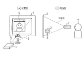
FIG. 1 is a diagram showing the arrangement of projectors and cameras that constitute the video conference system of the present embodiment. In the video conference system, a projector (projection device) 1 projects an image on a
カメラ(撮像装置)2でユーザ4を撮影する場合、図1(a)、(b)に示すように、カメラ2をユーザ4と対向するように設置、すなわち、カメラ2をプロジェクタ1と対向するように設置する必要がある。特に、自拠点のユーザ4と他拠点のユーザ5との視線を一致させるためには、図1(b)に示すように、ユーザ4の視線に近い高さにカメラ2を設置する必要がある。
When the user 4 is photographed by the camera (imaging device) 2, as shown in FIGS. 1A and 1B, the
この状態では、プロジェクタ1の投影光がカメラ2に映り込んでしまい、図2に示すように、カメラ2の撮影映像14における輝度が飽和して、映像14が見づらいものとなる。図2は、プロジェクタ1の投影光がカメラ2に映り込んだときの撮影映像14を模式的に表した図である。撮影映像14において、プロジェクタ1の投影口12の周囲は高輝度になり、映り込み光13が発生するため、撮影映像14が見づらいものとなる。
In this state, the projection light of the projector 1 is reflected on the
図3は、本実施形態のビデオ会議システムの構成例を示す図である。本実施形態のビデオ会議システムでは、プロジェクタ1と、カメラ2と、これらプロジェクタ1及びカメラ2に接続する映像処理装置8とを備える。相手側の対向装置21も同様の構成をとり、映像処理装置8はネットワーク7を介して対向装置21と接続し、映像や音声の送受信を行う。
FIG. 3 is a diagram illustrating a configuration example of the video conference system according to the present embodiment. The video conference system of this embodiment includes a projector 1, a
映像処理装置8は、音声出力部31と、音声入力部32と、表示制御部33と、操作部34と、映像出力部35と、映像入力部36と、通信部37と、全体制御部38とを備える。各部31〜37は内部バス等を介して全体制御部38と接続し、全体制御部38でそれぞれの制御を行う。
The
スピーカー41は音声出力部31と接続し、対向装置21が送信する音声を出力する。マイク42は音声入力部32と接続し、自拠点のユーザの音声を入力する。
The
ディスプレイ43は表示制御部33と接続し、映像処理装置8の操作画面等を表示する。ディスプレイ43としては、CRTや液晶ディスプレイ等の表示装置が挙げられるが、特定の表示装置に限定されない。マウス44は操作部34と接続し、ユーザの操作を入力する。もちろん、マウス44以外にも、キーボードやタッチパネル等の入力装置が接続する構成であってもよい。
The
映像出力部35はプロジェクタ1と接続し、プロジェクタ1に投影する映像を出力する。映像入力部36はカメラ2と接続し、カメラ2から撮影映像を受信する。プロジェクタ1と映像出力部35の接続形態、及び、カメラ2と映像入力部36の接続形態としては、USBやIEEE802.11等が挙げられるが、特定の接続形態に限定されるものではない。
The
通信部37はネットワーク7を介して対向装置21と接続し、映像や音声を送受信する。ネットワーク7は、インターネットに限らず、イントラネットやLAN等の様々なネットワークにより構成される。また、ネットワーク7を介して接続する対向装置21は1つに限定されない。
The
以上のようにした映像処理装置8は、例えばCPU、ROM、RAM等を具備する汎用のパーソナルコンピュータを用いて構成することが可能である。
The
次に、図4を参照して、本発明を適用した画像処理の基本原理を説明する。プロジェクタ1とスクリーン3の間にカメラ2を設置する場合に、プロジェクタ1により投影する映像に暗領域を重畳するように設定することによって、カメラ2の撮影映像への投影光の映り込みを減少させるものである。ここで、暗領域とは暗い色の領域のことであり、特定の色に限定されるものではない。
Next, the basic principle of image processing to which the present invention is applied will be described with reference to FIG. When the
図4(a)は、プロジェクタ1からスクリーン(投影位置)3を見たときの図である。スクリーン3の手前にカメラ2が設置されているため、プロジェクタ1により投影した映像51とカメラ2とが重なる。そこで、図4(b)に示すように、プロジェクタ1により投影した映像51上においてカメラ2に対応する部分、具体的にはプロジェクタ1からスクリーン3を見たときにカメラ2と重なる領域に暗領域を配置するように投影することで、投影映像51上に暗領域52を設定する。これにより、カメラ2への投影光の映り込みを減らすことできる。
FIG. 4A is a diagram when the screen (projection position) 3 is viewed from the projector 1. Since the
次に、図5及び図6を参照して、暗領域の設定方法について説明する。図5に示すように、ディスプレイ43に暗領域設定画面61を表示する。暗領域設定画面61において、映像62はプロジェクタ1がスクリーン3に投影する映像であり、例えば対向装置21から受信した映像が含まれる。また、映像63はカメラ2の撮像映像である。
Next, a dark region setting method will be described with reference to FIGS. As shown in FIG. 5, a dark
この暗領域設定画面61上において、カメラ2の撮影映像63を視認しながら、プロジェクタ1により投影する映像62上に暗領域64を設定することができる。このとき、カメラ2への映り込みの影響を低減するように、暗領域64の位置、大きさ等の属性をマウスポインタ65で操作し、調整する。
On the dark
図6に示すように、暗領域64の位置及び大きさの設定は、一般的なウィンドウシステムと同様、マウスポインタ65により暗領域64の周囲に設定された操作部分66をドラッグ等の操作をすることで行う。例えば操作部分66をドラッグしながら、左右にマウスポインタ65を移動させれば暗領域64の幅を変更することができ、上下にマウスポインタ65を移動させれば暗領域64の高さを変更することができる。また、斜めにマウスポインタ65を移動させれば暗領域64の高さ及び幅を同時に変更することができる。
As shown in FIG. 6, the position and size of the
なお、ここでは暗領域64の属性として、位置、大きさを説明したが、それ以外にも形状、色、柄、濃度等を任意に設定できるようにしても良い。例えば暗領域64の形状は矩形状に限られるものではなく、円形、楕円形や四角形、五角形等であってもよく、また、あらかじめ設定された複数の形状から選択可能としてもよい。
Although the position and size have been described as the attributes of the
次に、図7のフローチャートを参照して、暗領域64の設定手順について説明する。図7は、暗領域64を設定するときに全体制御部38が実行するソフトウェアの処理手順である。以下の処理手順が、本発明でいう暗領域設定手段の処理例となる。全体制御部38は、CPUに相当し、コンピュータ可読媒体であるROMからRAMに読み出されたプログラムを参照することにより図7の処理を実行する。
Next, the procedure for setting the
まず、ステップS101において、全体制御部38は、カメラ2から映像を取得し、ステップS102において、対向装置21から通信部37を介して映像(対向装置映像)を受信する。次に、ステップS103において、全体制御部38は、図5に示したように、ディスプレイ43に対向装置映像を含む映像62とカメラ2の撮影映像63とを同時に表示させる(暗領域設定画面)。また、ステップS104において、全体制御部38は、映像62をプロジェクタ1に投影させる。
First, in step S101, the
次に、ステップS105において、全体制御部38は、ディスプレイ43上の映像62に暗領域64を重畳して配置する。このとき、暗領域64が重畳された映像はプロジェクタ1より投影される。
Next, in step S <b> 105, the
そして、ステップS106において、全体制御部38は、図6で説明した手順により暗領域64の位置、大きさ、形状等の調整を行い、暗領域64を設定する。このとき、ディスプレイ43上のカメラ2の撮影映像63を見ながら、カメラ2への投影光の映り込みの影響が最小かどうかを目視で確認する。最小になったと判断した場合、終了する。
In step S106, the
以上の説明においては、映像処理装置8と対向装置21とをネットワーク経由で接続した構成としたが、本発明において対向装置21は必要ではない。例えば投影映像を閲覧する様子を録画するためにカメラ2を図1のように配置する場合がある。
In the above description, the
以上述べたように、プロジェクタ1の投影光が映り込む場所にカメラ2を設置した場合、プロジェクタ1により投影する映像51上に暗領域52を設定することにより、カメラ2への投影光の映り込みを減少させることができる。これにより、対向装置21での表示映像(カメラ2の撮影映像を含む)が従来の暗領域の重畳がないものに比べて、見やすいものとなる。
As described above, when the
ここまでは、プロジェクタ1により投影する映像51上に暗領域52を設定する構成を説明した。以下、映像51上のウィンドウや映像、操作を行うためのボタン等と暗領域52とが重畳することを避ける構成について説明する。ここでは、プロジェクタ1により投影する映像51は、複数の表示オブジェクト(本発明でいう表示部分)を階層的に配置してなるものとして説明する。
So far, the configuration in which the
図8に示すように、プロジェクタ1により投影する映像51上に暗領域52を設定したときに、表示オブジェクト(ウィンドウ81、ウィンドウ81内の映像(例えば対話者)82、操作を行うためのボタン83)が暗領域52に隠れてしまうことがある。この場合、ウィンドウ81内の対話者の顔を見ながら会話を行うときに、暗領域52が目障りなものとなってしまう。また、ボタン83を目視しにくくなり、操作性が低下してしまう。そこで、以下の述べるようにして、ウィンドウ81内の映像82やボタン83等の表示する必要がある部分と、暗領域52とが重畳することを避ける。
As shown in FIG. 8, when a
以下詳細に説明すると、まず、上述したように暗領域52の配置を行い、ウィンドウ81上で、人物の映像82や操作を行うためのボタン83等が配置された部分を重畳禁止領域84として設定する。このとき、スクリーン3に投影される映像を図9(a)に示す。次に、ウィンドウ81を移動させる、或いは、大きさを変更(縮小)させることにより、暗領域52と重畳禁止領域84との重畳を回避するようにウィンドウ81の配置を行う。このとき、スクリーン3に投影される映像を図9(b)に示す。
In detail, first, the
ここで、図10を参照して、重畳禁止領域84の設定方法について説明する。以下の処理手順が、本発明でいう重畳禁止領域設定手段の処理例となる。図10は、ディスプレイ43に表示する重畳禁止領域の設定画面1001を示す。図10では図示を省略するが、重畳禁止領域の設定画面1001には、例えばプロジェクタ1がスクリーン3に投影する映像51のうちウィンドウ81(図9を参照)が表示されている。
Here, with reference to FIG. 10, the setting method of the superimposition prohibition area |
まず、設定画面1001上において、マウスポインタ1002を操作することで、暗領域52との重畳を回避する必要がある部分に矩形領域1003を設定する。矩形領域1003の位置及び大きさの設定は、一般的なウィンドウシステムと同様、マウスポインタ1002により矩形領域1003の周囲に設定された操作部分1004をドラッグ等の操作をすることで行う。例えば操作部分1004をドラッグしながら、左右にマウスポインタ1002を移動させれば矩形領域1003の幅を変更することができ、上下にマウスポインタ1002を移動させれば矩形領域1003の高さを変更することができる。また、斜めにマウスポインタ1002移動させれば矩形領域1003の高さ及び幅を同時に変更することができる。
First, on the
矩形領域1003をそのまま重畳禁止領域84としてもよいが、重畳禁止領域84の形状を設定できるようにしてもよい。この場合、例えばあらかじめ設定された複数の形状から選択可能とすればよい。具体的には、図10に示すように楕円形の他にも、円形、五角形等があるが、本発明は特定の形状に限定されない。
The
このように重畳禁止領域84をウィンドウ81上に設定すると、ウィンドウ81が移動した場合、重畳禁止領域84もウィンドウ81の移動に対応して移動する。また、ウィンドウ81の大きさが変化した場合、重畳禁止領域84もウィンドウ81の大きさの変化に対応して変化する。
When the
また、重畳禁止領域84を設定する間、暗領域52にマウスポインタ1002が接近した場合、一時的に暗領域52の表示を中止する。これにより、暗領域52の近くでも、目視しながら重畳禁止領域84の設定を行うことができる。
Further, if the
図11は、映像処理装置8の映像出力部35に出力する映像の範囲(映像表示範囲)1101、ウィンドウ1102、重畳禁止領域1103及び暗領域1104の座標を示す図である。ウィンドウ1102、重畳禁止領域1103及び暗領域1104は、それぞれ図8、9に示すウィンドウ81、重畳禁止領域84、暗領域52に対応するものである。図12は、暗領域1104と重畳禁止領域1103との重畳を回避するようにウィンドウ1102の配置を行う処理を示すフローチャートである。
FIG. 11 is a diagram showing the coordinates of a video range (video display range) 1101 to be output to the
図12に示すように、開始後まずステップS1において、暗領域1104の配置を行う。次に、ステップS2において、ウィンドウ1102上の重畳禁止領域1103の設定を行う。そして、ステップS3において、暗領域1104と重畳禁止領域1103との重畳検出を行う。ステップS4において、ステップS3での重畳検出により暗領域1104と重畳禁止領域1103とが重畳すると判定された場合、ステップS5に進む。ステップS5おいて、ウィンドウ1102を操作し、再びステップS3において重畳検出を行う。一方で、ステップS4において、ステップS3での重畳検出により暗領域1104と重畳禁止領域1103とが重畳しないと判定された場合、本処理を終了する。
As shown in FIG. 12, after the start, first, in step S1, the
次に、図13を参照して、図12のステップS3の重畳検出処理について説明する。まずステップS11において、重畳禁止領域1103の位置、大きさ、形状を取得する。次に、ステップS12において、暗領域1104の位置、大きさ、形状を取得する。そして、ステップS13において、ステップS11及びS12で取得した位置、大きさ、形状を使用して、暗領域1104と重畳禁止領域1103との重畳を検出して、本処理を終了する。
Next, with reference to FIG. 13, the superposition detection process in step S3 of FIG. 12 will be described. First, in step S11, the position, size, and shape of the overlapping
次に、図14、15を参照して、図12のステップS5のウィンドウ操作処理について説明する。図14は、暗領域1104と重畳禁止領域1103との重畳を回避するために必要な距離Distと、ウィンドウ1102の移動可能距離Surとを示す。DistとSurにおいて、y軸マイナス方向をU、x軸プラス方向をR、y軸プラス方向をB、x軸マイナス方向をLとする。
Next, the window operation processing in step S5 in FIG. 12 will be described with reference to FIGS. FIG. 14 shows the distance Dist necessary for avoiding the overlap between the
図15は、ウィンドウ操作処理を示すフローチャートである。まずステップS21において、映像表示範囲1101の座標を取得する。また、ステップS22において、ウィンドウ1102の座標を取得する。また、ステップS23において、重畳禁止領域1103の座標を取得する。また、ステップS24において、暗領域1104の座標を取得する。
FIG. 15 is a flowchart showing the window operation process. First, in step S21, the coordinates of the
次に、ステップS25において、暗領域1104と重畳禁止領域1103との重畳を回避するために必要な距離Distと、ウィンドウ1102の移動可能距離Surとをそれぞれ求める。
Next, in step S25, a distance Dist necessary for avoiding the overlap between the
そして、ステップS31において、ウィンドウ1102の移動可能な方向があるか否かを判定する。移動可能な方向がない場合、ステップS32に進み、ウィンドウ1102の縮小を行う。ここでは、ウィンドウ1102を縦横の長さをα倍することで縮小する。
In step S31, it is determined whether there is a movable direction of the
一方で、移動可能な方向がある場合、ステップS33に進み、移動可能で移動距離が最小の方向、つまりDistが最も小さい方向を選択する。そして、ステップS34において、DistとSurとの比較を行うことで、ウィンドウ1102が移動可能か否かを判定する。ここで、ステップS34でウィンドウ1102が移動不能と判定した場合、ステップS35に進み、選択した方向を移動不可能とする。また、ステップS34でウィンドウ1102が移動可能と判定した場合、ステップS36に進み、ウィンドウ1102を選択した方向にDistだけ移動し、本処理を終了する。
On the other hand, if there is a movable direction, the process proceeds to step S33, and a direction that is movable and has the smallest movement distance, that is, a direction with the smallest Dist is selected. In step S34, it is determined whether the
以上述べたように、第1の実施形態では、ウィンドウ81上に重畳禁止領域84を設定すると、暗領域52と重畳禁止領域84との重畳を回避するように、ウィンドウ81の移動、縮小を行う。これにより、ウィンドウ81内の映像82や操作を行うためのボタン83が暗領域52の背後に隠れることを回避することができる。
As described above, in the first embodiment, when the
なお、本実施形態では、単一のウィンドウについて説明を行ったが、単一のウィンドウに対する操作に限定されるものではない。複数のウィンドウに対して、同様の手法により暗領域と重畳禁止領域との重畳を回避するように、ウィンドウを操作することが可能である。 In the present embodiment, a single window has been described, but the present invention is not limited to an operation on a single window. With respect to a plurality of windows, it is possible to operate the windows so as to avoid the overlapping of the dark area and the overlapping prohibition area by the same method.
(第2の実施形態)
図16は、本実施形態のビデオ会議システムの構成例を示す図である。本実施形態のビデオ会議システムでは、映像処理装置8´が投影装置制御部39を備えている。投影装置制御部39はプロジェクタ1と接続し、プロジェクタ1の投影位置、投影する大きさの制御を行う。全体制御部38は投影装置制御部39と内部バス等で接続し、投影制御部39の制御を行う。それ以外の各部の構成は、図3の映像処理装置8の構成と同様である。
(Second Embodiment)
FIG. 16 is a diagram illustrating a configuration example of the video conference system according to the present embodiment. In the video conference system of the present embodiment, the
本実施形態では、プロジェクタ1により投影した映像51上において暗領域52を設定する場合に、プロジェクタ1をメカ的にずらし、その後映像51上に暗領域52を重畳させる構成となっている。
In the present embodiment, when the
図17(a)は、暗領域52と重畳禁止領域84とが重畳している状態を示す。このとき、映像処理装置8´の投影装置制御部39がプロジェクタ1を制御して映像51の投影位置を変更し、投影可能範囲1105(図11を参照)内に投影する。これにより、図17(b)に示すように、暗領域52と重畳禁止領域84との重畳を回避する。また、投影装置制御部39が、投影する映像51の大きさを変更することで、暗領域52と重畳禁止領域84の重畳を回避するようにしてもよい。
FIG. 17A shows a state in which the
また、プロジェクタ1による映像51の投影位置を変更すると、スクリーン3に映る映像51が台形にゆがむことが考えられる。本実施形態では、投影した映像51がゆがんだ場合、プロジェクタ1によって補正を行う。
Further, when the projection position of the
図18は、暗領域1104と重畳禁止領域1103との重畳を回避するようにプロジェクタ1を制御する処理を示すフローチャートである。図18において、ステップS1〜S4は第1の実施形態のステップS1〜S4(図12を参照)と同様である。ステップS4において、ステップS3での重畳検出により暗領域1104と重畳禁止領域1103とが重畳すると判定された場合、ステップS6に進む。ステップS6おいて、投影装置制御部39によりプロジェクタ1を制御し、再びステップS3において重畳検出を行う。
FIG. 18 is a flowchart showing a process for controlling the projector 1 so as to avoid the overlapping of the
次に、図14、19を参照して、図18のステップS6のプロジェクタ制御処理について説明する。図14は、暗領域1104と重畳禁止領域1103との重畳を回避するために必要な距離Distと、映像表示範囲1101の移動可能距離Sur_aとを示す。DistとSur_aにおいて、y軸マイナス方向をU、x軸プラス方向をR、y軸プラス方向をB、x軸マイナス方向をLとする。
Next, the projector control process in step S6 in FIG. 18 will be described with reference to FIGS. FIG. 14 shows the distance Dist necessary for avoiding the overlap between the
図19は、プロジェクタ制御処理を示すフローチャートである。まずステップS111において、映像表示範囲1101の座標を取得する。また、ステップS112において、投影可能範囲1105の座標を取得する。また、ステップS113において、重畳禁止領域1103の座標を取得する。また、ステップS114において、暗領域1104の座標を取得する。
FIG. 19 is a flowchart showing the projector control process. First, in step S111, the coordinates of the
次に、ステップS115において、暗領域1104と重畳禁止領域1103との重畳を回避するために必要な距離Distと、映像表示範囲1101の移動可能距離Sur_aとをそれぞれ求める。
Next, in step S115, a distance Dist necessary for avoiding the overlap between the
そして、ステップS121において、映像表示範囲1101の移動可能な方向があるか否かを判定する。移動可能な方向がない場合、ステップS122に進み、映像表示範囲1101の縮小を行う。ここでは、映像表示範囲1101を縦横の長さをα倍することで縮小する。
In step S121, it is determined whether there is a movable direction of the
一方で、移動可能な方向がある場合、ステップS123に進み、移動可能で移動距離が最小の方向、つまりDistが最も小さい方向を選択する。そして、ステップS124において、DistとSur_aとの比較を行うことで、映像表示範囲1101が移動可能か否かを判定する。ここで、ステップS124で映像表示範囲1101が移動不能と判定した場合、ステップS125に進み、選択した方向を移動不可能とする。また、ステップS124で映像表示範囲1101が移動可能と判定した場合、ステップS126に進み、映像表示範囲1101を選択した方向にDistだけ移動し、本処理を終了する。
On the other hand, if there is a movable direction, the process proceeds to step S123, and a direction that is movable and has the smallest movement distance, that is, a direction with the smallest Dist is selected. In step S124, it is determined whether the
以上述べたように、第2の実施形態では、プロジェクタ1の投影位置、投影する大きさの制御することで、暗領域52と重畳禁止領域84との重畳を回避する。これにより、ウィンドウ81内の映像82や操作を行うためのボタン83が暗領域52の背後に隠れることを回避することができる。
As described above, in the second embodiment, the superimposition of the
(第3の実施形態)
第3の実施形態として、第1の実施形態と第2の実施形態とを組み合わせた例について説明する。映像処理装置の構成は第2の実施形態と同様である。この場合、第1の実施形態で説明したように、ウィンドウを移動、縮小することで暗領域と重畳禁止領域との重畳を回避できるにしておく。
(Third embodiment)
As the third embodiment, an example in which the first embodiment and the second embodiment are combined will be described. The configuration of the video processing apparatus is the same as that of the second embodiment. In this case, as described in the first embodiment, it is possible to avoid the overlap between the dark region and the overlap prohibition region by moving and reducing the window.
まず、第1の実施形態で説明したように、ウィンドウの移動操作により、暗領域と重畳禁止領域との重畳を回避することを試みる。ここで、重畳を回避することができない場合、第2の実施形態で説明したように、プロジェクタ1による投影映像の投影位置の変更操作により、暗領域と重畳禁止領域との重畳を回避することを試みる。ここでも、重畳を避けることができない場合、両方(すなわち、第1の実施形態で説明したウィンドウの移動操作及び第2の実施形態で説明したプロジェクタ制御)を同時に実行し、暗領域と重畳禁止領域との重畳を回避することを試みる。 First, as described in the first embodiment, an attempt is made to avoid superimposition of a dark region and a superimposition prohibition region by a window moving operation. Here, when the superimposition cannot be avoided, as described in the second embodiment, it is possible to avoid the superimposition of the dark region and the superimposition prohibited region by the operation of changing the projection position of the projected video by the projector 1. Try. Again, if superimposition cannot be avoided, both (that is, the window movement operation described in the first embodiment and the projector control described in the second embodiment) are executed simultaneously, and the dark region and the superposition prohibition region are performed. Attempt to avoid superimposition with.
(第4の実施形態)
第4の実施形態として、暗領域と重畳禁止領域との重畳を回避するために、ウィンドウ内のレイアウトを変更する手法について説明を行う。なお、映像処理装置の構成は第1の実施形態と同様である。
(Fourth embodiment)
As a fourth embodiment, a method for changing the layout in the window in order to avoid the overlap between the dark region and the overlap prohibition region will be described. The configuration of the video processing apparatus is the same as that of the first embodiment.
まず、基本原理について図20を使用して説明する。図20(a)に示すように、ここでは、単一のウィンドウ81上に重畳禁止領域84a及び重畳禁止領域84bが設定されている。これら重畳禁止領域84a、84bは、表示オブジェクトである映像82及びボタン83にそれぞれ設定されている。
First, the basic principle will be described with reference to FIG. As shown in FIG. 20A, here, a
このとき、図20(b)に示すように、表示オブジェクト82及び表示オブジェクト83を移動することで、暗領域52と重畳禁止領域84a、84bとが重畳することを回避する。表示オブジェクト82、83の移動は、表示オブジェクト82、83間に設定された位置関係を保持し、実行される。また、複数のウィンドウ上においても、上記と同様の操作により、暗領域と重畳禁止領域とが重畳することを避けることができる。
At this time, as shown in FIG. 20B, by moving the
表示オブジェクトの移動に関するフローチャートは、第1の実施形態の図15のフローチャートにおいて、ウィンドウと表示オブジェクトを置き換え、移動可能範囲の条件に表示オブジェクト間の位置関係を加えたものと同様である。 The flowchart related to the movement of the display object is the same as that in the flowchart of FIG. 15 of the first embodiment in which the window and the display object are replaced and the positional relationship between the display objects is added to the condition of the movable range.
以上述べたように、第4の実施形態では、重畳禁止領域84が設定された表示オブジェクトを移動することで、暗領域52と重畳することを避ける。これにより、ウィンドウ81内の映像82や操作を行うためのボタン83が暗領域52の背後に隠れることを回避することができる。
As described above, in the fourth embodiment, the display object in which the
(第5の実施形態)
第5の実施形態として、プロジェクタ1と対向するように設置されたカメラ2の撮影映像における輝度ヒストグラムを使用することで、暗領域64の設定を自動的に最適化する例について説明をする。なお、ビデオ会議システム全体の構成や各機器の構成は第1の実施形態と同様である。本実施形態でも、投影する画像の制御及び作成は全体制御部38上で動作するソフトウェアにおいて行う。
(Fifth embodiment)
As a fifth embodiment, an example in which the setting of the
まず、基本的な原理について説明を行う。本実施形態では、暗領域の属性を位置及び大きさとして各々を最適化する手法を説明する。暗領域の属性は位置及び大きさに限定されるものではなく、他の属性についても同様な手法による最適化が可能である。 First, the basic principle will be described. In the present embodiment, a method for optimizing each of the attributes of the dark region using the position and size will be described. The attributes of the dark region are not limited to the position and size, and other attributes can be optimized by the same method.
第5の実施形態では、プロジェクタ1により投影する映像62上における暗領域64の位置を決定する第一段階と、暗領域64の大きさを決定する第二段階の二段階の処理を実行する。これにより、プロジェクタ1により投影した映像51上のカメラ2に対応する部分(カメラ部分)に暗領域64を設定する。
In the fifth embodiment, a two-stage process is executed: a first stage for determining the position of the
第一段階では、全体制御部38において作成した白色の画像上に、所定の大きさの暗領域を配置してプロジェクタ1から投影を行う。すなわち、プロジェクタ1により投影する映像上に暗領域を仮に設定する。次に、仮設定した暗領域を配置した映像をカメラ2により撮影して取得し、輝度ヒストグラムを作成する。
In the first stage, a dark area of a predetermined size is arranged on the white image created by the
そして、暗領域を再配置し、輝度ヒストグラムを作成し、画像全体に対して輝度ヒストグラムを作成するまで繰り返す。ここで、暗領域の再配置は領域を上からまた、輝度ヒストグラムを作成する度に、図21に示すように、th階級から最も高輝度な階級までの度数の和Znを記憶する。thの値の設定に関しては、判別分析法等を用いてヒストグラムの谷を発見し設定を行う。判別分析法とは、分布を分離する閾値の決定する方法である。thの値に関しては、最初に決定した値を毎回使用する。 Then, the dark regions are rearranged, a luminance histogram is created, and the process is repeated until the luminance histogram is created for the entire image. Here, the rearrangement of the dark regions stores the sum Z n of the frequencies from the th class to the highest luminance class as shown in FIG. Regarding the setting of the value of th, a valley of a histogram is found and set using a discriminant analysis method or the like. The discriminant analysis method is a method for determining a threshold for separating distributions. As for the value of th, the value determined first is used each time.
度数の和Znは、以下の式(1)により求める。式(1)において、Imaxは輝度に関するヒストグラムの階級の最大を示し、Ithはth番目の階級を示す。Hiは輝度iのヒストグラムの度数である。 The sum of frequencies Z n is obtained by the following equation (1). In Expression (1), I max indicates the maximum of the histogram class relating to luminance, and I th indicates the th th class. H i is the frequency of the histogram of luminance i.

図22(a)は度数の和Znをグラフ化したものである。図22(a)中、横軸はヒストグラムの番号を示し暗領域の位置の変化に対応する。また、縦軸は度数の和の値Zを示す。 FIG. 22A is a graph of the frequency sum Z n . In FIG. 22A, the horizontal axis indicates the histogram number and corresponds to a change in the position of the dark region. The vertical axis indicates the value Z of the frequency sum.
図22(a)において、暗領域がカメラ部分に配置されたとき、配置されてない場合に比べて、度数の和の値Zが小さくなる。このため、値Zが最小となったときの暗領域の位置を暗領域の配置場所として決定すれば、カメラ部分に対応する位置に暗領域を配置することができる。 In FIG. 22A, when the dark area is arranged in the camera portion, the sum value Z of the frequencies becomes smaller than in the case where the dark area is not arranged. For this reason, if the position of the dark region when the value Z is minimized is determined as the dark region placement location, the dark region can be placed at a position corresponding to the camera portion.
第二段階では、暗領域の大きさの調整を行う。全体制御部38において作成した白色の画像上に、前記第一段階で決定した位置に暗領域を配置してプロジェクタ1から投影を行う。次に、全体制御部38においてカメラ2の撮影映像を取得し、輝度ヒストグラムを作成する。そして、暗領域を縮小し、暗領域の縦横どちらかの長さが0になるまで輝度ヒストグラムの作成を繰り返す。また、輝度ヒストグラムを作成する度に、th階級から最も高輝度な階級までの度数の和Znを式(1)を用いて求め記憶する。ここで、thの値の設定に関しては、前記第一段階と同様である。そして、式(2)を用いて暗領域1回縮小あたりにおける部分ヒストグラムの成分和Zmの変化量brmを求める。式(2)において、Zmはm回目の式(1)による度数の和を示す。
In the second stage, the size of the dark region is adjusted. On the white image created by the
図22(b)は成分和Zmの変化量brmをグラフ化したものである。図22(b)中、横軸はループの繰り返し回数を示し、縦軸は成分和Zmの変化量の値brを示す。 FIG. 22B is a graph of the change amount br m of the component sum Z m . In FIG. 22 (b), the horizontal axis represents the number of iterations of the loop, and the vertical axis represents the value br variation component sum Z m.
暗領域がカメラ2の大きさよりも小さくなった場合、カメラ2に投影光が映り込み、撮像画像中の高輝度な点が急増するため、度数の和の値Zが大きくなる。このため、図22(b)中Zの変化量brが最大のときを暗領域の大きさとすることで、カメラ部分に対応する大きさにすることができる。
When the dark area is smaller than the size of the
以上の手順を、図23に示す全体制御部38の動作処理フローチャートに示す。暗領域の設定開始後、全体制御部38は、ステップS201において暗領域の位置の最適化を行い(第一段階)、ステップS202において暗領域の大きさの最適化を行う(第二段階)。そして、ステップS203において全体制御部38は、暗領域の位置及び大きさをRAMに記憶し終了する。
The above procedure is shown in the operation processing flowchart of the
次に、図23(b)を参照して、ステップS201で定義した暗領域の位置の最適化手順について説明を行う。ここでは説明のため、縦横比は投影画像と同一で面積が1/s倍の黒い矩形を用いる。 Next, the procedure for optimizing the position of the dark area defined in step S201 will be described with reference to FIG. Here, for the sake of explanation, a black rectangle having the same aspect ratio as that of the projected image and an area of 1 / s times is used.
ステップS301において、全体制御部38は、白い画像上に暗領域を配置した画像をプロジェクタ1によって投影させる。ステップS302において、全体制御部38は、カメラ2の撮影映像を取得する。ステップS303において、全体制御部38は、輝度ヒストグラムを作成した後に、ステップS304において、特徴量として度数の和Znを計算し記憶する。ここで、暗領域の初期配置は白い画像上の左上端する。そして、全体制御部38は、暗領域を再配置するときは、暗領域を右に移動させ、右端まで達した場合は、左端に戻り暗領域を下に移動させる。ステップS305において、全体制御部38は、画像全体に対して暗領域を配置するまで、暗領域を再配置すると判断する。これにより、複数の映像のヒストグラムが生成されることになる。
In step S301, the
その後、ステップS306において、全体制御部38は、ステップS304で記憶した度数の和Znの比較を行い、和が最小となる暗領域の配置場所を決定し、ステップS307において、位置をメモリに記憶する。
After that, in step S306, the
次に、図23(b)を参照して、ステップS202で定義した暗領域の大きさの最適化手順について説明する。なお、ステップS201の処理とステップS202の処理を同じフローチャートを用いて説明するが、実際の処理は異なる。 Next, the procedure for optimizing the size of the dark region defined in step S202 will be described with reference to FIG. In addition, although the process of step S201 and the process of step S202 are demonstrated using the same flowchart, an actual process differs.
ステップS301において、全体制御部38は、白い画像上に暗領域を配置した画像をプロジェクタ1によって投影させる。ステップS302において、全体制御部38は、カメラ2の撮影映像を取得する。ステップS303において、全体制御部38は、輝度ヒストグラムを作成した後に、ステップS304において、度数の和Znを計算しメモリに記憶する。ここで、暗領域の初期位置及び大きさは、ステップS201で決定したものが使用され、暗領域縮小の割合は暗領域の上下左右から1ピクセルずつ縮小される。ステップS305において、全体制御部38は、暗領域の縦横どちらかの大きさが0になるまで、暗領域を再配置すると判断する。これにより、複数の映像のヒストグラムが生成されることになる。
In step S301, the
その後、ステップS306において、全体制御部38は、ステップS304で記憶した度数を用いて度数の変化量brを計算し、該変化量brが最大となる暗領域の大きさを求め、ステップS307において、大きさをメモリに記憶する。
Thereafter, in step S306, the
本実施形態では、輝度ヒストグラムを使用したが、使用するヒストグラムは輝度ヒストグラムに限定されない。例えばRGBカラーモデルの場合、RGB成分のそれぞれ、もしくは組み合わせ、もしくはすべてのヒストグラムの成分を使用することでも、暗領域の設定は可能である。 In this embodiment, the luminance histogram is used, but the histogram to be used is not limited to the luminance histogram. For example, in the case of the RGB color model, it is possible to set the dark region by using each of the RGB components, combinations, or all histogram components.
なお、本発明の目的は、上述した実施形態の機能を実現するソフトウェアのプログラムコードを記録した記憶媒体を、システム或いは装置に供給することによっても達成される。この場合、そのシステム或いは装置のコンピュータ(又はCPUやMPU)が記憶媒体に格納されたプログラムコードを読み出し実行する。 The object of the present invention can also be achieved by supplying a storage medium storing software program codes for realizing the functions of the above-described embodiments to a system or apparatus. In this case, the computer (or CPU or MPU) of the system or apparatus reads and executes the program code stored in the storage medium.
この場合、記憶媒体から読み出されたプログラムコード自体が上述した実施形態の機能を実現することになり、プログラムコード自体及びそのプログラムコードを記憶した記憶媒体は本発明を構成することになる。 In this case, the program code itself read from the storage medium realizes the functions of the above-described embodiments, and the program code itself and the storage medium storing the program code constitute the present invention.
プログラムコードを供給するための記憶媒体としては、例えば、フレキシブルディスク、ハードディスク、光ディスク、光磁気ディスク、CD−ROM、CD−R、磁気テープ、不揮発性のメモリカード、ROM等を用いることができる。 As a storage medium for supplying the program code, for example, a flexible disk, a hard disk, an optical disk, a magneto-optical disk, a CD-ROM, a CD-R, a magnetic tape, a nonvolatile memory card, a ROM, or the like can be used.
また、コンピュータが読み出したプログラムコードを実行することにより、上述した実施形態の機能が実現されるだけに限らない。例えば、そのプログラムコードの指示に基づき、コンピュータ上で稼動しているOS(基本システム或いはオペレーティングシステム)等が実際の処理の一部又は全部を行い、その処理によって上述した実施形態の機能が実現されてもよい。 Further, the functions of the above-described embodiments are not limited to being realized by executing the program code read by the computer. For example, an OS (basic system or operating system) running on the computer performs part or all of the actual processing based on an instruction of the program code, and the functions of the above-described embodiments are realized by the processing. May be.
さらに、記憶媒体から読み出されたプログラムコードが、コンピュータに挿入された機能拡張ボードやコンピュータに接続された機能拡張ユニットに備わるメモリに書き込まれる形態でもよい。この場合メモリに書き込まれた後、そのプログラムコードの指示に基づき、その機能拡張ボードや機能拡張ユニットに備わるCPU等が実際の処理の一部又は全部を行い、その処理によって上述した実施形態の機能が実現される。 Further, the program code read from the storage medium may be written in a memory provided in a function expansion board inserted into the computer or a function expansion unit connected to the computer. In this case, after being written in the memory, the CPU of the function expansion board or function expansion unit performs part or all of the actual processing based on the instruction of the program code, and the function of the above-described embodiment is performed by the processing. Is realized.
1 プロジェクタ
2 カメラ
3 スクリーン
7 ネットワーク
8 映像処理装置
31 音声出力部
32 音声入力部
33 表示制御部
34 操作部
35 映像出力部
36 映像入力部
37 通信部
38 全体制御部
39 投影装置制御部
41 スピーカー
42 マイク
43 ディスプレイ
44 マウス
DESCRIPTION OF SYMBOLS 1
Claims (11)
前記投影装置により投影される投影映像上の領域を前記撮像装置の撮影映像への投影光の映り込みを減少させるための暗領域に設定する暗領域設定手段と、
前記投影装置により投影される投影映像の表示部分上に重畳禁止領域を設定する重畳禁止領域設定手段と、
前記暗領域と前記重畳禁止領域との重畳が回避されるように、前記重畳禁止領域設定手段が前記重畳禁止領域を設定した表示部分を移動させ、或いは、大きさを変更させる重畳回避手段とを備えたことを特徴とする映像処理装置。 A video processing apparatus for connecting the image pickup device, in the installed Ru projection device so as to face the image pickup device,
A dark region setting means for setting a region on the projected image projected by the projection device as a dark region for reducing the reflection of projection light on the captured image of the imaging device ;
A superimposition prohibition region setting means for setting a superposition prohibition region on a display part of a projection image projected by the projection device;
Superimposition avoidance means for moving the display portion where the superposition prohibition area setting means sets the superposition prohibition area or changing the size so that the superimposition of the dark area and the superposition prohibition area is avoided. An image processing apparatus comprising the image processing apparatus.
前記投影装置により前記スクリーンに投影される投影映像上の領域のうち前記投影装置から前記スクリーンを見たときに前記撮像装置と重なる領域に暗領域を設定する暗領域設定手段と、A dark region setting means for setting a dark region in a region overlapping with the imaging device when the screen is viewed from the projection device among regions on a projected image projected onto the screen by the projection device;
前記投影装置により投影される投影映像上に重畳禁止領域を設定する重畳禁止領域設定手段と、A superimposition prohibition region setting means for setting a superimposition prohibition region on a projection image projected by the projection device;
前記投影映像の投影位置を変更する、或いは、前記投影映像の大きさを変更することにより、前記暗領域と前記重畳禁止領域との重畳を回避する重畳回避手段とを備えることを特徴とする映像処理装置。An image comprising: a superposition avoiding means for avoiding superposition of the dark region and the superposition prohibition region by changing a projection position of the projection video or changing a size of the projection video. Processing equipment.
前記投影装置により投影される投影映像上の領域を前記撮像装置の撮影映像への投影光の映り込みを減少させるための暗領域に設定する暗領域設定手段と、A dark region setting means for setting a region on the projected image projected by the projection device as a dark region for reducing the reflection of projection light on the captured image of the imaging device;
前記投影装置により投影される投影映像の表示部分を前記暗領域との重畳を回避するための重畳禁止領域に設定する重畳禁止領域設定手段と、A superimposition prohibition region setting means for setting a display portion of a projection image projected by the projection device as a superposition prohibition region for avoiding superimposition with the dark region;
前記重畳禁止領域設定手段により第1の重畳禁止領域と第2の重畳禁止領域が設定された場合、前記第1の重畳禁止領域に設定した第1の表示部分と前記第2の重畳禁止領域に設定した第2の表示部分とのレイアウトを変更することにより、前記第1及び第2の重畳禁止領域と前記暗領域との重畳を回避されるように前記第1及び第2の表示部分を移動させ、或いは、大きさを変更させる重畳回避手段とを備えることを特徴とする映像処理装置。When the first superposition prohibition area and the second superposition prohibition area are set by the superposition prohibition area setting means, the first display portion set in the first superposition prohibition area and the second superposition prohibition area The first and second display parts are moved so as to avoid the overlap between the first and second overlap prohibited areas and the dark area by changing the layout with the set second display part. Or a superimposition avoiding means for changing the size of the image processing apparatus.
前記投影装置により投影される投影映像上の領域を前記投影装置からの投影光の前記撮像装置への映り込みを減少させるための暗領域に設定する暗領域設定手段と、
前記投影装置により投影される投影映像の表示部分上に重畳禁止領域を設定する重畳禁止領域設定手段と、
前記暗領域と前記重畳禁止領域との重畳が回避されるように前記重畳禁止領域設定手段が前記重畳禁止領域を設定した表示部分を移動させ、或いは、大きさを変更させる重畳回避手段とを備えたことを特徴とする映像処理システム。 A projection device, wherein an imaging device that will be installed so as to face the projection device, a video processing system comprising a video processing device connected to the projector,
A dark region setting means for setting a region on a projection image projected by the projection device as a dark region for reducing the reflection of projection light from the projection device on the imaging device ;
A superimposition prohibition region setting means for setting a superposition prohibition region on a display part of a projection image projected by the projection device;
Moves the display portion where the said superimposed forbidden area setting means so superposition between the dark region and the overlapped forbidden area can be avoided to set the superposition prohibition region, or a superposition avoiding means for changing the size A video processing system characterized by that.
前記投影装置により前記スクリーンに投影される投影映像上の領域のうち前記投影装置から前記スクリーンを見たときに前記撮像装置と重なる領域に暗領域を設定する暗領域設定手段と、A dark region setting means for setting a dark region in a region overlapping with the imaging device when the screen is viewed from the projection device among regions on a projected image projected onto the screen by the projection device;
前記投影装置により投影される投影映像上に重畳禁止領域を設定する重畳禁止領域設定手段と、A superimposition prohibition region setting means for setting a superimposition prohibition region on a projection image projected by the projection device;
前記投影映像の投影位置を変更する、或いは、前記投影映像の大きさを変更することにより、前記暗領域と前記重畳禁止領域との重畳を回避する重畳回避手段とを備えることを特徴とする映像処理システム。An image comprising: a superposition avoiding means for avoiding superposition of the dark region and the superposition prohibition region by changing a projection position of the projection video or changing a size of the projection video. Processing system.
前記投影装置により投影される投影映像上の領域を前記撮像装置の撮影映像への投影光の映り込みを減少させるための暗領域に設定する暗領域設定手段と、A dark region setting means for setting a region on the projected image projected by the projection device as a dark region for reducing the reflection of projection light on the captured image of the imaging device;
前記投影装置により投影される投影映像の表示部分を前記暗領域との重畳を回避するための重畳禁止領域に設定する重畳禁止領域設定手段と、A superimposition prohibition region setting means for setting a display portion of a projection image projected by the projection device as a superposition prohibition region for avoiding superimposition with the dark region;
前記重畳禁止領域設定手段により第1の重畳禁止領域と第2の重畳禁止領域が設定された場合、前記第1の重畳禁止領域に設定した第1の表示部分と前記第2の重畳禁止領域に設定した第2の表示部分とのレイアウトを変更することにより、前記第1及び第2の重畳禁止領域と前記暗領域との重畳を回避されるようにされるように前記第1及び第2の表示部分を移動させ、或いは、大きさを変更させる重畳回避手段とを備えることを特徴とする映像処理システム。When the first superposition prohibition area and the second superposition prohibition area are set by the superposition prohibition area setting means, the first display portion set in the first superposition prohibition area and the second superposition prohibition area By changing the layout with the set second display portion, the first and second superimposing areas can be avoided from overlapping with the first and second superimposing prohibition areas. An image processing system comprising: a superimposition avoiding unit that moves a display part or changes a size thereof.
前記投影装置により投影される投影映像上の領域を前記撮像装置の撮影映像への投影光の映り込みを減少させるための暗領域に設定する暗領域設定手順と、
前記投影装置により投影される投影映像の表示部分上に重畳禁止領域を設定する重畳禁止領域設定手順と、
前記暗領域と前記重畳禁止領域との重畳が回避されるように、前記重畳禁止領域設定手順において前記重畳禁止領域を設定した表示部分を移動させ、或いは、大きさを変更させる重畳回避手順とを実行させるためのプログラム。 An imaging device, a computer connected to the installed Ru projection device so as to face the image pickup device,
A dark region setting procedure for setting a region on a projection image projected by the projection device as a dark region for reducing the reflection of projection light on a captured image of the imaging device ;
A superposition prohibition region setting procedure for setting a superposition prohibition region on a display part of a projection image projected by the projection device;
A superposition avoidance procedure that moves or changes the size of the display portion in which the superposition prohibition region is set in the superposition prohibition region setting procedure so that superimposition of the dark region and the superposition prohibition region is avoided. program to be run.
前記投影装置により前記スクリーンに投影される投影映像上の領域のうち前記投影装置から前記スクリーンを見たときに前記撮像装置と重なる領域に暗領域を設定する暗領域設定手順と、A dark region setting procedure for setting a dark region in a region overlapping with the imaging device when the screen is viewed from the projection device among regions on a projected image projected onto the screen by the projection device;
前記投影装置により投影される投影映像上に重畳禁止領域を設定する重畳禁止領域設定手順と、A superposition prohibition region setting procedure for setting a superposition prohibition region on a projection image projected by the projection device;
前記投影映像の投影位置を変更する、或いは、前記投影映像の大きさを変更することにより、前記暗領域と前記重畳禁止領域との重畳を回避する重畳回避手順とを実行させるためのプログラム。A program for executing a superposition avoidance procedure for avoiding superposition of the dark region and the superposition prohibition region by changing the projection position of the projection video or changing the size of the projection video.
前記投影装置により投影される投影映像上の領域を前記撮像装置の撮影映像への投影光の映り込みを減少させるための暗領域に設定する暗領域設定手順と、A dark region setting procedure for setting a region on a projection image projected by the projection device as a dark region for reducing the reflection of projection light on a captured image of the imaging device;
前記投影装置により投影される投影映像の表示部分を前記暗領域との重畳を回避するための重畳禁止領域に設定する重畳禁止領域設定手順と、A superposition prohibition region setting procedure for setting a display portion of a projection image projected by the projection device as a superposition prohibition region for avoiding superimposition with the dark region;
前記重畳禁止領域設定手順において第1の重畳禁止領域と第2の重畳禁止領域が設定された場合、前記第1の重畳禁止領域に設定した第1の表示部分と前記第2の重畳禁止領域に設定した第2の表示部分とのレイアウトを変更することにより、前記第1及び第2の重畳禁止領域と前記暗領域との重畳を回避されるようにされるように前記第1及び第2の表示部分を移動させ、或いは、大きさを変更させる重畳回避手順とを実行させるためのプログラム。When the first superposition prohibition area and the second superposition prohibition area are set in the superposition prohibition area setting procedure, the first display portion set in the first superposition prohibition area and the second superposition prohibition area By changing the layout with the set second display portion, the first and second superimposing areas can be avoided from overlapping with the first and second superimposing prohibition areas. A program for executing a superposition avoidance procedure for moving the display part or changing the size.
Priority Applications (1)
| Application Number | Priority Date | Filing Date | Title |
|---|---|---|---|
| JP2008286923A JP5171560B2 (en) | 2008-11-07 | 2008-11-07 | Video processing apparatus, system, and program |
Applications Claiming Priority (1)
| Application Number | Priority Date | Filing Date | Title |
|---|---|---|---|
| JP2008286923A JP5171560B2 (en) | 2008-11-07 | 2008-11-07 | Video processing apparatus, system, and program |
Publications (3)
| Publication Number | Publication Date |
|---|---|
| JP2010114769A JP2010114769A (en) | 2010-05-20 |
| JP2010114769A5 JP2010114769A5 (en) | 2011-12-22 |
| JP5171560B2 true JP5171560B2 (en) | 2013-03-27 |
Family
ID=42302961
Family Applications (1)
| Application Number | Title | Priority Date | Filing Date |
|---|---|---|---|
| JP2008286923A Expired - Fee Related JP5171560B2 (en) | 2008-11-07 | 2008-11-07 | Video processing apparatus, system, and program |
Country Status (1)
| Country | Link |
|---|---|
| JP (1) | JP5171560B2 (en) |
Families Citing this family (6)
| Publication number | Priority date | Publication date | Assignee | Title |
|---|---|---|---|---|
| JP6102215B2 (en) * | 2011-12-21 | 2017-03-29 | 株式会社リコー | Image processing apparatus, image processing method, and program |
| JP6381235B2 (en) * | 2014-03-07 | 2018-08-29 | キヤノン株式会社 | Projection apparatus, image projection method, and program |
| JP2015192247A (en) | 2014-03-27 | 2015-11-02 | ブラザー工業株式会社 | Program and terminal device |
| JP6354567B2 (en) * | 2014-12-19 | 2018-07-11 | ブラザー工業株式会社 | Control device, program, and projection system |
| JP6307706B2 (en) * | 2014-12-25 | 2018-04-11 | パナソニックIpマネジメント株式会社 | Projection device |
| JP6550485B2 (en) * | 2018-02-07 | 2019-07-24 | シャープ株式会社 | Display device, control program and control method |
Family Cites Families (5)
| Publication number | Priority date | Publication date | Assignee | Title |
|---|---|---|---|---|
| JPH1011263A (en) * | 1996-06-20 | 1998-01-16 | Sharp Corp | Multiwindow system |
| JP2000020207A (en) * | 1998-07-01 | 2000-01-21 | Fujitsu Ltd | Window controller and recording medium |
| JP3674474B2 (en) * | 2000-08-04 | 2005-07-20 | ヤマハ株式会社 | Video system |
| NO318883B1 (en) * | 2003-04-07 | 2005-05-18 | Tandberg Telecom As | Arrangement and procedure for improved communication between participants in a video conference |
| JP2007251273A (en) * | 2006-03-13 | 2007-09-27 | Oki Electric Ind Co Ltd | Image processing device, image processing method, and image transmission system |
-
2008
- 2008-11-07 JP JP2008286923A patent/JP5171560B2/en not_active Expired - Fee Related
Also Published As
| Publication number | Publication date |
|---|---|
| JP2010114769A (en) | 2010-05-20 |
Similar Documents
| Publication | Publication Date | Title |
|---|---|---|
| US10547778B2 (en) | Image display device for displaying an image in an image display area, and storage medium storing image display program for displaying an image in an image display area | |
| US10681320B2 (en) | Projection apparatus, method for controlling projection apparatus, and non-transitory storage medium | |
| JP5171560B2 (en) | Video processing apparatus, system, and program | |
| US8727539B2 (en) | Projector and method of controlling projector | |
| JP5197777B2 (en) | Interface device, method, and program | |
| US9791933B2 (en) | Projection type image display apparatus, image projecting method, and computer program | |
| JP5521855B2 (en) | Projection image area detection device | |
| US10134118B2 (en) | Information processing apparatus and method of obtaining information about a projection surface on which a target is projected | |
| US10431131B2 (en) | Projector and control method for projector | |
| US9906762B2 (en) | Communication apparatus, method of controlling communication apparatus, non-transitory computer-readable storage medium | |
| US20130106908A1 (en) | Display device, control method of display device, and non-transitory computer-readable medium | |
| CN107817924B (en) | Display device and control method of display device | |
| JP2009031334A (en) | Projector and projection method for projector | |
| JP6064321B2 (en) | Display device and display control method | |
| JP5245805B2 (en) | Projector, control method therefor, and control program therefor | |
| JP2019204034A (en) | Projection control device, control method thereof, projection system, program and storage medium | |
| JP2010114768A (en) | Video processing unit, system, and program | |
| KR101709529B1 (en) | Apparatus and method for controlling image screen using portable terminal | |
| CN113760139A (en) | Information processing method and device, equipment and storage medium | |
| JP2018142856A (en) | Projector, and method for controlling projector | |
| JP2017102461A (en) | Display device and display control method | |
| US20190327457A1 (en) | Projection control apparatus and projection control method | |
| JP2020127162A (en) | Projection type video display system | |
| JP2014163979A (en) | Projector device, control method thereof, and control program | |
| US11812150B2 (en) | Imaging device performing enlargement processing based on specified area of object image, storage medium, and method of displaying object image |
Legal Events
| Date | Code | Title | Description |
|---|---|---|---|
| A521 | Request for written amendment filed |
Free format text: JAPANESE INTERMEDIATE CODE: A523 Effective date: 20111107 |
|
| A621 | Written request for application examination |
Free format text: JAPANESE INTERMEDIATE CODE: A621 Effective date: 20111107 |
|
| A977 | Report on retrieval |
Free format text: JAPANESE INTERMEDIATE CODE: A971007 Effective date: 20121116 |
|
| TRDD | Decision of grant or rejection written | ||
| A01 | Written decision to grant a patent or to grant a registration (utility model) |
Free format text: JAPANESE INTERMEDIATE CODE: A01 Effective date: 20121127 |
|
| A61 | First payment of annual fees (during grant procedure) |
Free format text: JAPANESE INTERMEDIATE CODE: A61 Effective date: 20121225 |
|
| R151 | Written notification of patent or utility model registration |
Ref document number: 5171560 Country of ref document: JP Free format text: JAPANESE INTERMEDIATE CODE: R151 |
|
| FPAY | Renewal fee payment (event date is renewal date of database) |
Free format text: PAYMENT UNTIL: 20160111 Year of fee payment: 3 |
|
| LAPS | Cancellation because of no payment of annual fees |